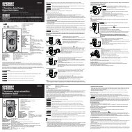
Manual - Sperry Instruments
Manual - Sperry Instruments
Manual - Sperry Instruments

Create successful ePaper yourself
Turn your PDF publications into a flip-book with our unique Google optimized e-Paper software.
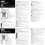
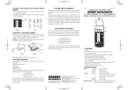
4.5) HOW TO USE POINTER LOCK & RANGE FINDER<br />
SYMBOLS<br />
(1) Slide the pointer lock button to the left. This allows easy readings in dimly lit<br />
or crowded cable areas (Fig.8).<br />
(2) For quick and easy identification the dial drum is marked with the symbols as<br />
illustrated below (Fig.9).<br />
5) BATTERY & FUSE REPLACEMENT<br />
(1) Remove the screw on the back of the case for battery and fuse replacement<br />
(Fig.10). Replace only with AWS fuse part F-1 or approved equal. 1/2A, 250V,<br />
1/4"×1-1/4" Fast acting High Current interrupting style fuse.<br />
CAUTION : For continued protection against fire, replace only with fuse of the<br />
specified voltage current and rupture speed ratings.<br />
Back<br />
Case<br />
Screw<br />
Fig.8<br />
Fig.10<br />
Pointer<br />
Lock<br />
Ampere<br />
range<br />
to the<br />
right.<br />
Lower<br />
range<br />
to the<br />
left.<br />
Fig.9<br />
Fig.11<br />
(2) The battery and fuse are installed inside the case (Fig.11).<br />
Higher<br />
range<br />
to the<br />
right.<br />
Lower<br />
range<br />
to the<br />
left.<br />
Spare<br />
Fuse<br />
Battery<br />
Fuse<br />
6) RETURN FOR REPAIR<br />
Before returning your instrument for repair make sure the failure to operate is<br />
not caused by:<br />
1) Weak or de-energized battery<br />
2) Fuse blown<br />
3) Broken test leads<br />
4) Pointer lock closed<br />
If all of these conditions are checked to be fine and your instrument still does not<br />
operate properly then send it bake freight prepaid to:<br />
<strong>Sperry</strong> <strong>Instruments</strong><br />
2150 Joshua's Path, Suite 302<br />
Hauppauge, NY 11788<br />
Include all accessories and a note explaining what is wrong with the instrument.<br />
Should you require an estimate please indicate ESTIMATE ONLY on your note. Be<br />
certain to include your return address and day time phone number should we<br />
need to contact you.<br />
LIFETIME LIMITED WARRANTY<br />
The attention to detail of this fine snap-around instrument is further enhanced by<br />
the application of <strong>Sperry</strong>'s unmatched service and concern for detail and<br />
reliability.<br />
These <strong>Sperry</strong> snap-arounds are internationally accepted by craftsman and<br />
servicemen for their unmatched performance. All <strong>Sperry</strong>'s snap-around<br />
instruments are unconditionally warranted against defects in material and<br />
workmanship under normal conditions of use and service; our obligations under<br />
this warranty being limited to repairing or replacing, free of charge, at <strong>Sperry</strong>'s<br />
sole option, any such <strong>Sperry</strong> snap-around instrument that malfunctions under<br />
normal operating conditions at rated use. 1<br />
REPLACEMENT PROCEDURE<br />
Securely wrap the instrument and its accessories in a box or mailing bag and<br />
ship prepaid to the address below. Be sure to include your name and address, as<br />
well as the name of the distributor, with a copy of your invoice from whom the<br />
unit was purchased, clearly identifying the model number and date of purchase.<br />
<strong>Sperry</strong> <strong>Instruments</strong><br />
ATT : Customer Service Dept.<br />
2150 Joshua's Path, Suite 302,<br />
Hauppauge, NY 11788<br />
1<br />
The warranty is not applicable if the instrument has been misused, abused,<br />
subjected to loads in excess of specifications, has had unauthorized repair or has<br />
been improperly assembled or used.<br />
05/06 From #174-1<br />
<br />
<br />
<br />
1) FEATURES<br />
・UL Listed<br />
・New range finder symbols give quick and easy locations of all ranges.<br />
・Three functions, nine ranges.<br />
・Large optically clear window gives quick, easy distortion - free readings.<br />
・One AA type battery AWS Part AWS B-1 included.<br />
・Two fuses(one spare), both included. AWS Part #F-1.<br />
・Volt, Ohm and Common terminals are on the front panel.<br />
・Ohm scale on dial drum.<br />
・Industry standard safety shielded banana plugs and recessed input terminals included.<br />
・Pointer lock device to freeze readings.<br />
・1.5 Ampere range for low current equipment.<br />
2) SPECIFICATIONS<br />
Range : AC Current 6/20/60/200/600 Aac<br />
AC Voltage<br />
Resistance<br />
150/300/600 Vac<br />
0-2K/25 ohm mid scale<br />
Accuracy : AC Current ±3% of full scale at 50-60Hz<br />
Withstand Voltage :<br />
AC Voltage<br />
Resistance<br />
±6% of full scale except 6A range at 400Hz<br />
10% of full scale on 6A range at 400Hz<br />
±3% of full scale<br />
±3% of arc length<br />
2,500 V AC for one minute between electrical circuit and<br />
housing case or metal section of transformer jaws.
Insulation Protection : 10MΩ min. at 1000 V between electrical circuit and<br />
housing or metal section of transformer jaws.<br />
Overload Protection : AWS Part #F-1,0.5A, 250V, 1/4"×1-1/4" fuse and<br />
diode<br />
Frequency Response : 50-400Hz<br />
Conductor Size : Approx. 1.2"(30mm)<br />
Dimensions :<br />
8.7"(L)×3.3"(W)×1.6"(D)<br />
220mm (L) ×83mm (W) ×40mm (D)<br />
Weight :<br />
Approx. 13.8 oz. (390g)battery included<br />
Power Source : One 1.5V AA size battery, AWS Part #B-1<br />
Fuse :<br />
1/4"×1-1/4", .5A, 250V FF AWS Part #F-1<br />
Temperature :<br />
5 to 40 Max RH 80% to 31, decreasing<br />
linearly to 50% RH at 40<br />
Cleaning :<br />
Wipe with a clean dry cloth.<br />
Accessories : (included) Test Leads Model TL-52 one alligator, one with prod.<br />
Banana Plugs are shrouded, Battery B-1, AA type 1.5V.<br />
Two 0.5/250V Fuses F-1 (spare fuse included),<br />
durable Case C-53.<br />
(optional) Energizer Model E-1, AG-940, TL-5, TL-5-A1, TL6,<br />
TL6-A1, TL-39, TL-42, TL-44, TL-48, TL-49 and<br />
C-53A Carrying Case.<br />
Instrument complies with insulation category (Overvoltage Category ll). Pollution<br />
Degree 2 in accordance with IEC-664. Indoor use.<br />
If the equipment is used in a manner not specified, the protection provided by<br />
the equipment may be impaired.<br />
3) SAFETY PRECAUTIONS<br />
The following safety precautions must be observed to insure maximum personal<br />
safety during the operation, service and repair of this meter :<br />
1. Read these operating instructions thoroughly and completely before<br />
operating your meter. Pay particular attention to WARNINGS which will<br />
inform you of potentially dangerous procedures. The instruction in these<br />
warnings must be followed.<br />
2. Always inspect your meter, test leads and accessories for any sign of<br />
damage or abnormality before every use. If any abnormal conditions exist<br />
(eg. broken test leads, cracked cases, etc.), do not attempt to take any<br />
measurements. Refer to Return for Repair section.<br />
3. Do not expose the instrument to direct sunlight, extreme temperature or moisture.<br />
4. Never ground yourself when taking electrical measurements. Do not touch<br />
exposed metal pipes, outlets, fixtures, etc., which might be at ground<br />
potential. Keep your body isolated from ground by using dry clothing, rubber<br />
shoes, rubber mats, or any approved insulating material.<br />
5. To avoid electric shock use CAUTION when working with Voltages above 40<br />
Vdc or 20 Vac. Such voltages pose a shock hazard.<br />
6. Never exceed the maximum allowable input value of any function when taking<br />
a measurement. Refer to the specifications on page 1 for maximum inputs.<br />
7. Never touch exposed wiring, connections or any live circuit when attempting<br />
to take measurements.<br />
8. Do not attempt to operate this instrument in an explosive atmosphere (i. e.<br />
in the presence of flammable gases or fumes, vapor or dust).<br />
9. When testing for the presence of voltage, make sure the voltage function is<br />
operating properly by reading a known voltage in that function before<br />
assuming that a zero reading indicates a no-voltage condition. Always test<br />
your meter before and after taking measurements on a known live circuit.<br />
10. Calibration and repair of any instrument should only be performed by<br />
qualified and trained service technicians.<br />
11. Do not attempt calibration or service unless trained and another person,<br />
capable of rendering first-aid and resuscitation, is present.<br />
12. Do not install substitute parts or perform any unauthorized modification of<br />
the instrument. Return the instrument to <strong>Sperry</strong> <strong>Instruments</strong>, Inc. for service<br />
and repair to insure that safety features are maintained.<br />
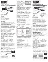
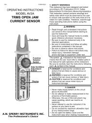
4) OPERATION<br />
BEFORE PROCEEDING WITH ANY MEASUREMENT, READ THE SAFETY<br />
PRECAUTIONS SECTION 3.<br />
4.1) PREPARATION<br />
(1) To ensure greatest accuracy, the pointer should be set exactly to the zero<br />
position by rotating the zero adjust screw (Fig 1).<br />
(2) Make certain that the pointer lock button is in the open position (Fig. 1).<br />
4.2) AC CURRENT MEASUREMENTS<br />
WARNING !<br />
This instrument is designed to take current readings on circuits with a<br />
maximum voltage above ground not exceeding 600 Vac. Using it on<br />
circuits above 600 Vac poses a shock hazard to the user.<br />
(1) Set the range switch to the highest 150 Aac range position.<br />
(2) Press the trigger to open the transformer jaws and clamp onto one conductor<br />
only (Fig. 2). Read the current directly on the scale. It is recommended that the<br />
conductor be placed at the center of the closed jaws for maximum accuracy.<br />
(3) When the reading is less than one third of the scale set the range switch to<br />
the next lower range position. For maximum accuracy, select the lowest<br />
range possible without overranging the meter.<br />
4.3) AC VOLTAGE MEASUREMENTS<br />
WARNING !<br />
This instrument is designed to take voltage readings up to a maximum<br />
of 600 Vac. The “COM”terminal voltage should not exceed 500 V<br />
measured to ground potential. Do not exceed these maximums.<br />
(1) Insert the red test lead into the “VOLT”terminal of the instrument and the<br />
black test lead into the “COM” terminal (Fig.3).<br />
Fig.3<br />
Fig.1<br />
Wrong<br />
Com<br />
Fig.2<br />
Volt<br />
Pointer Lock<br />
Zero Adjust<br />
Correct<br />
(2) Set the range switch to the highest Vac range position.<br />
(3) Connect the test leads to the circuit under test (Fig.4) and read the voltage<br />
directly on the scale.<br />
(4) When the reading is less than one half of the scale set the range switch to the<br />
next lower range position. For maximum accuracy, select the lowest range<br />
possible without overranging the meter.<br />
4.4) RESISTANCE MEASUREMENTS<br />
WARNING !<br />
Attempting resistance measurements on live circuits can cause electrical<br />
shock, damage to the instrument and damage to the equipment under<br />
test. Resistance measurements must be made on de-energized (DEAD)<br />
circuits only for maximum personal safety. The fuse protection installed<br />
in this instrument will reduce the possibility of damage to the instrument<br />
but not necessarily avoid all damage or shock hazard.<br />
Never jump out the protective fuse. Replace the fuse with AWS Part #F-1 or approved<br />
equal. Only use fuses that are quick acting and have high current interrupting capacities.<br />
(1) Teat the circuit to make sure it is de-energized. Refer to section 4.3 on how<br />
to test for voltage.<br />
(2) Set the range switch to the ohm range position. Insert the red test lead into<br />
the “OHM” terminal and black test lead into the “COM” terminal Fig.5.<br />
Ohm<br />
Fig.4<br />
Fig.5<br />
(3) With the test leads open set the pointer over the “∞”infinitymark at the left<br />
end of the ohm scale, using the zero adjust screw.<br />
(4) With the test leads shorted set the pointer over the “0”mark at the right end<br />
of the ohm scale, using the ohm zero adjust knob (Fig.6).<br />
Note : When this adjustment does not bring the pointer over the “0”mark replace the<br />
battery.<br />
Fig.6<br />
Ohm Zero<br />
Adj. Knob<br />
Com<br />
Fig.7<br />
(5) Connect the test leads to the circuit under test (Fig.7) and read the resistance<br />
directly on the scale.