model 25-om-dup-10/10-c & 25-oa-dup-10/10-c hydraulic ... - SPX
model 25-om-dup-10/10-c & 25-oa-dup-10/10-c hydraulic ... - SPX
model 25-om-dup-10/10-c & 25-oa-dup-10/10-c hydraulic ... - SPX

Create successful ePaper yourself
Turn your PDF publications into a flip-book with our unique Google optimized e-Paper software.
<strong>SPX</strong> Corporation<br />
5885 11th Street<br />
Rockford, IL 61<strong>10</strong>9-3699 USA<br />
Internet Address:<br />
http://www.powerteam.c<strong>om</strong><br />
Tech. Services: (800) 477-8326<br />
Fax: (800) 765-8326<br />
Order Entry: (800) 541-1418<br />
Fax: (800) 288-7031<br />
®<br />
Form No. <strong>10</strong>00033<br />
Operating Instructions and<br />
Parts List for:<br />
<strong>25</strong>-OM-DUP-<strong>10</strong>-C<br />
<strong>25</strong>-OA-DUP-<strong>10</strong>-C<br />
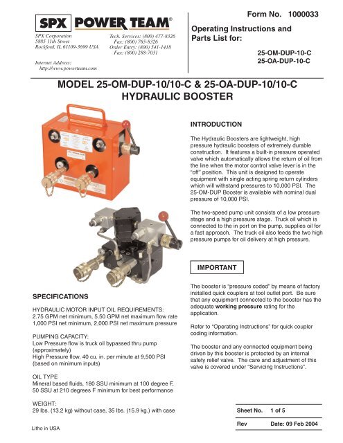
MODEL <strong>25</strong>-OM-DUP-<strong>10</strong>/<strong>10</strong>-C & <strong>25</strong>-OA-DUP-<strong>10</strong>/<strong>10</strong>-C<br />
HYDRAULIC BOOSTER<br />
INTRODUCTION<br />
The Hydraulic Boosters are lightweight, high<br />
pressure <strong>hydraulic</strong> boosters of extremely durable<br />
construction. It features a built-in pressure operated<br />
valve which aut<strong>om</strong>atically allows the return of oil fr<strong>om</strong><br />
the line when the motor control valve lever is in the<br />
“off” position. This unit is designed to operate<br />
equipment with single acting spring return cylinders<br />
which will withstand pressures to <strong>10</strong>,000 PSI. The<br />
<strong>25</strong>-OM-DUP Booster is available with n<strong>om</strong>inal dual<br />
pressure of <strong>10</strong>,000 PSI.<br />
The two-speed pump unit consists of a low pressure<br />
stage and a high pressure stage. Truck oil which is<br />
connected to the in port on the pump, supplies oil for<br />
a fast appr<strong>oa</strong>ch. The truck oil also feeds the two high<br />
pressure pumps for oil delivery at high pressure.<br />
IMPORTANT<br />
SPECIFICATIONS<br />
HYDRAULIC MOTOR INPUT OIL REQUIREMENTS:<br />
2.75 GPM net minimum, 5.50 GPM net maximum flow rate<br />
1,000 PSI net minimum, 2,000 PSI net maximum pressure<br />
PUMPING CAPACITY:<br />
Low Pressure flow is truck oil bypassed thru pump<br />
(approximately)<br />
High Pressure flow, 40 cu. in. per minute at 9,500 PSI<br />
(based on minimum inputs)<br />
OIL TYPE<br />
Mineral based fluids, 180 SSU minimum at <strong>10</strong>0 degree F,<br />
50 SSU at 2<strong>10</strong> degrees F minimum for best performance<br />
WEIGHT:<br />
29 lbs. (13.2 kg) without case, 35 lbs. (15.9 kg.) with case<br />
Litho in USA<br />
The booster is “pressure coded” by means of factory<br />
installed quick couplers at tool outlet port. Be sure<br />
that any equipment connected to the booster has the<br />
adequate working pressure rating for the<br />
application.<br />
Refer to “Operating Instructions” for quick coupler<br />
coding information.<br />
The booster and any connected equipment being<br />
driven by this booster is protected by an internal<br />
safety relief valve. The care and adjustment of this<br />
valve is covered under “Servicing Instructions”.<br />
Sheet No. 1 of 5<br />
Rev Date: 09 Feb 2004
Operating Instructions and Parts List, Form No. <strong>10</strong>00033, Back sheet 1 of 5<br />
IMPORTANT SAFETY INFORMATION<br />
This is the safety alert symbol.<br />
WARNING<br />
To help prevent personal injury,<br />
It is used to alert you to potential personal injury<br />
hazards. Obey all safety messages that follow this<br />
symbol to avoid possible injury or death<br />
DANGER<br />
Denotes an imminently hazardous situation which, if<br />
not avoided, will result in death or serious injury.<br />
WARNING<br />
Denotes a potentially hazardous situation which, if not<br />
avoided, could result in death or serious injury.<br />
CAUTION<br />
Denotes a potentially hazardous situation which, if not<br />
avoided, may result in minor or moderate injury.<br />
CAUTION<br />
Caution used without the safety alert symbol indicates<br />
a potentially hazardous situation which, if not avoided,<br />
may result in property damage.<br />
IMPORTANT<br />
Denotes an operating or service procedure or condition<br />
considered essential for expedient and efficient<br />
operation and service.<br />
WARNING<br />
It is the operators responsibility to read and<br />
understand the following safety statements,<br />
• Only qualified operators should install, operate,<br />
adjust, maintain, clean, repair, or transport this<br />
machinery.<br />
• Inspect pump before use. Replace any worn or<br />
damaged parts. Failure to observe these warning<br />
can result in severe injury or death.<br />
• Always wear eye protection whenever<br />
operating <strong>hydraulic</strong> equipment.<br />
• Always wear hearing protection as<br />
required.<br />
• Operation, repair, or maintenance of <strong>hydraulic</strong><br />
equipment should be performed by a qualified<br />
person who understands the proper function of<br />
<strong>hydraulic</strong> equipment per local directives and<br />
standards.<br />
• Hydraulic equipment must be assembled correctly<br />
and then checked for proper function before use. Use<br />
<strong>hydraulic</strong> c<strong>om</strong>ponents of the same <strong>hydraulic</strong><br />
pressure ratings.<br />
• Never place your hands or other body<br />
parts near a <strong>hydraulic</strong> fluid leak.<br />
Never use your hands or other body parts<br />
to check for a possible leak.<br />
High pressure fluid can be injected under your skin<br />
causing serious injury and/or infection.<br />
• If improperly used, pressurized equipment can be<br />
potentially hazardous. Therefore: Hydraulic<br />
connections must be securely fastened before<br />
building pressure in the system. Release all system<br />
pressure before loosening any <strong>hydraulic</strong> connection<br />
in the system.<br />
• Do not exceed the <strong>hydraulic</strong> pressure rating noted on<br />
the booster data plate. Creating pressure beyond the<br />
rated pressure can result in personal injury.<br />
• Gauges and accessories may not be included with<br />
the booster. However, a <strong>hydraulic</strong> gauge is strongly<br />
rec<strong>om</strong>mended whenever the booster is used.<br />
IMPORTANT<br />
• Properly dispose of all fluids, c<strong>om</strong>ponents, and<br />
assemblies at the end of their useful life.<br />
• Hydraulic fluid should be c<strong>om</strong>patible with all<br />
<strong>hydraulic</strong> c<strong>om</strong>ponents.<br />
• It is important to know maximum<br />
WARNING<br />
pressure ratings of any<br />
equipment to which this pump is to be connected,<br />
including hoses and fittings. Resetting the relief<br />
valve to a pressure higher than these ratings is<br />
extremely dangerous and could cause damage or<br />
injure personnel.
Operating Instructions and Parts List, Form No. <strong>10</strong>00033<br />
OPERATING INSTRUCTIONS<br />
The booster is ready for operation upon leaving the warehouse.<br />
• Locate hole marked “inlet” on front of metal case. Remove metal plug. Connect out-put (pressure) line fr<strong>om</strong><br />
supply system.<br />
• Locate hole marked “outlet” on front of metal case. Remove metal plug and connect return (tank) line fr<strong>om</strong><br />
supply system.<br />
• Connect the tool line to the proper port equipped with a quick coupler.<br />
• The control lever on the control valve is spring l<strong>oa</strong>ded to valve “OFF” position.<br />
• Check tightness of hose connections and be sure quick coupler is c<strong>om</strong>pletely engaged with coupler on tool line.<br />
• The supply system can now be operated.<br />
• When control lever is pulled back fully to “ON” position, the booster begins to build pressure in the tool line.<br />
• When tool line pressure reaches the relief valve setting, an audible popping will be heard, indicating that no<br />
higher pressure can be obtained.<br />
• Move control lever to “OFF” by releasing lever. In “OFF” position, the tool line will aut<strong>om</strong>atically exhaust to the<br />
supply truck tank.<br />
The greatest single cause of failure in <strong>hydraulic</strong> boosters is dirt. Extreme caution should<br />
be exercised to prevent the introduction of foreign matter into the unit.<br />
SERVICING INSTRUCTIONS<br />
HIGH PRESSURE VALVE ADJUSTMENT<br />
The high pressure relief valve assembly determines the maximum pressure developed by the booster. The valve is<br />
factory set to <strong>10</strong>,000 PSI as required.<br />
IMPORTANT<br />
If by use of a pressure gauge installed in the tool line, it is determined that the pressure<br />
setting is incorrect, check tool and all connections for leaks before adjusting valve.<br />
To gain access to the valve, remove pump fr<strong>om</strong> the carrying case. Disassemble the valve cover assembly (Key No.<br />
38 & 58) by removing the two flat head screws and cover plate. Insert a #<strong>10</strong>-32 screw into threaded hole in center of<br />
sealing disc and pull disc out of hole in pump block. End of relief valve assembly can now be seen. Remove valve<br />
using Power Team Valve removal tool (Part No. 3-4172) available fr<strong>om</strong> factory or Power Team distributors. To adjust<br />
valve, use a short 5/64 hex socket key to loosen set screw shown on side of valve assembly. To increase pressure,<br />
use a screwdriver to turn slotted adjusting screw clockwise deeper into valve body or counter-clockwise out of body to<br />
decrease pressure. Pressure will change at a rate of approximately 1,000 PSI per 1/8 turn of adjusting screw. After<br />
making adjustment, re-tighten locking set screw securely, re-assemble disc and cover using care not to cut o-ring on<br />
disc and re-check pressure as before.<br />
C<strong>om</strong>patible Hydraulic Fluids:<br />
The use of Amoco Rykon MV oil is rec<strong>om</strong>mended. C<strong>om</strong>patible fluids include:<br />
Mobil DTE 13<br />
Mobil ATF 220<br />
Shell Tellus 32<br />
Arco Dexron III<br />
Citgo AW32<br />
Citgo Dexron III<br />
Other fluids also may be used if they meet or exceed the following specifications:<br />
Viscosity: 180 SSU at <strong>10</strong>0 degree F.<br />
Flash Point: 350 degree F<br />
Pour Point: -50 degree F<br />
Sheet No. 2 of 5<br />
Rev Date: 09 Feb 2004
Operating Instructions and Parts List, Form No. <strong>10</strong>00033, Back sheet 2 of 5<br />
PREVENTIVE MAINTENANCE<br />
WARNING<br />
To help prevent personal injury,<br />
• Disconnect the booster fr<strong>om</strong> the supply system before performing maintenance or repair procedures.<br />
• Repairs and maintenance are to be performed in a dust-free area by a qualified technician.<br />
Maintenance Cleaning<br />
IMPORTANT<br />
Never use a high pressure washer to clean <strong>hydraulic</strong> c<strong>om</strong>ponents!<br />
1. Keep the boosters outer surface as free fr<strong>om</strong> dirt as possible.<br />
2. Seal all unused couplers with thread protectors.<br />
3. Keep all hose connections free of dirt and grime.<br />
4. Equipment connected to the booster must be kept clean.<br />
5. Use a high grade <strong>hydraulic</strong> fluid in this booster. Change as rec<strong>om</strong>mended (every 300 hours). S<strong>om</strong>e conditions may<br />
require the use of different viscosity <strong>hydraulic</strong> fluids.<br />
6. Check truck reservoir occasionally for possible accumulation of sediment.<br />
TROUBLE-SHOOTING GUIDE<br />
WARNING<br />
• To help prevent personal injury, any repair work or trouble-shooting must be done by<br />
qualified personnel familiar with this equipment.<br />
• Use the proper gauges and equipment when trouble-shooting.<br />
PROBLEM<br />
Pump (Oil Motor) does not function<br />
I<br />
Improper advance of tool piston<br />
Noise in <strong>hydraulic</strong> systems<br />
Tool piston does not retract<br />
Frequent additions of oil required<br />
Tool piston, slow retraction<br />
Unable to reach pressure<br />
Pressure reached before work is c<strong>om</strong>pleted<br />
SOLUTION<br />
Supply hoses reversed; switch hoses. Couplers not tight,<br />
tighten connections<br />
1. If air in circuit; run pump to work out air.<br />
2. Low truck reservoir oil supply; add oil per truck<br />
service instructions.<br />
3. Truck does not have minimum output.<br />
(See Specifications)<br />
Check and follow 1,2, and 3 above<br />
Loose quick coupler; tighten all couplers.<br />
Check tool and pump for broken lines, loose fittings and<br />
connections. Check for Leaks around packing and seals.<br />
Tool retraction mechanism faulty, repair.<br />
1.Same as above.<br />
2. Dirt causing valve to stick open; flush out entire<br />
system per truck reservoir instructions.<br />
3 Pressure operated release valve out of adjustment,<br />
re-adjust per “Pressure Operated Valve Adjustment”.<br />
Loss of pressure setting in high pressure relief valve;<br />
adjust per “High Pressure Valve Adjustment”.
®<br />
Operating Instructions and Parts List Form No. <strong>10</strong>00033<br />
1<br />
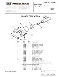
PARTS LIST<br />
2<br />
Pneumatic Remote Control Assembly<br />
(See 3-7840)<br />
(<strong>25</strong>-OA-DUP-<strong>10</strong>-<strong>10</strong>-C Only)<br />
8<br />
3<br />
7<br />
OUTLET<br />
INLET<br />
REQUIREMENTS<br />
<strong>10</strong>00 PSIG (69 BAR)<br />
NET MINIMUM<br />
INLET<br />
9<br />
2000 PSIG (138 BAR)<br />
NET MAXIMUM<br />
RETURN<br />
TO<br />
SOURCE<br />
2.75 GPM (<strong>10</strong>.4 L)<br />
MINIMUM<br />
5.50 GPM (20.8 L)<br />
MAXIMUM<br />
OIL<br />
FROM<br />
SOURCE<br />
<strong>SPX</strong> Corporation, Rockford, IL 61<strong>10</strong>9 USA<br />
http://www.powerteam.c<strong>om</strong><br />
Made in USA<br />
<strong>10</strong>00056<br />
<strong>10</strong><br />
4<br />
11<br />
FOR PRESSURE TO<br />
CONNECTION NO 1<br />
TURN FULLY C-CW<br />
WHEN SELECTOR VALVE KNOB IS TURNED CLOCK-WISE,<br />
PRESSURE IS PRESENT IN BOTH CONNECTOR PORTS.<br />
FOR PRESSURE TO<br />
BOTH<br />
<strong>10</strong>,000 PSIG (690 BAR)<br />
<strong>10</strong>,000 PSIG (690 BAR)<br />
CONNECTIONS<br />
TURN CW CONNECTION No 2<br />
CONNECTION No 1<br />
3-7941Rev2<br />
5<br />
6<br />
HYDRAULIC POWER PUMP <strong>25</strong>-OM-DUP-<strong>10</strong>-C & <strong>25</strong>-OA-DUP-<strong>10</strong>-C<br />
Item Part No. Item Part No.<br />
No. No. Req’d Description No. No. Req’d Description<br />
1 420691 1 Decal, Product Blank<br />
2 50<strong>10</strong>71-OR9 1 Case, (<strong>25</strong> OM/OA Carrying Orange)<br />
3 3-5099 1 Decal, (Truck Oil)<br />
4 <strong>10</strong>00056 1 Decal, (Tradename Power Team)<br />
5 422069-OR9 1 Cover, (<strong>25</strong> OM/OA ORANGE)<br />
6 3-7941 1 Decal, (Tool Outlets)<br />
7 11388 4 Washer, (Tooth Ext .37 x .17)<br />
8 5-1400 4 Screw, Pan Head Mach.<br />
9 3000<strong>10</strong>0 1 Booster Assembly<br />
(<strong>25</strong>-OM-DUP-<strong>10</strong>-<strong>10</strong> Only)<br />
3000<strong>10</strong>1 1 Booster Assembly Remote<br />
(<strong>25</strong>-OA-DUP-<strong>10</strong>-<strong>10</strong> Only)<br />
<strong>10</strong> 11351 4 Washer, (Tooth Ext .50 x .26)<br />
11 <strong>10</strong>450 4 Screw, Mach. Round Slot Head<br />
Sheet No. 3 of 5<br />
Rev Date: 09 Feb 2004
Operating Instructions and Parts List, Form No. <strong>10</strong>00033, Back sheet 3 of 5<br />
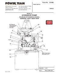
PARTS LIST<br />
4<br />
(<strong>25</strong>-0A-DUP-<strong>10</strong>-<strong>10</strong>-C Only)<br />
13<br />
14<br />
1 2 3 4<br />
9,6,7<br />
<strong>10</strong> 11<br />
12<br />
5.6,7<br />
8<br />
HYDRAULIC POWER PUMP <strong>25</strong>-OM-DUP-<strong>10</strong>-C & <strong>25</strong>-OA-DUP-<strong>10</strong>-C<br />
Item Part No. Item Part No.<br />
No. No. Req’d Description No. No. Req’d Description<br />
1 3-4986 1 Block Assembly, Motor Out<br />
2 FM-<strong>10</strong>02 1 Fluid Motor 5.0 cc<br />
3 3-7740 1 Valve Assembly, Control<br />
4 3-7750 1 Control Assembly, Manual<br />
3-7840 1 Control Assembly, Remote<br />
5 260086 1 Tube<br />
6 5-0529 4 Nut<br />
7 5-0530 4 Ferrule<br />
8 3000099 1 Block Assembly<br />
9 260087 1 Tube<br />
<strong>10</strong> <strong>10</strong>030 1 Screw, Soc.Hd. (5/16-18 x3/4)<br />
11 9797 1 Dust Plug<br />
12 <strong>25</strong>600-1 1 Coupler<br />
13 11127 2 Plug, Shipping<br />
14 5-0545 1 Fitting, Aero-Quip No. 2040-6x6
Operating Instructions and Parts List Form No. <strong>10</strong>00033<br />
PARTS LIST<br />
B<br />
B<br />
A<br />
A<br />
9<br />
8<br />
2<br />
SECTION A-A<br />
12<br />
<strong>10</strong><br />
11<br />
14<br />
3<br />
13<br />
6<br />
4 5<br />
SECTION B-B<br />
7<br />
1<br />
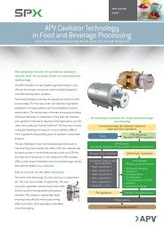
VALVE BLOCK ASSEMBLY 3-7740<br />
Item Part No. Item Part No.<br />
No. No. Req’d Description No. No. Req’d Description<br />
1 3-5593 1 Adapter, Valve Operator<br />
2 3-7741 1 Block, Valve<br />
3 3-7742 1 Plunger, Valve<br />
4 3-7743 1 Rod, Push<br />
5 3-7805 1 Washer, Back-up<br />
6 <strong>10</strong>375 1 Ball<br />
7 <strong>10</strong>264 1 O-Ring<br />
8 <strong>25</strong>1222 1 Plug, Pipe<br />
9 <strong>10</strong>673 1 Nipple<br />
<strong>10</strong> 5-04<strong>25</strong> 1 Screw<br />
11 5-0829 1 Plug, Pipe<br />
12 5-1873 1 Body, Elbow<br />
13 5-33<strong>10</strong> 1 Ring, Retaining<br />
14 5-3336 1 Spring, C<strong>om</strong>pression<br />
Sheet No. 4 of 5<br />
Rev Date: 09 Feb 2004
Operating Instructions and Parts List, Form No. <strong>10</strong>00033, Back sheet 4 of 5<br />
Parts List<br />
1<br />
4<br />
6<br />
5<br />
7<br />
3<br />
2<br />
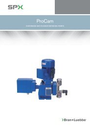
MANUAL CONTROL ASSEMBLY 3-7750<br />
Item Part No. Item Part No.<br />
No. No. Req’d Description No. No. Req’d Description<br />
1 3-0016 1 Knob<br />
2 3-3983 1 Sleeve<br />
3 3-7751 1 Housing<br />
4 3-7752 1 Rod<br />
5 3-7753 1 Plunger<br />
6 5-1268 1 Pin<br />
7 5-2878 1 Spring<br />
1<br />
5<br />
2<br />
3<br />
4<br />
Item Part No. Item Part No.<br />
No. No. Req’d Description No. No. Req’d Description<br />
1 3-7746 1 Control Sub Assembly, Air<br />
2 5-0016 6 Ft. Tubing, Nylon<br />
3 5-0965 1 Bulb, Squeeze<br />
REMOTE CONTROL ASSEMBLY 3-7840<br />
4 5-0967 1 Connector, Barb<br />
5 5-3369 1 Connector, Threaded
Operating Instructions and Parts List Form No. <strong>10</strong>00033<br />
PARTS LIST<br />
A<br />
B<br />
J E<br />
D<br />
F<br />
F<br />
C<br />
C<br />
A<br />
G<br />
B J<br />
E<br />
D<br />
BLOCK ASSEMBLY 3000099<br />
G<br />
1<br />
2<br />
3 4<br />
5<br />
6 16 17 18 19<br />
24<br />
15<br />
7<br />
23<br />
14<br />
11<br />
12<br />
13<br />
SECTION A-A<br />
8 22<br />
9<br />
<strong>10</strong> 21<br />
20<br />
SECTION B-B<br />
31<br />
30<br />
29<br />
28<br />
26 <strong>25</strong><br />
27<br />
SECTION C-C<br />
Item Part No. Item Part No.<br />
No. No. Req’d Description No. No. Req’d Description<br />
1 <strong>10</strong>423 2 Ball, 1/32” Dia. Steel<br />
2 5-2384 2 Spring, C<strong>om</strong>pression<br />
3 5-0829 2 Plug, Pipe<br />
4 3-3381 1 Shaft, Eccentric<br />
5 3-3400 1 Ring Assembly, Bearing<br />
6 16164 2 O-Ring<br />
7 3-3385 2 Plug, Plunger<br />
8 12390 2 Washer, Back-up<br />
9 5-2064 2 Spring, C<strong>om</strong>pression<br />
<strong>10</strong> 3-3399 2 Intake Check Assembly<br />
11 3-3383 1 Washer, Thrust<br />
12 5-0141 1 Bearing, Needle<br />
13 3-2445 1 Ring Assembly, Bearing<br />
14 3-2814 2 Plunger Bushing Set<br />
15 5-1873 1 Body, Elbow<br />
16 <strong>10</strong>377 1 Ball, 5/16” Dia. Steel<br />
17 5-1<strong>10</strong>1 1 Spring, C<strong>om</strong>pression<br />
18 3-4990 1 Plunger, Sump Pump<br />
19 3-7939 1 Pump Block<br />
20 3-5308 1 Intake Check Assembly<br />
21 5-0829 1 Plug, Pipe<br />
22 5-1992 1 Spring, C<strong>om</strong>pression<br />
23 11953 1 Plug, Hex<br />
24 5-0829 2 Plug, Pipe<br />
<strong>25</strong> <strong>10</strong>479 1 Fitting, Plug 1/4 NPTF<br />
26 19543 1 O-Ring<br />
27 3-4991 1 Plunger, Accumulator<br />
28 5-2042 1 Spring, C<strong>om</strong>pression<br />
29 <strong>10</strong>241 4 Lock Washer<br />
30 15122 4 Screw<br />
31 3-4992 1 Cover, Accumulator<br />
Sheet No. 5 of 5<br />
Rev Date: 09 Feb 2004
Operating Instructions and Parts List, Form No. <strong>10</strong>00033, Back sheet 5 of 5<br />
Parts List<br />
33<br />
35 36<br />
34<br />
46<br />
45<br />
39<br />
SECTION D-D<br />
38<br />
37<br />
44<br />
43<br />
40<br />
42<br />
41<br />
SECTION E-E<br />
BLOCK ASSEMBLY 3000099<br />
Item Part No. Item Part No.<br />
No. No. Req’d Description No. No. Req’d Description<br />
33 5-0545 1 Fitting, Adapter<br />
34 <strong>10</strong>378 1 Ball<br />
35 5-2905 1 Spring, C<strong>om</strong>pression<br />
36 5-1906 1 Plug, Hex<br />
37 3-2716 1 Valve Assembly <strong>10</strong>,000 psi<br />
38 3-3388 1 Cover Assembly, Valve<br />
39 5-1873 1 Body, Elbow<br />
40 3-3387 1 Plunger Assembly<br />
41 <strong>25</strong>3035 1 O-Ring<br />
42 3-3386 1 Screw, P.O.<br />
43 5-2155 1 Ring, Back-Up<br />
44 <strong>10</strong>377 1 Ball<br />
45 5-3041 1 Spring<br />
46 5-3055 1 Spring, C<strong>om</strong>pression<br />
57<br />
56<br />
55<br />
54<br />
53<br />
52<br />
62<br />
61<br />
60<br />
47<br />
58<br />
59<br />
50,51 49 48<br />
SECTION F-F SECTION G-G SECTION J-J<br />
BLOCK ASSEMBLY 3000099<br />
Item Part No. Item Part No.<br />
No. No. Req’d Description No. No. Req’d Description<br />
47 5-0829 5 Plug, Pipe<br />
48 5-2901 1 Screw, Set<br />
49 <strong>10</strong>375 1 Ball<br />
50 3-7943 1 Knob, Selector Valve<br />
51 5-2386 1 Pin, 1/8 x 1<br />
52 3-3070 1 Sub-Assembly, Shaft/Housing<br />
53 16164 1 O-Ring<br />
54 <strong>25</strong>1222 1 Plug, Pipe<br />
55 12223 1 Ball, 3/16” Dia. Steel<br />
56 3-1369 1 Spring, C<strong>om</strong>pression<br />
57 5-0545 1 Fitting, Adapter<br />
58 3-3388 1 Cover Assembly, Valve<br />
59 3-2716 1 Valve Assembly, <strong>10</strong>,000 psi<br />
60 <strong>10</strong>377 1 Ball<br />
61 5-3582 1 Spring, C<strong>om</strong>pression<br />
62 5-0829 1 Plug, Pipe