model 25-om-dup-10/10-c & 25-oa-dup-10/10-c hydraulic ... - SPX
model 25-om-dup-10/10-c & 25-oa-dup-10/10-c hydraulic ... - SPX
model 25-om-dup-10/10-c & 25-oa-dup-10/10-c hydraulic ... - SPX

Create successful ePaper yourself
Turn your PDF publications into a flip-book with our unique Google optimized e-Paper software.
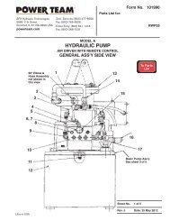
Operating Instructions and Parts List, Form No. <strong>10</strong>00033<br />
OPERATING INSTRUCTIONS<br />
The booster is ready for operation upon leaving the warehouse.<br />
• Locate hole marked “inlet” on front of metal case. Remove metal plug. Connect out-put (pressure) line fr<strong>om</strong><br />
supply system.<br />
• Locate hole marked “outlet” on front of metal case. Remove metal plug and connect return (tank) line fr<strong>om</strong><br />
supply system.<br />
• Connect the tool line to the proper port equipped with a quick coupler.<br />
• The control lever on the control valve is spring l<strong>oa</strong>ded to valve “OFF” position.<br />
• Check tightness of hose connections and be sure quick coupler is c<strong>om</strong>pletely engaged with coupler on tool line.<br />
• The supply system can now be operated.<br />
• When control lever is pulled back fully to “ON” position, the booster begins to build pressure in the tool line.<br />
• When tool line pressure reaches the relief valve setting, an audible popping will be heard, indicating that no<br />
higher pressure can be obtained.<br />
• Move control lever to “OFF” by releasing lever. In “OFF” position, the tool line will aut<strong>om</strong>atically exhaust to the<br />
supply truck tank.<br />
The greatest single cause of failure in <strong>hydraulic</strong> boosters is dirt. Extreme caution should<br />
be exercised to prevent the introduction of foreign matter into the unit.<br />
SERVICING INSTRUCTIONS<br />
HIGH PRESSURE VALVE ADJUSTMENT<br />
The high pressure relief valve assembly determines the maximum pressure developed by the booster. The valve is<br />
factory set to <strong>10</strong>,000 PSI as required.<br />
IMPORTANT<br />
If by use of a pressure gauge installed in the tool line, it is determined that the pressure<br />
setting is incorrect, check tool and all connections for leaks before adjusting valve.<br />
To gain access to the valve, remove pump fr<strong>om</strong> the carrying case. Disassemble the valve cover assembly (Key No.<br />
38 & 58) by removing the two flat head screws and cover plate. Insert a #<strong>10</strong>-32 screw into threaded hole in center of<br />
sealing disc and pull disc out of hole in pump block. End of relief valve assembly can now be seen. Remove valve<br />
using Power Team Valve removal tool (Part No. 3-4172) available fr<strong>om</strong> factory or Power Team distributors. To adjust<br />
valve, use a short 5/64 hex socket key to loosen set screw shown on side of valve assembly. To increase pressure,<br />
use a screwdriver to turn slotted adjusting screw clockwise deeper into valve body or counter-clockwise out of body to<br />
decrease pressure. Pressure will change at a rate of approximately 1,000 PSI per 1/8 turn of adjusting screw. After<br />
making adjustment, re-tighten locking set screw securely, re-assemble disc and cover using care not to cut o-ring on<br />
disc and re-check pressure as before.<br />
C<strong>om</strong>patible Hydraulic Fluids:<br />
The use of Amoco Rykon MV oil is rec<strong>om</strong>mended. C<strong>om</strong>patible fluids include:<br />
Mobil DTE 13<br />
Mobil ATF 220<br />
Shell Tellus 32<br />
Arco Dexron III<br />
Citgo AW32<br />
Citgo Dexron III<br />
Other fluids also may be used if they meet or exceed the following specifications:<br />
Viscosity: 180 SSU at <strong>10</strong>0 degree F.<br />
Flash Point: 350 degree F<br />
Pour Point: -50 degree F<br />
Sheet No. 2 of 5<br />
Rev Date: 09 Feb 2004