Dynamics - Audiofanzine
Dynamics - Audiofanzine
Dynamics - Audiofanzine

Create successful ePaper yourself
Turn your PDF publications into a flip-book with our unique Google optimized e-Paper software.
DS-15<br />
<strong>Dynamics</strong><br />
<br />
Introduction<br />
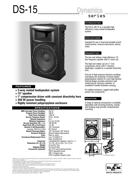
The D.A.S. DS-15 is a versatile high<br />
efficiency 2-way vented loudspeaker<br />
system.<br />
Applications<br />
Intended for use in fixed and portable sound<br />
reinforcement, musical instruments, discos,<br />
clubs.<br />
Description<br />
The low end utilizes a high efficiency 15"<br />
low frequency speaker with 3" voice coil.<br />
The high end makes use of a 1" exit<br />
compression driver with 2" titanium<br />
diaphragm, coupled to a constant directivity<br />
horn.<br />
FEATURES<br />
» 2-way vented loudspeaker system<br />
» 15" speaker<br />
» 1" compression driver with constant directivity horn<br />
» 350 W power handling<br />
» Highly resistant polypropylene enclosure<br />
RMS (Average) Power Handling R :<br />
Program Power Handling P :<br />
Peak Power Handling K :<br />
On-axis Frequency Range F :<br />
Nominal Impedance:<br />
Minimum Impedance I :<br />
On-axis Sensitivity 1W / 1 m S :<br />
Rated Peak SPL at Full Power:<br />
Nominal -6 dB Beamwidths B :<br />
(average, 500 Hz to 8 kHz)<br />
Speech Coverage Angles C :<br />
Enclosure Material:<br />
Color:<br />
Transducers/Replacement Parts:<br />
SPECIFICATIONS<br />
Connector:<br />
Dimensions (H x W x D):<br />
Weight:<br />
Shipping Weight:<br />
Accessories (optional):<br />
350 W<br />
700 W<br />
1400 W<br />
50 Hz - 20 kHz<br />
8 Ω<br />
6 Ω (at 15 kHz)<br />
100 dB SPL<br />
131 dB<br />
100° Horizontal<br />
80° Vertical<br />
105° Horizontal x 80° Vertical<br />
Mineral loaded polypropylene<br />
Black or white<br />
Low: P-15/GM P-15<br />
High: M-5/GM M-5<br />
2 paralleled NL4 Speakon, wired to ±1<br />
70 x 45 x 36 cm (28 x 18 x 15 in)<br />
23 kg (50.7 lbs)<br />
24.5 kg (54 lbs)<br />
AX-12/15 wall mounting bracket<br />
TRD-2 adjustable tripod<br />
ANL-1 hanging rings<br />
FUN-15 padded transport cover<br />
Full use of high pressure injection moulding<br />
techniques has achieved a mineral loaded<br />
polypropylene cabinet of a very high density.<br />
Internal design provides extensive wall<br />
reinforcing for minimum vibration. A<br />
moulded-in handle facilitates carrying.<br />
For added resistance, rugged steel grilles<br />
protect the components.<br />
Mounting<br />
A range of optional accessories is available:<br />
adjustable wall mounting brackets, tripods<br />
and hanging rings provide comprehensive<br />
mounting.<br />
444<br />
147<br />
690<br />
165<br />
360<br />
ALL DIMENSIONS IN MILIMETERS<br />
R Based on a 2 hour test using a 6 dB crest factor pink noise signal bandlimited according to IEC 268-1 (1985). All power ratings are referred<br />
to the nominal impedance.<br />
P Conventionally 3 dB higher than the RMS measure, although this already utilizes a program signal.<br />
K Corresponds to the signal crests for the test described in R .<br />
F As per IEC 268-5 (1989), re. a two octave band centred at 2 kHz. Half space anechoic.<br />
I In practice cable and connector impedance has to be added to all impedance values.<br />
S For the 2 kHz one octave band.<br />
B Average of one-third octave band measures.<br />
C There is currently no standard method of averaging the beamwidth with frequency characteristics into a single meaningful figure, which<br />
impedes comparisons across manufacturers and very often even product lines. This, our own, criterion weighs the -6 dB coverage angles<br />
from one-octave bands according to their contribution to speech intelligibility.<br />
One and one-third octave bands comply to ANSI S1.11-1986.
DS-15<br />
Frequency Response<br />
Figure 1 shows the frequency response at 1 m<br />
of a unit radiating to a half space anechoic environment<br />
and driven by a 1 W (2.83 V) swept<br />
sine signal.<br />
Impedance<br />
Figure 2 shows impedance with frequency.<br />
Distortion<br />
Figure 3 shows the Total Harmonic Distortion<br />
Plus Noise (solid), Second Harmonic Distortion<br />
(grey) and Third Harmonic Distortion (dotted)<br />
curves for a unit driven at 30W.<br />
Beamwidth<br />
Figure 4 shows the -3, -6 and -10 dB horizontal<br />
(solid) and vertical (dashed) beamwidth with<br />
frequency curves. -6 dB ones are shown with<br />
thicker traces for clarity.<br />
Axial Directivity Q(R θ ) and Di<br />
Figure 5 shows the above characteristics with<br />
frequency. Thin continuous and dashed lines<br />
show partial horizontal and vertical,<br />
respectively, characteristics.<br />
Polar Response<br />
Figure 6 shows the one octave band horizontal<br />
(solid) and vertical (dashed) polars for the<br />
indicated frequencies. Full scale is 50 dB, 5 dB<br />
per division.<br />
NOTES. 1.Frequency response: referred to 1 m; low end<br />
obtained through the use of near field techniques; one-third<br />
octave smoothed for correlation with human hearing. 2.In<br />
practice, cable and connector impedance need to be added.<br />
3.Harmonic distortion components are not plotted beyond 20<br />
kHz; near-field techniques used. 4.Directivity characteristics<br />
plotted with respect to frequency are the average within the<br />
one-third octave bands of center frequencies noted by the<br />
marks at the bottom of the graphs, but are joined up for<br />
display purposes. All other characteristics plotted vs.<br />
frequency use 1/24th octave resolution. Regions of less than<br />
1 dB below goal level and sharp notches may be ignored<br />
when calculating beamwidths. 5.Directivity factor and index<br />
were computed from two degree resolution vertical and<br />
horizontal polars using sinusoidal weighting. 6.Polars were<br />
acquired by placing the unit on a computer controlled<br />
turntable inside our anechoic chamber. Measurement<br />
distance was 4 m.<br />
Product improvement through research and development is<br />
a continuous process at D.A.S. Audio. All specifications<br />
subject to change without notice.<br />
FIG. 5<br />
FIG. 4<br />
FIG. 3<br />
FIG. 2<br />
FIG. 1<br />
SPL in dB<br />
impedance in<br />
distortion in dB<br />
directivity index Di in dB<br />
110<br />
100<br />
90<br />
80<br />
70<br />
60<br />
20 50 100 200<br />
500 1k 2k<br />
5k 10k 20k 40k<br />
frequency in Hz<br />
200<br />
100<br />
50<br />
20<br />
10<br />
5<br />
2<br />
1<br />
20 50 100 200<br />
500 1k 2k<br />
5k 10k 20k 40k<br />
frequency in Hz<br />
0<br />
100<br />
-10<br />
-20<br />
30<br />
10<br />
-30<br />
-40<br />
-50<br />
3<br />
1<br />
.3<br />
20 50 100 200<br />
500 1k 2k<br />
5k 10k 20k 40k<br />
frequency in Hz<br />
200<br />
100<br />
50<br />
20<br />
10<br />
5<br />
20 50 100 200<br />
500 1k 2k<br />
5k 10k 20k 40k<br />
frequency in Hz<br />
beamwidth in degrees300<br />
25<br />
20<br />
15<br />
10<br />
vertical<br />
horizontal<br />
5<br />
5<br />
0<br />
1<br />
20 50 100 200<br />
500 1k 2k<br />
5k 10k 20k 40k<br />
frequency in Hz<br />
200<br />
100<br />
50<br />
20<br />
10<br />
distortion in %<br />
directivity factor Q (R )<br />
<br />
D.A.S. Audio, S.A.<br />
C/. Islas Baleares, 24 - 46988 Fuente del Jarro - Valencia, SPAIN<br />
Tel. 96 134 0525 - Tel. Intl. +34 96 134 0860 - Fax. 96 134 0607 - Fax. Intl. +34 96 134 06 07<br />
D.A.S. Audio of<br />
America, Inc.<br />
6970 N.W. 50th St. Miami, FL 33166, U.S.A.<br />
Tel. +1 305 436 0521 - Fax. +1 305 436 0528<br />
http://www.dasaudio.com<br />
TE/036-03<br />
02/2001