Salt Disposal of Heat-Generating Nuclear Waste
Salt Disposal of Heat-Generating Nuclear Waste
Salt Disposal of Heat-Generating Nuclear Waste

Create successful ePaper yourself
Turn your PDF publications into a flip-book with our unique Google optimized e-Paper software.
SANDIA REPORT<br />
SAND2011-0161<br />
Unlimited Release<br />
Printed January 2011<br />
<strong>Salt</strong> <strong>Disposal</strong> <strong>of</strong> <strong>Heat</strong>-<strong>Generating</strong><br />
<strong>Nuclear</strong> <strong>Waste</strong><br />
Frank D. Hansen and Christi D. Leigh<br />
Prepared by<br />
Sandia National Laboratories<br />
Albuquerque, New Mexico 87185 and Livermore, California 94550<br />
Sandia National Laboratories is a multiprogram laboratory managed and operated by Sandia Corporation,<br />
a wholly owned subsidiary <strong>of</strong> Lockheed Martin Corporation, for the U.S. Department <strong>of</strong> Energy's<br />
National <strong>Nuclear</strong> Security Administration under contract DE-AC04-94AL85000.<br />
Approved for public release; further dissemination unlimited.
Issued by Sandia National Laboratories, operated for the United States Department <strong>of</strong> Energy<br />
by Sandia Corporation.<br />
NOTICE: This report was prepared as an account <strong>of</strong> work sponsored by an agency <strong>of</strong> the<br />
United States Government. Neither the United States Government, nor any agency there<strong>of</strong>, nor<br />
any <strong>of</strong> their employees, nor any <strong>of</strong> their contractors, subcontractors, or their employees, make<br />
any warranty, express or implied, or assume any legal liability or responsibility for the<br />
accuracy, completeness, or usefulness <strong>of</strong> any information, apparatus, product, or process<br />
disclosed, or represent that its use would not infringe privately owned rights. Reference herein<br />
to any specific commercial product, process, or service by trade name, trademark,<br />
manufacturer, or otherwise, does not necessarily constitute or imply its endorsement,<br />
recommendation, or favoring by the United States Government, any agency there<strong>of</strong>, or any <strong>of</strong><br />
their contractors or subcontractors. The views and opinions expressed herein do not<br />
necessarily state or reflect those <strong>of</strong> the United States Government, any agency there<strong>of</strong>, or any<br />
<strong>of</strong> their contractors.<br />
Printed in the United States <strong>of</strong> America. This report has been reproduced directly from the best<br />
available copy.<br />
Available to DOE and DOE contractors from<br />
U.S. Department <strong>of</strong> Energy<br />
Office <strong>of</strong> Scientific and Technical Information<br />
P.O. Box 62<br />
Oak Ridge, TN 37831<br />
Telephone: (865) 576-8401<br />
Facsimile: (865) 576-5728<br />
E-Mail: reports@adonis.osti.gov<br />
Online ordering: http://www.osti.gov/bridge<br />
Available to the public from<br />
U.S. Department <strong>of</strong> Commerce<br />
National Technical Information Service<br />
5285 Port Royal Rd.<br />
Springfield, VA 22161<br />
Telephone: (800) 553-6847<br />
Facsimile: (703) 605-6900<br />
E-Mail: orders@ntis.fedworld.gov<br />
Online order: http://www.ntis.gov/help/ordermethods.asp?loc=7-4-0#online
SAND2011-0161<br />
Unlimited Release<br />
Printed January 2011<br />
<strong>Salt</strong> <strong>Disposal</strong> <strong>of</strong> <strong>Heat</strong>-<strong>Generating</strong> <strong>Nuclear</strong> <strong>Waste</strong><br />
Frank D. Hansen and Christi D. Leigh<br />
Frank D. Hansen<br />
Christi D. Leigh<br />
MS 0751 Org 6914 MS 1395 Org 6212<br />
Sandia National Laboratories<br />
Sandia National Laboratories<br />
P.O. Box 5800<br />
4100 National Parks Highway<br />
Albuquerque, NM 87185-0778 Carlsbad, NM 88220<br />
ABSTRACT<br />
This report summarizes the state <strong>of</strong> salt repository science, reviews many <strong>of</strong> the technical issues<br />
pertaining to disposal <strong>of</strong> heat-generating nuclear waste in salt, and proposes several avenues for<br />
future science-based activities to further the technical basis for disposal in salt. There are<br />
extensive salt formations in the forty-eight contiguous states, and many <strong>of</strong> them may be worthy<br />
<strong>of</strong> consideration for nuclear waste disposal. The United States has extensive experience in salt<br />
repository sciences, including an operating facility for disposal <strong>of</strong> transuranic wastes. The<br />
scientific background for salt disposal including laboratory and field tests at ambient and<br />
elevated temperature, principles <strong>of</strong> salt behavior, potential for fracture damage and its mitigation,<br />
seal systems, chemical conditions, advanced modeling capabilities and near-future<br />
developments, performance assessment processes, and international collaboration are all<br />
discussed. The discussion <strong>of</strong> salt disposal issues is brought current, including a summary <strong>of</strong><br />
recent international workshops dedicated to high-level waste disposal in salt.<br />
Lessons learned from Sandia National Laboratories’ experience on the <strong>Waste</strong> Isolation Pilot<br />
Plant and the Yucca Mountain Project as well as related salt experience with the Strategic<br />
Petroleum Reserve are applied in this assessment. <strong>Disposal</strong> <strong>of</strong> heat-generating nuclear waste in a<br />
suitable salt formation is attractive because the material is essentially impermeable, self-sealing,<br />
and thermally conductive. Conditions are chemically beneficial, and a significant experience<br />
base exists in understanding this environment. Within the period <strong>of</strong> institutional control,<br />
overburden pressure will seal fractures and provide a repository setting that limits radionuclide<br />
movement. A salt repository could potentially achieve total containment, with no releases to the<br />
environment in undisturbed scenarios for as long as the region is geologically stable. Much <strong>of</strong> the<br />
experience gained from United States repository development, such as seal system design,<br />
coupled process simulation, and application <strong>of</strong> performance assessment methodology, helps<br />
define a clear strategy for a heat-generating nuclear waste repository in salt.<br />
iii
ACKNOWLEDGMENTS<br />
Sandia is a multiprogram laboratory managed and operated by Sandia Corporation, a wholly<br />
owned subsidiary <strong>of</strong> Lockheed Martin Corporation, for the U.S. Department <strong>of</strong> Energy’s<br />
National <strong>Nuclear</strong> Security Administration under Contract DE-AC04-94AL85000.<br />
The authors are indebted to our German colleagues, who provided encouragement and support<br />
for renewed collaboration in salt repository sciences. This document benefitted from extensive<br />
review and input from several experts in the field. Although the content is the responsibility <strong>of</strong><br />
the authors, it has been improved by review and comments from Roger Nelson, Norbert Rempe,<br />
Leif Eriksson, and Wendell Weart.<br />
iv
CONTENTS<br />
1 Introduction ............................................................................................................................... 1<br />
1.1 Background and Regulatory Framework ......................................................................... 2<br />
1.2 <strong>Salt</strong> Formations in the United States ................................................................................ 5<br />
1.3 History <strong>of</strong> <strong>Salt</strong> <strong>Disposal</strong> Research for <strong>Heat</strong>-<strong>Generating</strong> <strong>Nuclear</strong> <strong>Waste</strong> ......................... 8<br />
1.4 Analogues for <strong>Salt</strong> <strong>Disposal</strong>........................................................................................... 10<br />
2 Technical Basis And Characterization .................................................................................... 15<br />
2.1 <strong>Nuclear</strong> <strong>Waste</strong> Characteristics ....................................................................................... 15<br />
2.2 <strong>Salt</strong> Repository Design .................................................................................................. 18<br />
2.2.1 Concept <strong>of</strong> <strong>Disposal</strong> for HLW in <strong>Salt</strong> .............................................................. 19<br />
2.3 Seals ............................................................................................................................... 20<br />
2.4 Thermal-Hydrologic-Mechanical Conditions in the Host Rock .................................... 24<br />
2.4.1 Excavation/Construction Effects ...................................................................... 24<br />
2.4.2 Thermal Effects ................................................................................................ 34<br />
2.4.3 Coupled Thermal-Hydrologic-Mechanical Effects .......................................... 37<br />
2.5 Chemical Conditions in the Host Rock .......................................................................... 42<br />
2.5.1 The Thermal Period .......................................................................................... 42<br />
2.5.2 After the Thermal Period .................................................................................. 44<br />
2.5.3 State-<strong>of</strong>-the-Art Geochemical Modeling .......................................................... 47<br />
2.5.4 Coupled Reactive Transport Modeling ............................................................ 49<br />
2.5.5 Radionuclide Transport .................................................................................... 49<br />
2.5.6 International Collaboration on <strong>Salt</strong> Repository Chemistry .............................. 49<br />
3 Performance Analysis for HLW <strong>Disposal</strong> In <strong>Salt</strong> ................................................................... 51<br />
3.1 Identification <strong>of</strong> Relevant Features, Events, and Processes ........................................... 52<br />
3.1.1 Catalogs <strong>of</strong> FEPs .............................................................................................. 53<br />
3.2 Scenario Selection .......................................................................................................... 54<br />
3.2.1 Scenario for an Isothermal “Cool” <strong>Salt</strong> Repository ......................................... 54<br />
3.2.2 Scenario for a Thermal “Hot” <strong>Salt</strong> Repository ................................................. 54<br />
3.2.3 Important FEPs for a “Hot” <strong>Salt</strong> Repository .................................................... 56<br />
4 A Performance-Based Directed Research Program ................................................................ 57<br />
4.1 Thermal-Hydrologic-Mechanical Response <strong>of</strong> <strong>Salt</strong>....................................................... 58<br />
4.2 DRZ Evolution and Healing .......................................................................................... 58<br />
4.3 Consolidation <strong>of</strong> Backfill Materials at Elevated Temperature ...................................... 59<br />
4.4 Availability and Movement <strong>of</strong> Brine and Vapor Phases ............................................... 60<br />
4.5 Geochemical Environment............................................................................................. 60<br />
4.6 Radionuclide Solubility Controls and Transport Mechanisms ...................................... 61<br />
4.7 Findings <strong>of</strong> the U.S./German Workshop on <strong>Salt</strong> Repository Research, Design and<br />
Operation........................................................................................................................ 61<br />
4.7.1 Description <strong>of</strong> the Work ................................................................................... 62<br />
4.7.2 Future Direction ............................................................................................... 64<br />
5 Summary and Recommendations ........................................................................................... 67<br />
5.1 Summary <strong>of</strong> Findings ..................................................................................................... 67<br />
5.2 Recommendations for Continued Research ................................................................... 69<br />
v
5.3 Laboratory Studies ......................................................................................................... 71<br />
5.4 Modeling and Simulation ............................................................................................... 72<br />
5.5 International Collaboration ............................................................................................ 73<br />
5.6 Field Tests ...................................................................................................................... 73<br />
6 References ............................................................................................................................... 75<br />
Appendix A: Baseline Features, Events, and Processes (FEPs) List For <strong>Salt</strong> <strong>Disposal</strong> ............... 85<br />
FIGURES<br />
Figure 1. <strong>Salt</strong> deposits in the United States (Johnson and Gonzales 1978). ................................ 6<br />
Figure 2. Decay chains <strong>of</strong> the actinide elements for HLW isotopes .......................................... 16<br />
Figure 3. <strong>Disposal</strong> operations for TRU waste at the WIPP ....................................................... 18<br />
Figure 4. DRZ development and healing around a disposal room<br />
(from Park and Holland 2007) .................................................................................... 34<br />
Figure 5. Temperature effects on salt creep ............................................................................... 35<br />
Figure 6. Deformed salt samples and their microstructure (Hansen 2010) ................................ 36<br />
Figure 7. Temperature in the deformed salt repository at 27 years (Stone et al. 2010) ............. 40<br />
Figure 8. Porosity in the crushed salt backfill at 27 years, from an initial porosity <strong>of</strong> 0.42<br />
(Stone et al. 2010) ....................................................................................................... 40<br />
Figure 9. SNL long-term Performance Assessment methodology. ........................................... 52<br />
Figure 10. Gap analysis for a HLW repository in salt.................................................................. 57<br />
TABLES<br />
Table 1. <strong>Salt</strong> mines in the continental United States................................................................... 7<br />
Table 2. Qualitative comparison <strong>of</strong> geologic media as HLW repository host .......................... 13<br />
Table 3. Chemical elements to be considered in a HLW chemical model ............................... 17<br />
Table 4. Areas <strong>of</strong> interest and possible assessment methods .................................................... 70<br />
vi
NOMENCLATURE<br />
CFR<br />
DOE<br />
DRZ<br />
EPA<br />
FEP<br />
HLW<br />
IRZ<br />
NAS<br />
NRC<br />
NWPA<br />
PA<br />
SNL<br />
THM<br />
TRU<br />
UNF<br />
WIPP<br />
Code <strong>of</strong> Federal Regulations<br />
U.S. Department <strong>of</strong> Energy<br />
disturbed-rock zone<br />
U.S. Environmental Protection Agency<br />
feature, event, or process<br />
high-level waste<br />
isolation rock zone<br />
National Academy <strong>of</strong> Sciences<br />
U.S. <strong>Nuclear</strong> Regulatory Commission<br />
<strong>Nuclear</strong> <strong>Waste</strong> Policy Act<br />
performance assessment<br />
Sandia National Laboratories<br />
thermal-hydrologic-mechanical<br />
transuranic waste<br />
used nuclear fuel<br />
<strong>Waste</strong> Isolation Pilot Plant<br />
vii
viii
1 INTRODUCTION<br />
While the need for increased use <strong>of</strong> nuclear power in the United States (U.S.) has<br />
been recognized, the questions <strong>of</strong> when and how to dispose <strong>of</strong> the resulting used<br />
nuclear fuel (UNF) 1 and high-level nuclear waste (HLW), a necessary last step in<br />
the cradle-to-grave philosophy <strong>of</strong> radioactive waste management, still eludes<br />
satisfactory answers. In the 1987 amendment to the <strong>Nuclear</strong> <strong>Waste</strong> Policy Act <strong>of</strong><br />
1982 (NWPA), Congress selected Yucca Mountain in Nevada to characterize for<br />
waste disposal <strong>of</strong> UNF and HLW. Over the next 21 years, the U.S. Department <strong>of</strong><br />
Energy (DOE) investigated the site, evaluated its feasibility, confirmed its<br />
viability (DOE 1998), made a site recommendation (DOE 2002a, 2002b, 2002c),<br />
and prepared a license application for construction authorization (DOE 2008a).<br />
The license application was submitted to the U.S. <strong>Nuclear</strong> Regulatory<br />
Commission (NRC) in June 2008 and docketed for review that September. In<br />
2009 during the NRC review <strong>of</strong> the license application, the Obama<br />
Administration recommended and Congress provided funding only for answering<br />
NRC questions as they prepared their Safety Evaluation Report. All other<br />
activities ceased. In 2010, the DOE formed the Blue Ribbon Commission on<br />
America’s <strong>Nuclear</strong> Future. The DOE has filed a motion to withdraw the license<br />
application, which is under legal review, but the project has nevertheless been<br />
totally disbanded.<br />
Given the developments at the Yucca Mountain Project, it is prudent to anticipate<br />
that the U.S. will begin the process <strong>of</strong> developing a new radioactive waste<br />
management policy. Many <strong>of</strong> the policy issues debated in the 1970s and early<br />
1980s will be revisited. The public debate over UNF/HLW disposal will focus on<br />
potential reprocessing, interim storage, geologic disposal, and repository siting,<br />
particularly with regard to environmental justice and intergenerational equity.<br />
While certain alternatives being discussed, like reprocessing <strong>of</strong> UNF and/or<br />
interim storage would change the volume and/or radioactivity <strong>of</strong> waste needing<br />
disposal, there will ultimately be a residual fraction <strong>of</strong> the waste stream that must<br />
be permanently disposed. This residual fraction <strong>of</strong> waste will be high-heatgenerating,<br />
chemically active, radioactive waste. Geologies for permanent deep<br />
disposal <strong>of</strong> HLW, like shale, granite, clay, and salt, have been proposed over the<br />
years both in the U.S. and in other countries. All <strong>of</strong> these geologic formations or<br />
geologic media exist in the U.S., but a suitable site for disposal <strong>of</strong> HLW has yet to<br />
be chosen (other than Yucca Mountain).<br />
From a study <strong>of</strong> the historical approach toward selecting a HLW disposal site,<br />
DeKay (1999) has suggested three patterns in the national management <strong>of</strong> nuclear<br />
waste. First, concerns over water are an integral component <strong>of</strong> the public’s fear <strong>of</strong><br />
nuclear waste in geologic media, and this fear has impacted the search for a<br />
1 With the current reevaluation <strong>of</strong> reprocessing in the United States, the term used nuclear fuel<br />
(UNF) has supplanted spent nuclear fuel (SNF) as the preferred terminology for fuel discharged<br />
from a nuclear reactor. In this document, the term high-level waste (HLW) is used to denote heatgenerating<br />
nuclear waste.<br />
1
suitable repository site. Second, according to DeKay (1999) there are always<br />
other immediate concerns that take precedence over the nuclear waste issue.<br />
Third, nuclear-waste-management decisions are based on political expediency<br />
rather than making long-term decisions for developing a nuclear waste repository.<br />
While in 1987 Yucca Mountain was selected as the sole site for the potential<br />
development <strong>of</strong> a repository, its selection has been controversial. Therefore, while<br />
a technical commentary can be provided regarding the adequacy <strong>of</strong> each geologic<br />
medium for permanent disposal <strong>of</strong> HLW, the ultimate decision will be a social<br />
and political one involving the disposal location or locations.<br />
Sandia National Laboratories (SNL) has conducted performance analyses for<br />
disposal <strong>of</strong> HLW in deep boreholes basement rock (Brady et al. 2009) and in a<br />
mined geologic repository in clay/shale (Hansen et al. 2010) and has a long<br />
history <strong>of</strong> performance-assessment analyses for disposal <strong>of</strong> non-heat-generating<br />
waste in salt. This report contributes to the national discussion regarding geologic<br />
disposal by synthesizing technical information regarding salt disposal <strong>of</strong> HLW. It<br />
agrees with a well-known study by the National Academy <strong>of</strong> Sciences National<br />
Research Council in the 1950s (National Academy <strong>of</strong> Sciences Committee on<br />
<strong>Waste</strong> <strong>Disposal</strong> 1957) that states,<br />
The most promising method <strong>of</strong> disposal <strong>of</strong> high level waste at the<br />
present time seems to be in salt deposits. The great advantage here is<br />
that no water can pass through the salt. Fractures are self-sealing…<br />
Over time, a considerable body <strong>of</strong> research has been conducted to advance the<br />
state <strong>of</strong> knowledge with respect to waste isolation in salt. The work embodied in<br />
this report further amplifies that salt is a viable geologic setting for permanent<br />
waste isolation in the U.S. Much scientific and technical knowledge about<br />
disposal in salt has accumulated since the initial conclusions made by the National<br />
Academy <strong>of</strong> Sciences. This report updates the technical basis for disposal in salt<br />
and discusses the performance issues that should be addressed when considering<br />
disposal <strong>of</strong> HLW in salt.<br />
1.1 Background and Regulatory Framework<br />
To evaluate the performance <strong>of</strong> any potential repository and decide whether to<br />
proceed with a disposal concept, it is necessary to adopt or develop a regulatory<br />
standard by which the performance <strong>of</strong> the site can be measured. This section<br />
provides background information about development <strong>of</strong> pertinent regulations for<br />
radioactive waste disposal to date and establishes the general regulatory<br />
framework that is considered in this report.<br />
The search for permanent disposal for radioactive waste began in 1955 when the<br />
Atomic Energy Commission (AEC), predecessor agency to the Energy Research<br />
and Development Agency and the DOE, asked the National Research Council <strong>of</strong><br />
the National Academy <strong>of</strong> Sciences to examine the disposal issue. In 1957, the<br />
National Academy <strong>of</strong> Sciences Committee on <strong>Waste</strong> <strong>Disposal</strong> (1957) reported<br />
2
that deep geologic disposal in salt formations was the most promising method to<br />
explore for disposing <strong>of</strong> HLW resulting from reprocessing <strong>of</strong> UNF. The National<br />
Academy <strong>of</strong> Sciences reaffirmed that position in 1961 and 1970 (NAS-NRC 1961;<br />
National Academy <strong>of</strong> Sciences Committee on <strong>Waste</strong> <strong>Disposal</strong> 1970).<br />
By 1974, the AEC’s regulatory programs had come under attack, and Congress<br />
decided to abolish the agency. Supporters and critics <strong>of</strong> nuclear power agreed that<br />
the promotional and regulatory duties <strong>of</strong> the AEC should be assigned to different<br />
agencies. The Energy Reorganization Act <strong>of</strong> 1974 created the <strong>Nuclear</strong> Regulatory<br />
Commission (NRC); it began operations on January 19, 1975. The NRC focused<br />
its attention on several broad issues that were essential to protecting public health<br />
and safety. The promotional duties <strong>of</strong> the AEC were later incorporated into the<br />
DOE when it was established in 1977.<br />
The <strong>Nuclear</strong> <strong>Waste</strong> Policy Act <strong>of</strong> 1982 (NWPA) created a timetable and<br />
procedure for establishing a permanent underground repository for UNF and<br />
HLW from civilian nuclear reactors. Congress assigned responsibility to the DOE<br />
to site, construct, operate, and close a repository for the disposal <strong>of</strong> UNF and<br />
HLW. The U.S. Environmental Protection Agency (EPA) was directed to set<br />
public health and safety standards for releases <strong>of</strong> radioactive materials from a<br />
repository, and the NRC was required to promulgate regulations governing<br />
construction, operation, and closure <strong>of</strong> a repository.<br />
In 1986, the DOE selected three candidate sites for HLW disposal, each in<br />
different geologic media: basalt at the Hanford Reservation, Washington; volcanic<br />
tuff at Yucca Mountain, Nevada; and bedded salt at Deaf Smith County, Texas<br />
(DOE 1986). In 1987, Yucca Mountain was specified 2 as the sole site for the<br />
potential development <strong>of</strong> a HLW repository. Over the next 21 years, the U.S.<br />
continued site investigations, conducted performance assessment (PA), supported<br />
modeling activities, and started design for a repository at Yucca Mountain.<br />
In the meantime, the EPA standard 40 CFR 191 was promulgated. 3 In 40 CFR<br />
191, the primary performance criterion is the cumulative release <strong>of</strong> radionuclides,<br />
and its measure is the mean complementary cumulative distribution function <strong>of</strong><br />
the cumulative release <strong>of</strong> radionuclides that reach the accessible environment<br />
within ten thousand years after disposal, normalized by (a) EPA-derived limits for<br />
specified radionuclides and (b) the mass <strong>of</strong> radionuclides placed in the repository.<br />
The risk <strong>of</strong> release is limited to be the same or less than that posed by the ore<br />
body from which the radioactive material was produced.<br />
2 The 1987 amendments to the NWPA restrict consideration <strong>of</strong> geologic repositories in the U.S. to<br />
a single site in volcanic tuff at Yucca Mountain in Nevada.<br />
3 The EPA also passed 10 CFR 194, Criteria for the Certification and Re-Certification <strong>of</strong> the<br />
<strong>Waste</strong> Isolation Pilot Plant’s Compliance with the 40 CFR Part 191 <strong>Disposal</strong> Regulations, which<br />
is not discussed here because it is specific to the <strong>Waste</strong> Isolation Pilot Plant and transuranic<br />
wastes.<br />
3
Also, the NRC promulgated 10 CFR 60, <strong>Disposal</strong> <strong>of</strong> High-Level Radioactive<br />
<strong>Waste</strong>s in Geologic Repositories. 4 Specific technical criteria are addressed in<br />
Subpart E <strong>of</strong> 10 CFR 60, including various categories such as performance<br />
objectives, siting criteria, design criteria for repository operations, and design<br />
criteria for the waste package. Under these regulations, the waste package is<br />
required to contain HLW for a period between 300 and 1,000 years after closure<br />
<strong>of</strong> the repository. The repository must not allow annual radionuclide releases in<br />
excess <strong>of</strong> one part in 100,000 <strong>of</strong> the inventory <strong>of</strong> radionuclides calculated to be<br />
present at 1,000 years from closure. Also, pre-emplacement groundwater travel<br />
time along the fastest path <strong>of</strong> likely radionuclide travel to the accessible<br />
environment must be more than 1,000 years. Neither 40 CFR 191 nor 10 CFR 60<br />
is a dose-based standard.<br />
In 1995, the National Research Council <strong>of</strong> the National Academies <strong>of</strong> Science and<br />
Engineering recommended using risk as the primary long-term performance<br />
measure for a Yucca Mountain repository (National Research Council 1995). The<br />
International Commission on Radiation Protection (ICRP) made a similar<br />
recommendation in 1997 (ICRP 1997), and the International Atomic Energy<br />
Agency (IAEA) model standard issued in 2006 uses a standard <strong>of</strong> dose, or doseequivalent<br />
risk, for deep geologic disposal <strong>of</strong> radioactive waste (IAEA 2006).<br />
Consequently, EPA standard 40 CFR 197, specifically written for a repository at<br />
Yucca Mountain, specifies the performance measure as the expected (mean) peak<br />
dose to a reasonably maximally exposed individual living along the predominant<br />
groundwater flow path 18 kilometers from the site. Though 40 CFR 197 initially<br />
specified a performance period <strong>of</strong> 10,000 years, it was remanded by federal court<br />
in 2004 because <strong>of</strong> inconsistency with the National Academy <strong>of</strong> Sciences<br />
recommendation to regulate to the time <strong>of</strong> peak dose at the period <strong>of</strong> geologic<br />
stability (about 1 million years for Yucca Mountain). It was reissued in 2008,<br />
retaining the 15 millirem limit for the first 10,000 years and adding a limit <strong>of</strong> 100<br />
millirem for the period from 10,000 to 1 million years.<br />
There is currently no performance standard for disposal <strong>of</strong> HLW in salt. At a<br />
minimum, consideration <strong>of</strong> HLW disposal in salt would require changes to the<br />
legal framework specified in the NWPA. In principle, existing regulations from<br />
the 1980s that predate the selection <strong>of</strong> Yucca Mountain (i.e., 40 CFR 191 and 10<br />
CFR 60) could be applied without modification. However, these early regulations<br />
are inconsistent with recommendations provided in 1995 by the National<br />
Academy <strong>of</strong> Sciences (National Research Council 1995) at the request <strong>of</strong><br />
Congress and may, therefore, be viewed as inadequate. More likely, new<br />
standards for disposal <strong>of</strong> HLW in media other than volcanic tuff at Yucca<br />
Mountain, Nevada, would need to be considered.<br />
4 The NRC also promulgated 10 CFR Part 63, <strong>Disposal</strong> <strong>of</strong> High-Level Radioactive <strong>Waste</strong>s in a<br />
Geologic Repository at Yucca Mountain, Nevada, which is not discussed here because it is<br />
specific to Yucca Mountain.<br />
4
To the extent that regulatory guidance has bearing on the technical basis for<br />
disposal <strong>of</strong> HLW in salt, the following assumptions are made:<br />
• This analysis focuses on the isolation provided by the disposal formation and<br />
avoids speculation about site-specific aspects <strong>of</strong> geology closer to the ground<br />
surface.<br />
• EPA standards and NRC regulations pertaining to HLW disposal in salt would<br />
place specific requirements on PA models that are intended to demonstrate<br />
compliance with regulatory performance objectives.<br />
• Screening criteria for potentially relevant features, events, and processes<br />
(FEPs) would be defined through regulation and would be similar to those<br />
summarized in Appendix A.<br />
• New regulatory requirements would be developed for human intrusion<br />
scenarios, which depend more on the overall setting <strong>of</strong> the repository than on<br />
the geologic medium being considered.<br />
• Requirements in both the EPA standards and the NRC regulations specific to<br />
the retrievability <strong>of</strong> waste would be met by the existing technologies available<br />
for HLW disposal in salt.<br />
1.2 <strong>Salt</strong> Formations in the United States<br />
Use <strong>of</strong> salt formations for nuclear waste disposal has been a widely embraced<br />
concept for more than 50 years. <strong>Disposal</strong> <strong>of</strong> nuclear waste in salt remains a viable<br />
concept in the U.S., as has been successfully demonstrated by virtue <strong>of</strong> more than<br />
ten years <strong>of</strong> successful operations at the <strong>Waste</strong> Isolation Pilot Plant (WIPP) near<br />
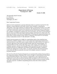
Carlsbad, New Mexico. As shown in Figure 1 and Table 1, the conterminous U.S.<br />
has many salt formations, including bedded and domal salt.<br />
For repository considerations and other uses, such as<br />
petroleum storage, salt formations are <strong>of</strong>ten categorized as<br />
“bedded” or “domal.” Bedded formations <strong>of</strong> salt (sodium<br />
chloride) are found in layers interspersed with materials<br />
such as anhydrite, shale, dolomite, and other salts such as<br />
potassium chloride. These formations are tabular and can<br />
range across enormous land areas (see Figure 1). Bedded<br />
salt formations are <strong>of</strong>ten between 200 to 600 meters thick,<br />
but in some cases they can have thicknesses <strong>of</strong> up to 1,000<br />
meters in the U.S. Domal formations (i.e., salt domes)<br />
form from salt beds when the density <strong>of</strong> the salt is less than<br />
that <strong>of</strong> surrounding sediment. Under such conditions, the<br />
salt has a tendency to move slowly upward toward the<br />
Advantages <strong>of</strong> salt for HLW disposal<br />
• <strong>Salt</strong> can be mined easily<br />
• <strong>Salt</strong> has a relatively high thermal<br />
conductivity<br />
• Wide geographic distribution (many<br />
potential sites)<br />
• <strong>Salt</strong> is plastic<br />
• <strong>Salt</strong> is essentially impermeable<br />
• Fractures in salt are self-sealing<br />
• <strong>Salt</strong> has been geologically stable for<br />
millions <strong>of</strong> years<br />
surface. As the buoyant salt moves upward, it deforms plastically into mushroomshaped<br />
diapirs and many other cylindrical and anticlinal shapes. The top <strong>of</strong> some<br />
domal salt can be near surface, while the root may extend to a great depth.<br />
Typically the diameter <strong>of</strong> a salt dome is on the order <strong>of</strong> 5 kilometers.<br />
5
Figure 1. <strong>Salt</strong> deposits in the United States (Johnson and Gonzales 1978).<br />
The five major regions <strong>of</strong> the U.S. where salt formations are found include (1) the<br />
Gulf Coast, (2) the Permian Basin, (3) the Michigan-Appalachian Region, (4) the<br />
Paradox Basin, and (5) the Williston Basin. Domal salts are found in the Gulf<br />
Coast region, and bedded salts are present in the remaining four major salt<br />
regions.<br />
Screening <strong>of</strong> the entire U.S. in the 1960s and 1970s identified the following large<br />
regions underlain by rock salt <strong>of</strong> sufficient depth and thickness to accommodate a<br />
repository:<br />
• <strong>Salt</strong> domes on the Gulf Coast. Using technical screening criteria, the<br />
Cypress Creek, Richton, and Vacherie Domes were identified as potentially<br />
acceptable sites.<br />
• Bedded salt in Utah. Based on technical screening criteria, Davis Canyon<br />
and Lavender Canyon were identified as potentially acceptable sites.<br />
6
Table 1. <strong>Salt</strong> and potash mines in the continental United States<br />
Name<br />
<strong>Salt</strong><br />
Type Location Company<br />
Depth<br />
(ft)<br />
• Bedded salt in western Texas and southeastern New Mexico. Permian<br />
bedded salt deposits in the Texas panhandle and western Oklahoma were<br />
found to be technically suited for waste disposal, and locations in northeastern<br />
Deaf Smith County and north-central Swisher County, Texas, were initially<br />
identified as potentially acceptable.<br />
In 1985, the Secretary <strong>of</strong> Energy nominated three salt formation sites from among<br />
the five sites taken forward for further consideration as repositories: Deaf Smith<br />
County, Texas, Davis Canyon, Utah, and Richton Dome on the Gulf Coast.<br />
Subsequently, in 1986, the Deaf Smith County site was selected to fully<br />
characterize. However, site characterization was not completed prior to the<br />
enactment <strong>of</strong> the 1987 amendments to the NWPA, which left only the Yucca<br />
Mountain site for full characterization.<br />
Mining experience in different salt terrains and at different depths demonstrates<br />
successful underground operations and extensive knowledge <strong>of</strong> isothermal<br />
conditions that would be considered in design <strong>of</strong> mined openings for disposal in<br />
salt. In the U.S., repository development would likely not involve conversion <strong>of</strong><br />
operating salt mines into repositories because <strong>of</strong> the specific design requirements<br />
desired for HLW disposal. Rather, a concept <strong>of</strong> operation would be developed<br />
Mined<br />
Height<br />
(ft)<br />
Cayuga Bedded Ithaca, NY Cargill 1,800 13<br />
Whiskey Island Bedded Cleveland, OH Cargill 1,850 28<br />
Lyons Bedded Lyons, KS Lyons <strong>Salt</strong> < 1,000 16<br />
Kanopolis Bedded Kanopolis, KS Independent <strong>Salt</strong> < 1,000 16<br />
Hutchinson Bedded Hutchinson, KS Vaults and Storage 1,000 16<br />
Detroit Bedded Detroit, MI Detroit <strong>Salt</strong> 1,800 18<br />
Fairport Bedded Fairport, OH Morton <strong>Salt</strong> 1,850 13<br />
Hampton’s Corner Bedded Geneseo, NY American Rock <strong>Salt</strong> 1,100 15<br />
East North Bedded Carlsbad, NM Intrepid Potash 700–2,000 6–7<br />
Nash Draw Bedded Carlsbad, NM Mosaic Potash 900–1,200 6–7<br />
Avery Island Domal Avery Island, LA Cargill<br />
25–100<br />
Weeks Island Domal Weeks Island, LA Morton <strong>Salt</strong> Vertically very deep 25–100<br />
Cote Blanche Domal Louisia, LA Compass Minerals with limited lateral<br />
extent<br />
25–100<br />
Hockley Domal Hockley, TX American <strong>Salt</strong> 25–100<br />
Grand Saline Domal Grand Saline, TX Morton <strong>Salt</strong> 25–100<br />
7
drawing from a wealth <strong>of</strong> mining experience and a new facility designed for the<br />
repository. Table 1 lists production salt and potash mines in the U.S. (not<br />
including solution mines), illustrating the regional availability <strong>of</strong> salt resources.<br />
1.3 History <strong>of</strong> <strong>Salt</strong> <strong>Disposal</strong> Research for <strong>Heat</strong>-<br />
<strong>Generating</strong> <strong>Nuclear</strong> <strong>Waste</strong><br />
In situ field tests to study the effects <strong>of</strong> HLW in bedded salt were initiated at an<br />
underground salt mine in Lyons, Kansas in 1965. By 1968, elevated-temperature<br />
HLW field experiments had begun at the Asse salt mine in Germany. In situ tests<br />
for brine migration resulting from heating were conducted at the Avery Island salt<br />
mine in Louisiana beginning in 1979. Soon after, an extensive suite <strong>of</strong> field<br />
thermal tests were initiated at the WIPP site near Carlsbad, New Mexico.<br />
Underground tests concentrated on heat dissipation and geomechanical response<br />
created by heat-generating elements placed in salt deposits. The following is a<br />
brief history <strong>of</strong> heated in situ testing in salt.<br />
1965–69. The first integrated field experiment for the disposal <strong>of</strong> HLW was<br />
performed by Oak Ridge National Laboratory in bedded salt near Lyons, Kansas.<br />
This test, named Project <strong>Salt</strong> Vault, used one set <strong>of</strong> irradiated fuel assemblies<br />
from the Engineering Test Reactor at Idaho Falls as a source <strong>of</strong> intense<br />
radioactivity, while electrical heaters were placed in boreholes in the floor to<br />
simulate decay heat generation <strong>of</strong> HLW. The tests simulated the heat flowing into<br />
the base <strong>of</strong> the pillar from a room filled with waste with the primary focus on rock<br />
mechanics <strong>of</strong> floor, ceiling, and pillar deformation.<br />
The tests also studied potential structural effects <strong>of</strong> radiation and found that there<br />
were none. Farbe centers (F centers) are <strong>of</strong>ten associated with radiation damage<br />
that creates blue and black salt crystals by virtue <strong>of</strong> a stoichiometric excess <strong>of</strong><br />
sodium. Sonnenfeld (1995) explains the several possible causes for colored salt,<br />
but no physical or mechanical behavior <strong>of</strong> importance to repository performance<br />
is attributed to radiation effects on salt.<br />
These pioneering tests with live UNF and simulated electrical heaters produced<br />
pillar temperatures <strong>of</strong> less than 50°C. Brine accumulation was observed after the<br />
electrical heaters were turned <strong>of</strong>f, which initiated the lingering issues <strong>of</strong> moisture<br />
behavior in such a setting. Possible brine inclusion migration and vapor transport<br />
phenomena were not completely resolved by these field experiments (Bradshaw<br />
and McClain 1971). These tests established that salt was an acceptable host rock<br />
for radioactive waste disposal, but local factors, both technical and political,<br />
resulted in abandonment in 1972 <strong>of</strong> an AEC proposal to construct a repository at<br />
the Lyons, Kansas, site.<br />
1968. Field experiments with electrical heaters were performed in the Asse salt<br />
mine to investigate the near-field consequences <strong>of</strong> emplaced HLW. These early<br />
experiments evaluated thermal-mechanical properties <strong>of</strong> the Stassfurt Halite.<br />
Later repository options were investigated, including vertical borehole disposal <strong>of</strong><br />
8
steel canisters and horizontal placement <strong>of</strong> steel casks surrounded with crushedsalt<br />
backfill. Emplacement <strong>of</strong> radioactive canisters was never realized; however, a<br />
placement system was successfully tested without radioactive material, and the<br />
system was approved by the responsible mining authority. In all, three large-scale<br />
“heater” experiments were performed in the Asse mine, which yielded important<br />
data for the validation <strong>of</strong> material and computer models needed to assess the<br />
coupled long-term behavior <strong>of</strong> rock salt and crushed salt backfill in a salt<br />
repository. The Asse experiments provided important lessons and guidance for<br />
future testing (Brewitz and Rothfuchs 2007, Kühn 1986).<br />
1979. Also in Germany, the Gorleben salt dome was investigated from 1979 until<br />
a moratorium beginning October 2000. In 1998, the German government<br />
expressed certain doubts with respect to the suitability <strong>of</strong> salt as a host rock in<br />
general and <strong>of</strong> the Gorleben site in particular. All exploration activities were<br />
halted by the end <strong>of</strong> 2000, and a moratorium was imposed for up to 10 years<br />
(Brewitz and Rothfuchs 2007). The moratorium ended in September 2010, so<br />
German repository scientists are poised to ramp up the salt repository<br />
investigations at Gorleben. Like the salt testing in the U.S., German research has<br />
provided a wealth <strong>of</strong> information on salt disposal research which is being and will<br />
be considered in future collaboration efforts (see Section 4.7).<br />
1979–82. Brine migration tests were performed by RESPEC for the Battelle<br />
Memorial Institute (BMI) Office <strong>of</strong> <strong>Nuclear</strong> <strong>Waste</strong> Isolation (ONWI) in the Avery<br />
Island salt mine in Louisiana. The migration <strong>of</strong> brine inclusions surrounding a<br />
heater borehole was studied on a macroscopic scale by investigating gross<br />
influences <strong>of</strong> thermal and stress conditions in situ. Field tests were augmented in<br />
the laboratory by microscopic observations <strong>of</strong> fluid inclusion migration within an<br />
imposed thermal gradient. The maximum temperature reached in the field test was<br />
51°C. Moisture collection during heater tests amounted to grams <strong>of</strong> water per day.<br />
When the heaters were shut <strong>of</strong>f, cooling caused changes in tangential stress,<br />
which led to microcracking, opening <strong>of</strong> grain boundaries, and moisture release. It<br />
was concluded that much <strong>of</strong> the moisture released was a result <strong>of</strong> this cooling<br />
process (Krause and Gnirk 1981).<br />
1983–85. A bilateral U.S.-German cooperative Brine Migration Test in the Asse<br />
salt mine investigated the simultaneous effects <strong>of</strong> heat and radiation on salt. This<br />
field experiment used cobalt-60 ( 60 Co) sources and heater arrays. The maximum<br />
temperature in the salt was 210°C, and the maximum temperature gradient was<br />
approximately 3°C/cm. The low moisture values measured suggest that the<br />
predominant migration mechanism in Asse salt is vapor migration. Similar to the<br />
Avery Island test results, a steep increase in brine release was noted because <strong>of</strong><br />
cool-down cracking caused when the heaters were shut <strong>of</strong>f (Rothfuchs et al.<br />
1988).<br />
1984–1993. Three separate simulated HLW heater tests were performed at<br />
WIPP: (1) 18 W/m 2 DOE high-level waste (DHLW) mockup, (2) DHLW overtest,<br />
and (3) the <strong>Heat</strong>ed Axisymmetric Pillar test. The 18 W/m 2 DHLW mockup<br />
9
and DHLW over-test were designed to identify how the host rock and the disposal<br />
room respond to the excavation itself and then to the heat generated from waste<br />
placed in vertical holes in the drift floor. These tests imparted a relatively modest<br />
thermal load in a vertical borehole arrangement and did not use crushed-salt<br />
backfill or explore reconsolidation <strong>of</strong> salt. They primarily focused on the<br />
mechanical response <strong>of</strong> the salt under modest heat load. The results can be used,<br />
for example, to validate the next-generation high-performance codes over a<br />
portion <strong>of</strong> the multiphysics functionalities. The <strong>Heat</strong>ed Axisymmetric Pillar test<br />
involved an isolated, cylindrically shaped salt pillar and provides an excellent<br />
opportunity to calibrate scale effects from the laboratory to the field, as well as a<br />
convenient configuration for computer model validation (Matalucci 1987).<br />
1985–1990. A set <strong>of</strong> moisture transport and release tests were part <strong>of</strong> the<br />
borehole plugging and sealing test series at WIPP and were designed to measure<br />
moisture release associated with heated boreholes and to evaluate transport<br />
mechanisms. Each borehole contained a nitrogen flow and a water vapor<br />
collection and measurement system. Water vapor flowing in the nitrogen was<br />
collected and weighed (Nowak and McTigue 1987). These data characterizing<br />
brine movement and accumulation were interpreted in terms <strong>of</strong> a model for flow<br />
in a saturated porous medium. Comparisons between model calculations and brine<br />
inflow rates showed order-<strong>of</strong>-magnitude agreement for permeability in accord<br />
with independent in situ determinations <strong>of</strong> permeability in the salt. Expected<br />
accumulations <strong>of</strong> brine in typical WIPP waste disposal rooms were calculated by<br />
numerical methods using a mathematical description for the brine inflow model.<br />
Brine accumulation in a disposal room was calculated to be in the range <strong>of</strong> 4 m 3 to<br />
43 m 3 in 100 years. The maximum expected accumulation, 43 m 3 , is 1.2% <strong>of</strong> the<br />
initial room volume, about the same as the quantity <strong>of</strong> brine in the salt that was<br />
removed by mining the room (Nowak, McTigue, and Beraun 1988).<br />
1986–1991. An in situ test <strong>of</strong> simulated HLW glass and other waste package<br />
components was conducted at WIPP beginning in 1986 in a program known as<br />
the Materials Interface Interactions Test (MIIT). The MIIT involved<br />
approximately 1,900 samples in 50 test boreholes, with specimens that included<br />
16 variations <strong>of</strong> simulated HLW glass, 11 potential canister metals, rock salt, and<br />
two brine solutions (Wicks and Molecke 1988). The MIIT included a 5-year study<br />
<strong>of</strong> the burial <strong>of</strong> simulated waste glasses and the resulting long-term waste-glass<br />
leaching behavior. Brine analyses were performed on samples from selected<br />
boreholes containing simulated waste-glass specimens, resulting in release rates<br />
<strong>of</strong> less than one part in 100,000 for all elements investigated (Wicks 2001).<br />
1.4 Analogues for <strong>Salt</strong> <strong>Disposal</strong><br />
As this report acknowledges, some key issues pertaining to HLW disposal in salt<br />
need attention if a salt disposal option is selected. These remaining issues should<br />
not be misconstrued to imply the scientific basis for salt disposal is weak. It is<br />
not. <strong>Salt</strong> disposal remains a very favorable option for the U.S. The most likely<br />
future for HLW salt disposal includes permanent, dry encapsulation.<br />
10
Considerable qualitative support for this strong impression derives from pertinent<br />
analogues.<br />
Many anthropogenic and geologic analogues provide insight into permanent<br />
nuclear waste disposal in salt. Anthropogenic analogues derive from over 7,000<br />
years <strong>of</strong> salt excavation by mankind and wide use <strong>of</strong> salt formations, including<br />
storage <strong>of</strong> fluid hydrocarbons. Fifty years ago the unique sealing capability <strong>of</strong> salt<br />
was dramatically demonstrated by the most severe test possible: containment <strong>of</strong><br />
nuclear detonations in salt horizons. In addition to anthropogenic evidence from<br />
mining experience and nuclear detonations, nature itself showcases the<br />
encapsulating ability <strong>of</strong> salt formations penetrated by high-temperature magmatic<br />
dikes. The analogues summarized here provide qualitative evidence that salt<br />
formations have the capacity to contain a wide variety <strong>of</strong> severe conditions<br />
permanently.<br />
Sealing a nuclear waste repository and waste corrosion are considered two<br />
primary issues with salt disposal. Anthropogenic evidence associated with vast<br />
and pertinent mining experience provides important qualitative assessments <strong>of</strong><br />
preserved artifacts. The Hallstatt area in Austria supported prehistoric salt<br />
mining. Archeological re-excavation has recovered organic material such as<br />
leather, wood, clothing and even an unfortunate Celtic miner preserved in the salt<br />
for 3,000 years. More recent analogues spanning 50 or 100 years <strong>of</strong> mining<br />
experience <strong>of</strong>fer convincing evidence <strong>of</strong> structural, mechanical, and hydrological<br />
behavior <strong>of</strong> the underground salt environment. The salt and potash mining<br />
industry has placed functional seals in underground workings, backfilled, and<br />
reconsolidated crushed salt in active mining operations. Within the potash basin in<br />
southeastern New Mexico mining operations, machinery which is not brought<br />
back to surface suffers almost no corrosion after more than 50 years.<br />
The most dramatic man-made analogues—considered beyond-worst-case<br />
analogues—are nuclear detonations in salt (Rempe 1998). The USA has<br />
detonated three nuclear devices in salt: one at the Gnome Site near WIPP and two<br />
at the Salmon Site at Tatum Dome in Mississippi. The 3.1 kiloton Gnome shot,<br />
which unintentionally breached drift seals and sent radioactive steam up the shaft,<br />
was cleaned up by dumping the surface material down the shaft and thereafter<br />
recommended for public release (Gardner and Sigalove 1970). The Gnome shot<br />
was situated near the top <strong>of</strong> the Salado Formation, roughly half as deep as the<br />
WIPP repository. No migration has been detected outside the experiment’s<br />
boundary for half a century. The Tatum tests involved two sequential devices; the<br />
second was detonated in the cavity created by the first. By virtue <strong>of</strong> monitoring<br />
results, the radioisotopes were determined to be confined to the test cavity, i.e.,<br />
the test cavity was determined not to be leaking radioactivity (DOE 1999). The<br />
Tatum shots were executed at a depth <strong>of</strong> 2,700 feet. <strong>Salt</strong> formations have been<br />
shown to seal and confine nuclear detonations.<br />
Geologic analogues also supply strong evidence <strong>of</strong> the confining nature <strong>of</strong> salt<br />
formations. Examples <strong>of</strong> natural geologic analogues include salt formations in<br />
11
New Mexico and Germany that have been intersected by magmatic dikes (Loehr<br />
1979; Knipping 1989; Knipping and Herrmann 1985; Steinmann and Stille 2004).<br />
Despite the severe nature <strong>of</strong> such magmatic intrusions, there are only very thin<br />
alteration zones at the contact between the high-temperature igneous intrusion and<br />
the salt. No evidence <strong>of</strong> significant fluid (inclusion) migration toward the heat<br />
source has been reported from field observations.<br />
Analogues involving massively disruptive events within a salt formation create<br />
accessible evidence <strong>of</strong> salt containment over very large spatial domains and<br />
lengthened time periods. As such, these analogues are tantamount to qualitative<br />
performance assessment arguments for complete containment <strong>of</strong> nuclear waste<br />
disposal in salt. Obviously, there are no engineered barriers involved with<br />
entombment and isolation demonstrated by analogues. Properties <strong>of</strong> salt itself<br />
allow the geological formation to absorb the intrusion and naturally seal and<br />
encapsulate it.<br />
It is the opinion <strong>of</strong> the technical repository community that the U.S. could<br />
construct suitable permanent repositories in a variety <strong>of</strong> geological disposal media<br />
including salt (Hansen, Hardin, and Orrell 2011). Table 2 provides a qualitative<br />
comparison <strong>of</strong> salt to other geologic media. Because <strong>of</strong> the long and visible salt<br />
history, these formations have exhibited many characteristics favorable to<br />
permanent isolation. Many <strong>of</strong> these parameters for salt will reviewed in<br />
Section 2.<br />
12
Table 2. Qualitative comparison <strong>of</strong> geologic media as HLW repository host<br />
Thermal<br />
Conductivity<br />
<strong>Salt</strong> Shale Granite Deep Boreholes<br />
Permeability Practically impermeable Very low to low<br />
High Low Medium Medium<br />
Very low (unfractured)<br />
to permeable (fractured)<br />
Strength Medium Low to medium High High<br />
Very low<br />
Deformation<br />
behavior<br />
Stability <strong>of</strong> cavities<br />
Visco-plastic (creep) Plastic to brittle Brittle Brittle<br />
Self-supporting on the<br />
scale <strong>of</strong> decades<br />
Artificial reinforcement<br />
required<br />
High (unfractured)<br />
to low (highly fractured)<br />
Medium at great depth<br />
In situ stress Isotropic Anisotropic Anisotropic Anisotropic<br />
Dissolution<br />
behavior<br />
High Very low Very low Very low<br />
Sorption behavior Very low Very high Medium to high Medium to high<br />
Chemistry Reducing Reducing Reducing Reducing<br />
<strong>Heat</strong> resistance High Low High High<br />
Mining experience High Low High Low<br />
Available geology Wide Wide Medium Wide<br />
Geologic stability High High High High<br />
Engineered barriers Minimal Minimal Needed Minimal<br />
Favorable quality Average or variable quality Unfavorable property<br />
13
2 TECHNICAL BASIS AND<br />
CHARACTERIZATION<br />
Underlying a decision to proceed with disposal in a particular geologic medium is<br />
the technical basis pertaining to that medium, the waste inventory and the design<br />
concept. In this particular instance, the primary emphasis is on the salt medium. A<br />
specific repository design is not suggested although experience and lessons<br />
learned are reviewed. A shaft seal system for a salt repository has been designed,<br />
reviewed, and accepted, so that successful body <strong>of</strong> work is included in this<br />
section. <strong>Salt</strong> mining experience, salt repository operations, and the scientific<br />
investigations supporting them provide a considerable technical basis for<br />
elucidation <strong>of</strong> the thermal-hydrological-mechanical conditions for the host rock.<br />
Perspectives on the geochemical behavior <strong>of</strong> salt are <strong>of</strong>fered.<br />
2.1 <strong>Nuclear</strong> <strong>Waste</strong> Characteristics<br />
In the U.S., waste designations are not only linked to the level <strong>of</strong> radioactivity in<br />
the waste, but also, in some cases, to the source <strong>of</strong> the waste. In other countries,<br />
waste designations vary from those in the U.S. It is not the intent <strong>of</strong> this report to<br />
develop a new waste designation nor is it the intent to specify which wastes<br />
specifically can be disposed in salt. It is clear, however, from the technical basis<br />
established in this report that many forms <strong>of</strong> thermally-hot nuclear waste could be<br />
permanently and safely disposed in salt. The waste forms to be disposed could<br />
include HLW and/or UNF. In 2008, the DOE estimated that 109,300 metric tons<br />
heavy metal (MTHM) <strong>of</strong> HLW and UNF in the U.S. will ultimately need to be<br />
stored (DOE 2008b). This inventory consists <strong>of</strong> 70,000 MTHM that is included in<br />
the Yucca Mountain license application, with the remainder from future<br />
production.<br />
The inventory includes commercial spent nuclear fuel (CSNF), DOE spent<br />
nuclear fuel (DSNF), and high-level waste glass (HLWG). The inventory consists<br />
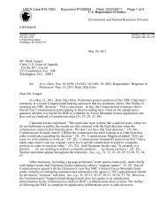
<strong>of</strong> actinide elements in several radionuclide decay chains (Figure 2) along with a<br />
number <strong>of</strong> fission products. By weight, CSNF from once-through light-water<br />
reactors is about 97% 238 U, with contributions <strong>of</strong> 0.3–0.8% from 235 U, 236 U, 239 Pu,<br />
and 240 Pu. All other radionuclides contribute less than 0.1%. The importance <strong>of</strong><br />
the various radionuclides changes with time due to the effects <strong>of</strong> decay and<br />
ingrowth.<br />
HLW could include multiple waste forms: uranium dioxide (UO 2 ) pellets,<br />
borosilicate glass, ceramics, or metal. UO 2 pellets would result from direct<br />
disposal <strong>of</strong> UNF. Borosilicate glass and/or ceramics would result from disposal<br />
<strong>of</strong> HLW, and metals would result from direct disposal <strong>of</strong> activated metals. The<br />
waste form after long-term storage prior to disposal will not differ from waste<br />
disposed promptly after generation. Thus, the inventory consists <strong>of</strong> chemical<br />
elements from several sources as shown in Table 3.<br />
15
Source: Sandia National Laboratories 2008, Figure 6.3.7-4.<br />
a<br />
A series <strong>of</strong> short-lived daughters between 226 Ra and 210 Pb are not shown. Also, 210 Pb is<br />
not used to calculate dose directly, but its biosphere dose conversion factor is included<br />
with that <strong>of</strong> 226 Ra in performance assessments.<br />
b<br />
The value listed under each radionuclide is the approximate decay half-life for the<br />
radionuclide.<br />
Figure 2. Decay chains <strong>of</strong> the actinide elements for HLW isotopes<br />
16
<strong>Heat</strong> generation is one <strong>of</strong> the primary<br />
characteristics <strong>of</strong> HLW. <strong>Heat</strong> is generated<br />
because <strong>of</strong> the radionuclides contained in<br />
the waste. For UNF, ten years after<br />
removal from a reactor, approximately<br />
77% <strong>of</strong> the thermal power originates from<br />
the decay <strong>of</strong> 137 Cs and 90 Sr and their<br />
daughters, with almost all <strong>of</strong> the remaining<br />
heat from actinide decay. In the short term,<br />
such as cooling times less than 50 years,<br />
the decay <strong>of</strong> 90 Sr and 137 Cs continue to<br />
produce the majority <strong>of</strong> the overall heat<br />
from UNF, and maximum heat output<br />
values are experienced during this time<br />
frame (Michaels 1996).<br />
Table 3. Chemical elements to be considered in<br />
a HLW chemical model<br />
Element Sources<br />
Al Host rocks, waste form<br />
Am Actinide element in waste<br />
B <strong>Waste</strong> form<br />
Daughter <strong>of</strong> 137 Cs, which is fission product<br />
Ba in waste form<br />
Cm Actinide element in waste<br />
Co Canisters<br />
Cs Fission product in waste form<br />
Fe Canisters and backfill materials<br />
I Fission product in waste form<br />
Permanganate used for removal <strong>of</strong> Sr and<br />
Mn actinides prior to vitrification<br />
Ni Activation product in waste form<br />
Over periods longer than 100 years, after<br />
heat generation from the 90 Sr and 137 Cs has<br />
tapered <strong>of</strong>f, it is the alpha decay <strong>of</strong> various<br />
actinides—principally Pu and Am—that<br />
dominates the total heat output <strong>of</strong> UNF.<br />
The actinides account for about 80% <strong>of</strong> the<br />
Pb<br />
Pd<br />
Pu<br />
Se<br />
Si<br />
Canisters<br />
Fission product in waste form<br />
Actinide element in waste<br />
Fission product in waste form<br />
<strong>Waste</strong> form, backfill materials, and host<br />
rocks<br />
cumulative heat that is generated over the Sn Fission product in waste form<br />
first l,000 years. For time frames beyond Sr Fission product in waste form<br />
1,000 years, actinides contribute about<br />
Daughter <strong>of</strong> 125 Sb, which is fission product<br />
Te in waste form<br />
99% <strong>of</strong> the additional heat generated in a<br />
Monosodium titanate used for removal <strong>of</strong><br />
repository. In the context <strong>of</strong> overall bulk<br />
Ti Sr and actinides prior to vitrification<br />
temperatures <strong>of</strong> large volumes <strong>of</strong> the<br />
Th Actinide element in waste<br />
repository site, decay <strong>of</strong> actinides with<br />
U Actinide element in waste<br />
intermediate half-lives dominates longterm<br />
heat production, not the decay <strong>of</strong><br />
Sr, which is a fission product<br />
Daughter <strong>of</strong><br />
fission products such as 90 Sr and 137 Y in waste form<br />
Cs Zr Fission product in waste form<br />
(Michaels 1996). However, as explained<br />
in the following sections, the relatively rapid response <strong>of</strong> salt and the early<br />
evolution <strong>of</strong> the disposal room dominate the long-term performance assessment.<br />
The nuclear waste material to be permanently disposed has been well<br />
characterized and would be further evaluated if salt media are selected for<br />
disposal investigations. The concept <strong>of</strong> operations for salt disposal can be readily<br />
engineered to accommodate a broad spectrum <strong>of</strong> waste volumes, types, and heat<br />
generation capacities. <strong>Salt</strong> repository design, as described in Section 2.2, can<br />
include many systems because design approaches for disposal in salt are not<br />
predicated on any particular waste form or package. If the nuclear waste can be<br />
safely transported to the shaft station, it can be disposed in salt with no further<br />
packaging or treatment.<br />
17
2.2 <strong>Salt</strong> Repository Design<br />
A mine layout for HLW disposal in salt can be quite flexible. For example, the<br />
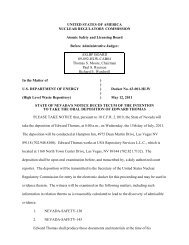
well-known concept <strong>of</strong> operations utilized at WIPP includes stacking <strong>of</strong> contacthandled<br />
(CH) waste on the floor and horizontal disposal <strong>of</strong> remotely handled<br />
(RH) waste in pillars as shown in the photograph in Figure 3. Internationally,<br />
Germany has taken a leading role in underground waste disposal in rock salt<br />
formations, as recounted in Section 1.3. Since 1967, a former salt mine (Asse) in<br />
north-central Germany fulfilled the technical criteria <strong>of</strong> a radioactive waste<br />
repository. The Asse mine was also used as a research facility for a number <strong>of</strong><br />
years. The feasibility <strong>of</strong> both borehole and drift disposal concepts has been<br />
demonstrated by about 30 years <strong>of</strong> testing in the Asse mine (Brewitz and<br />
Rothfuchs 2007). At the Asse mine, large-scale disposal operations included<br />
stacking drums, covering them with salt, and then stacking more drums on top.<br />
The German reference disposal concept for HLW is horizontal placement <strong>of</strong><br />
POLLUX casks (Bechthold et al. 2004); however, recent developments have<br />
outlined a new disposal technology for disposal in vertical boreholes in the salt<br />
room floor (Filbert et al. 2010).<br />
Figure 3. <strong>Disposal</strong> operations for TRU waste at the WIPP<br />
Since 1978, the former German Democratic Republic disposed low- and<br />
intermediate-level wastes in the Morsleben potash and salt mine (also known as<br />
ERAM). Morsleben employed several techniques including in situ solidification<br />
<strong>of</strong> liquid waste, stacking, and dumping <strong>of</strong> solid wastes. Solidification <strong>of</strong> the liquid<br />
used brown coal filter ash as a binding agent. <strong>Disposal</strong> ceased altogether in 1998,<br />
18
and designs for closure have been developed since operations were terminated.<br />
For two decades, the Gorleben salt dome in north-central Germany had been<br />
investigated for its suitability to host all categories <strong>of</strong> radioactive waste, including<br />
heat-generating HLW. Although no country has a repository for HLW in salt, the<br />
experiments and disposal demonstration attest to the flexibility <strong>of</strong> the concept <strong>of</strong><br />
disposal operations.<br />
2.2.1 Concept <strong>of</strong> <strong>Disposal</strong> for HLW in <strong>Salt</strong><br />
A recent conceptual salt repository study called the generic salt repository for<br />
HLW advanced a new disposal concept based on lessons learned from the WIPP,<br />
Asse, and Morsleben (Washington Savannah River Company et al. 2008). The<br />
generic study involved a conceptual mining layout that was developed for a highthermal-load<br />
salt repository based on experience and mining observations. First a<br />
rough layout was proposed based on waste handling, convenience, expectation <strong>of</strong><br />
standup time, and other criteria. A thermal calculation was run to evaluate<br />
temperature distribution, especially maximum temperatures. The mining layout<br />
was adjusted to accommodate a selected design basis throughput and balance the<br />
thermal load in the underground. This scoping study for a generic salt repository<br />
was not a design optimization study, and dimensions and disposal options were<br />
based on design guidance gained from practical experience.<br />
Contributors to the generic salt repository study developed a possible repository<br />
layout and also generated some basic operational and structural conclusions,<br />
including (1) use rubber-tire disposal vehicles, (2) avoid use <strong>of</strong> predrilled holes,<br />
(3) do not use shielded containers for disposal, and (4) use narrow room widths to<br />
improve mining efficiency and structural stability.<br />
The study concluded that the alternative <strong>of</strong> using rail for moving waste to the<br />
disposal zone would be difficult operationally. Rail systems would need to be<br />
constructed and then remain readily functional in a deforming salt medium. A<br />
rubber-tire fork lift machine can readily haul payloads to the disposal zone.<br />
The disposal system should be made simple without sacrificing safety. WIPP<br />
disposal operations experience led to the conclusion that the concept <strong>of</strong> operations<br />
should not involve placing waste canisters in predrilled boreholes. Drilling such<br />
holes adds a logistical step to the disposal process, while emplacing waste<br />
packages into such holes is time consuming because <strong>of</strong> alignment requirements.<br />
Predrilled horizontal disposal holes require wide room span, and vertical holes in<br />
the floor would have to accommodate the drilling rig and emplacement<br />
equipment. The combination <strong>of</strong> rubber-tired equipment and emplacement without<br />
boreholes led to the selection <strong>of</strong> a simple disposal scheme that placed the canisters<br />
at the end <strong>of</strong> a mined alcove. The trade-<strong>of</strong>f between drilling holes and mining<br />
alcoves for disposal favored the alcove disposal concept.<br />
The alcove disposal concept can also accommodate disposal <strong>of</strong> unshielded<br />
containers. The waste could be transported in a shielded container but disposed<br />
unshielded. The alcove disposal concept requires that mine-run crushed salt be<br />
19
placed over the waste canisters for radiological shielding. The operation <strong>of</strong><br />
placing the crushed salt over the waste would involve remote controlled loadhaul-dump<br />
machinery similar to that used in salt mining today.<br />
Width <strong>of</strong> the main disposal drifts and alcoves was selected for mining<br />
convenience. The typical continuous miner used at WIPP today cuts nominally<br />
11-foot swaths. Therefore, the mining system would involve essentially one-pass<br />
mining. The stand-up time under ambient conditions associated with roughly 11-<br />
foot dimensions was not calculated, but based on WIPP experience structural<br />
stability would endure for many years without bolting.<br />
The width-to-height ratio, extraction ratio, depth, and geometry govern<br />
underground standup time. Pillars take up the load when excavations are created.<br />
The width-to-height ratio <strong>of</strong> the pillar controls the pillar strength. Shorter pillars<br />
are stronger than taller pillars because <strong>of</strong> the confining effects experienced at the<br />
ends. For this generic salt repository layout, a nonspecific room height from seven<br />
to ten feet could be readily mined with current equipment.<br />
Other recommendations included avoiding sequential co-disposal <strong>of</strong> remotely<br />
handled waste and contact-handled waste. The disposal sequence should proceed<br />
from the most distal excavations inward. This avoids having to transport past<br />
filled disposal rooms and promotes modular panel isolation. The concept <strong>of</strong><br />
disposal in salt can be flexible. <strong>Heat</strong> generation, though important, can be readily<br />
accommodated by design.<br />
2.3 Seals<br />
This section describes a shaft sealing system design for the WIPP, which has been<br />
reviewed and certified by the EPA regulator. The system is designed to limit entry<br />
<strong>of</strong> water and release <strong>of</strong> contaminants through the existing shafts after<br />
decommissioning. The design approach applied redundancy to functional<br />
elements and specifies multiple, common, low-permeability materials to reduce<br />
uncertainty in performance. The system comprises 13 elements that completely<br />
fill the shafts with engineered materials possessing high density and low<br />
permeability. Laboratory and field measurements <strong>of</strong> component properties and<br />
performance provided the basis for the design and related evaluations.<br />
Hydrologic, mechanical, thermal, and physical features <strong>of</strong> the system were<br />
evaluated in a series <strong>of</strong> calculations. These evaluations indicated that the design<br />
effectively limits transport <strong>of</strong> fluids within the shafts, thereby limiting transport <strong>of</strong><br />
hazardous material to regulatory boundaries. Additionally, the use or adaptation<br />
<strong>of</strong> existing technologies for placement <strong>of</strong> the seal components combined with the<br />
use <strong>of</strong> available, common materials ensure that the design can be constructed<br />
(Hansen and Knowles 2000).<br />
The design <strong>of</strong> the seal system for a HLW salt repository would benefit from<br />
design and performance calculations on seal systems developed for the WIPP,<br />
which were subject to extensive technical peer review and comprise published<br />
20
portions <strong>of</strong> the Compliance Certification Application to the EPA. The<br />
fundamental design principle for seal systems in a nuclear waste repository is to<br />
limit water flow from disposal cells to access shafts to zero or specified<br />
acceptable levels. Extensive design, analysis, and testing for shaft seals were<br />
performed for the WIPP repository, which provides the basis for performance<br />
expectations.<br />
An acceptable seal system can be designed and constructed using existing<br />
technology, and the seal system can readily meet requirements associated with<br />
repository system performance. These goals would be met by using a set <strong>of</strong><br />
guidelines that incorporates seal performance issues, and with a commitment that<br />
the seal system design would implement accepted engineering principles and<br />
practices. These guidelines were formalized as design guidance for the shaft seal<br />
system:<br />
• Limit waste constituents reaching regulatory boundaries<br />
• Restrict formation water flow through the seal system<br />
• Use materials possessing mechanical and chemical compatibility<br />
• Protect against structural failure <strong>of</strong> system components<br />
• Limit subsidence and prevent accidental entry<br />
• Utilize available construction methods and materials.<br />
The shaft seal system would limit entry <strong>of</strong> formation water into the repository and<br />
restrict the release <strong>of</strong> fluids that might carry contaminants. Seals are designed to<br />
limit fluid transport through the opening itself, along the interface between the<br />
seal material and the host rock, and within the disturbed rock surrounding the<br />
opening. The shaft seal system design for WIPP was completed under a quality<br />
assurance program that meets EPA regulations, including review by independent,<br />
qualified experts. Technical reviewers examined the complete design including<br />
conceptual, mathematical, and numerical models and computer codes. The design<br />
reduces the impact <strong>of</strong> uncertainty associated with any particular element by using<br />
multiple sealing system components and by using components constructed from<br />
different materials.<br />
The sequence <strong>of</strong> repository operations would include site construction, waste<br />
emplacement, seal installation, repository closure, and abandonment. However,<br />
owing to the potentially long time periods involved, considerations such as loss <strong>of</strong><br />
institutional control enter into the design and concept <strong>of</strong> operations. Events such<br />
as war or natural disaster may lead to premature repository abandonment. These<br />
hypothetical futures have been considered by many, if not all, repository<br />
programs. The impact <strong>of</strong> these potential situations is minimized by sealing<br />
emplacement drifts in modular compartments in due course <strong>of</strong> disposal<br />
operations. Therefore, in addition to the shaft seal system, a nuclear waste<br />
repository design would likely include a modular concept whereby the whole<br />
repository comprises sections or modules that are sequentially partitioned and<br />
isolated with horizontal panel closures (i.e., seals). The repository modules would<br />
be separated from one another by sufficient distance that thermal, hydrologic, and<br />
21
other possible modes <strong>of</strong> interference are inconsequential. After the repository is<br />
filled with emplaced waste and horizontal panels are closed, seals would be<br />
installed in the access shafts.<br />
Similar to the WIPP shaft seal design, from the disposal horizon upward, the shaft<br />
seal system would include the following components:<br />
• Shaft Station Monolith—The base <strong>of</strong> the shaft will be sealed with saltsaturated,<br />
Portland cement-based concrete. It will be placed by tremie line<br />
techniques against nonremovable (committed material) forms, which could be<br />
fabricated from concrete block or other abutments.<br />
• Clay Column—A sodium bentonite compacted clay component is placed on<br />
top <strong>of</strong> the mass <strong>of</strong> concrete. Alternative construction methods including block<br />
placement and dynamic compaction are viable. Clay columns effectively limit<br />
formation water movement from the time they are placed. The stiffness or<br />
swelling pressure associated with the clay column is sufficient to promote<br />
healing <strong>of</strong> fractures in the surrounding rock near the bottom <strong>of</strong> the shafts, thus<br />
effectively removing the proximal damage zone as a potential pathway.<br />
• <strong>Salt</strong> Column—A crushed salt element for the shaft seal system has been<br />
thoroughly evaluated for salt application. The performance has been<br />
established from the microstructural scale to the full construction scale. Very<br />
low permeability is attained by the crushed salt in laboratory time, which is an<br />
excellent basis for concluding the crushed salt element will become<br />
impermeable in a matter <strong>of</strong> decades.<br />
• Asphalt Column—Asphalt is a widely used construction material with<br />
properties considered desirable for sealing applications. Asphalt is readily<br />
adhesive, highly waterpro<strong>of</strong>, and durable. Furthermore, it is a plastic<br />
substance that provides controlled flexibility to mixtures <strong>of</strong> mineral<br />
aggregates with which it is usually combined. It is highly resistant to most<br />
acids, salts, and alkalis. A number <strong>of</strong> asphalts and asphalt mixes are available<br />
that cover a wide range <strong>of</strong> viscoelastic properties and which can be tailored to<br />
design requirements.<br />
• Earthen Fill—The upper shaft is filled with locally available earthen fill. Most<br />
<strong>of</strong> the fill is dynamically compacted (e.g., by the method used to construct the<br />
compacted clay column) to a density approximating the surrounding<br />
lithologies. The uppermost earthen fill is compacted with a sheep-foot roller<br />
or vibratory plate compactor.<br />
As described among the analogues summarized in Section 1.4, three atomic<br />
explosions were detonated in salt. No special seal provisions were made in any<br />
case. In the fifty years since the nuclear tests in salt, there is no detectable<br />
release. For sealing a salt HLW nuclear waste repository, the engineering and<br />
material specifications developed for the WIPP can be translated with minor<br />
22
modifications <strong>of</strong> functional and operational requirements. The seal material<br />
specifications, construction methods, rock mechanical analyses, and fluid flow<br />
evaluations already developed and approved remain applicable. This design<br />
concept is not the only possible combination <strong>of</strong> materials and construction<br />
strategies that would adequately limit fluid flow within the shafts; however, its<br />
high performance with common materials and technologies and functional<br />
redundancy proved to the regulators and stakeholders that the salt repository will<br />
be totally isolated after closure.<br />
A major intrinsic advantage <strong>of</strong> a salt repository is the lack <strong>of</strong> groundwater to seal<br />
against. Even though regional aquifers may be proximal to the host unit, the shaft<br />
seal system would be designed to perform in contact with groundwater. If water<br />
flow occurs within the repository openings or in the disturbed-rock zone (DRZ),<br />
the chemistry <strong>of</strong> water or brine could impact engineered materials. However, the<br />
geochemical setting will have little influence on the concrete, asphalt, and clay<br />
shaft seal materials. Each material is durable with minimal potential for<br />
degradation or alteration. Microbial degradation, material interactions, and<br />
mineral transformations are <strong>of</strong>ten incompletely understood, and therefore<br />
continue to be the focus <strong>of</strong> ongoing research. Degradation <strong>of</strong> concrete is possible,<br />
but unlikely as only small volumes <strong>of</strong> groundwater will ever reach the concrete.<br />
Moreover, in a closed system, such as the hydrologic setting for these shafts,<br />
cement phase transformations would decrease the permeability <strong>of</strong> concrete seal<br />
elements.<br />
Asphalt used as a seal component deep in the shaft will occupy a benign<br />
environment, devoid <strong>of</strong> ultraviolet light or an oxidizing atmosphere that could<br />
degrade the sealing capability <strong>of</strong> asphalt. Assurance against possible microbial<br />
degradation in asphalt elements used in a salt shaft seal design could be provided<br />
with addition <strong>of</strong> lime. For these reasons, it is believed that asphalt components<br />
can retain their design characteristics for an indefinitely long period.<br />
Natural bentonite is a widely used, geologically stable sealing material. Three<br />
internal mechanisms, illitization, silicification, and ion exchange, could affect<br />
sealing properties <strong>of</strong> bentonite. Illitization and silicification are thermally driven<br />
processes unlikely to occur in the salt environment over the period <strong>of</strong> regulatory<br />
concern. Significant degradation due to ion exchange would require extensive<br />
fluid transport <strong>of</strong> calcium through the bentonite and sodium away from the seal,<br />
which is unlikely. Wyoming bentonite—the specified material for the seal<br />
system—has existed unaltered for well over a million years in its natural<br />
environment.<br />
The shaft seal system described above could be constructed using <strong>of</strong>f-the-shelf<br />
technology. A more comprehensive treatment and specific analyses are available<br />
in Hansen and Knowles (2000). The seal design system described by Hansen and<br />
Knowles could be readily modified, perhaps simplified, and construction<br />
alternatives may be implemented during repository development. This section<br />
23
provides frame <strong>of</strong> reference for shaft seal design and analysis for a potential salt<br />
repository for HLW in the U.S.<br />
2.4 Thermal-Hydrologic-Mechanical Conditions in the<br />
Host Rock<br />
<strong>Salt</strong> formations have naturally low permeability and self-sealing characteristics<br />
favorable to waste isolation. This section describes observations and experience in<br />
salt mines, in situ testing, laboratory testing, salt repository science, and<br />
geomechanics research nationally and internationally to establish a range <strong>of</strong> salt<br />
characteristics pertinent to a salt repository. This wealth <strong>of</strong> experience provides a<br />
firm foundation for advanced salt repository sciences. It also provides the basis<br />
for defining applied research needs to further the science in areas that are specific<br />
to the thermal aspects <strong>of</strong> HLW disposal. These considerations lead to approaches<br />
for representing thermal, mechanical, hydrological, and geochemical conditions<br />
possible in a salt repository for HLW.<br />
2.4.1 Excavation/Construction Effects<br />
Excavation geomechanics are a starting point for demonstrating the technical<br />
viability <strong>of</strong> nuclear waste disposal. Design and operation <strong>of</strong> the facility and the<br />
assurance <strong>of</strong> long-term isolation rely on knowledge <strong>of</strong> the geomechanical<br />
response. This section summarizes current treatment <strong>of</strong> the damaged rock around<br />
excavated openings as related to disposal operations, isolation <strong>of</strong> wastes, and<br />
performance assessment. Geomechanical creep in salt has long been recognized<br />
as favorable for nuclear waste isolation. Attributes <strong>of</strong> plasticity and<br />
impermeability provide assurance that once emplaced within salt disposal rooms,<br />
the radioactive wastes will be isolated from the accessible environment essentially<br />
forever.<br />
Much <strong>of</strong> the salt geomechanics knowledge in the U.S. derives from site<br />
characterization for the WIPP facility, situated in the Salado Formation, a<br />
Permian bedded-salt formation in southeastern New Mexico. Background<br />
information can be accessed from the WIPP website<br />
(http://www.wipp.energy.gov). The WIPP is a disposal facility for defensegenerated<br />
TRU waste from across the nuclear complex. First receipt <strong>of</strong> waste<br />
occurred in March 1999, following the original certification by the EPA that the<br />
facility complies with the regulations. Compliance was recertified after five years<br />
<strong>of</strong> operations, and recently EPA issued its second recertification.<br />
2.4.1.1 Elements <strong>of</strong> the Disturbed Rock Zone (DRZ)<br />
The DRZ constitutes an important geomechanical element <strong>of</strong> salt behavior and is<br />
explicitly included in seal design and performance assessment. The PA<br />
philosophy incorporates features, events, and processes (FEPs) into conceptual<br />
and numerical models used to predict probable future states <strong>of</strong> the repository over<br />
the regulated period. This section reviews the DRZ information base and<br />
24
experience because the DRZ is among the prominent FEPs associated with waste<br />
disposal in salt.<br />
<strong>Salt</strong>, being a plastic medium at repository depth, exhibits a virgin lithostatic<br />
(isotropic) state <strong>of</strong> stress. Creation <strong>of</strong> underground openings perturbs the static<br />
equilibrium <strong>of</strong> the mined regions sufficiently to cause fracturing in rock proximal<br />
to the excavations. The DRZ comprises the region near an excavation that<br />
experiences changes in hydrologic or mechanical properties. The properties that<br />
typically define a DRZ include (1) dilational deformation ranging from<br />
microscopic to readily visible, (2) loss <strong>of</strong> strength evidenced by rib spall, floor<br />
heave, ro<strong>of</strong> degradation and collapse, and (3) increased fluid permeability via<br />
connected porosity. The DRZ can play an important role in the geomechanical<br />
response <strong>of</strong> salt rooms or openings underground, particularly where structures are<br />
placed to retard fluid flow. Although stress differences tend to decrease over time<br />
in a plastic medium such as rock salt, fractures continue to grow and coalesce in<br />
an arching pattern around drifts and develop preferential orientations parallel to<br />
the opening.<br />
Technical DRZ discussions begin with first principles and expand into laboratory<br />
test results, small-scale in situ experiments, and full-scale analogues from industry<br />
experience and international collaborations. These technical arguments provide<br />
reasoning for parameter distributions and model improvements that incorporate<br />
recent advancements in characterization <strong>of</strong> the DRZ. The discussion below<br />
concentrates on rock salt damage, modeling, and properties, and shows that the<br />
theory and practice <strong>of</strong> DRZ modeling are sufficient to support performance<br />
analyses for a salt repository at ambient temperature and potentially at elevated<br />
temperature.<br />
The three important properties <strong>of</strong> the DRZ that contribute to the amount and rate<br />
<strong>of</strong> brine flow into the repository are extent (thickness), porosity, and permeability.<br />
Characterization <strong>of</strong> the DRZ has continued by means <strong>of</strong> laboratory testing,<br />
theoretical developments, modeling, and observations. Current understanding <strong>of</strong><br />
the DRZ in salt indicates that the DRZ will be limited in extent over the<br />
regulatory period (Hansen 2003). Extensive laboratory salt creep data<br />
demonstrate that damage can be expressed in terms <strong>of</strong> volumetric strain and<br />
principal stress in the range applicable to a salt repository at appropriate depths.<br />
Stress states that create dilation are defined in terms <strong>of</strong> stress invariants, which<br />
allow reasonable models <strong>of</strong> DRZ evolution and devolution. The stress-invariant<br />
dilatancy model has been used in structural calculations for many years. Stressstate<br />
calculations can be post-processed from numerical analyses to predict<br />
disturbed or damaged zones around a typical waste disposal room. The stressinvariant<br />
model tracks the stress states such that dilating and healing conditions<br />
can be visualized. The salt nearest an opening is expected to undergo the greatest<br />
damage and experience the greatest increase in permeability. <strong>Salt</strong> farther from the<br />
opening undergoes much less damage and, as a result, experiences smaller change<br />
in permeability. Damage is rapidly reversed as shear stresses diminish and mean<br />
stress remains essentially constant (Van Sambeek, Ratigan, and Hansen 1993).<br />
25
Healing conditions are created once the salt begins to compress the waste in the<br />
rooms. Models <strong>of</strong> the creation, growth, and healing <strong>of</strong> the DRZ replicate<br />
observations and are based on firm physical understanding <strong>of</strong> the salt mechanics<br />
involved. Hansen and Stein (2006) elaborated on how room evolution can be<br />
modeled to more accurately represent the empirical evidence, including an<br />
updated DRZ treatment.<br />
Based on the technical information discussed here, it is possible that the DRZ <strong>of</strong> a<br />
HLW repository in salt could heal completely within the 100-year period when<br />
administrative controls are assumed to prevent intrusion into the repository. <strong>Heat</strong><br />
from the waste has been postulated to create a dry halo that could severely limit<br />
corrosion <strong>of</strong> the waste packages. Rapid healing <strong>of</strong> the DRZ would prevent brine<br />
from resaturating the salt around the package. Also, without brine, production <strong>of</strong><br />
gas through radiolysis could be limited.<br />
2.4.1.2 Principles <strong>of</strong> <strong>Salt</strong> Deformation<br />
The geologic settings for many <strong>of</strong> the salt-bearing regions shown in Figure 1 are<br />
tectonically stable and aseismic, and given the viscoplastic behavior <strong>of</strong> salt, the in<br />
situ stress condition prior to excavation is lithostatic (i.e., σ 1 ≈ σ 2 ≈ σ 3 ). Upon<br />
excavation, the rock closest to the opening experiences deviatoric (or shear) states<br />
<strong>of</strong> stress (σ 1 > σ 2 > σ 3 ). In salt, deviatoric states <strong>of</strong> stress activate elastic, inelastic<br />
viscoplastic flow and damage-induced deformation. Elastic deformation occurs<br />
instantaneously (time-independent) in response to changes in stress state, while<br />
the other mechanisms are time-dependent, which gives salt its well-known creep<br />
characteristics.<br />
Viscoplastic flow <strong>of</strong> salt has been extensively measured and characterized by U.S.<br />
and German salt repository programs and other salt-based programs such as the<br />
Strategic Petroleum Reserve or the Solution Mining Research Institute. Plastic<br />
deformation occurs by dislocation motion within the salt lattice and includes<br />
processes <strong>of</strong> dislocation multiplication, glide, cross slip, and climb. Because<br />
viscoplastic flow is an isochoric or incompressible process, it does not induce<br />
damage to the salt matrix. Damage occurs when the deviatoric stresses are<br />
relatively high compared to the applied mean stress and manifests through the<br />
time-dependent initiation, growth, and coalescence <strong>of</strong> micr<strong>of</strong>ractures. Modeling<br />
approaches have been suggested for the micr<strong>of</strong>racturing process. Predictions <strong>of</strong><br />
damage zones surrounding openings in salt represent directly what can be<br />
observed underground. Point-wise geophysical measurements <strong>of</strong>ten validate the<br />
geometry and other characteristics predicted by damage models.<br />
For HLW repository applications, one <strong>of</strong> the most important features <strong>of</strong> salt as an<br />
isolation medium is its ability to heal previously damaged areas. Healing arises<br />
when the magnitude <strong>of</strong> the deviatoric stress decreases relative to the applied mean<br />
stress. The healing mechanisms include micr<strong>of</strong>racture closure and bonding <strong>of</strong><br />
fracture surfaces. Micr<strong>of</strong>racture closure is a mechanical response to increased<br />
compressive stress applied normal to the fractures, while bonding <strong>of</strong> fracture<br />
26
surfaces occurs either through crystal plasticity, a relatively slow process, or<br />
pressure solution and re-deposition, a relatively rapid process (Spiers, Urai, and<br />
Lister 1988). Evidence for healing has been obtained in laboratory experiments,<br />
small-scale tests, and through observations <strong>of</strong> natural analogues.<br />
Cooperative research with the European Union and German research scientists<br />
has been instrumental in advancing the technical assessment <strong>of</strong> salt damage<br />
evolution. In November 2003 (Davies and Bernier 2005) and again in 2010<br />
(Rothfuchs et al. 2010) the European Union sponsored a conference addressing<br />
the specific issue <strong>of</strong> the DRZ as it relates to repository sciences. Information<br />
contained in this section also draws on experience gained from these international<br />
collaborations.<br />
The discussion <strong>of</strong> salt behavior and deformation processes around salt openings<br />
leads to the following general observations:<br />
• Micr<strong>of</strong>racturing <strong>of</strong> the salt initiates immediately upon excavation <strong>of</strong> the<br />
openings and continues with time.<br />
• Micr<strong>of</strong>racture density and growth rates are highest near the opening and<br />
decrease with distance away from the opening<br />
• Fracture growth in the DRZ is anisotropic with fractures aligning parallel to<br />
the most compressive stress.<br />
• Fracturing will coalesce leading to salt failure, including floor heave, ro<strong>of</strong> fall,<br />
and rib slabbing.<br />
• <strong>Salt</strong> damage is reversible.<br />
Characteristics <strong>of</strong> these features and examples constitute major considerations for<br />
an HLW salt repository.<br />
2.4.1.3 Hydrologic Properties <strong>of</strong> Damaged <strong>Salt</strong><br />
<strong>Salt</strong> porosity and permeability increase as a result <strong>of</strong> dilation. Intergranular<br />
fractures align with the maximal principal stress, increase connectivity, and<br />
subsequently increase fracture apertures. Generally, the relationship between<br />
permeability and volumetric strain (K = ε dv n ) has been observed to be bimodal: at<br />
low porosity values, n equals ~4, and for high porosity values, n equals ~0.2,<br />
where (ε dv ) is the dilatant volumetric strain equivalent to ∆V/V, with ∆V and V<br />
representing the change in volume due to dilation and the initial volume,<br />
respectively. Peach (1991) studied the effects <strong>of</strong> salt dilation on permeability<br />
using percolation theory and found that small levels <strong>of</strong> dilation (as little as 0.05%)<br />
were sufficient to develop an interconnected pore network that formed primarily<br />
along grain boundaries, and permeability through this network was found to be<br />
proportional to (ε dv ) 3 . Pfeifle, Brodsky, and Munson (1998) conducted<br />
27
permeability tests on Salado salt specimens that had been deformed in the<br />
laboratory to volumetric strains <strong>of</strong> the order <strong>of</strong> 0.5% and estimated permeability<br />
from 10 -15 to 10 -14 m 2 , some seven orders <strong>of</strong> magnitude higher than observed for<br />
undamaged salt in the field by Beauheim and Roberts (2002). These results<br />
emphasize the extreme sensitivity <strong>of</strong> salt permeability to small dilatant volumetric<br />
strains.<br />
Damage anisotropy complicates the utility <strong>of</strong> this model. Fractures in salt develop<br />
preferential orientation with respect to the stress state, parallel to the drift and<br />
perpendicular to the minimum principal stress. Permeability along the fractures<br />
parallel to the drift would be much higher than permeability perpendicular to the<br />
drift. The anisotropic nature <strong>of</strong> fractures and the sensitivity to damage (i.e., the<br />
permeability increases by orders <strong>of</strong> magnitude with relatively low levels <strong>of</strong><br />
damage) are two features that complicate development <strong>of</strong> a damage/permeability<br />
relationship for field applications. The findings <strong>of</strong> Rothfuchs et al. (2010) agree<br />
exactly with these concepts. In addition, one has to keep in mind that the network<br />
<strong>of</strong> microcracks is generally expanding parallel to the maximal principal stress and<br />
the transport properties will be anisotropic as well. As long as the porosity is<br />
modeled as a scalar parameter, the anisotropy in the network <strong>of</strong> microcracks and,<br />
therefore, the anisotropy in permeability are not described properly. This<br />
complexity in the recovery behavior <strong>of</strong> damaged rock salt should be investigated<br />
further (Rothfuchs et al. 2010).<br />
Because <strong>of</strong> the sensitivity between salt permeability and dilation, the DRZ is<br />
expected to exhibit high permeability immediately adjacent to the excavation and<br />
decrease away from the opening in direct relation to the level <strong>of</strong> induced damage<br />
and deviatoric stresses. The micr<strong>of</strong>racturing will also relieve pore pressure. At the<br />
free surface <strong>of</strong> the opening, the pore pressure will be atmospheric, while at depth,<br />
the pore pressure would approach lithostatic pressure (approximately 15 MPa at<br />
the repository horizon). The pressure gradient through the DRZ promotes brine<br />
release into the opening. Because healing processes reduce porosity, permeability<br />
is expected to decrease when hydrostatic states <strong>of</strong> stress activate healing<br />
processes, particularly in the vicinity <strong>of</strong> rigid drift closures, also termed<br />
geotechnical barriers in many European publications.<br />
Brine is an important factor in the overall evolution <strong>of</strong> a salt repository. For<br />
example, waste isolation performance at the WIPP depends closely on the<br />
availability <strong>of</strong> brine to mobilize radionuclides. In the performance assessment<br />
model brine is also essential to corrosion <strong>of</strong> iron and other metals and for<br />
sustained microbial activity. In the absence <strong>of</strong> brine, a salt repository is virtually<br />
unaffected by these processes.<br />
Brine availability may be largely determined by the properties <strong>of</strong> the DRZ. As<br />
discussed previously, the DRZ will be limited in extent and will readily heal to a<br />
state approaching in situ permeability. Potentially, the hydraulic gradient between<br />
the far field and the excavated room is initially very high. For as long as DRZ<br />
permeability is high enough to allow brine flow, brine contained in the DRZ can<br />
28
flow into the waste emplacement rooms. Because maximal stress differences<br />
occur immediately upon creating the opening, the maximum extent <strong>of</strong> the DRZ<br />
manifests quickly, and the brine migration (i.e., dewatering) process begins<br />
shortly after excavation. During the operational period, the accessible brine will<br />
tend to migrate down the stress gradient and evaporate into the ventilation air.<br />
These processes are observed in underground openings at WIPP. Soon after<br />
mining, moist areas were noticed by geotechnical personnel, and it was apparent<br />
that not all brine was bound to hydrous minerals or sealed inside fluid inclusions.<br />
The clear or purer salt contains the least water by weight (0.3%), argillaceous salt<br />
contains somewhat more (1.5%), and clay by itself contains the most (>2.2%). A<br />
brine sampling and evaluation program (BSEP) was adopted to investigate the<br />
origin, hydraulic characteristics, extent, and chemical composition <strong>of</strong> brine in the<br />
Salado Formation at the repository horizon and the seepage <strong>of</strong> that brine into<br />
excavations at the WIPP. The BSEP program noted, however, that after 11 years<br />
<strong>of</strong> study, brine was remarkably hard to find in the WIPP excavations (Deal et al.<br />
1995).<br />
Beauheim and Roberts (2002) performed an evaluation <strong>of</strong> Salado Formation<br />
hydrology and hydraulic properties. They conclude,<br />
On the time scale <strong>of</strong> the operational period <strong>of</strong> WIPP (decades), the far<br />
field lacks the capacity to fill all <strong>of</strong> the newly created porosity in and around<br />
the repository, much less pressurize it to near lithostatic pressure. After WIPP<br />
is closed, far-field flow toward the repository will continue, but the overall<br />
“healing” <strong>of</strong> the formation around the repository (closure) and compaction <strong>of</strong><br />
the crushed-salt backfill will act to reduce both the hydraulic gradient and the<br />
porosity present near the waste. Thus, the amount <strong>of</strong> brine that ever comes<br />
into contact with waste will be controlled by the relative rates at which brine<br />
flow and repository closure occur.<br />
As salt creep closes a disposal room, the stress gradient decreases, fractures heal,<br />
and crushed salt (if present) reconsolidates. Thus conditions in a repository would<br />
evolve to significantly limit brine flow to the waste disposal areas.<br />
2.4.1.4 Laboratory Studies <strong>of</strong> <strong>Salt</strong> Damage<br />
Laboratory studies provide the most readily attainable setting for testing material<br />
properties. Extensive research has been conducted in the laboratory to determine<br />
both the deformational and hydrological behavior <strong>of</strong> natural salt. Early work<br />
focused on the characterization <strong>of</strong> the elastic and inelastic viscoplastic flow<br />
properties <strong>of</strong> salt (e.g., Hansen and Mellegard 1977, Wawersik and Hannum 1979,<br />
Hansen and Mellegard 1980, Senseny 1986, Mellegard and Pfeifle 1993). Most <strong>of</strong><br />
the early studies provided parameters for the constant-volume creep model, which<br />
was validated against large-scale thermal-mechanical experiments.<br />
Van Sambeek, Ratigan, and Hansen (1993) reexamined the extensive creep data<br />
existing from years <strong>of</strong> experiments on salt and evaluated volumetric strain in<br />
29
terms <strong>of</strong> principal stresses. Stress states that led to dilation were defined in terms<br />
<strong>of</strong> the first invariant <strong>of</strong> the traditional Cauchy stress tensor, I 1 , and the second<br />
invariant <strong>of</strong> the deviatoric stress tensor, J 2 . These invariants are related to mean<br />
(or confining) stress and deviatoric stress, respectively, and are defined as<br />
follows:<br />
I<br />
1<br />
= 3σ m<br />
= σ<br />
1<br />
+ σ<br />
2<br />
+ σ<br />
3<br />
J<br />
1/ 2<br />
2<br />
2<br />
2<br />
2<br />
[( σ −σ<br />
) + ( σ −σ<br />
) + ( σ − ) ]<br />
⎧1<br />
= ⎨ 1 2 2 3 3<br />
σ<br />
1<br />
⎩6<br />
⎫<br />
⎬<br />
⎭<br />
1/ 2<br />
where σ m is the mean stress and σ 1 , σ 2 , and σ 3 are the three principal stress<br />
components for a particular type <strong>of</strong> test. Using these definitions, Van Sambeek,<br />
Ratigan, and Hansen (1993) demonstrated that a clear delineation in the I 1 – J 2<br />
stress space exists between conditions that cause dilation and those that do not,<br />
regardless <strong>of</strong> the type <strong>of</strong> salt or type <strong>of</strong> test considered. They suggested an<br />
empirical relationship to divide dilating stress states from nondilating stress states<br />
and expressed this relationship as follows:<br />
J<br />
2<br />
= 0.<br />
27I<br />
This relationship is called the stress-invariant model and has been used for several<br />
applications in analyses for <strong>of</strong> drift geotechnical barriers and shaft seal systems.<br />
The investigations <strong>of</strong> damage evolution have benefited from collaborations with<br />
international researchers. SNL has a long-standing collaboration with peers in<br />
European salt programs, most notably with the Bundesanstalt für<br />
Geowissenschaften und Rohst<strong>of</strong>fe (BGR). <strong>Salt</strong> researchers at the BGR have led<br />
development <strong>of</strong> a constitutive relationship between dilatancy and permeability<br />
(e.g., Cristescu and Hunsche 1998, Hunsche and Schulze 2000, Schulze 2007).<br />
Their experiments and theory show that dilatancy (also called volume change or<br />
damage) is linearly increasing with creep deformation under dilatant conditions<br />
and decreasing or healing with time in the compressive domain.<br />
The stress-invariant dilatancy model has been used in structural calculations for<br />
approximately 10 years and remains a viable tool for engineering purposes and<br />
can be coupled with numerical analyses to predict disturbed or damaged zones<br />
around a typical waste disposal room. The stress-invariant model quantifies<br />
neither the level <strong>of</strong> damage nor the increase in permeability associated with the<br />
DRZ. These and other questions remain with respect to DRZ healing and affect<br />
the uncertainty <strong>of</strong> repository performance analyses, particularly with HLW.<br />
2.4.1.5 Laboratory Healing Studies<br />
In laboratory tests Costin and Wawersik (1980), Brodsky (1990), and Pfeifle and<br />
Hurtado (1998) demonstrated that the damage evolution process in salt is<br />
1<br />
30
eversible through crack closure and healing. In the Costin and Wawersik (1980)<br />
study, a series <strong>of</strong> short-rod fracture toughness strength tests were performed to<br />
determine the tensile load required to initiate and propagate fractures in salt. The<br />
fractured test specimens were subsequently compressed hydrostatically and then<br />
retested in a second series <strong>of</strong> fracture toughness tests. The study showed that the<br />
healed specimens regained from 70% to 80% <strong>of</strong> their initial fracture toughness<br />
strength.<br />
Using the well-known correlation between wave velocity and crack development<br />
in geologic materials, Brodsky (1990) used compressional ultrasonic wave<br />
measurements to study crack initiation, propagation, and healing <strong>of</strong> salt. In<br />
general, velocity decreases with increases in rock dilation and increases in<br />
response to crack closure and/or porosity reduction. Microcracks were introduced<br />
into the salt specimens during constant-strain-rate, triaxial compression tests<br />
conducted at low confining pressure. After specified damage levels were induced,<br />
hydrostatic compressive stresses were applied to promote healing. During both<br />
the loading and healing stages <strong>of</strong> the tests, ultrasonic wave transducers monitored<br />
wave velocity parallel and perpendicular to the maximum principal compressive<br />
stress. During loading, wave velocity parallel to the maximum principal stress<br />
decreased 1% to 2%, while velocity perpendicular to the maximum principal<br />
stress decreased by as much as 10%. In contrast, velocity measurements made<br />
during healing (or fracture closure) increased, with the rate <strong>of</strong> increase depending<br />
on the initial level <strong>of</strong> damage and the magnitude <strong>of</strong> the applied hydrostatic stress.<br />
Velocity recovery generally occurred within a few days.<br />
Pfeifle and Hurtado (1998) studied salt healing through a series <strong>of</strong> gas and brine<br />
permeability tests conducted on damaged natural salt specimens subjected to<br />
compressive hydrostatic stresses. Damage was initially introduced through<br />
constant-stress creep tests conducted at low confining pressure. The damaged<br />
specimens were then loaded hydrostatically to promote healing, and permeability<br />
measurements were made as a function <strong>of</strong> time. Permeability decreased as a<br />
function <strong>of</strong> time, with larger decreases corresponding to higher hydrostatic stress<br />
levels and specimens saturated with brine rather than gas.<br />
2.4.1.6 Field Measurements<br />
A considerable body <strong>of</strong> geophysical investigative work has been completed in the<br />
WIPP underground in the period since the initial certification (Holcomb 1999,<br />
Hardy and Holcomb 2000, Holcomb and Hardy 2001). In most investigations,<br />
Holcomb and coworkers delineated the DRZ as a function <strong>of</strong> depth orthogonal to<br />
a drift wall and along vertical and horizontal paths parallel to the wall. In one<br />
campaign, they measured velocity in holes oriented at angle to the walls. The<br />
borehole array and the transducer assemblies allow measurement <strong>of</strong> elastic wave<br />
velocities necessary to detect the anisotropy <strong>of</strong> cracking associated with the DRZ.<br />
Velocity and attenuation <strong>of</strong> elastic waves in the salt are a function <strong>of</strong> the density<br />
<strong>of</strong> cracks, as is the permeability.<br />
31
Cross-hole and same-hole velocity measurements give a consistent picture <strong>of</strong> the<br />
DRZ around a rectangular drift. The DRZ is well developed at mid-height on the<br />
rib, extending into the rock approximately 2 meters. Near the back and floor, the<br />
DRZ is shallow (1 meter or less) or not detectable. Compressional mode waves<br />
(i.e., P waves) in same-hole measurements are most sensitive to the DRZ because<br />
<strong>of</strong> the orientation <strong>of</strong> particle motion perpendicular to the cracking. Changes in V P<br />
as large as 22% were observed for P waves propagating perpendicular to the drift<br />
axis at room mid-height. The physical extent <strong>of</strong> the disturbed zone can be<br />
determined by propagating elastic waves through successive portions <strong>of</strong> the<br />
formation until an undisturbed zone is reached, as indicated by a constant velocity<br />
with increasing depth from the rib.<br />
While the laboratory data provide convincing evidence for healing, damage<br />
regions described from geophysical velocity measurements are meters in<br />
dimension. Damage <strong>of</strong> concern for seal systems in salt involves much larger<br />
scales and uncertainties associated with up-scaling properties. Thus, damage and<br />
healing information are more meaningful when acquired in situ. A series <strong>of</strong><br />
sealing experiments in the WIPP underground were executed over a ten-year<br />
period from 1985 to 1995. The tests most pertinent to seal systems involved saltbased<br />
concrete placed in 1-meter holes in the floor and rib <strong>of</strong> the repository<br />
horizon. The seal system consisted <strong>of</strong> the seal material, the seal/host rock<br />
interface, the zone <strong>of</strong> rock immediately surrounding the seal, and the far-field host<br />
rock. The seals were tested for gas and brine permeability from 1985 to 1987 and<br />
again from 1993 to 1995 (Knowles and Howard 1996). Gas permeability<br />
determined in 1985–1987 ranged from 10 -17 to 10 -20 m 2 and improved to 10 -19 to<br />
10 -23 m 2 when retested in 1993–1995. Additional geophysical and petrographic<br />
studies conducted in concert with the flow testing <strong>of</strong> the concrete seals (Knowles<br />
et al. 1998) provided evidence that the damage existed on both sides <strong>of</strong> the<br />
concrete plug. The authors concluded that the rigid concrete inclusion provided<br />
the requisite back stress to heal the extant DRZ.<br />
2.4.1.7 Full-Scale Damage Healing in <strong>Salt</strong><br />
<strong>Salt</strong> damage healing has been demonstrated in the laboratory and in 1-meter-scale<br />
field tests. Field evidence <strong>of</strong> damage healing on a large scale is sparse. German<br />
researchers have published a notable example <strong>of</strong> healing around a rigid enclosure.<br />
This case study is known as ALOHA (Untersuchungen zur Auflockerungeszone<br />
um Hohlräume im Steinzalzgebirge). These investigations were conducted in the<br />
Asse salt mine near Braunschweig, Germany (Wieczorek and Zimmer 1999). In<br />
situ permeability tests were conducted on the 700-meter level <strong>of</strong> the Asse salt<br />
mine, where a cast steel bulkhead was placed in a drift during the 1920s. Gas and<br />
liquid injection tests were conducted in open sections <strong>of</strong> the drift and behind the<br />
steel liner. Permeability magnitudes behind the liner are lower than 10 -18 m 2 , at<br />
least three orders <strong>of</strong> magnitude less than the equivalent measurements made in the<br />
adjacent open drift. These full-scale permeability measurements are evidence <strong>of</strong><br />
progressive DRZ healing around a rigid structure at depth in salt. Evaluation and<br />
modeling are ongoing.<br />
32
Additional analogue observations regarding bulkheads in Canada and other case<br />
studies are reported by Eyermann, Van Sambeek, and Hansen (1995). An<br />
experience at the Rocanville mine involved drift seal construction <strong>of</strong> brine-based<br />
concrete, analogous to possible panel closure construction for a salt repository<br />
room or panel. The Rocanville bulkhead was constructed in halite, following<br />
water inflow from an overlying aquifer. A concrete bulkhead was designed to<br />
contain the inflow and prevent additional inflow into the mine. A “temporary”<br />
bulkhead located 30 meters from the face (i.e., the point <strong>of</strong> inflow) was<br />
constructed and has functioned perfectly since its emplacement in 1985. Total<br />
hydrostatic head is monitored by various accesses through the bulkhead. Design<br />
and construction <strong>of</strong> the bulkhead took only a few weeks, and the conditions for<br />
the construction were less than ideal. Despite these factors, the bulkhead has<br />
resisted water pressures approaching 10 MPa since construction. This does not<br />
unequivocally demonstrate that a DRZ developed and then healed, but it does<br />
show that a full-scale, salt-based concrete bulkhead in salt can be constructed and<br />
remain impermeable to a full hydrostatic head.<br />
The most important issues summarized in this section are the descriptions and<br />
documentation <strong>of</strong> salt damage properties, updates to technical knowledge<br />
pertaining to the DRZ, and the possible direct application <strong>of</strong> this information to<br />
salt repositories for HLW. Predictions <strong>of</strong> the one-way evolution <strong>of</strong> the DRZ<br />
replicate underground observations. The size and shape <strong>of</strong> the DRZ around an<br />
opening based on a stress-invariant criterion are similar to the size and shape<br />
derived from sonic velocity studies and from microscopy <strong>of</strong> core damage. An<br />
example calculation is shown in Figure 4, which is a two-dimensional finiteelement<br />
model <strong>of</strong> a room with waste placed inside. The regions around the room<br />
depict the extent <strong>of</strong> the DRZ. As the room closes upon the waste inside, stress<br />
differences are reduced, and the damaged salt heals. In this particular isothermal<br />
calculation, room closure is nearly complete in 60 years. These calculations <strong>of</strong> the<br />
evolution (i.e., growth and healing) <strong>of</strong> the DRZ replicate observations made in the<br />
WIPP underground. The predicted size and shape <strong>of</strong> the DRZ around an opening<br />
based on a stress-invariant criterion (Figure 4) are similar to the size and shape<br />
derived from sonic velocity studies and from microscopy <strong>of</strong> core damage (Hansen<br />
2003). The model output does not provide permeability directly, but the trend and<br />
magnitude <strong>of</strong> permeability around salt openings are understood in considerable<br />
detail. For salt repository sealing applications, the high-permeability zone<br />
surrounding a drift or shaft is a potentially important design issue. For<br />
performance assessment and supporting simulations, over-estimation <strong>of</strong> the extent<br />
<strong>of</strong> the DRZ could produce significant artifacts if modeled unrealistically.<br />
33
Figure 4. DRZ development and healing around a disposal room (from Park and Holland<br />
2007)<br />
2.4.2 Thermal Effects<br />
Thermal effects are very important to room closure because heat promotes faster<br />
creep rates without creating fractures. Evolution <strong>of</strong> the disposal rooms will<br />
involve a thermal pulse from the HLW. Temperature effects on salt deformation<br />
are dramatic because salt deformation is dominated by plastic behavior at elevated<br />
temperatures. Figure 5 plots strain-versus-time curves for creep tests on natural<br />
salt specimens conducted at identical stress condition but at different<br />
temperatures. Temperature has an exponential influence on the creep rate <strong>of</strong> intact<br />
salt specimens owing to thermally activated deformation mechanisms: the<br />
elevated temperature in a HLW repository will enhance deformation upon<br />
placement <strong>of</strong> the heat-generating waste in the rooms.<br />
34
0.35<br />
All tests performed at a deviatoric axial stress <strong>of</strong> 10 MPa<br />
Axial Creep Strain<br />
0.30<br />
0.25<br />
0.20<br />
0.15<br />
200 C<br />
100 C<br />
70 C<br />
70 C<br />
20 C<br />
0.10<br />
0.05<br />
0.00<br />
0 10 20 30 40 50 60 70 80 90 100<br />
Time, days<br />
Figure 5. Temperature effects on salt creep<br />
Accurate prediction <strong>of</strong> repository response can be made through application <strong>of</strong> a<br />
valid model. In the case <strong>of</strong> the structural response <strong>of</strong> the host medium, a valid<br />
model must first represent observed physical phenomena. For example, the strain<br />
rate should be a function <strong>of</strong> stress difference, temperature, and structure.<br />
Deformation <strong>of</strong> salt subjected to expected repository conditions has been shown<br />
to be very sensitive to temperature and stress: when stress differences or<br />
temperatures increase, the strain rate increases. Studies show that history effects,<br />
normal transient response (where strain rate decreases), inverse transients (where<br />
strain rate increases), and dependence <strong>of</strong> creep rate on stress difference and<br />
temperature are all a direct consequence <strong>of</strong> existing and evolved substructures.<br />
Therefore, a constitutive law that describes salt deformation must account for<br />
stress, temperature, microstructure, and the physical processes that account for the<br />
deformation.<br />
The physics <strong>of</strong> plastic deformation <strong>of</strong> salt is governed by several processes at the<br />
atomistic scale called deformation mechanisms. The definitions <strong>of</strong> various<br />
mechanisms are usually clear only for ideal conditions, such as homogeneous<br />
composition or single crystals. For repository purposes, it becomes necessary to<br />
understand the deformation <strong>of</strong> polycrystalline materials by extending the<br />
knowledge gained from single crystals. With the addition <strong>of</strong> fabric, impurities,<br />
and grain boundaries, the motion <strong>of</strong> crystal defects is likely to be impeded;<br />
whereas, small amounts <strong>of</strong> water occurring in natural aggregates may enhance<br />
mobility <strong>of</strong> the same defects. The deformation mechanisms at the atomistic level<br />
35
can be limited, changed, or otherwise complicated by many natural variables<br />
although stress and temperature have been found to be most important and<br />
explicitly incorporated into salt constitutive models.<br />
Deformation <strong>of</strong> natural rock salt under repository conditions produces consistent<br />
substructures. Examples <strong>of</strong> deformed salt and the microscopic substructure are<br />
shown in Figure 6. The upper half <strong>of</strong> Figure 6 (two plates, left and right) shows<br />
deformed laboratory samples <strong>of</strong> a relatively impure salt (left) and a relatively<br />
clean salt (right).<br />
Figure 6. Deformed salt samples and their microstructure (Hansen 2010)<br />
The first substructural change evident at low stresses, temperatures, and strain<br />
levels is an increase in dislocation density, which is exhibited on the etched<br />
cleavage chip shown in the lower right micrograph <strong>of</strong> Figure 6. An increase in<br />
dislocation density over the natural, undeformed state occurs at small strain<br />
levels. As strain increases, dislocations cluster along preferred crystallographic<br />
planes. As test conditions become more severe, particularly as temperature<br />
increases, the individual bands become wavy and cross-link. At temperatures<br />
above one-third <strong>of</strong> the melting temperature and strain <strong>of</strong> a few percent, polygons<br />
form as shown in the lower left photomicrograph <strong>of</strong> Figure 6.<br />
The first manifestation <strong>of</strong> salt deformation under repository conditions is<br />
dislocation density increase upon application <strong>of</strong> stress. Plastic deformation entails<br />
dislocation movement, but plastic deformation can also be retarded when the<br />
36
dislocation density becomes high. Therefore, dislocation multiplication is a<br />
transient, evolutionary phenomenon. If other mechanisms cannot transport or<br />
annihilate dislocations to relieve internal stresses, the material will harden as<br />
dislocation density increases. The occurrence <strong>of</strong> strain hardening during<br />
experimental deformation <strong>of</strong> rock salt is well documented: under certain<br />
conditions when creep recovery is relatively slow, an increase in stress is needed<br />
to affect an increase in strain. In laboratory experiments, samples <strong>of</strong>ten undergo<br />
appreciable transient creep before the onset <strong>of</strong> steady-state creep. The transient<br />
response is, therefore, a reflection <strong>of</strong> the evolution <strong>of</strong> steady-state substructure<br />
wherein the transient response is eventually balanced by recovery processes that<br />
allow steady-state creep to ensue.<br />
Elevated temperatures and deviatoric stress states in the vicinity <strong>of</strong> the waste will<br />
enhance dry-out <strong>of</strong> the underground opening by promoting brine liberation<br />
through the combined effects <strong>of</strong> heat and fractured rock. In some extreme cases,<br />
elevated temperature in the near-field environment could cause local salt<br />
decrepitation in addition to stress-induced fracture. It is possible that both<br />
phenomena could have a positive effect on long-term performance because they<br />
enhance liberation and removal <strong>of</strong> the small amounts <strong>of</strong> brine next to the waste<br />
canisters. Resaturation <strong>of</strong> this nearby salt would be impeded as the DRZ rapidly<br />
heals.<br />
2.4.3 Coupled Thermal-Hydrologic-Mechanical Effects<br />
The thermal-hydrologic-mechanical (THM) conditions for an HLW salt<br />
repository can be reasonably described. This section reviews coupled<br />
consequences from mechanical, thermal, and hydrological coupling. <strong>Heat</strong>ing <strong>of</strong><br />
the host rock will begin as soon as the thermally hot waste is emplaced. The<br />
addition <strong>of</strong> heat will activate thermal deformation mechanisms and initiate<br />
accelerated creep, cause possible release <strong>of</strong> brine near the heat source, and affect<br />
other processes specific to waste disposal in salt. Stress redistribution near<br />
excavated openings will reduce strength and increase deformation. Although<br />
research into thermally driven processes in salt has waned over the past decade,<br />
the state <strong>of</strong> the art is widely recognized. <strong>Salt</strong> repository programs are well poised<br />
to describe a science-based path forward for advancing the state <strong>of</strong> knowledge and<br />
modeling capabilities.<br />
In the years leading up to the WIPP Compliance Certification Application in<br />
1996, scientists working on the repository project conducted an extensive suite <strong>of</strong><br />
laboratory and field experiments. Full-scale experiments established performance<br />
standards and expectations, while the fundamental science <strong>of</strong> salt deformation<br />
was explored in the laboratory. Field experiments included several at elevated<br />
temperature to ascertain salt response under conditions anticipated for the<br />
operating repository, which at the outset included heat-generating defense waste.<br />
Simulations and predictions <strong>of</strong> the field tests were made using finite-element<br />
computer codes that incorporated sophisticated models for salt deformation.<br />
Parameters for the salt model were derived from laboratory experiments on<br />
37
natural salt extracted from the repository horizon. All <strong>of</strong> these science<br />
investigations provided confidence in the predicted behavior <strong>of</strong> the salt.<br />
2.4.3.1 Impact <strong>of</strong> Coupled Thermal-Hydrologic-Mechanical-Chemical Processes<br />
A recent international conference held in Luxembourg (Rothfuchs et al. 2010)<br />
addressed the FEPs associated with thermally driven processes in a salt<br />
repository. The conference focused on the appraisal <strong>of</strong> the current capabilities <strong>of</strong><br />
coupled models used by numerical simulators for the assessment <strong>of</strong> the long-term<br />
evolution <strong>of</strong> geological repositories for high-level radioactive waste. One <strong>of</strong> the<br />
most important topics concerned the interplay between the DRZ (also called the<br />
excavation damaged zone or EDZ) and the engineered barrier systems. Creation<br />
and development <strong>of</strong> the DRZ is well characterized as described above. However,<br />
the reversal and healing <strong>of</strong> the DRZ and the attendant reduction <strong>of</strong> permeability is<br />
less well understood. These relationships are important to long-term performance<br />
assessments, particularly because <strong>of</strong> a new approach to the concept <strong>of</strong> disposal<br />
performance, discussed below.<br />
The German approach to repository performance relies on complete isolation<br />
within the salt formation (called the isolation rock zone or IRZ). Complete<br />
isolation is predicated on the long-term integrity <strong>of</strong> the IRZ and pro<strong>of</strong> <strong>of</strong><br />
functional efficacy and robustness <strong>of</strong> the engineered barrier system. This concept<br />
is entirely consistent with the expectation <strong>of</strong> salt performance assessment for<br />
undisturbed cases, as discussed above, in which there are no credible releases<br />
from a properly designed and situated salt repository. This new approach <strong>of</strong><br />
complete containment adds to past performance assessments that calculated<br />
releases and compared results to limits set by regulation.<br />
To attain complete isolation, the lifetime performance <strong>of</strong> the geologic medium<br />
and the engineered barriers need to be established. Specifically, the shaft seal<br />
system and the geotechnical barriers must prevent intrusion <strong>of</strong> brine into the<br />
disposal cells. Defense in depth is the key to attaining complete isolation.<br />
Multiple barriers in a series ensure that the safety function is preserved even in the<br />
remote event that one <strong>of</strong> the seal components fails. The German concept<br />
conservatively assumes that the engineered geotechnical barriers will function<br />
only to the early postclosure stage, whereupon the long-term seal function is<br />
performed by the reconsolidating crushed salt backfill. The granular salt backfill<br />
has no sealing function at the time <strong>of</strong> placement; therefore, the reconsolidation<br />
permeability/porosity functional relationship is fundamental to the complete<br />
isolation concept.<br />
In repository application, the time period needed for DRZ reduction and<br />
reconsolidation may extend beyond the capacity to explore it experimentally.<br />
Therefore, the safety concept must rely on supporting models. To reduce<br />
uncertainty in model predictions, the stress/strain conditions and constitutive<br />
properties <strong>of</strong> the system components need to be determined. The development and<br />
confirmation <strong>of</strong> better, more reliable models for prediction <strong>of</strong> DRZ reduction and<br />
38
ackfill compaction are, therefore, major tasks within the development <strong>of</strong> a safety<br />
case. Research continues to investigate damage healing, coupling between<br />
damage and permeability, evolution dependence on stress and time, and the<br />
influence <strong>of</strong> pore pressure effects on the mechanical behavior; i.e., coupling <strong>of</strong><br />
thermal-hydrologic-mechanical-chemical processes (Rothfuchs et al. 2010).<br />
2.4.3.2 State-<strong>of</strong>-the-Art Modeling<br />
Stone et al. (2010) have taken a leading role in developing coupled process<br />
models. Recent investments in the SNL SIERRA Mechanics code suite have<br />
supplied the basic building blocks for realizing a multiphysics capability for<br />
repository systems engineering. These simulation tools provide an adaptive<br />
multiphysics framework for addressing the disparate time and length scales<br />
associated with geomechanics problems such as waste disposal. To demonstrate<br />
this developing technology, a three-dimensional, coupled, thermal-mechanical<br />
analysis <strong>of</strong> a generic salt repository for HLW was performed. Some <strong>of</strong> the<br />
discriminating features <strong>of</strong> this highly nonlinear, thermal-mechanical analysis<br />
include the use <strong>of</strong> large-strain, large-deformation mechanics and the use <strong>of</strong> both<br />
thermal and mechanical contact surfaces.<br />
New simulation capabilities have been applied to model disposal room evolution.<br />
Past analyses <strong>of</strong> salt creep and room closure have been constrained by the<br />
computational effort and complexity associated with coupled processes.<br />
Advanced simulations <strong>of</strong> HLW disposal in salt were run at SNL using the<br />
SIERRA Mechanics suite <strong>of</strong> codes, with massively parallel computing hardware.<br />
This scoping study described the evolution <strong>of</strong> a generic salt repository containing<br />
heat-generating wastes from a modern UNF recycling facility (Washington<br />
Savannah River Company et al. 2008). The study simulated a repository<br />
consisting <strong>of</strong> a series <strong>of</strong> underground panels, each containing individual rooms<br />
with many alcoves. The disposal strategy assumes placement <strong>of</strong> one HLW<br />
package near the end <strong>of</strong> each alcove, covered by crushed salt backfill for radiation<br />
shielding <strong>of</strong> personnel accessing adjacent alcoves. The backfill insulates the waste<br />
package, locally increasing waste package and near-field repository temperatures.<br />
A three-dimensional finite-element model <strong>of</strong> a single disposal alcove and the<br />
adjoining access room was developed using planes <strong>of</strong> symmetry through the<br />
alcove and the access room. These thermal-mechanical analyses include the use <strong>of</strong><br />
thermal contact surfaces to model the effect <strong>of</strong> room closure on heat transmission.<br />
The mechanical effect <strong>of</strong> the large deformation is also captured through the use <strong>of</strong><br />
contact surfaces in the mechanical calculation. In addition, the effect <strong>of</strong> thermal<br />
radiation between heated surfaces within the alcove and access room is modeled<br />
using a capability to recompute radiation view factors as the openings deform.<br />
The mechanical response <strong>of</strong> the salt is modeled using a power law secondary<br />
creep model with an Arrhenius term to account for changes in creep strain rate<br />
due with temperature. The compaction behavior <strong>of</strong> the crushed salt backfill is<br />
modeled with a nonlinear pressure vs. volume strain relationship. These are<br />
widely used constitutive models, selected for demonstration purposes.<br />
39
The thermal properties <strong>of</strong> the crushed<br />
salt backfill correspond to<br />
unconsolidated salt, which produces<br />
higher waste and salt temperatures<br />
than if the crushed salt were assumed<br />
to have thermal properties <strong>of</strong> intact<br />
salt.<br />
Figure 7. Temperature in the deformed salt repository<br />
at 27 years (Stone et al. 2010)<br />
A deformed mesh plot with contours<br />
<strong>of</strong> temperature is shown in Figure 7<br />
at 27 years after waste emplacement.<br />
In this example, the access room and<br />
alcove are almost completely closed<br />
by 27 years. The need for the largedeformation,<br />
large-strain mechanics<br />
formulation is clearly shown by the<br />
magnitude <strong>of</strong> the simulated<br />
deformation. The maximum<br />
temperature at the canister/salt<br />
interface is 408°C occurring at 4.0<br />
years, which is consistent with the<br />
formation <strong>of</strong> a dry halo <strong>of</strong> salt around<br />
the waste.<br />
Figure 8. Porosity in the crushed salt backfill at 27<br />
years, from an initial porosity <strong>of</strong> 0.42 (Stone<br />
et al. 2010)<br />
Figure 8 displays porosity in the<br />
crushed salt backfill at 27 years after<br />
emplacement. The crushed salt<br />
backfill develops a nonuniform<br />
porosity with most <strong>of</strong> the compaction<br />
occurring near the ro<strong>of</strong> <strong>of</strong> the alcove.<br />
This variation <strong>of</strong> compaction is in<br />
qualitative agreement with<br />
measurements <strong>of</strong> porosity in the<br />
backfill made in the Bambus II<br />
project (Bechthold et al. 2004). The<br />
minimum porosity is 0.12, which is<br />
substantially reduced from the initial<br />
emplaced value <strong>of</strong> 0.42.<br />
These fully coupled thermalmechanical<br />
calculations help to show<br />
how salt ductility is increased by<br />
heating and the effect on temperature and physical properties. The disposal<br />
alcoves become isolated from the adjacent mining and disposal areas because the<br />
salt aggregate consolidates to an impermeable solid and will be drier than the<br />
native salt because <strong>of</strong> the heat pulse. Stress differences in the near-field salt and<br />
backfill would be relatively quickly relieved because the deforming salt<br />
40
eestablishes isotropic stress conditions. Simulated isotherms eventually peak—<br />
this demonstration calculation produced peak temperatures at about 16 years<br />
(Washington Savannah River Company et al. 2008)—and then diminish such that<br />
the waste is always hotter than the surrounding rock.<br />
These results are examples <strong>of</strong> an emerging capability that is anticipated to be <strong>of</strong><br />
great utility if salt formations are considered for HLW disposal. There are several<br />
research and development organizations (Hampel et al. 2010) pursuing the latest<br />
advances in modeling capabilities, including coupled constitutive models and the<br />
new frontier that high performance computational platforms provide to salt<br />
repository studies.<br />
2.4.3.3 International <strong>Salt</strong> Modeling<br />
Hampel et al. (2010) recently summarized numerical simulations for the design<br />
and stability analysis <strong>of</strong> underground openings in rock salt. The geomechanical<br />
and hydraulic behavior <strong>of</strong> the host rock is described with constitutive models. In<br />
recent decades, various advanced models and procedures for the determination <strong>of</strong><br />
salt-type-specific parameter values and for handling numerical simulations have<br />
been developed. Between 2004 and 2010, six project partners have been funded<br />
by the German Federal Ministry <strong>of</strong> Education and Research in two joint projects<br />
to document, check, and compare their constitutive models for rock salt. The<br />
results <strong>of</strong> specific benchmark calculations demonstrate that the models describe<br />
correctly the relevant deformation phenomena in rock salt under various<br />
influences; i.e., transient and steady-state creep, the evolution <strong>of</strong> dilatancy and<br />
damage, short-term failure and long-term creep failure, post-failure behavior, and<br />
residual strength. This ensures a high reliability <strong>of</strong> simulation results that may be<br />
applied to long-term prediction <strong>of</strong> integrity <strong>of</strong> the geological barrier around an<br />
underground repository for hazardous wastes, radioactive wastes, and other<br />
applications.<br />
Hampel et al. (2010) provided several pertinent conclusions regarding the state <strong>of</strong><br />
the art in salt modeling. Their benchmark calculations and comparisons <strong>of</strong> the<br />
results in joint projects showed that the constitutive models captured<br />
deformational phenomena in rock salt below and above the dilatancy boundary.<br />
These benchmark calculations modeled an isothermal case. For a nonisothermal<br />
HLW repository, results from a well-conceived in situ test result would be<br />
important for model validation. Collaborative research can build from the<br />
previous work <strong>of</strong> Hampel et al. (2010) and improve tools for assessment <strong>of</strong> secure<br />
disposal <strong>of</strong> radioactive wastes in rock salt. Such collaboration is poised to<br />
determine the best constitutive models to describe the thermal-mechanical and<br />
hydraulic behavior <strong>of</strong> host rock salt under various influences and to extrapolate<br />
that behavior to long-term simulations.<br />
Recent projects in Germany focused on disposal <strong>of</strong> non-heat-generating<br />
hazardous wastes in rock salt, considering only mechanical behavior at ambient<br />
temperature. For disposal <strong>of</strong> HLW, the strong temperature dependence <strong>of</strong><br />
41
mechanical behavior and hydraulic properties must be described effectively by<br />
constitutive models in repository simulations. Comparison <strong>of</strong> different<br />
constitutive models and their theoretical bases is identified as one <strong>of</strong> the first<br />
activities recommended if the U.S. opts for a salt disposal option. Modeling<br />
collaborations can begin with coupled, thermal-mechanical three-dimensional<br />
benchmark simulations. These calculations would compare the evolution <strong>of</strong><br />
stresses, strains, dilatancy (i.e., volumetric strains), damage, and permeability in<br />
rock salt under the influence <strong>of</strong> elevated and changing temperatures.<br />
To summarize, the developments at SNL with the SIERRA Mechanics codes and<br />
the developments described by several German salt researchers provide ample<br />
experimental data and simulation capability for mechanical deformation <strong>of</strong> rock<br />
salt. Several advanced constitutive models have been developed and applied.<br />
However, for elevated-temperature repository applications, the strong temperature<br />
dependence <strong>of</strong> mechanical deformation behavior needs to be reevaluated if the<br />
salt disposal option is selected.<br />
2.5 Chemical Conditions in the Host Rock<br />
Near-field geochemistry in a salt repository is controlled by the potential<br />
interactions between the salt formation brine and the waste, packaging, and<br />
emplacement materials. To the extent that brine is available to react with these<br />
materials, the pH, oxidation/reduction conditions, gas fugacities, and dominant<br />
aqueous species present would evolve over time. This evolution would be<br />
influenced by temperature, especially during the thermal period <strong>of</strong> a HLW<br />
repository in salt.<br />
This section discusses potential geochemical interactions in the near field that<br />
would determine the source term for radionuclide release if brine is available to<br />
react with the waste.<br />
2.5.1 The Thermal Period<br />
It is only during the thermal period that the geochemistry <strong>of</strong> the near-field<br />
environment <strong>of</strong> a HLW repository in salt has the potential <strong>of</strong> being substantially<br />
different from what has already been studied within the context <strong>of</strong> the national<br />
and international isothermal salt repository programs.<br />
Definition <strong>of</strong> the thermal period is uncertain due to possible variations in the<br />
geometry <strong>of</strong> the disposal room, the heat generating capacity <strong>of</strong> the waste, and the<br />
emplacement configuration for the waste. In the most general sense, the thermal<br />
period can be defined as the time when temperatures are elevated above those <strong>of</strong><br />
an isothermal repository. Elevated temperatures below 100°C cause aqueous salt<br />
solubilities to increase, gas fugacities to change in a closed system, and reaction<br />
rates to increase. These trends apply from ambient temperature up to dryout at<br />
107°C (for NaCl brine at 1 atm) or higher temperatures (for Na-Ca-Cl and/or total<br />
42
pressure > 1 atm). A range from 100°C to 110°C is an important transition that is<br />
compositionally dependent for reasons alluded to above.<br />
Geochemistry <strong>of</strong> the near field during the thermal period, because <strong>of</strong> its strong<br />
dependence on the thermal-mechanical performance <strong>of</strong> the repository and the<br />
availability <strong>of</strong> brine, has bearing on decisions that are made during repository<br />
design and on repository performance. For example, given the information<br />
presented in Section 2.4, it is anticipated that salt will deform rapidly to enclose<br />
the waste, the heat will dry out the salt by boiling or general heating (i.e.,<br />
accessible brine will be driven away from the thermal source, leaving the salt<br />
around the waste drier), and contact between brine and the waste packages will<br />
thereby be diminished during the thermal period. If this is, indeed, the case,<br />
geochemistry during the thermal period would have little impact on repository<br />
performance except in the case that a postulated disruptive event breaches the<br />
repository. Further, it is acknowledged that uncertainty in the estimates <strong>of</strong> the<br />
geochemistry <strong>of</strong> the near-field environment during the thermal period would<br />
contribute to the uncertainty <strong>of</strong> the overall performance <strong>of</strong> a HLW repository in<br />
salt.<br />
The scientific basis for, and likelihood <strong>of</strong>, thermally enhanced encapsulation<br />
could play a role not only for performance assessment, but also for selection <strong>of</strong><br />
the ultimate disposal concept. For example, if the salt rapidly encapsulates the<br />
waste and keeps the waste dry during the thermal period, it may be possible that<br />
certain waste forms could be disposed without a waste package (i.e., borosilicate<br />
glass logs or calcined waste logs). The focus <strong>of</strong> scientific research in this case<br />
would demonstrate that in the absence <strong>of</strong> brine, these waste forms would not<br />
degrade at high temperatures, and even if the waste form did degrade, the<br />
resulting degradation products would not be mobile.<br />
Further, if the salt rapidly encapsulates the waste and keeps the waste dry during<br />
the thermal period, reducing chemical conditions in the near field <strong>of</strong> a salt<br />
repository may not prevail (however, if waste environment is dry there is no<br />
liquid to solubilize the waste). Generally, reducing chemical conditions that are<br />
expected in the near field reduce the solubility <strong>of</strong> actinide elements and possibly<br />
other elements, a benefit for repository performance. This is one <strong>of</strong> the features<br />
that makes the WIPP a robust repository for TRU waste. However, bedded and<br />
domal salt formations by themselves do not generally provide reducing<br />
environments, but they do provide a highly impermeable system that allows the<br />
reaction <strong>of</strong> materials to deplete any oxidants introduced into the system during<br />
operations.<br />
A HLW repository in salt would be expected to have reducing near-field<br />
conditions during the thermal period only if reducing materials such as steel are<br />
sufficiently reacted with brine. Reducing near-field conditions would not be<br />
expected if corrosion-resistant alloys such as Alloy 22 or TiCode 12 were used for<br />
the waste packages (or if no waste packages were used) because reaction would<br />
be much less with such materials. An additional mechanism for producing<br />
43
educing conditions is the reaction <strong>of</strong> brine with UO 2 in UNF disposed <strong>of</strong> in the<br />
repository. This is less likely because it would represent a breach <strong>of</strong> a waste<br />
package, but the UNF would represent a large mass <strong>of</strong> reducing material if<br />
exposed.<br />
There may also be an oxygen demand by dry corrosion processes. With very little<br />
oxygen present, the local conditions are likely to be reducing. Once the waste<br />
package is penetrated by corrosion, the waste is exposed, which is likely to keep<br />
the oxygen and H 2 O fugacities low. Thus the presence <strong>of</strong> brine is not necessarily<br />
required to ensure a locally reducing environment.<br />
If thermal-hydrologic-mechanical models indicate that heated salt may not<br />
completely encapsulate the waste in a dry environment and that there remains a<br />
possibility that brine is accumulated in the near field during the thermal period, it<br />
is likely that the design basis <strong>of</strong> a HLW repository in salt would include waste<br />
packages engineered to survive the thermal period. This approach represents the<br />
philosophy <strong>of</strong> defense in depth for radioactive waste disposal. Brines from the<br />
surrounding bedded or domal salt formation or brines introduced by human<br />
intrusion would then interact with the waste packages and not with the waste form<br />
itself.<br />
Corrosion <strong>of</strong> the waste packages could eventually proceed to waste package<br />
failure, allowing brines to interact with the waste form. Understanding the failure<br />
mechanisms, failure rates, and by-products <strong>of</strong> corrosion should be the focus <strong>of</strong><br />
research in this area. High-temperature interactions between brine and the waste<br />
are less likely if the waste package is designed to survive the thermal period.<br />
In preparing the technical basis for a HLW repository in salt, there may be a finite<br />
likelihood that some small percentage <strong>of</strong> the waste packages could fail<br />
prematurely, and that high-temperature brine could come in contact with a waste<br />
form during the thermal period. As such, some <strong>of</strong> the research effort should<br />
evaluate this scenario to have a developed basis for predicting what<br />
concentrations and species <strong>of</strong> radionuclides would be released. The extent <strong>of</strong> the<br />
research program on high-temperature brine-waste form interactions can be<br />
limited if sensitivity studies show that conservative simplifying assumptions do<br />
not result in significant, deleterious effects on the predicted performance <strong>of</strong> the<br />
repository. An example from the WIPP is the assumption that actinide<br />
concentrations in brine reach equilibrium with phases whose solubilities control<br />
their dissolved concentrations, and that equilibrium is obtained instantly upon<br />
closure <strong>of</strong> the repository. This idealized assumption obviated the need for<br />
expensive, long-term kinetic experiments and results in estimates <strong>of</strong> repository<br />
performance that meet safety standards.<br />
2.5.2 After the Thermal Period<br />
After the thermal period, the geochemical model details may differ from what is<br />
currently being modeled for existing salt repository programs, but the near-field<br />
geochemistry modeling approach would be the same as it is now for salt<br />
44
epositories using thermodynamic models. For example, some <strong>of</strong> the constituents<br />
listed in Table 3 differ from what is included in the current geochemical models<br />
for salt repositories. When additional, major constituents (i.e., those that expand<br />
the chemical system) are introduced, the emphasis <strong>of</strong> geochemistry research<br />
would be the consistent compilation/derivation <strong>of</strong> the relevant thermodynamic<br />
data and other parametric values needed for representing concentrated brine<br />
systems (e.g., Pitzer parameters).<br />
One <strong>of</strong> the overriding advantages <strong>of</strong> salt disposal is the absence <strong>of</strong> brine.<br />
However, it may be possible to develop a scenario by which the repository<br />
resaturates after the thermal period. The volume <strong>of</strong> brine depends on the<br />
mechanism bringing brine into the repository and whether or not the repository<br />
has removed nearly all the void space by plastic deformation and reconsolidation.<br />
For a disturbed scenario where an aquifer in the vicinity <strong>of</strong> the repository may be<br />
breached in some way, open and connected repository space could fill with brine.<br />
Important chemical conditions occur only if ample brine is available to the<br />
system.<br />
Chemical conditions in a repository can be described based on the predicted<br />
chemical reactions among the solids, liquids, and gases present in the system. For<br />
a salt repository, this translates into characterizing the reactions among the solid<br />
phases found in the salt formation, the solid phases that are the waste, the waste<br />
package and the emplacement materials, the brines that are in equilibrium with<br />
the salt formation solid phases, and the gases that may be present as part <strong>of</strong> the<br />
formation or may be introduced into the repository during construction.<br />
The host rock <strong>of</strong> a bedded salt repository is, typically, dominantly composed <strong>of</strong><br />
halite (NaCl) with significant amounts <strong>of</strong> anhydrite (CaSO 4 ), polyhalite<br />
(K 2 MgCa 2 (SO 4 ) 4 •2H 2 O), and clay minerals as minor phases. The thermodynamic<br />
properties <strong>of</strong> halite and anhydrite are well known. To the extent that polyhalite<br />
and clay minerals are present in the formation, their thermodynamic properties<br />
would be part <strong>of</strong> a geochemical model, and their associated uncertainties would<br />
contribute in a fractional manner to the overall uncertainty in the results.<br />
<strong>Salt</strong> formation brines tend to have high concentrations <strong>of</strong> sodium, calcium, and<br />
chloride. Lesser amounts <strong>of</strong> sulfate and carbonate are present. Some brines also<br />
have high magnesium concentrations. Recently, ongoing research has shown that<br />
borate is an important component in WIPP brines.<br />
The in situ pH <strong>of</strong> brines is slightly acidic (i.e., about 6.0 to 6.5). Mineral<br />
components <strong>of</strong> the salt formation buffer the pH to their in situ values. The pH <strong>of</strong><br />
brines after interaction with steel waste packages at low temperatures would<br />
probably be similar to that characteristic <strong>of</strong> the brucite “half buffer” used at WIPP<br />
(pH <strong>of</strong> about 9). The pH <strong>of</strong> brines in contact with steel waste packages at high<br />
temperatures may need to be determined. <strong>Heat</strong>ing the brine would change the pH.<br />
If buffered by mineral or gas equilibria, the pH would shift with temperature<br />
according to the applicable equilibrium constants in a predictable manner. Buffer<br />
45
materials would also have an impact on the pH, and one might consider adding a<br />
chemical buffer if the alteration-phase assemblage does not sufficiently constrain<br />
the system.<br />
The gas introduced during the construction <strong>of</strong> a repository is primarily<br />
atmosphere, with nitrogen and oxygen as the major components. If brine reacts<br />
with steel waste packages, the oxygen is consumed, and the closed repository<br />
becomes anoxic. In the absence <strong>of</strong> oxygen, water could react with steel or other<br />
metallic components <strong>of</strong> the waste packages and produce hydrogen (H 2 ) gas via<br />
anoxic corrosion. Anoxic corrosion is the corrosion <strong>of</strong> steel or other metals by the<br />
oxygen in H 2 O instead <strong>of</strong> by free molecular O 2 in the aqueous or gaseous phase<br />
(Haberman and Frydrych 1988; Simpson and Schenk 1989; Grauer, Knecht, and<br />
Simpson 1991).<br />
If HLW waste form(s), canisters, and/or backfill materials interact with brines,<br />
substantial changes could occur. For example, alteration <strong>of</strong> oxide wastes or<br />
backfill materials, degradation <strong>of</strong> glass and/or ceramic waste, and corrosion <strong>of</strong><br />
waste metals or metal canister materials might alter the oxidation state and pH <strong>of</strong><br />
the near field. These processes may also change the nature <strong>of</strong> the solubility<br />
controlling phases for radionuclide solubilities.<br />
If UNF (~95 % UO 2 ) reacts with brines under reducing conditions in salt<br />
repositories, the dominant alteration phase is likely to be c<strong>of</strong>finite (USiO 4 •nH 2 O).<br />
The formation <strong>of</strong> c<strong>of</strong>finite is favored in the presence <strong>of</strong> silica. The source <strong>of</strong> silica<br />
required for the formation <strong>of</strong> c<strong>of</strong>finite can be from dissolution <strong>of</strong> clay minerals<br />
and quartz in salt formations and from dissolution <strong>of</strong> borosilicate glass in the<br />
waste. Typical borosilicate glass consists <strong>of</strong> 20% <strong>of</strong> fission product oxides, 50%<br />
<strong>of</strong> silica, and 30% <strong>of</strong> boric acid. Borosilicate glass is inherently<br />
thermodynamically metastable solid, and therefore will convert to a more stable<br />
assemblage <strong>of</strong> crystalline phases upon reaction with brines. In natural uranium<br />
deposits, c<strong>of</strong>finite is observed as a major alteration phase <strong>of</strong> uraninite (UO 2+x )<br />
under reducing conditions. In addition, niobium and rare earth elements are<br />
present in spent nuclear fuel as fission products. When they are dissolved in<br />
brines, they could combine with dissolved uranium(IV) to form brannerite as an<br />
additional alteration phase.<br />
The solubility controlled dissolved concentrations <strong>of</strong> radioelements under<br />
hypothesized salt repository conditions define the source term for releases (e.g.,<br />
any sort <strong>of</strong> direct brine release or advective transport to the biosphere). The key<br />
factors that establish the concentrations <strong>of</strong> dissolved radionuclides are the<br />
following:<br />
• redox chemistry<br />
• pH, aqueous complexes, and speciation<br />
• intrinsic colloid and pseudocolloid formation<br />
46
In the case <strong>of</strong> the actinides, the solubilities <strong>of</strong> reduced species (+III and +IV<br />
oxidation states) are significantly lower than those <strong>of</strong> the oxidized forms (+V<br />
and/or +VI). For a given oxidation state, the pH and complexing agents present<br />
define the speciation and hence, the solubility <strong>of</strong> a radioelement solid in the brine.<br />
Complexants are either in the pre-emplacement environment or exist in the HLW<br />
waste form(s). In addition, some <strong>of</strong> the key radioelements in HLW in their<br />
expected oxidation states tend to form colloids (intrinsic colloids) or strongly<br />
associate with colloids that may be present because <strong>of</strong> the presence <strong>of</strong> clay seams<br />
in the salt formation (pseudocolloids). Thorium intrinsic colloids have been<br />
shown to form at low temperatures in brine (Altmaier, Neck, and Fanghänel 2004;<br />
Altmaier et. al. 2005; Altmaier et al. 2006). Plutonium(IV) intrinsic colloids have<br />
also been shown to be important under some conditions.<br />
The oxidation-state-specific solubilities <strong>of</strong> key radioelements in brines have been<br />
established for isothermal repositories like WIPP and Asse, but these solubilities<br />
are less constrained at high temperatures. If elevated temperatures persist when<br />
brine potentially comes in contact with the waste form, the temperature<br />
dependency <strong>of</strong> radioelement solubilities would be evaluated as part <strong>of</strong> the<br />
research associated with establishing a salt repository for HLW. The overall goal<br />
<strong>of</strong> such work would be to establish the magnitude <strong>of</strong> the temperature effect on<br />
radioelement solubilities.<br />
2.5.3 State-<strong>of</strong>-the-Art Geochemical Modeling<br />
A geochemical model facilitates quantitative and reproducible estimates <strong>of</strong> the<br />
solution chemistry and radionuclide phase solubilities in a complex repository<br />
system. Typically, geochemical models applied to repository systems are<br />
thermodynamic rather than kinetic models and use thermodynamic data derived<br />
specifically for the application The supporting thermodynamic data do not always<br />
exist at large in the public domain. The geochemical model here consists <strong>of</strong> the<br />
code as a numerical engine, the particular database that is used to support it, and<br />
the concepts used to describe the system.<br />
Such is the case for geochemical modeling for an HLW salt repository. A salt<br />
repository may have high ionic strength brines that interact with a wide variety <strong>of</strong><br />
system components, like actinides, fission products, and activation products, as<br />
well as some less abundant elements like titanium and beryllium. Thus the<br />
geochemical model for a salt repository will be distinct depending on repository<br />
design, waste form characteristics, and the chemical characteristics <strong>of</strong> the salt<br />
formation surrounding the repository.<br />
Some general information about geochemical models for salt repositories can be<br />
inferred from the work that has been performed to date. First, for high-ionicstrength<br />
brines like those that would exist in a salt repository, the geochemical<br />
model has to be able to evaluate concentrated aqueous solutions. This means the<br />
model will be able to evaluate non-ideal solution behavior using some form <strong>of</strong><br />
activity coefficient model for aqueous species. Several different activity-<br />
47
coefficient models exist (e.g., the Davies equation, the B-dot equation, Pitzer’s<br />
equations) (Wolery 1992). The use <strong>of</strong> Pitzer’s equations to model ionic<br />
interactions is appropriate for salt repositories and has been applied at WIPP.<br />
Pitzer’s equations have been incorporated into many geochemistry, atmospheric<br />
chemistry, and chemical engineering codes. These equations and the models<br />
based on them are widely used and accepted. In geochemistry, Pitzer-based<br />
models have been incorporated into EQ3/6 (Wolery 1992, Wolery and Daveler<br />
1992, Wolery and Jarek 2003), the U.S. Geological Survey codes PHRQPITZ<br />
(Plummer et al. 1988) and its successor PHREEQC (version 2.12, see<br />
http://wwwbrr.cr.usgs.gov/projects/GWC_coupled/phreeqc), and The Geochemist’s<br />
Workbench (Bethke 1996; see also http://www.rockware.com). These<br />
are some <strong>of</strong> the better-known examples and are used by geochemists worldwide.<br />
They have been applied to a wide variety <strong>of</strong> problems in aqueous geochemistry<br />
including mineral-water interactions in many different settings, brine generation<br />
by evaporation, and deliquescence <strong>of</strong> salts. The Pitzer approach presently has<br />
widespread application in the technical community although alternative<br />
approaches such as Extended UNIQUAC (Thomsen 2005) do exist and are<br />
drawing increasing interest.<br />
The Fracture-Matrix Transport (FMT) code (Babb and Novak 1995, Babb and<br />
Novak 1997, Wang 1998) was used for modeling geochemical interactions in the<br />
WIPP repository. The geochemistry part <strong>of</strong> this s<strong>of</strong>tware uses Pitzer’s equations<br />
(Pitzer 1973, 1975, 1991) to represent the thermodynamic activity coefficients <strong>of</strong><br />
aqueous species, including both solutes and the solvent, water. The standard form<br />
<strong>of</strong> the Pitzer equations is based on molalities and requires data for interaction<br />
parameters for pairs and triplets <strong>of</strong> the solute species included in the model<br />
(interaction parameters explicitly involving the solvent, water, are not employed).<br />
The FMT model is based on the classic Pitzer model <strong>of</strong> Harvie, Møller, and<br />
Weare (1984) for the “sea-salt” system at 25°C and has been extended by adding<br />
data for organic complexants (e.g., oxalate, citrate, ethylenediaminetetraacetate<br />
[EDTA]) and actinides.<br />
The WIPP project has migrated to EQ3/6 in order to facilitate future analyses <strong>of</strong><br />
their salt repository system. The EQ3/6 package <strong>of</strong> geochemistry codes has been<br />
well tested during its widespread usage. For equilibrium analyses, the package<br />
includes the EQ3NR code, which accepts the usual kinds <strong>of</strong> inputs describing an<br />
aqueous solution, such as solute component molalities and pH. The EQ6 code<br />
allows evaluation <strong>of</strong> irreversible mass-transfer reactions among liquids, solids,<br />
and gases with relative or specific kinetic rate considerations. These <strong>of</strong>fer two<br />
options to address charge balance, calculate and fix the imbalance, or adjust one<br />
<strong>of</strong> the ionic components to achieve charge balance. Also, EQ3/6 uses the later<br />
Harvie (1981) approximation, which is the one used in essentially all modern<br />
work involving Pitzer’s equations, including the Harvie, Møller, and Weare<br />
(1984) model for the sea-salt system that forms the core <strong>of</strong> the FMT CHEMDAT<br />
database. The WIPP version <strong>of</strong> EQ3/6 is Version 8.0a. This is the version <strong>of</strong> the<br />
48
code package that would be recommended for geochemical modeling related to<br />
disposal <strong>of</strong> HLW in salt.<br />
2.5.4 Coupled Reactive Transport Modeling<br />
Nonisothermal, multiphase reactive transport modeling could be applied in<br />
understanding the evolution <strong>of</strong> a salt repository for HLW. The purpose would be<br />
to simulate composition <strong>of</strong> the gas phase, including water, oxygen, hydrogen, and<br />
CO 2 . Because performance is sensitive to how the DRZ and crushed salt backfill<br />
consolidate and heal to encapsulate the waste/waste canisters, simulation <strong>of</strong> gas<br />
movement in the system, which involves thermal hydrology, could be beneficial.<br />
To confirm such a model using a field test, one would compare model predictions<br />
to gas-phase chemical and isotopic analyses. Traces <strong>of</strong> moisture, CO 2 , and other<br />
gases with connate and modern origins would be driven <strong>of</strong>f when the intact rock<br />
and the crushed salt backfill are heated. The initial <strong>of</strong>f-gassing would decline with<br />
time, and one could attempt mass balance within the drift while also interpreting<br />
changes within and mass exchange with the intact host salt. Reactive transport<br />
simulations have limitations in application to repository problems related to<br />
complexity, accuracy, and extrapolation <strong>of</strong> time scales. Because there is not likely<br />
to be much water present in a salt repository, especially during the thermal period,<br />
the aqueous chemistry may not be very significant to performance. However,<br />
numerical reactive transport simulations are ideal tools for interpreting gas-phase<br />
movement in an in situ heater test. Existing simulators (e.g., TOUGHREACT)<br />
would be examined to determine how best to include required features (e.g.,<br />
osmolality).<br />
2.5.5 Radionuclide Transport<br />
An understanding <strong>of</strong> the source term discussed in this section is desirable if there<br />
is a potential for radionuclide transport to the biosphere. In such cases, release<br />
scenarios would involve leaching materials into the available brine and movement<br />
<strong>of</strong> the brine to the biosphere. One appeal <strong>of</strong> a salt repository for HLW is that<br />
intact salt is essentially impermeable. This eliminates the diffusive transport<br />
pathway for a salt repository. Depending on the stratigraphy and location <strong>of</strong> the<br />
repository, advective transport pathways such as interbeds may exist. However, if<br />
contaminated brine from a salt repository finds an advective path to the regulatory<br />
boundary, some radionuclide sorption will occur, although not as much as<br />
expected in clay or shale. Typically, the efficacy <strong>of</strong> a salt repository does not rely<br />
on radionuclide sorption for significant retardation <strong>of</strong> radionuclides. Sorption<br />
capability is ranked very low in Table 2. In addition, the heat-generating nature<br />
<strong>of</strong> HLW has only minor influence on far-field processes like radionuclide<br />
transport and sorption. Modeling these processes for a HLW repository in salt, if<br />
required, would parallel modeling for an isothermal repository.<br />
2.5.6 International Collaboration on <strong>Salt</strong> Repository Chemistry<br />
An international collaboration on salt repository chemistry took place in<br />
September 2010. The collaboration is part <strong>of</strong> an ongoing effort bringing national<br />
49
and international researchers together for the advancement <strong>of</strong> salt repository<br />
science. Workshop topics include recent advances in geochemical experimental<br />
and modeling studies, the effect <strong>of</strong> microbes in the salt environment, and<br />
corrosion <strong>of</strong> package materials in brines. The outcome <strong>of</strong> the geochemistry<br />
workshop will integrate respective research goals with those described in this<br />
report.<br />
50
3 PERFORMANCE ANALYSIS FOR HLW<br />
DISPOSAL IN SALT<br />
The information presented in Section 2 summarizes an understanding <strong>of</strong> and<br />
expectations for the thermal, hydrologic, mechanical, and chemical behavior <strong>of</strong><br />
salt as a disposal medium for HLW. This section discusses the development <strong>of</strong> a<br />
performance-based, directed research program using the PA methodology shown<br />
in Figure 9 as a tool.<br />
The PA methodology shown in Figure 9 does not simply encompass<br />
demonstrations <strong>of</strong> repository performance and regulatory compliance, which is a<br />
more traditional definition <strong>of</strong> PA. In early stages <strong>of</strong> repository development, as<br />
disposal in a particular geologic medium or with a particular design concept is<br />
being considered, the methodology includes analyses that inform the decision<br />
maker about what is important for repository performance and what, if any, “data<br />
gaps” would need to be filled. Thus, this methodology is the basis for a directed<br />
science program that may lead to the development <strong>of</strong> a repository for HLW.<br />
These principles have been applied to several very different disposal concepts that<br />
advanced to licensing: WIPP, Yucca Mountain Project, and Greater Confinement<br />
<strong>Disposal</strong> (Cochran and Price 2006). Although these are dissimilar settings and<br />
have different controlling regulations, the performance assessment methodology<br />
integrates the same key elements.<br />
The first step, Performance Goals, establishes overarching boundary conditions,<br />
which govern the framework for subsequent strategic choices (Figure 9). The<br />
boundary conditions include national and international law and regulatory<br />
requirements. The second step, Characterize System, develops the strategic<br />
choices that are intended to meet the performance goals. These include the<br />
geologic formation, the waste inventory and the concept <strong>of</strong> disposal. At the time<br />
<strong>of</strong> this report, regulatory performance goals specific to a salt repository for HLW<br />
are not available, but one can envision goals similar to those that exist for other<br />
repository programs, including the complete containment approach adopted by<br />
Germany (Rothfuchs et al. 2010). The second step becomes increasingly<br />
important as the repository project moves from concept to implementation and the<br />
performance <strong>of</strong> a particular system must be established. The third step, Identify<br />
Scenarios for Analysis, involves the systematic process <strong>of</strong> evaluating the FEPs<br />
associated with the particular site, the concept <strong>of</strong> operation, and the HLW waste<br />
inventory.<br />
The next step, Performance Assessment, involves development and<br />
implementation <strong>of</strong> conceptual and mathematical models, and numerical models<br />
incorporated into simulation s<strong>of</strong>tware. One can use the output from this step to<br />
inform decisions about compliance with performance goals (upper right hand side<br />
<strong>of</strong> Figure 9) or to inform decisions about a directed science program (lower left<br />
hand side <strong>of</strong> Figure 9). The latter is the objective <strong>of</strong> this section. Based on<br />
experience in the U.S. and collaborations with international peers (e.g., Belgium<br />
and Germany), the content <strong>of</strong> this section follows the process shown in Figure 9 at<br />
51
a very high level for the purpose <strong>of</strong> identifying what are the key elements <strong>of</strong> a<br />
directed science program addressing the possibility <strong>of</strong> HLW disposal in salt.<br />
Figure 9. SNL long-term Performance Assessment<br />
methodology.<br />
3.1 Identification <strong>of</strong> Relevant Features, Events, and<br />
Processes<br />
To effectively use performance assessment to evaluate a disposal system, three<br />
questions must be answered:<br />
• What can happen to the disposal system?<br />
• What are the chances <strong>of</strong> it happening?<br />
• What are the consequences if it happens?<br />
The answers to these questions are derived from many sources, including field<br />
studies, laboratory evaluations, experiments, and, in the case <strong>of</strong> some features not<br />
amenable to direct characterization, pr<strong>of</strong>essional judgment. The information used<br />
52
in performance assessment is described in terms <strong>of</strong> features <strong>of</strong> the disposal system<br />
that can be used to describe its isolation capability, events that can affect the<br />
disposal system and processes that are reasonably expected to act on the disposal<br />
system. These features, events, and processes (FEPs) are the cornerstone <strong>of</strong> any<br />
meaningful evaluation <strong>of</strong> performance <strong>of</strong> the disposal system.<br />
3.1.1 Catalogs <strong>of</strong> FEPs<br />
Well-developed catalogs <strong>of</strong> FEPs exist for the various repository programs around<br />
the world, although these lists are, by design, general in nature (Stenhouse,<br />
Chapman, and Sumerling 1993; Prij 1993; Guzowski and Newman 1993). This<br />
ensures that the list for a specific site is comprehensive and does not overlook<br />
FEPs that might be otherwise omitted based on the characteristics <strong>of</strong> a particular<br />
site. While the list <strong>of</strong> possible FEPs is derived independently <strong>of</strong> the disposal<br />
system, its screening should be based on a basic understanding <strong>of</strong> the geology,<br />
hydrology, and climatology <strong>of</strong> the region and the site. Other screening<br />
considerations include waste form and characteristics, disposal concept, and<br />
regulatory and performance standards. The screening process will result in a list<br />
<strong>of</strong> FEPs that should be represented in performance scenarios for the waste<br />
repository. In this way, FEPs that are relevant to the three questions posed above<br />
are included in the scientific analyses used in making performance predictions.<br />
The process used for the development <strong>of</strong> a FEPs list is well documented<br />
(Cranwell et al 1982, DOE 1996a, DOE 1996b, Hansen et al. 2010) and could<br />
serve as a model for the development and screening <strong>of</strong> FEPs for a HLW<br />
repository in salt. For example, the WIPP FEPs list (see Appendix A) is divided<br />
into three primary categories: natural FEPs, human-initiated FEPs, and waste- and<br />
repository-related FEPs. Because the WIPP is situated in bedded salt, the natural<br />
FEPs used for the WIPP could be used for a HLW repository in bedded salt with<br />
minor changes.<br />
Based on the analysis <strong>of</strong> the FEPs supporting the performance assessment and<br />
compliance certification for WIPP, the primary contributor to any possible release<br />
is human intrusion. Thus, the human-initiated FEPs are studied extensively.<br />
However, they are site specific, stemming largely from the drilling rate associated<br />
with existence <strong>of</strong> oil and potash resources in the region. A direct human borehole<br />
intrusion through a HLW repository could possibly drill through the entombed<br />
waste. The probability <strong>of</strong> that event is a function <strong>of</strong> the drilling rate and the<br />
resulting human exposure <strong>of</strong> that event depends on the location <strong>of</strong> the site. Thus,<br />
the human-initiated FEPs determined for a salt formation in southeastern New<br />
Mexico are not necessarily applicable to another HLW repository in salt.<br />
The phenomena caused by heat from HLW would add some FEPs. In addition,<br />
the physical characteristics <strong>of</strong> HLW are likely to be appreciably different than the<br />
TRU waste that is being disposed in WIPP. Therefore, the waste-related and<br />
repository FEPs would need to be evaluated. Additionally, there could be<br />
differences in the disposal concept, container types, and performance period<br />
53
epresented in the FEP list, underscoring the need to carefully review the<br />
appropriate FEPs for a HLW repository in salt.<br />
3.2 Scenario Selection<br />
Once the host rock has been characterized, the repository designed, and the waste<br />
characterized, a PA generally begins by identifying a list <strong>of</strong> FEPs potentially<br />
relevant to long-term performance <strong>of</strong> the disposal system. FEPs are then<br />
examined to determine if releases <strong>of</strong> radionuclides from the disposal system<br />
would be significantly affected by inclusion <strong>of</strong> the FEP; FEPs without significant<br />
effects may be omitted from the performance assessment. Retained FEPs are next<br />
grouped to construct scenarios for analysis <strong>of</strong> disposal system performance.<br />
3.2.1 Scenario for an Isothermal “Cool” <strong>Salt</strong> Repository<br />
The following is an example <strong>of</strong> a scenario developed from the screening <strong>of</strong> FEPs<br />
for the WIPP (DOE 2009). It is being presented as an example <strong>of</strong> a scenario in a<br />
“cool” salt repository.<br />
After closure, the WIPP compliance models show rapid increase in repository<br />
pressure during the first 1,000 years that is caused by several factors: rapid initial<br />
creep closure <strong>of</strong> rooms, initial inflow <strong>of</strong> brine causing gas generation due to<br />
corrosion; and gas production by microbial consumption <strong>of</strong> cellulosics, plastics,<br />
and rubber in the waste inventory. Pressure generally approaches a steady-state<br />
value after 2,000 years as room closure ceases, brine inflow slows and cellulosics,<br />
plastics, and rubber materials gradually break down by microbial or abiotic<br />
processes. Gas pressure in the repository rooms may approach lithostatic pressure.<br />
For WIPP performance assessment, cumulative releases from the repository<br />
consist almost entirely <strong>of</strong> direct releases to the surface resulting from an<br />
unintentional human intrusion by drilling. Direct releases comprise solids<br />
removed by the drill (cuttings), material eroded from the borehole walls by the<br />
drilling fluid (cavings), contaminated brine (direct brine releases), and pressuredriven<br />
releases <strong>of</strong> solids (spalling). Unless repository pressure exceeds<br />
hydrostatic, direct brine releases are zero; spalling releases are also zero unless<br />
repository pressure approaches lithostatic. Consequently, the volume <strong>of</strong> brine in<br />
the repository significantly affects releases from the repository through its effect<br />
on repository pressure.<br />
3.2.2 Scenario for a Thermal “Hot” <strong>Salt</strong> Repository<br />
Thus far, the modeled conditions for salt disposal room evolution for non-heatgenerating<br />
waste, using WIPP as an example, have been described. Even when<br />
conservative models are used, there is no path for movement <strong>of</strong> radionuclides out<br />
<strong>of</strong> the isothermal salt repository except diffusion, which is extremely limited. The<br />
only potential releases are from human intrusion scenarios where flooding <strong>of</strong> the<br />
repository and/or pressure increases lead to releases to the surface through<br />
boreholes.<br />
54
The expected isolation <strong>of</strong> HLW could be even more robust in a repository that is<br />
appropriately sited, constructed, and operated. Temperature effects on salt<br />
deformation are dramatic as shown by laboratory tests on natural salt specimens.<br />
Elevated temperature in a salt repository will enhance deformation upon<br />
placement <strong>of</strong> the waste in the rooms. Elevated temperatures and deviatoric stress<br />
states near the waste will enhance dry-out and promote encapsulation. Thermally<br />
induced salt plasticity is a constant-volume process. As stress equilibrium is reestablished<br />
by accelerated salt creep, permeability will be eliminated.<br />
It is likely that heat from disposed waste will initially drive moisture out <strong>of</strong> the<br />
near-field rock. It is well known that excavation <strong>of</strong> underground openings in salt<br />
induces stress gradients and assorted fractures. A DRZ forms around the opening.<br />
Brine flows down the stress gradient into the opening, which might comprise a<br />
drift or disposal room. <strong>Heat</strong> would further mobilize near-field moisture by<br />
vaporization. Thus, the DRZ and waste heat combine initially to form a dry halo<br />
around the waste. The moisture may be swept away completely by ventilation and<br />
possibly condensed elsewhere away from heat-generating waste, or it may be<br />
hygroscopically absorbed by the salt in a cooler area where the relative humidity<br />
exceeds 75%. As creep deformation <strong>of</strong> the salt proceeds with time, the near-field<br />
rock becomes impermeable to future invasion by brine or water vapor, as its<br />
properties approach those <strong>of</strong> intact salt.<br />
After hot waste is placed in the salt, heat is conducted into the salt, setting up<br />
temperature gradients in the surrounding rock. It is possible that brine inclusions<br />
could migrate through intact salt, toward the heat source. However, in the early<br />
period when thermal gradients are steep, the migrating inclusions will encounter<br />
grain boundaries or micr<strong>of</strong>ractures, where they will move down the stress gradient<br />
toward the repository ventilation. Under these circumstances, a heat source placed<br />
within the salt would drive moisture away instead <strong>of</strong> attracting it.<br />
A reasonable expectation <strong>of</strong> a heated disposal room evolution can be predicted<br />
from existing knowledge where<br />
• The damaged zones around the disposal room release the accessible moisture<br />
by flow down the stress gradient and evacuation by the ventilation air.<br />
• Room closure will be accelerated by thermal activation <strong>of</strong> crystal plasticity<br />
(flow without damage).<br />
• If the room is backfilled with crushed salt, the granular material will<br />
reconsolidate.<br />
• Stresses will drive toward equilibrium, which effectively heals damaged rock,<br />
and the waste is expected to be entombed in dry halite.<br />
• Once the DRZ is healed, the permeability will be similar to that <strong>of</strong> undisturbed<br />
halite.<br />
55
• Response <strong>of</strong> the modified system to future human-initiated borehole intrusion,<br />
is improved because there is less moisture available, and lower permeability<br />
around the emplaced waste.<br />
Based on the logic presented above, an undisturbed salt repository containing hot<br />
waste may be even more robust than that certified for non-heat-generating waste.<br />
3.2.3 Important FEPs for a “Hot” <strong>Salt</strong> Repository<br />
The German approach to repository performance relies on complete isolation<br />
within the salt formation (called the isolation rock zone or IRZ). Complete<br />
isolation is predicated on the long-term integrity <strong>of</strong> the IRZ and pro<strong>of</strong> <strong>of</strong><br />
functional efficacy and robustness <strong>of</strong> the engineered barrier system. This concept<br />
is entirely consistent with the expectation <strong>of</strong> salt performance assessment for<br />
undisturbed cases, as discussed above.<br />
As noted by Rothfuchs et al. (2010), the new approach for complete containment<br />
is an important development for repository safety assessments. Previous safety<br />
assessments emphasized release scenarios and compared results to regulatory<br />
performance objectives. The engineered barrier system played an important role<br />
in long-term safety <strong>of</strong> the repository system, particularly the seals in the shafts<br />
and connecting drifts, which are essential features to avoid intrusion <strong>of</strong> brine from<br />
overlying, water-bearing strata.<br />
In the current IRZ concept, the shaft and drift seals are assumed to have finite<br />
lifetimes. This differs with the design philosophy for WIPP in which shaft seal<br />
system elements perform forever and are redundant. In the German concept, the<br />
long-term sealing function is taken over by compacting crushed salt backfill. The<br />
crushed salt backfill has essentially no barrier function in the early years.<br />
Permeability reduction is achieved as room closure reconsolidates the granular<br />
salt. Thus, in their concept FEPs that represent degraded function <strong>of</strong> the shaft and<br />
drift seals, such as FEPs describing the DRZ, become less important with time.<br />
Scenario development for an HLW salt repository is one <strong>of</strong> the first activities to<br />
be pursued if a salt disposal option is selected for the U.S. Considerable<br />
uncertainty in the most important FEPs still exists, and the types <strong>of</strong> human<br />
intrusion scenarios to be considered for a HLW repository in salt might depend on<br />
the location <strong>of</strong> the repository and treatment dictated by regulatory requirements.<br />
Nevertheless, an understanding <strong>of</strong> the nature <strong>of</strong> scenario development for<br />
performance assessment clarifies which FEPs are currently deemed important<br />
based on the information summarized in this report.<br />
Section 4 outlines a science-based approach to these data needs that begins with<br />
the current state <strong>of</strong> the art, identifies possible weaknesses, describes investigations<br />
that could address possible points <strong>of</strong> contention, and concurs with international<br />
perspectives and recommendations.<br />
56
4 A PERFORMANCE-BASED DIRECTED<br />
RESEARCH PROGRAM<br />
Much information has been collected in the past fifty years that supports<br />
development <strong>of</strong> a HLW repository in salt. The next step in establishing the case<br />
for HLW disposal in salt is to exploit the available information and develop a<br />
solid basis for modeling thermally driven coupled processes. This section<br />
evaluates what is presently known versus what information is still needed: a<br />
preliminary gap analysis. A stylized depiction <strong>of</strong> gap analysis is presented in<br />
Figure 10. Analyses <strong>of</strong> this type would be undertaken if there is a U.S. decision to<br />
investigate HLW disposal in salt, to provide a foundation for determining the<br />
scope <strong>of</strong> further work as the investigation proceeds.<br />
Figure 10. Gap analysis for a HLW repository in salt.<br />
To demonstrate the performance <strong>of</strong> a salt repository based on technical<br />
information, one needs a detailed understanding <strong>of</strong> the important phenomena.<br />
That understanding must be translated into appropriate models with associated<br />
parameters and supporting data. Simulation capabilities are central to design,<br />
57
analysis and performance assessment. Six research areas listed on the right hand<br />
side <strong>of</strong> Figure 10 are examples deriving from Section 3. Each <strong>of</strong> these elements is<br />
compared to the technical information from Section 2, at a high level. With this<br />
type <strong>of</strong> analysis, proposed research and characterization activities can be<br />
prioritized into a performance-based directed science program. An identified data<br />
gap in an area that is not necessarily important to repository performance should<br />
not propel the program into a study <strong>of</strong> that technical area. In contrast, a small data<br />
gap in an area important to repository performance might justify directed science<br />
activities in that technical area.<br />
The following sections discuss data gaps for the six FEP areas, to establish the<br />
framework for performance-based directed research and development should the<br />
U.S. decide to investigate HLW disposal in salt. In addition, Section 4.7<br />
incorporates the findings <strong>of</strong> the U.S./German salt repository workshop held in<br />
May 2010. Results from the workshop are broader than the perspectives<br />
represented by the six FEP areas, but significant overlap exists. Thus the research<br />
and development activities recommended in the following sections are consistent<br />
with many <strong>of</strong> the primary goals <strong>of</strong> salt repository programs internationally.<br />
4.1 Thermal-Hydrologic-Mechanical Response <strong>of</strong> <strong>Salt</strong><br />
The thermal-hydrologic-mechanical response <strong>of</strong> salt is likely to prevent any<br />
release for an undisturbed HLW repository, and it may attenuate releases from a<br />
disturbed repository. The empirical evidence available suggests that an<br />
appropriately sited and designed salt repository would allow no significant<br />
transport <strong>of</strong> radionuclides from the emplaced waste to the accessible environment.<br />
The mechanisms by which salt deforms with thermal activation are known and<br />
documented. Modeling capabilities available today provide advanced tools for<br />
thermal-hydrologic-mechanical and other coupled process evaluations. These<br />
advanced modeling capabilities can be improved with key science-based testing,<br />
including site-specific testing, if a salt option is selected for investigation.<br />
Benchmarking <strong>of</strong> the best available codes has the potential to identify a preferred<br />
constitutive model for thermal-mechanical salt deformation. Laboratory testing<br />
and benchmark calculations using advanced hardware and s<strong>of</strong>tware are essential<br />
to support salt repository investigations.<br />
4.2 DRZ Evolution and Healing<br />
The DRZ is fundamentally important for any mined repository in any lithology,<br />
such as granite, shale, volcanic rock or salt. However, salt and shale have the<br />
desirable characteristic that damage caused by excavation can be reversed,<br />
because fractures heal as the stress state approaches equilibrium. Healing arises<br />
when the magnitude <strong>of</strong> the deviatoric stress decreases relative to the applied mean<br />
stress. The healing mechanisms for shale have not been elucidated as those for<br />
salt have been. <strong>Salt</strong> healing processes include micr<strong>of</strong>racture closure and bonding<br />
<strong>of</strong> fracture surfaces. Micr<strong>of</strong>racture closure is a mechanical response to increased<br />
58
compressive stress applied normal to the fractures, while bonding <strong>of</strong> fracture<br />
surfaces occurs either through crystal plasticity, a relatively slow process, or<br />
pressure solution and redeposition, a relatively rapid process. Confirmation <strong>of</strong><br />
healing has been obtained in laboratory experiments, small-scale tests and<br />
observations <strong>of</strong> natural analogues.<br />
The DRZ is usually explicitly implemented in performance assessment process<br />
models used to predict future repository conditions and evaluate the possibility <strong>of</strong><br />
brine flow to the accessible environment. The properties <strong>of</strong> the DRZ control a<br />
significant portion <strong>of</strong> the brine that is postulated to flow into waste rooms. The<br />
most important DRZ properties are the extent (or thickness) <strong>of</strong> the DRZ, its<br />
porosity, and its permeability as they are the three fundamental parameters used<br />
for analysis. Evidence suggests that the DRZ is much smaller in extent and has a<br />
lower permeability, thereby limiting the amount <strong>of</strong> brine that could flow into the<br />
disposal rooms.<br />
The damage volumetric strain gives rise to high permeability. The evolution and<br />
healing processes are fundamental to seal system design considerations. Building<br />
on known information summarized in Section 2.4.1, several approaches would be<br />
used to study the DRZ, including laboratory testing, in situ testing, and analogues.<br />
These approaches are compatible with international research goals and objectives.<br />
4.3 Consolidation <strong>of</strong> Backfill Materials at Elevated<br />
Temperature<br />
Relatively little elevated temperature mechanical testing has been conducted for<br />
crushed salt consolidation, an important process for HLW disposal. Crushed salt<br />
used as backfill would likely be a key performance element in a potential highlevel-waste<br />
repository. In some disposal concepts, the salt could experience peak<br />
temperatures ranging from 200°C to 300°C. Collaborative laboratory programs<br />
are recommended to measure thermal conductivity <strong>of</strong> the backfill salt at<br />
temperatures up to 300°C for a range <strong>of</strong> fractional density. A thermal<br />
conductivity–porosity relationship could then be obtained as a function <strong>of</strong><br />
porosity and temperature, for use in simulation.<br />
Whereas the reconsolidation <strong>of</strong> crushed salt with a small amount <strong>of</strong> moisture at<br />
ambient temperature is well understood mechanistically, the large-scale<br />
reconsolidation <strong>of</strong> hot and dry salt has been less well described. Understanding<br />
crushed salt reconsolidation under these conditions is essential to establish room<br />
closure response and thermal conductivity. The fundamentals <strong>of</strong> hightemperature,<br />
hot, dry reconsolidation are important to establish the long-term<br />
complete encapsulation concept.<br />
59
4.4 Availability and Movement <strong>of</strong> Brine and Vapor<br />
Phases<br />
The availability and movement <strong>of</strong> brine and water vapor in a thermally driven salt<br />
repository remain uncertain despite some scientific investigation <strong>of</strong> these<br />
phenomena. If it can be shown that the environment in the vicinity <strong>of</strong> the waste<br />
and/or waste packages is dry through the regulatory period, then issues <strong>of</strong><br />
chemical degradation <strong>of</strong> the waste package and/or waste forms could be screened<br />
out in the FEPs analysis.<br />
The conceptual model for brine migration involves a fluid inclusion trapped<br />
within the crystal structure, which tends to migrate toward the heat source<br />
because <strong>of</strong> enhanced solubility on the “hot” end and relatively less solubility on<br />
the “cool” end. The fluid inclusion preferentially dissolves salt away from the hot<br />
end and deposits the dissolved salt on the cool end, thus the crystal void migrates<br />
toward the heat. The phenomenon <strong>of</strong> brine migration has been observed in the<br />
laboratory and in field experiments.<br />
Introduction <strong>of</strong> heat into the salt formation will drive moisture movement. Schlich<br />
(1986) describes some relevant results obtained by computer simulation <strong>of</strong> water<br />
transport in the heater experiments conducted at the Asse mine. The main result<br />
was that an evaporation model with Knudsen-type vapor transport combined with<br />
fluid transport by thermal expansion <strong>of</strong> the adsorbed water layers in the nonevaporated<br />
zone showed the best agreement with experimental evidence. Based<br />
on his studies it appears that vapor transport processes dominate moisture<br />
movement.<br />
Potentially, the hydraulic gradient between the far field host salt formation and<br />
the excavated room is initially large. If the permeability is high enough to allow<br />
brine flow, nearly all the brine contained in the DRZ can flow into the waste<br />
emplacement openings. These processes are observed in underground openings in<br />
salt. Stress differences occur immediately upon excavation, so the dewatering<br />
process begins quickly. Brine migrates down the stress gradient and evaporates<br />
into the ventilation air. Understanding the rate and extent <strong>of</strong> moisture removal by<br />
these processes is important for advanced modeling and PA.<br />
Description <strong>of</strong> the evolution and movement <strong>of</strong> brine and water vapor in a hot salt<br />
repository requires multiphysics modeling for all three <strong>of</strong> the brine movement<br />
mechanisms described above.<br />
4.5 Geochemical Environment<br />
The importance <strong>of</strong> the geochemical environment near the waste or waste packages<br />
depends on thermal-hydrologic-mechanical coupled processes. If the repository is<br />
dry and the salt has consolidated around the waste, there is no dissolution<br />
mechanism for the waste package and/or waste and no mechanism for movement<br />
<strong>of</strong> contaminants away from the waste.<br />
60
However, if evidence arises indicating that the near-field geochemical<br />
environment may have an impact on repository performance, or if it is <strong>of</strong> interest<br />
to a repository regulator, the primary interaction needing study is the interaction<br />
between the brine and waste package materials. This research area would address<br />
waste package corrosion rates and the corrosion products formed at elevated<br />
temperatures. Also <strong>of</strong> interest is clarification <strong>of</strong> the hypothesis that waste forms<br />
placed in salt will degrade sufficiently at elevated temperatures that the residue<br />
can be removed readily by a human drilling intrusion. Evidence <strong>of</strong> extensive<br />
waste form degradation does not exist and would need to be gathered to support a<br />
process model if one were required.<br />
4.6 Radionuclide Solubility Controls and Transport<br />
Mechanisms<br />
An underlying premise <strong>of</strong> waste form solubility is that there is plentiful brine in<br />
the repository setting. If there were ample brine to dissolve the waste package and<br />
to dissolve the waste, the salt formation would be poorly suited for repository<br />
purposes. The volume <strong>of</strong> brine potentially available in a repository depends on the<br />
proposed mechanism bringing brine into the repository. As understood from the<br />
compliance basis for the WIPP, for an undisturbed repository at low temperatures,<br />
brine can only come in contact with the waste by flowing through or from the<br />
DRZ. The permeability <strong>of</strong> undisturbed halite is too low to permit significant<br />
migration <strong>of</strong> brine. A thermally driven repository could respond differently, but in<br />
either setting, there is a strong possibility for complete healing <strong>of</strong> the damage<br />
zone.<br />
Nonetheless, research may need to address radionuclide solubility if there is<br />
ample brine available during the thermal period. If this is the case, the data gaps<br />
include information on elevated temperature interactions between brine, waste<br />
package materials, and waste.<br />
4.7 Findings <strong>of</strong> the U.S./German Workshop on <strong>Salt</strong><br />
Repository Research, Design and Operation<br />
The remaining uncertainties regarding disposal <strong>of</strong> HLW in salt are <strong>of</strong> national<br />
interest and also international interest, since other countries and particularly<br />
Germany are considering salt as a disposal medium for HLW. Recent resurgence<br />
<strong>of</strong> international collaboration has focused on the approach for resolving lingering<br />
uncertainties related to HLW disposal in salt. The following section discusses the<br />
findings <strong>of</strong> a U.S./German workshop held in May 2010. The workshop topic was<br />
the thermal, mechanical and hydrologic aspects <strong>of</strong> salt disposal for HLW. A<br />
second workshop held in September 2010 discussed the geochemical aspects <strong>of</strong><br />
salt disposal for HLW. The findings from the first U.S./German workshop are<br />
presented here.<br />
61
Recent developments in Germany and the U.S. have renewed efforts in salt<br />
repository investigations. Representatives <strong>of</strong> institutions in both countries<br />
conducted a workshop in Canton, Mississippi. The first workshop was hosted by<br />
Mississippi State University and Sandia National Laboratories (Sandia National<br />
Laboratories 2010). The purposes <strong>of</strong> the workshop were to coordinate a potential<br />
research agenda <strong>of</strong> mutual interest and to leverage collective efforts for the benefit<br />
<strong>of</strong> their respective programs. The following sections summarize the findings <strong>of</strong><br />
the workshop and describe a series <strong>of</strong> investigations to advance the state <strong>of</strong><br />
knowledge for repository applications.<br />
4.7.1 Description <strong>of</strong> the Work<br />
Invited key investigators in salt repository science and engineering presented past,<br />
present, and future directions in salt research applied to radioactive waste<br />
disposal. The goal was to identify a coordinated research agenda that participants<br />
can agree in principle to pursue, with the intent <strong>of</strong> maximizing resources<br />
available, for the mutual benefit <strong>of</strong> each program. By conducting this workshop,<br />
participants intend to reinitiate collaborative research activities and bring them to<br />
the level <strong>of</strong> cooperation enjoyed in the past, create a potential joint research<br />
agenda, and renew working relationships among institutions and individuals. This<br />
workshop basically refocused previous collaborative research activities that had<br />
been waning for about ten years.<br />
The workshop presentations are posted on a website (Sandia National<br />
Laboratories 2010). Based on these and other materials, participants identified<br />
62
several potential coordinated research areas. An abbreviated list <strong>of</strong> research topics<br />
derived from the workshop is given here, and a more comprehensive summary<br />
has been published (Karlsruher Institut für Technologie 2010). Some<br />
collaboration topics are less research oriented, than they are recognized needs to<br />
review and summarize existing information to address technical issues, before<br />
embarking on research collaborations. In several instances, research topics for<br />
collaboration were clearly identified.<br />
The primary attributes <strong>of</strong> salt disposal are known and have been demonstrated at<br />
an operational scale over many years. However, there remain issues that have<br />
either not been substantially investigated or have not been reviewed to the point<br />
<strong>of</strong> objective reconciliation. This section examines some <strong>of</strong> these issues identified<br />
at the workshop. It is noted that some statements <strong>of</strong> technical sufficiency, or a<br />
lack there<strong>of</strong>, are technical judgments in the absence <strong>of</strong> supporting scientific<br />
evidence. However, in most cases, the questions arise from established research<br />
inquiries. For comprehensive pursuit <strong>of</strong> salt repository science, the investigators<br />
should evaluate the full range <strong>of</strong> these issues.<br />
The following list from the U.S./German Workshop-Mississippi salt workshop<br />
gives the status <strong>of</strong> phenomena or processes, which may need to be incorporated<br />
into PA or supporting models, and may require research collaboration:<br />
1. Brine Migration. Brine exists in bedded salt in three forms: fluid<br />
inclusions, hydrous minerals, and grain boundary water. Owing to the<br />
characteristics and environments <strong>of</strong> the brine in salt, its transport or<br />
migration occurs via three primary mechanisms: motion <strong>of</strong> the brine<br />
inclusions in a temperature gradient, vapor-phase transport along<br />
connected porosity, and liquid transport driven by the stress gradient.<br />
2. Vapor Transport. One <strong>of</strong> the most important issues in a HLW<br />
repository is the presence and fate <strong>of</strong> any brine that may be present.<br />
3. Gas Generation and Pressure Buildup. Hydrogen gas generation<br />
from anaerobic corrosion <strong>of</strong> steel container materials might inhibit rock<br />
convergence and consolidation <strong>of</strong> crushed rock backfill. The associated<br />
hydrogen volumes and rates require further quantification.<br />
4. Buoyancy. Movement <strong>of</strong> canisters containing heat-generating wastes,<br />
buried in salt-derived materials, has been postulated in the past. The<br />
existence <strong>of</strong> buoyant forces due to density differences, and thermally<br />
activated deformation, suggests the possibility <strong>of</strong> thermally driven<br />
convection or flow resulting in canister movement.<br />
5. <strong>Heat</strong> Effects. It is widely held that the heat load from HLW is<br />
detrimental to operations and long-term isolation in salt. This perception<br />
may be balanced by accounting for heat effects that are favorable to<br />
operations and long-term safety.<br />
63
6. Damage Induced Permeability. Mechanically or hydraulically<br />
induced permeability is based on the same microphysical process <strong>of</strong><br />
percolation flow along grain boundaries after exceeding a threshold. In<br />
both cases the induced permeability is created by removal <strong>of</strong> intergranular<br />
cohesion.<br />
7. Consolidation <strong>of</strong> Hot Granular <strong>Salt</strong>. Crushed salt used as backfill<br />
may be an important element in a potential HLW repository. Relatively<br />
little elevated temperature mechanical testing has been conducted for<br />
crushed salt. The accelerating effect <strong>of</strong> moisture on consolidation needs<br />
further investigation. Modeling concerned with long-term, low-porosity,<br />
two-phase flow is likely required.<br />
8. Solubility and Transport. The salt repository community continues to<br />
research radionuclide solubility as if there will be ample brine available<br />
within the salt to dissolve and transport the waste. There are at least two<br />
parts to this important issue: one concerns brine sources and volume, and<br />
the other concerns existence <strong>of</strong> a pressure gradient capable <strong>of</strong> driving the<br />
soluble radionuclides to the biosphere.<br />
9. Degradation. This research area addresses the underlying hypothesis that<br />
waste forms placed in salt will degrade sufficiently that the residue can be<br />
removed readily by a human drilling intrusion.<br />
10. Radiolysis. Radiation is known to liberate hydrogen but further data are<br />
needed on the effect <strong>of</strong> combining radiation and temperature on the waste<br />
materials, waste packages, and the salt.<br />
11. Climate Changes. The radioactivity <strong>of</strong> nuclear waste will decay over a<br />
period <strong>of</strong> time (100,000 years or longer) in which major environmental<br />
changes are possible. Climate driven changes such as glaciation,<br />
permafrost, and changes in sea level could affect the subsurface<br />
environment <strong>of</strong> a salt formation and must therefore be considered in<br />
performance and safety assessments.<br />
4.7.2 Future Direction<br />
The topics given above pertain to specific phenomena, several <strong>of</strong> which could be<br />
incorporated into the next generation <strong>of</strong> repository performance assessment and<br />
supporting models. Future directions for research collaborations could be tw<strong>of</strong>old:<br />
(1) exploring fundamental processes using laboratory investigations and<br />
(2) exercising powerful new computational tools.<br />
Stone et al. (2010) have completed fully coupled, three-dimensional (3-D),<br />
thermal-mechanical simulations for a generic salt disposal scheme. These<br />
calculations demonstrate the available tools for coupled, multiphysics modeling<br />
and repository systems engineering. Several aspects <strong>of</strong> this nonlinear, thermalmechanical<br />
analysis are especially important. Past analyses <strong>of</strong> salt creep and room<br />
64
closure have been constrained by the computational effort and complexity. The<br />
advanced suite <strong>of</strong> SIERRA Mechanics codes has been developed at Sandia to run<br />
on massively parallel computing hardware, to address these past limitations<br />
(Edwards 2002).<br />
Hampel and coworkers (Hampel et al. 2010) recently summarized numerical<br />
simulations for the design and stability analysis <strong>of</strong> underground openings in rock<br />
salt. Several partners performed benchmark analyses using various constitutive<br />
models. Their benchmark calculations and comparisons <strong>of</strong> isothermal results from<br />
joint projects showed that the constitutive models captured deformational<br />
phenomena in rock salt below and above the dilatancy boundary.<br />
Based on the developments at Sandia National Laboratories with SIERRA<br />
Mechanics and the developments described by several German salt researchers, it<br />
would appear that different teams have collected extensive experimental data and<br />
theoretical knowledge for simulating the mechanical deformation <strong>of</strong> rock salt.<br />
Several advanced constitutive models have also been developed and applied. The<br />
strong temperature dependence <strong>of</strong> salt deformation and the thermal influence on<br />
reconsolidation need to be reevaluated soon if the U.S. chooses to investigate the<br />
salt disposal option. For the calculation and assessment <strong>of</strong> the tightness <strong>of</strong> the<br />
geological barrier rock salt around a repository, further effort is also to be made in<br />
the investigation and modeling <strong>of</strong> salt damage healing and the corresponding<br />
reduction <strong>of</strong> permeability.<br />
Coupled thermal-mechanical benchmark 3-D simulations could be performed in<br />
order to calculate the evolution <strong>of</strong> stresses, strains, dilatant volumetric strains, and<br />
damage around a potential repository for heat-generating radioactive wastes in<br />
rock salt. Useful outcomes would include advancing the technical baseline<br />
regarding the processes described in the U.S./German salt repository workshop,<br />
and performing appropriate code benchmark calculations, ultimately leading to an<br />
in situ test for model validation. U.S./German collaborations continue with a goal<br />
to hold an integrated salt repository workshop each year.<br />
65
5 SUMMARY AND RECOMMENDATIONS<br />
Deep geologic disposal <strong>of</strong> heat-generating nuclear waste (HLW) requires an<br />
explicitly stated methodology to link the various completed, ongoing, and<br />
proposed investigations to a meaningful examination <strong>of</strong> the suitability <strong>of</strong> a<br />
specific geologic medium. This review document on HLW disposal in salt is one<br />
<strong>of</strong> a series <strong>of</strong> SNL reports examining disposal <strong>of</strong> HLW in various geologic media.<br />
Brady et al. (2009) looked at disposal in very deep boreholes. Hansen et al. (2010)<br />
also looked at HLW disposal in clay or shale media.<br />
The methodology for assessing repository viability includes clearly defining the<br />
objectives, boundary conditions, and safety strategies. A top-down approach helps<br />
define gaps in the technical basis that should be resolved if a salt HLW repository<br />
program is pursued as an option for the U.S. This document summarizes the<br />
information currently available to identify research activities needed to strengthen<br />
the basis for salt disposal. Future regulations could impose other, key<br />
requirements on characterization and research activities.<br />
This report first documents that the U.S. has vast land areas with salt formations<br />
<strong>of</strong> sufficient thickness and lateral extent to accommodate a nuclear waste<br />
repository. Second, that international nuclear waste repository programs have<br />
advanced the engineering and science sufficiently to impart confidence that such a<br />
repository could be safely constructed, operated, and sealed. Third, that the<br />
performance function <strong>of</strong> a salt repository would readily satisfy expected<br />
regulatory criteria for the safety case. And fourth, that sophisticated multiphysics<br />
analysis techniques are poised to investigate features, events, and processes that<br />
determine salt repository performance.<br />
5.1 Summary <strong>of</strong> Findings<br />
Use <strong>of</strong> salt formations for nuclear waste disposal<br />
has been a widely embraced concept for more<br />
than 50 years. <strong>Salt</strong> is impermeable and deforms<br />
plastically around the waste. There is no natural<br />
water flow through a salt repository. <strong>Disposal</strong> <strong>of</strong><br />
nuclear waste in salt remains a viable concept in<br />
the U.S., as has been successfully demonstrated<br />
by more than ten years <strong>of</strong> successful operations at<br />
the WIPP repository for TRU waste near<br />
Carlsbad, New Mexico. The suitability <strong>of</strong> salt as<br />
a medium for HLW has been recognized by<br />
national and international repository programs,<br />
which have developed advanced engineering,<br />
scientific, and operational concepts. A high-level<br />
review <strong>of</strong> this progress and <strong>of</strong> previous<br />
investigations <strong>of</strong> salt media is provided in<br />
Sections 1 and 2. From this publicly available<br />
Key study findings<br />
Thermal, hydrologic, and geochemical<br />
considerations suggest that radionuclides<br />
in a salt repository for HLW would not<br />
migrate from the disposal horizon.<br />
Current knowledge <strong>of</strong> thermal effects<br />
supports a viable concept <strong>of</strong> repository<br />
operations.<br />
Three-dimensional multiphysics<br />
capabilities <strong>of</strong>fer advanced capabilities for<br />
performance assessment modeling and<br />
field test development.<br />
The suitability <strong>of</strong> salt as a medium for<br />
HLW disposal has been recognized by<br />
national and international repository<br />
programs.<br />
67
information, the framework for evaluating a generic salt repository for HLW in<br />
the U.S. is developed.<br />
Current knowledge <strong>of</strong> thermal effects in salt is based on limited testing and<br />
experience but supports a viable concept <strong>of</strong> repository operations. Further<br />
evaluation <strong>of</strong> tunnel deformation and stability, and the effects <strong>of</strong> excavation and<br />
heating on long-term performance would require development and application <strong>of</strong><br />
site-specific constitutive models for the salt. Three-dimensional multiphysics<br />
capabilities are now available which promise advanced capabilities for<br />
performance assessment modeling and field test development.<br />
Thermal, hydrologic, and geochemical considerations suggest that radionuclides<br />
in a salt repository for HLW would not migrate from the disposal horizon. The<br />
majority <strong>of</strong> radionuclides in the current waste inventory will be<br />
thermodynamically stable as solids and will therefore resist migration. Much <strong>of</strong><br />
the inventory will decay before human intrusion would occur. A formal<br />
performance assessment would be used to examine these assumptions for a<br />
specific salt formation or location. A refined evaluation <strong>of</strong> the isothermal FEPs<br />
list is one <strong>of</strong> the first research elements proposed, should the U.S. decide to<br />
investigate a salt repository for HLW.<br />
Findings <strong>of</strong> the evaluations presented in this report are summarized as follows:<br />
1. Many areas <strong>of</strong> the U.S. have salt formations possessing positive<br />
characteristics for hosting a geologic repository for HLW.<br />
2. International repository programs have advanced repository science for<br />
salt media, and have much to <strong>of</strong>fer if the U.S. resumes investigations for<br />
disposal in salt.<br />
3. Radionuclide transport for salt disposal options is extremely limited<br />
because intact salt is impermeable and because <strong>of</strong> the healing<br />
characteristics <strong>of</strong> fractures.<br />
4. Multiphysics modeling is poised to exploit massively parallel<br />
computational hardware for simulation <strong>of</strong> coupled thermal-hydrologicmechanical<br />
processes in salt. The ability to predict coupled behavior over<br />
long time spans with new computational approaches adds confidence to<br />
any performance assessment.<br />
5. Laboratory testing <strong>of</strong> intact and granular salt will provide data that will<br />
enhance phenomenological understanding and parameters for thermalhydrologic-mechanical<br />
models.<br />
6. Eventually, an appropriate field test will be needed to prove the principles<br />
<strong>of</strong> the disposal concept, and to validate the coupled process models.<br />
68
7. A HLW repository in salt is expected to exhibit excellent performance<br />
compared to existing or future regulatory standards.<br />
8. Experience with seal systems for the WIPP repository would provide<br />
significant support to design, construction, testing, and performance<br />
assessment for a HLW salt repository.<br />
These findings lead to the conclusion that salt media are highly viable to host<br />
repositories for HLW.<br />
The authors note that the iterative process <strong>of</strong> determining the suitability <strong>of</strong> salt as<br />
a disposal medium for HLW began over forty years ago with the initiation <strong>of</strong> field<br />
and laboratory studies in the 1960s. Ongoing investigations in the U.S. and<br />
internationally have provided important answers to questions regarding the<br />
suitability <strong>of</strong> salt formations for radioactive waste disposal. The vast amount <strong>of</strong><br />
available data and clear indications <strong>of</strong> primary data needs make salt a leading<br />
candidate rock type for HLW waste disposal. From the summary presented in this<br />
report, we conclude that investigations <strong>of</strong> HLW disposal in salt should continue,<br />
and will benefit from the following recommendations.<br />
5.2 Recommendations for Continued Research<br />
Based on the information presented in this report including the U.S./German<br />
workshop on thermal, mechanical and hydrologic responses <strong>of</strong> salt, there is a<br />
continued need for research into the potential performance <strong>of</strong> a HLW repository<br />
in salt. A large portion <strong>of</strong> the information needed to fully develop the technical<br />
basis for modeling salt behavior for HLW disposal was grouped in the following<br />
list by participants <strong>of</strong> the U.S./German workshop:<br />
1. Response <strong>of</strong> the DRZ to combined thermal and mechanical forces<br />
2. Consolidation <strong>of</strong> backfill materials<br />
3. Availability and movement <strong>of</strong> brine<br />
4. Vapor phase transport mechanisms<br />
5. Radionuclide solubility controls<br />
6. Potential radionuclide transport mechanisms<br />
7. <strong>Waste</strong> form and/or waste package degradation<br />
8. Gas generation and pressure buildup<br />
9. Buoyancy <strong>of</strong> waste package<br />
10. Radiolysis <strong>of</strong> waste materials, waste packages, and salt<br />
11. Climate change<br />
Table 4 presents a general proposal for addressing data gaps listed above and<br />
others discussed in Section 4. The table lists the broad areas <strong>of</strong> interest, specific<br />
data needed, and potential assessment methods that can be used to obtain the<br />
information.<br />
69
Table 4. Areas <strong>of</strong> interest and possible assessment methods<br />
Area <strong>of</strong> Interest Specific Data Need Assessment Methods<br />
Response <strong>of</strong> the DRZ • Validation <strong>of</strong> constitutive model<br />
to combined thermal • Permeability as a function <strong>of</strong> damage<br />
• Field demonstrations<br />
and mechanical<br />
• Seal system design<br />
effects<br />
• International collaborations<br />
• Laboratory testing<br />
• In situ testing<br />
• Analogue comparisons<br />
• Model development<br />
Consolidation <strong>of</strong><br />
backfill materials<br />
Availability and<br />
movement <strong>of</strong> brine<br />
Vapor phase<br />
transport<br />
mechanisms<br />
Radionuclide<br />
solubility controls<br />
Potential radionuclide<br />
transport<br />
mechanisms<br />
<strong>Waste</strong> degradation<br />
Gas generation and<br />
pressure buildup<br />
Buoyancy <strong>of</strong> waste<br />
packages<br />
Radiolysis <strong>of</strong> waste<br />
materials, waste<br />
packages, and salt<br />
Climate change<br />
• Thermal conductivity as a function <strong>of</strong><br />
porosity<br />
• Consolidation constitutive model with<br />
temperature dependence<br />
• 3-D coupled analysis tools<br />
• Field test measurements and validation<br />
• Further development <strong>of</strong> theory<br />
• Module development for coupled<br />
codes<br />
• Field test validation<br />
• Establish viability <strong>of</strong> scenario for<br />
radionuclide solubility studies<br />
• Establish viability for transport<br />
mechanisms<br />
• Evolution <strong>of</strong> the disposal room<br />
• Source term<br />
• Source term<br />
• Ensure seal system function<br />
• Consensus from international peers<br />
• Establish the basis<br />
• Review application to HLW repository<br />
in salt<br />
• Local climate scenarios<br />
• Coupled analysis tools for thermalhydrologic-mechanical<br />
simulation <strong>of</strong><br />
long-term processes<br />
• Numerical studies <strong>of</strong> long-term<br />
evolution<br />
• Laboratory testing<br />
• In situ testing<br />
• Microscopy<br />
• Code capability development<br />
• International collaboration<br />
• Literature review<br />
• Historic field measurements<br />
• In situ testing<br />
• Viability <strong>of</strong> conceptual model workshop<br />
• Code capability development<br />
• International collaboration<br />
• Laboratory testing<br />
• In situ testing<br />
• International collaboration<br />
• Laboratory testing<br />
• Theory development<br />
• International collaboration<br />
• In situ testing<br />
• Literature research<br />
• International collaboration<br />
• Analogue comparisons<br />
• International collaboration<br />
• Analogue comparisons<br />
• Workshop with consensus report<br />
• Literature review<br />
• Workshop with consensus report<br />
• Literature research<br />
• International collaboration<br />
• Analogue comparisons<br />
• Numerical site studies<br />
70
This analysis only addresses general research needs as they are distinct from the<br />
information that is needed to actually site a repository. That information would be<br />
specific to a site and would encompass the detailed geotechnical description <strong>of</strong> the<br />
candidate salt site and overlying stratigraphy and the verification <strong>of</strong> codes<br />
predicting the thermal and mechanical response <strong>of</strong> the rock mass with site specific<br />
data.<br />
The proposed research and development roadmap comprises four general<br />
elements: Laboratory Testing, Modeling and Simulations, Workshops and<br />
International Collaborations, and Field Testing. In a chronologic sense, some<br />
laboratory studies can be started in the immediate future and would begin by<br />
adding to the data bases accumulated when the U.S. supported salt repository<br />
research (before the amendments to the NWPA in 1987). The science-based<br />
testing would provide long-term benefit and could be scoped at an appropriate<br />
level <strong>of</strong> effort commensurate with national policy. Modeling and simulation<br />
would naturally progress as described in the main text: first a benchmark<br />
comparison <strong>of</strong> existing capabilities could be initiated with similarly motivated<br />
international colleagues. These benchmarks would illuminate existing capabilities<br />
as well as needed development. The third initiative for international<br />
collaborations includes components <strong>of</strong> laboratory testing and modeling, to be<br />
sure, but also supports a workshop environment for discussion, definition, and<br />
reconciliation <strong>of</strong> technical issues. Ultimately, based on advancements from<br />
laboratory testing, enhancement <strong>of</strong> model capability, and workshop deliberations,<br />
a pro<strong>of</strong>-<strong>of</strong>-principle field test could be deployed. This roadmap will provide the<br />
science basis for HLW salt repository design and performance assessment.<br />
5.3 Laboratory Studies<br />
Laboratory Thermal and Mechanical Studies. Several information gaps<br />
have been identified in the realm <strong>of</strong> thermal-mechanical salt response, which can<br />
be addressed in laboratory studies. Collaborative work with international<br />
researchers could lay the foundation for laboratory experiments on both intact and<br />
granular salt that provide information to the constitutive models. Any field test<br />
pro<strong>of</strong>-<strong>of</strong>-principle testing would require the latest models to facilitate deployment<br />
(see Section 5.4 below). Laboratory testing could readily inform remaining<br />
uncertainties in material phenomenology and process description, particularly<br />
mathematical description <strong>of</strong> granular salt reconsolidation under isostatic loading<br />
at elevated temperature. In related but separate investigations, thermal<br />
conductivity <strong>of</strong> crushed salt can be readily determined as a function <strong>of</strong> porosity<br />
and temperature, during reconsolidation. For thermal conductivity studies, an<br />
oedometer press could be manufactured to perform heated consolidation<br />
simultaneously with line-source radial conductivity testing. Preliminary hot, intact<br />
salt phenomenology and brine migration could be initiated. Consolidation is<br />
widely considered a key phenomenon for HLW disposal in salt, an evaluation that<br />
was reinforced by the consensus <strong>of</strong> the U.S./German workshop participants.<br />
71
Laboratory thermal gradient testing could address the possibility for brine<br />
migration with the following approach: (1) impose a thermal gradient on natural<br />
salt cores to promote brine migration and (2) allow liberation <strong>of</strong> brine from the<br />
core as a function <strong>of</strong> stress state and deformation. There are several important<br />
aspects to this approach. First, the temperature and stress states could be<br />
controlled independently, starting with a temperature gradient and no applied<br />
stresses. Observational microscopy could document fluid inclusion migration<br />
relative to the gradient and grain boundaries. Second, an appropriate stress state<br />
could be imposed while thermal gradients are maintained. In both cases, the<br />
liberation <strong>of</strong> moisture will be estimated from weight loss, while the<br />
phenomenology <strong>of</strong> brine inclusion migration will be documented using<br />
microscopy techniques. The fundamentals <strong>of</strong> brine migration and vapor transport<br />
were also identified as critical to building the case for salt disposal.<br />
Laboratory Chemical and Material Studies. Most <strong>of</strong> the aspects <strong>of</strong> the<br />
geochemical model are best addressed in a laboratory because the expected<br />
repository conditions are ultimately anoxic. Geochemistry testing would include<br />
quantification <strong>of</strong> the corrosion rates <strong>of</strong> candidate waste-package and/or waste<br />
form materials in any brines that could potentially migrate to the waste package or<br />
that could otherwise enter the repository. It could also include development <strong>of</strong><br />
molecular-dynamics simulations to evaluate the effects <strong>of</strong> water, chemistry, and<br />
system size on radiolysis defect production and provide a direct comparison<br />
between experimental and numerical results. Finally, laboratory studies can<br />
readily address the issue <strong>of</strong> solubility control for the radionuclides that are part <strong>of</strong><br />
the HLW.<br />
5.4 Modeling and Simulation<br />
<strong>Salt</strong> repository science is in an advantageous position to restart international<br />
benchmark thermal-mechanical code calculations. First, an assessment <strong>of</strong> the state<br />
<strong>of</strong> the art should be established through a benchmark exercise. This important<br />
work can begin immediately and would evaluate the “best available” salt<br />
modeling capabilities worldwide. The benchmarking process will identify the<br />
most comprehensive thermal-mechanical models and use the latest highperformance,<br />
massively parallel platforms. After the benchmark results are<br />
evaluated, a selected constitutive model would be parameterized from applicable<br />
laboratory test results obtained from particular sites. The best available model<br />
would then be used to inform a team <strong>of</strong> investigators developing a field test,<br />
regarding data quality objectives, instrument specifications and placement,<br />
expected ranges, and many other pertinent in situ test attributes and responses. In<br />
turn, the successful code will be validated against in situ experimental results,<br />
which adds to the credibility for long-term performance calculations.<br />
Benchmark modeling would begin with experiments already conducted, and<br />
would be developed in concert with international coworkers. Results <strong>of</strong> these<br />
benchmark studies allow evaluation <strong>of</strong> computational capabilities, make use <strong>of</strong><br />
ongoing laboratory work, and inform potential design and analysis. The<br />
72
enchmarking program would continue to refine models, as data from the<br />
laboratory and field tests are collected. Coupled thermal-mechanical benchmark<br />
3-D simulations could be performed in order to calculate the evolution <strong>of</strong> stresses,<br />
strains, dilatant volumetric strains, and damage around a potential repository for<br />
radioactive wastes in rock salt.<br />
5.5 International Collaboration<br />
International collaboration to advance salt repository sciences has already begun<br />
by way <strong>of</strong> the U.S./German workshop in Mississippi in May 2010 (Sandia<br />
National Laboratories 2010). The presentations by subject matter experts helped<br />
identify areas <strong>of</strong> concern with respect to HLW disposal in salt as discussed in<br />
Section 4.7 <strong>of</strong> this report. Formal and consistent collaboration with German<br />
researchers provides immediate and ongoing technical guidance to the U.S.<br />
program in salt repository science. Much <strong>of</strong> the historic salt research was<br />
performed by German scientists. Because a generation has passed since the U.S.<br />
considered any disposal concept for HLW other than Yucca Mountain, some<br />
reassessment <strong>of</strong> the state <strong>of</strong> the art is in order. International collaboration can<br />
occur in laboratory work, with computational platforms, and in the field. Most<br />
importantly, workshops and focus areas provide the opportunity to explore issues<br />
and develop appropriate responses.<br />
5.6 Field Tests<br />
In situ testing is valuable for pro<strong>of</strong>-<strong>of</strong>-principle demonstrations. A field test<br />
provides the opportunity to observe anticipated phenomenology, validate<br />
modeling capabilities, and evaluate design concepts. A full-scale field test could<br />
be undertaken after the knowledge gaps that can be addressed in the laboratory<br />
are evaluated and preliminary modeling studies are complete. In situ testing helps<br />
confirm the predictive ability <strong>of</strong> repository models, provides a range <strong>of</strong> expected<br />
parameters, and involves possible size affects associated with rock mass response.<br />
Full-scale heater tests can determine the following, under repository relevant<br />
heated conditions: the extent and properties <strong>of</strong> the DRZ, fracture healing<br />
characteristics, permeability and porosity, the thermal-mechanical response <strong>of</strong><br />
compacted crushed salt backfill, brine influx rates, water vapor pressure, and salt<br />
composition and structure as part <strong>of</strong> brine migration assessment.<br />
73
6 REFERENCES<br />
Altmaier, M., V. Neck, and T. Fanghänel. 2004. “Solubility and Colloid<br />
Formation <strong>of</strong> Th(IV) in Concentrated NaCl and MgCl 2 Solution.” Radiochimica<br />
Acta 92: 537–43.<br />
Altmaier, M., V. Neck, R. Müller, and T. Fanghänel. 2005. “Solubility <strong>of</strong><br />
ThO 2 ∙xH 2 O(am) in Carbonate Solution and the Formation <strong>of</strong> Ternary Th(IV)<br />
Hydroxide-Carbonate Complexes.” Radiochimica Acta 93: 83-92.<br />
Altmaier, M., V. Neck, M.A. Denecke, R. Yin, and T. Fanghänel. 2006.<br />
“Solubility <strong>of</strong> ThO 2·xH 2 O(am) and the Formation <strong>of</strong> Ternary Th(IV) Hydroxide-<br />
Carbonate Complexes in NaHCO 3 -Na 2 CO 3 Solutions Containing 0–4 M NaCl,”<br />
Radiochimica Acta 94: 495-500.<br />
Babb, S.C., and C.F. Novak. 1995. WIPP PA User’s Manual for FMT, Version<br />
2.0. Albuquerque: Sandia National Laboratories. ERMS 228119.<br />
Babb, S.C., and C.F. Novak. 1997. User’s Manual for FMT Version 2.3: A<br />
Computer Code Employing the Pitzer Activity Coefficient Formalism for<br />
Calculating Thermodynamic Equilibrium in Geochemical Systems to High<br />
Electrolyte Concentrations. Albuquerque: Sandia National Laboratories. ERMS<br />
243037.<br />
Beauheim, R.L., and R.M. Roberts. 2002. “Hydrology and Hydraulic Properties<br />
<strong>of</strong> a Bedded Evaporite Formation.” Journal <strong>of</strong> Hydrology 259 (1–4): 66–88.<br />
Bechthold, W., E. Smailos, S. Heusermann, W. Bollingerfehr, B. Bazargan-Sabet,<br />
T. Rothfuchs, P. Kamlot, J. Grupa, S. Olivella, and F.D. Hansen. 2004.<br />
Backfilling and Sealing <strong>of</strong> Underground Repositories for Radioactive <strong>Waste</strong> in<br />
<strong>Salt</strong> (BAMBUS-II Project). Final Report EUR 20621 EN. Luxembourg: Office for<br />
Official Publications <strong>of</strong> the European Community. ERMS 534716.<br />
Bethke, C.M. 1996. Geochemical Reaction Modeling. New York: Oxford<br />
University Press.<br />
Bradshaw, R.L., and W.C. McClain. 1971. Project <strong>Salt</strong> Vault: A Demonstration <strong>of</strong><br />
<strong>Disposal</strong> <strong>of</strong> High Activity Solidified <strong>Waste</strong>s in Underground <strong>Salt</strong> Mines. ORNL-<br />
4555. Oak Ridge, TN: Oak Ridge National Laboratory.<br />
Brady, P.V., B.W. Arnold, G.A. Freeze, P.N. Swift, S.J. Bauer, J.L. Kanney, R.P.<br />
Rechard, and J.S. Stein. 2009. Deep Borehole <strong>Disposal</strong> <strong>of</strong> High-Level Radioactive<br />
<strong>Waste</strong>. SAND2009-4401. Albuquerque: Sandia National Laboratories.<br />
Brewitz, W., and T. Rothfuchs. 2007. “Concepts and Technologies for<br />
Radioactive <strong>Waste</strong> <strong>Disposal</strong> in Rock <strong>Salt</strong>.” Acta Montanistica Slovaca Ročník 12<br />
(1): 67–74.<br />
75
Brodsky, N.S. 1990. Crack Closure and Healing Studies in WIPP <strong>Salt</strong> Using<br />
Compressional Wave Velocity and Attenuation Measurements: Test Methods and<br />
Results. SAND90-7076. Albuquerque: Sandia National Laboratories.<br />
Cochran, J.R., and L.L. Price. 2006. “How Sand and Science Can Solve a<br />
Ubiquitous Security Threat.” <strong>Nuclear</strong> News 49 (9): 32–37.<br />
Costin, L.S., and W.R. Wawersik. 1980. Crack Healing <strong>of</strong> Fractures in Rock <strong>Salt</strong>.<br />
SAND80-0392. Albuquerque: Sandia National Laboratories.<br />
Cranwell, R.M., R.V. Guzowski, J.E. Campbell, and N.R. Ortiz. 1982. Risk<br />
Methodology for Geologic <strong>Disposal</strong> <strong>of</strong> Radioactive <strong>Waste</strong>: Scenario Selection<br />
Procedure. SAND80-1429. NUREG/CR-1667. Albuquerque: Sandia National<br />
Laboratories.<br />
Cristescu, N., and U. Hunsche. 1998. Time Effects in Rock Mechanics. Materials,<br />
Modeling, and Computation. New York: Wiley.<br />
Davies, C., and F. Bernier, eds. 2005. Impact <strong>of</strong> the Excavation Disturbed or<br />
Damaged Zone (EDZ) on the Performance <strong>of</strong> Radioactive <strong>Waste</strong> Geological<br />
Repositories. EUR 21028. Brussels: Directorate-General for Research, European<br />
Commission.<br />
Deal, D.E., R.J. Abitz, D.S. Belski, J.B. Case, M.E. Crawley, C.A. Givens, P.P.J.<br />
Lipponner, D.J. Milligan, J. Myers, D.W. Powers, and M.A. Valdivia. 1995. Brine<br />
Sampling and Evaluation Program, 1992–1993 Report and Summary <strong>of</strong> BSEP<br />
Data Since 1982. Carlsbad, NM: U.S. Department <strong>of</strong> Energy, WIPP Project<br />
Office.<br />
DeKay, T.R. 1999. The United States, Texas, and High-Level Radioactive <strong>Waste</strong><br />
<strong>Disposal</strong>. MS Thesis. Lubbock: Texas Tech University.<br />
DOE 1986. Recommendation by the Secretary <strong>of</strong> Energy <strong>of</strong> Candidate Sites for<br />
Site Characterization for the First Radioactive-<strong>Waste</strong> Repository. DOE/S-0048.<br />
Washington, DC: U.S. Department <strong>of</strong> Energy.<br />
DOE 1996a. “Appendix SCR.” Title 40 CFR Part 191 Compliance Certification<br />
Application for the <strong>Waste</strong> Isolation Pilot Plant (October). 21 vols. DOE/CAO-<br />
1996-2184. Carlsbad, NM: U.S. Department <strong>of</strong> Energy, Carlsbad Field Office. [i–<br />
ii], i–viii, 1–168.<br />
DOE 1996b. “SCR Attachment 1.” Title 40 CFR Part 191 Compliance<br />
Certification Application for the <strong>Waste</strong> Isolation Pilot Plant (October). 21 vols.<br />
DOE/CAO-1996-2184. Carlsbad, NM: U.S. Department <strong>of</strong> Energy, Carlsbad<br />
Field Office. [i–ii], i–iv, 1–94.<br />
DOE 1998. Viability Assessment <strong>of</strong> a Repository at Yucca Mountain. 5 vols.<br />
DOE/RW-0508. Washington, DC: U.S. Department <strong>of</strong> Energy.<br />
76
DOE 1999. Salmon Site Remedial Investigations Report. DOE/NV-494-<br />
Vol.1/Rev. 1. U.S. Department <strong>of</strong> Energy, Nevada Operations Office.<br />
DOE 2002a. Recommendation by the Secretary <strong>of</strong> Energy Regarding the<br />
Suitability <strong>of</strong> the Yucca Mountain Site for a Repository under the <strong>Nuclear</strong> <strong>Waste</strong><br />
Policy Act <strong>of</strong> 1982. Washington, DC: U.S. Department <strong>of</strong> Energy.<br />
DOE 2002b. Yucca Mountain Science and Engineering Report, Technical<br />
Information Supporting Site Recommendation Consideration. DOE/RW-0539,<br />
Rev. 1. Washington, DC: U.S. Department <strong>of</strong> Energy.<br />
DOE 2002c. Yucca Mountain Site Suitability Evaluation. DOE/RW-0549.<br />
Washington, DC: U.S. Department <strong>of</strong> Energy.<br />
DOE 2008a. Yucca Mountain Repository License Application. DOE/RW-0573.<br />
Washington, DC: U.S. Department <strong>of</strong> Energy.<br />
DOE 2008b. “U.S. Department <strong>of</strong> Energy Releases Revised Total System Life<br />
Cycle Cost Estimate and Fee Adequacy Report for Yucca Mountain Project.”<br />
Press Release, August 5, 2008. Washington, DC: U.S. Department <strong>of</strong> Energy.<br />
DOE 2009. “Appendix SCR-2009: Feature, Event, and Process Screening for<br />
PA.” Title 40 CFR Part 191 Subparts B and C Compliance Recertification<br />
Application for the <strong>Waste</strong> Isolation Pilot Plant. DOE-WIPP 09-3432. Carlsbad,<br />
NM: Carlsbad Field Office. i–x, 1–222. Print.<br />
. Web.<br />
Edwards, H.C. 2002. SIERRA Framework Version 3: Core Services Theory and<br />
Design. SAND2002-3616. Albuquerque: Sandia National Laboratories.<br />
Eyermann, T.J., L.L. Van Sambeek, and F.D. Hansen. 1995. Case Studies <strong>of</strong><br />
Sealing Methods and Materials Used in the <strong>Salt</strong> and Potash Mining Industries.<br />
SAND95-1120. Albuquerque: Sandia National Laboratories.<br />
Filbert, W., W. Bollingerfehr, M. Heda, C. Lerch, N. Niehues, M. Pöhler, J.<br />
Schulz, T. Schwarz, M. Toussaint, and J. Wehmann. 2010. Optimization <strong>of</strong> the<br />
Direct <strong>Disposal</strong> Concept by Emplacing SF Canisters in Boreholes. Final Report<br />
FZK02E9854. Peine, Germany: DBE Technology GmbH.<br />
Gardner, M.C. and J.J. Sigalove 1970. Evaluation <strong>of</strong> the Project Gnome/Coach<br />
Site Carlsbad, New Mexico for Disposition, Including Identification <strong>of</strong><br />
Restrictions. Las Vegas, Nevada: U.S. Atomic Energy Commission, Nevada<br />
Operations Office.<br />
77
Grauer, R., B. Knecht, P. Kreis, and J.P. Simpson. 1991. “Hydrogen Evolution<br />
from Corrosion <strong>of</strong> Iron and Steel in Intermediate Level <strong>Waste</strong> Repositories.”<br />
Scientific Basis for <strong>Nuclear</strong> <strong>Waste</strong> Management XIV, Materials Research Society<br />
Symposium Proceedings, Boston, MA, November 26–29, 1990. Vol. 44. Eds. T.A.<br />
Abrajano, Jr., and L.H. Johnson. Pittsburgh: Materials Research Society. 295–<br />
302.<br />
Guzowski, R.V., and G. Newman. 1993. Preliminary Identification <strong>of</strong> Potentially<br />
Disruptive Scenarios at the Greater Confinement <strong>Disposal</strong> Facility, Area 5 <strong>of</strong> the<br />
Nevada Test Site. SAND93-7100. Albuquerque: Sandia National Laboratories.<br />
Haberman, J.H., and D.J. Frydrych. 1988. “Corrosion Studies <strong>of</strong> A216 Grade<br />
WCA Steel in Hydrothermal Magnesium-Containing Brines.” Scientific Basis for<br />
<strong>Nuclear</strong> <strong>Waste</strong> Management XI, Materials Research Society Symposium<br />
Proceedings, Boston, MA, November 30–December 3, 1987. Vol. 112. M.J. Apted<br />
and R.E. Westerman (eds.). Pittsburgh: Materials Research Society. 761–72.<br />
Hampel, A., R.M. Günther, K. Salzer, W. Minkley, A. Pudewills, B. Leuger, D.<br />
Zapf, K. Staudtmeister, R. Rokahr, K. Herchen, R. Wolters, K.-H. Lux, O.<br />
Schulze, U. Heemann, and U. Hunsche. 2010. Benchmarking <strong>of</strong> Geomechanical<br />
Constitutive Models for Rock <strong>Salt</strong>. <strong>Salt</strong> Lake City: American Rock Mechanics<br />
Association.<br />
Hansen, F.D. 2003. The Disturbed Rock Zone at the <strong>Waste</strong> Isolation Pilot Plant.<br />
SAND2003-3407. Albuquerque: Sandia National Laboratories.<br />
Hansen, F.D. 2010. <strong>Salt</strong> Rock Mechanics—Prediction vs. Performance—WIPP<br />
Provides the Answers. SAND2009-0866J. Albuquerque: Sandia National<br />
Laboratories.<br />
Hansen, F.D., and K.D. Mellegard. 1977. Creep Behavior <strong>of</strong> Bedded <strong>Salt</strong> from<br />
Southeastern New Mexico at Elevated Temperature. SAND79-7030.<br />
Albuquerque: Sandia National Laboratories.<br />
Hansen, F.D., and K.D. Mellegard. 1980. Further Creep Behavior <strong>of</strong> Bedded <strong>Salt</strong><br />
from Southeastern New Mexico at Elevated Temperature. SAND80-7114.<br />
Albuquerque: Sandia National Laboratories.<br />
Hansen, F.D., and M.K. Knowles. 2000. “Design and Analysis <strong>of</strong> a Shaft Seal<br />
System for the <strong>Waste</strong> Isolations Pilot Plant.” Reliability Engineering and System<br />
Safety 69(1–3): 87–98. SAND99-0904J.<br />
Hansen, F.D., and J.S. Stein. 2006. WIPP Room Evolution and Performance<br />
Assessment Implications. Golden, CO: American Rock Mechanics Association.<br />
Hansen, F.D., E.L. Hardin, and A. Orrell. 2011. Geologic <strong>Disposal</strong> Options in<br />
the USA. SAND2010-7975C. <strong>Waste</strong> Management Conference, Phoenix, AZ.<br />
78
Hansen, F.D., E.L. Hardin, R.P. Rechard, G.A. Freeze, D.C. Sassani, P.V. Brady,<br />
C.M. Stone, M.J. Martinez, J.F. Holland, T. Dewers, K.N. Gaither, S.R. Sobolik,<br />
and R.T. Cygan. 2010. Shale <strong>Disposal</strong> <strong>of</strong> U.S. High-Level Radioactive <strong>Waste</strong>.<br />
SAND2010-2843. Albuquerque: Sandia National Laboratories.<br />
Hardy, R.D., and D.J. Holcomb. 2000. “Assessing the Disturbed Rock Zone<br />
(DRZ) Around a 655-Meter Vertical Shaft in <strong>Salt</strong> Using Ultrasonic Waves, An<br />
Update.” Proceedings: Fourth North American Rock Mechanics Symposium<br />
(NARMS). Eds. J. Girard, M. Liebman, C. Breeds, and T. Doe. Brookfield, VT:<br />
A.A. Balkema. 1353–60.<br />
Harvie, C.E. 1981. Theoretical Investigations in Geochemistry and Atom Surface<br />
Scattering. PhD Dissertation. San Diego: University <strong>of</strong> California-San Diego.<br />
Harvie, C.E., N. Møller, and J.H. Weare. 1984. “The Prediction <strong>of</strong> Mineral<br />
Solubilities in Natural Waters: The Na-K-Mg-Ca-H-Cl-SO 4 -OH-HCO 3 -CO 3 -CO 2 -<br />
H 2 O System to High Ionic Strengths at 25°C.” Geochimica et Cosmochimica Acta<br />
48(4): 723–51.<br />
Holcomb, D.J. 1999. “Assessing the Disturbed Rock Zone (DRZ) Around a 655-<br />
Meter Vertical Shaft in <strong>Salt</strong> Using Ultrasonic Waves.” Proceedings <strong>of</strong> the 37th<br />
U.S. Symposium on Rock Mechanics. Brookfield, VT: A.A. Balkema. 965–72.<br />
SAND2000-0668C.<br />
Holcomb, D.J., and R.D. Hardy. 2001. “Assessing the Disturbed Rock Zone<br />
(DRZ) at the <strong>Waste</strong> Isolation Pilot Plant in <strong>Salt</strong> Using Ultrasonic Waves<br />
Characteristics <strong>of</strong> the DRZ”. Proceedings <strong>of</strong> the 38th U.S. Symposium on Rock<br />
Mechanics. Brookfield, VT: A.A. Balkema. Paper 01-0489.<br />
Hunsche, U., and O. Schulze. 2000. “Measurement and Calculation <strong>of</strong> the<br />
Evolution <strong>of</strong> Dilatancy and Permeability in Rock <strong>Salt</strong>.” Proc. 3: Workshop über<br />
Kluft-Aquifere “Gekoppelte Prozesse in Geosystemen.” Hannover, Germany:<br />
University <strong>of</strong> Hannover. 107–13.<br />
International Atomic Energy Agency (IAEA). 2006. Safety Requirements for<br />
Geological <strong>Disposal</strong> <strong>of</strong> Radioactive <strong>Waste</strong>. WS-R-4. Vienna: IAEA.<br />
International Commission on Radiological Protection (ICRP). 1997. Radiological<br />
Protection Policy for the <strong>Disposal</strong> <strong>of</strong> Radioactive <strong>Waste</strong>. Annals <strong>of</strong> the ICRP 77.<br />
Tarrytown, NY: Permagon Press.<br />
Johnson, K.S., and S. Gonzales. 1978. <strong>Salt</strong> Deposits in the United States and<br />
Regional Geologic Characteristics Important for Storage <strong>of</strong> Radioactive <strong>Waste</strong>.<br />
Y/OWI/SUB-7414/1. Athens, GA: Earth Resources Associates.<br />
Karlsruher Institut für Technologie. 2010. Proceedings <strong>of</strong> the US-German<br />
Workshop on <strong>Salt</strong> Repository Research, Design, and Operation. Canton, MS:<br />
Mississippi State University.<br />
79
Knipping, B. 1989. Basalt Intrusions in Evaporites. Lecture Notes in Earth<br />
Sciences #24. Springer.<br />
Knipping, B., and A.G. Herrmann 1985. “Mineralreaktionen und St<strong>of</strong>ftransporte<br />
an einem Kontakt Basalt-Carnallitit im Kalisalzhorizont Thüringen der Werra-<br />
Serie des Zechsteins” [mineral reactions and material movements at a contact<br />
between basalt and carnallitite in the Thüringen potash seam <strong>of</strong> the Werra series<br />
in the Zechstein formation]. Kali und Steinsalz, 9 (4), 111-124.<br />
Knowles, M.K., and C.L. Howard. 1996. Field and Laboratory Testing <strong>of</strong> Seal<br />
Materials Proposed for the <strong>Waste</strong> Isolation Pilot Plant. <strong>Waste</strong> Management ’96,<br />
Session 7. Tucson, AZ, February 25–29, 1996. Tucson: Laser Optics, Inc. Paper<br />
7-1. CD-ROM.<br />
Knowles, M.K., D. Borns, J. Fredrich, D. Holcomb, R. Price, D. Zeuch, T. Dale,<br />
and R.S. Van Pelt. 1998. “Testing the Disturbed Zone around a Rigid Inclusion in<br />
<strong>Salt</strong>.” The Mechanical Behavior <strong>of</strong> <strong>Salt</strong>, Proceedings <strong>of</strong> the Fourth Conference:<br />
Ecole Polytechnique, Montreal, Quebec, Canada, June 17 and 18, 1996. Eds. M.<br />
Aubertin and H.R. Hardy, Jr. Clausthal-Zellerfeld, Germany: Trans Tech<br />
Publications. 175–88.<br />
Krause, W.B., and P.F. Gnirk. 1981. Domal <strong>Salt</strong> Brine Migration Experiments at<br />
Avery Island, Louisiana. 81-04. Rapid City: RESPEC, Inc.<br />
Kühn, K. 1986. “Field Experiments in <strong>Salt</strong> Formations.” Philosophical<br />
Transactions <strong>of</strong> the Royal Society <strong>of</strong> London A 319: 157–61.<br />
Loehr, C.A. 1979. Mineralogical and Geochemical Effects <strong>of</strong> Basaltic Dike<br />
Intrusion into Evaporite Sequences near Carlsbad, New Mexico. M.Sc. thesis,<br />
New Mexico Institute <strong>of</strong> Mining and Technology, Socorro, NM. (also at:<br />
http://ees.nmt.edu/alumni/papers/1979t_loehr_ca.pdf.)<br />
Matalucci, R.V. 1987. In Situ Testing at the <strong>Waste</strong> Isolation Pilot Plant.<br />
SAND87-2382. Albuquerque: Sandia National Laboratories.<br />
Mellegard, K.D., and T.W. Pfeifle. 1993. Creep Tests on Clean and Argillaceous<br />
<strong>Salt</strong> from the <strong>Waste</strong> Isolation Pilot Plant. SAND92-7291. Albuquerque: Sandia<br />
National Laboratories.<br />
Michaels, G.E. 1996. Thermal Issues with the US High-Level <strong>Waste</strong> Repository<br />
and the Potential Benefits <strong>of</strong> <strong>Waste</strong> Transmutation. CONF-9511196–3. Oak<br />
Ridge, TN: Oak Ridge National Laboratory.<br />
National Academy <strong>of</strong> Sciences Committee on <strong>Waste</strong> <strong>Disposal</strong>. 1957. The<br />
<strong>Disposal</strong> <strong>of</strong> Radioactive <strong>Waste</strong> on Land. Publication 519. Washington, DC:<br />
National Academy <strong>of</strong> Sciences–National Research Council.<br />
80
National Academy <strong>of</strong> Sciences Committee on <strong>Waste</strong> <strong>Disposal</strong>. 1970. <strong>Disposal</strong> <strong>of</strong><br />
Solid Radioactive <strong>Waste</strong>s in Bedded <strong>Salt</strong> Deposits. Washington, DC: National<br />
Academy <strong>of</strong> Sciences–National Research Council.<br />
National Academy <strong>of</strong> Sciences-National Research Council (NAS-NRC). 1961.<br />
The <strong>Disposal</strong> <strong>of</strong> Radioactive <strong>Waste</strong> on Land. Publication 519. Washington, DC:<br />
National Academy Press.<br />
National Research Council. 1995. Technical Basis for Yucca Mountain Standards.<br />
Washington, DC: National Academies Press.<br />
Nowak, E.J., and D.F. McTigue. 1987. Interim Results <strong>of</strong> Brine Transport Studies<br />
in the <strong>Waste</strong> Isolation Pilot Plant (WIPP). SAND87-0880. Albuquerque: Sandia<br />
National Laboratories.<br />
Nowak, E.J., D.F. McTigue, and R. Beraun. 1988. Brine Inflow to WIPP <strong>Disposal</strong><br />
Rooms: Data, Modeling, and Assessment. SAND88-0112. Albuquerque: Sandia<br />
National Laboratories.<br />
Park, B.Y., and J.F. Holland. 2007. Structural Evaluation <strong>of</strong> WIPP <strong>Disposal</strong><br />
Room Raised to Clay Seam G. SAND2007-3334. Albuquerque: Sandia National<br />
Laboratories.<br />
Peach, C.J. 1991. Influence <strong>of</strong> Deformation on the Fluid Transport Properties <strong>of</strong><br />
<strong>Salt</strong> Rocks. PhD Dissertation. Geologica Ultraiectina 77. Utrecht, The<br />
Netherlands: Rijksuniversiteit te Utrecht, Instituut voor Aardwetenschappen.<br />
Pfeifle, T.W., N.S. Brodsky, and D.E. Munson. 1998. “Experimental<br />
Determination <strong>of</strong> the Relationship Between Permeability and Micr<strong>of</strong>racture-<br />
Induced Damage in Bedded <strong>Salt</strong>.” International Journal <strong>of</strong> Rock Mechanics and<br />
Mining Sciences and Geomechanics Abstracts 35(4): 593–94.<br />
Pfeifle, T.W., and L.D. Hurtado. 1998. “Permeability <strong>of</strong> Natural Rock <strong>Salt</strong> From<br />
the <strong>Waste</strong> Isolation Pilot Plant (WIPP) During Damage Evolution and Healing.”<br />
International Journal <strong>of</strong> Rock Mechanics and Mining Sciences and Geomechanics<br />
Abstracts 35(4): 637–38.<br />
Pitzer, K.S. 1973. “Thermodynamics <strong>of</strong> Electrolytes: I. Theoretical Basis and<br />
General Equations.” Journal <strong>of</strong> Physical Chemistry 77(2): 268–77.<br />
Pitzer, K.S. 1975. “Thermodynamics <strong>of</strong> Electrolytes: V. Effects <strong>of</strong> Higher-Order<br />
Electrostatic Terms.” Journal <strong>of</strong> Solution Chemistry 4(3): 249–65.<br />
Pitzer, K.S. 1991. Activity Coefficients in Electrolyte Solutions. 2 nd<br />
Raton: CRC Press.<br />
ed. Boca<br />
81
Plummer, L.N., D.L. Parkhurst, G.W. Fleming, and S.A. Dunkle. 1988. A<br />
Computer Program Incorporating Pitzer’s Equations for Calculation <strong>of</strong><br />
Geochemical Reactions in Brines. Water-Resources Investigations Report 88-<br />
4153. Reston, VA: U.S. Geological Survey.<br />
Prij, J. 1993. PROSA–Probabilistic Safety Assessment: Final Report. OPLA-1A.<br />
Petten, The Netherlands: Netherlands Energy Research Foundation.<br />
Rempe, N.T. 1998. “Negligible Environmental Consequences <strong>of</strong> Confined<br />
Underground <strong>Nuclear</strong> Detonations as Positive, Beyond-Worst-Case Analogues for<br />
Deep Geological <strong>Waste</strong> Isolation.” International Conference on Radioactive<br />
<strong>Waste</strong> <strong>Disposal</strong>. DisTec’98. Hamburg, Germany. ISBN 3-98066415-0-3.<br />
Rothfuchs, T., K. Wieczorek, H.K. Feddersen, G. Staupendahl, A.J. Coyle, H.<br />
Kalia, and J. Eckert. 1988. Brine Migration Test: Final Report. GSF-Bericht 6/88.<br />
Munich, Germany: Society for Radiation and Environmental Research.<br />
Rothfuchs, T., O. Schulze, K. Wieczorek, D. Buhmann, and N. Müller-Hoeppe.<br />
2010. Summary <strong>of</strong> <strong>Salt</strong> Group Discussions. Conference on the Impact <strong>of</strong> Thermo-<br />
Hydro-Mechanical-Chemical (THMC) Processes on the Safety <strong>of</strong> Underground<br />
Radioactive <strong>Waste</strong> Repositories, Luxembourg, September 29–October 1, 2009. In<br />
press.<br />
Sandia National Laboratories. 2008. Total System Performance Assessment<br />
Model/Analysis for the License Application. MDL-WIS-PA-000005 Rev 00, AD<br />
01. Las Vegas: U.S. Department <strong>of</strong> Energy, Office <strong>of</strong> Civilian Radioactive <strong>Waste</strong><br />
Management.<br />
Sandia National Laboratories. 2010. US/German Workshop on <strong>Salt</strong> Repository<br />
Research, Design, and Operation, May 25–27, 2010.<br />
. Web.<br />
Schlich, M. 1986. Simulation der Bewengung von im Natürlichen Steinsalz<br />
Enhaltener Feuchte im Temperaturfeld. Dissertation. Aachen, Germany: RWTH<br />
Aachen University.<br />
Schultze, O. 2007. “Investigations on Damage and Healing <strong>of</strong> Rock <strong>Salt</strong>.” The<br />
Mechanical Behavior <strong>of</strong> <strong>Salt</strong>—Understanding <strong>of</strong> THMC Process in <strong>Salt</strong>. Eds. M.<br />
Wallner, K.-H. Lux, W. Minkley, and H.R. Hardy, Jr. London: Taylor and Francis<br />
Group. 33–43.<br />
Senseny, P.E. 1986. Triaxial Compression Creep Tests on <strong>Salt</strong> From the <strong>Waste</strong><br />
Isolation Pilot Plant. SAND85-7261. Albuquerque: Sandia National Laboratories.<br />
82
Simpson, J.P., and R. Schenk. 1989. “Corrosion Induced Hydrogen Evolution on<br />
High Level <strong>Waste</strong> Overpack Materials in Synthetic Groundwaters and Chloride<br />
Solutions.” Scientific Basis for <strong>Nuclear</strong> <strong>Waste</strong> Management XII, Materials<br />
Research Society Symposium Proceedings, Berlin, Germany, October 10-13,<br />
1988. Vol. 127. Eds. W. Lutze and R.C. Ewing. Pittsburgh: Materials Research<br />
Society. 389–96.<br />
Sonnenfeld, P. 1995. “The Color <strong>of</strong> <strong>Salt</strong>—A Review.” Sedimentary Geology,<br />
94, 267–276.<br />
Spiers, C.J., J.L. Urai, and G.S. Lister. 1988. “The Effect <strong>of</strong> Brine (Inherent or<br />
Added) on Rheology and Deformation Mechanisms in <strong>Salt</strong> Rock.” The<br />
Mechanical Behavior <strong>of</strong> <strong>Salt</strong>, Proceedings <strong>of</strong> the Second Conference, Federal<br />
Institute for Geosciences and Natural Resources, Hanover, Federal Republic <strong>of</strong><br />
Germany, September 24–28, 1984. Eds. H.R. Hardy, Jr., and M. Langer.<br />
Clausthal-Zellerfeld, Germany: Trans Tech Publications. 89–102.<br />
Steinmann, M., and P. Stille 2004. “Basalt Dykes in Evaporites: a Natural<br />
Analogue.” In:, Energy, <strong>Waste</strong>, and the Environment: A Geochemical<br />
Perspective, Giere, R. and P. Stille (eds.) Geological Society Special Publication<br />
No. 236, 135-141. London: The Geological Society.<br />
Stenhouse, M.J., N.A. Chapman, and T.J. Sumerling. 1993. SITE-94 Scenario<br />
Development FEP Audit List Preparation: Methodology and Presentation. SKI<br />
Technical Report 93:27. Stockholm: SKI <strong>Nuclear</strong> Power Inspectorate.<br />
Stone, C.M., J.F. Holland, J.E. Bean, and J.G. Arguello. 2010. Coupled Thermal-<br />
Mechanical Analyses <strong>of</strong> a Generic <strong>Salt</strong> Repository for High Level <strong>Waste</strong>. <strong>Salt</strong><br />
Lake City: American Rock Mechanics Association.<br />
Thomsen, K. 2005. “Modeling Electrolyte Solutions with the Extended Universal<br />
Quasichemical (UNIQUAC) Model.” Pure and Applied Chemistry 77(3): 531–42.<br />
Van Sambeek, L.L., J.L. Ratigan, and F.D. Hansen. 1993. “Dilatancy <strong>of</strong> Rock <strong>Salt</strong><br />
in Laboratory Tests.” International Journal <strong>of</strong> Rock Mechanics and Mining<br />
Sciences and Geomechanics Abstracts 30(7): 735–38.<br />
Wang, Y. 1998. WIPP PA Validation Document for FMT (Version 2.4),<br />
Document Version 2.4. Carlsbad, NM: Sandia National Laboratories. ERMS<br />
251587.<br />
Washington Savannah River Company, Washington Safety Management<br />
Solutions, Sandia National Laboratories, and Los Alamos National Laboratory.<br />
2008. A Generic <strong>Salt</strong> Repository for <strong>Disposal</strong> <strong>of</strong> <strong>Waste</strong> from a Spent <strong>Nuclear</strong> Fuel<br />
Recycling Facility. Predecisional Draft, Rev 1 (September). GNEP-WAST-<br />
MTSD-MI-RT-2008-000245. Aiken, SC: U.S. Department <strong>of</strong> Energy.<br />
83
Wawersik, W.R., and D.W. Hannum. 1979. Interim Summary <strong>of</strong> Sandia Creep<br />
Experiments on Rock <strong>Salt</strong> from the WIPP Study Area, Southeastern New Mexico.<br />
SAND79-0115. Albuquerque: Sandia National Laboratories.<br />
Wicks, G.G. 2001. “U.S. Field Testing Programs and Results.” Journal <strong>of</strong><br />
<strong>Nuclear</strong> Materials 298, 78–85.<br />
Wicks, G.G., and M.A. Molecke. 1988. WIPP/SRL In Situ Testing Program: MIIT<br />
Update 1988. SAND87-2654C. Albuquerque: Sandia National Laboratories.<br />
Wieczorek, K., and U. Zimmer. 1999. “Hydraulic Behavior <strong>of</strong> the Excavation<br />
Disturbed Zone Around Openings in Rock <strong>Salt</strong>.” ICEM 99: Proceedings <strong>of</strong> the<br />
Seventh International Conference on Radioactive <strong>Waste</strong> Management and<br />
Environmental Remediation, September 26–30, 1999; Nagoya, Japan. New York:<br />
American Society <strong>of</strong> Mechanical Engineers. CD-ROM.<br />
Wolery, T.J. 1992. EQ3NR, A Computer Program for Geochemical Aqueous<br />
Speciation-Solubility Calculations: Theoretical Manual, User’s Guide, and<br />
Related Documentation (Version 7.0). UCRL-MA-110662 PT III. Livermore, CA:<br />
Lawrence Livermore National Laboratory.<br />
Wolery, T.J., and S.A. Daveler. 1992. EQ6, A Computer Program for Reaction-<br />
Path Modeling <strong>of</strong> Aqueous Geochemical Systems: Theoretical Manual, User’s<br />
Guide, and Related Documentation (Version 7.0). UCRL-MA-110662 PT IV.<br />
Livermore, CA: Lawrence Livermore National Laboratory.<br />
Wolery, T.J., and R.L. Jarek. 2003. S<strong>of</strong>tware User’s Manual for EQ3/6, Version<br />
8.0. 10813-UM-8.0-00. Las Vegas: U.S. Department <strong>of</strong> Energy, Office <strong>of</strong> Civilian<br />
Radioactive <strong>Waste</strong> Management.<br />
84
APPENDIX A: BASELINE FEATURES, EVENTS, AND<br />
PROCESSES (FEPs) LIST FOR SALT DISPOSAL<br />
This appendix lists the features, events, and processes (FEPs) used in the certification and<br />
recertification <strong>of</strong> the <strong>Waste</strong> Isolation Pilot Plant, an isothermal repository for transuranic waste.<br />
This list provides a valuable resource as a starting point if the U.S. chooses a salt option for<br />
disposal <strong>of</strong> high-level nuclear waste.<br />
The purpose <strong>of</strong> FEP screening is to identify those FEPs that should be accounted for in PA<br />
calculations and those FEPs that need not be considered further. The DOE’s process <strong>of</strong> removing<br />
FEPs from consideration in PA calculations involved the structured application <strong>of</strong> explicit<br />
screening criteria. The criteria used to screen out FEPs are explicit regulatory exclusion, low<br />
probability (i.e., probability below the regulatory screening threshold), or consequence (i.e.,<br />
consequences insignificant to overall results). Some FEPs screened out because <strong>of</strong> consequence<br />
are, in fact, potentially beneficial to subsystem performance (DOE 1996a). These are identified<br />
in this list as “Screened out based on low consequence–beneficial”; this screening decision is<br />
applied where there is uncertainty as to exactly how the FEP should be incorporated into<br />
assessment calculations or when incorporation <strong>of</strong> a beneficial FEP would incur unreasonable<br />
difficulties.<br />
All three criteria are derived from regulatory requirements. FEPs not screened out as on the basis<br />
<strong>of</strong> probability, consequence, or an explicit regulatory exclusion were retained for inclusion in PA<br />
calculations and are classified as either undisturbed performance or disturbed performance FEPs.<br />
Specific FEP screening criteria are stated in the current governing regulations for U.S.<br />
radioactive waste repository programs (40 CFR 197 and 10 CFR 63), and would be expected to<br />
be updated, as appropriate, if a new repository policy is enacted for the U.S.<br />
In some cases, the effects <strong>of</strong> the particular event or process occurring, although not necessarily<br />
insignificant, can be shown to lie within the range <strong>of</strong> uncertainty <strong>of</strong> another FEP already<br />
accounted for in the PA calculations. In such cases, the event or process may be included in PA<br />
calculations implicitly, within the range <strong>of</strong> uncertainty associated with the included FEP.<br />
Although some FEPs could be eliminated from PA calculations on the basis <strong>of</strong> more than one<br />
criterion; the most practical screening criterion was used for classification. In particular, a<br />
regulatory screening classification was used in preference to a probability or consequence<br />
screening classification. FEPs that have not been screened out based on any <strong>of</strong> the three criteria<br />
were included in the PA.<br />
FEPs classified in this table as “Included in undisturbed performance scenarios” were accounted<br />
for in WIPP PA calculations for undisturbed performance <strong>of</strong> the disposal system; i.e., the<br />
predicted behavior <strong>of</strong> a disposal system, including consideration <strong>of</strong> the uncertainties in predicted<br />
behavior if the disposal system is not disrupted by human intrusion or the occurrence <strong>of</strong> unlikely<br />
natural events. Undisturbed PA calculations are used to demonstrate compliance with the<br />
individual and groundwater protection requirements. The FEPs classified in this table as<br />
“Included in disturbed performance scenarios” are accounted for only in assessment calculations<br />
for disturbed performance <strong>of</strong> the disposal system. The disturbed performance FEPs that remain<br />
following the screening process relate to the disruptive effects <strong>of</strong> potential future drilling and<br />
mining events in the controlled area.<br />
85
In the FEPs numbering scheme for WIPP, as shown in the following table, FEPs are categorized<br />
as “Natural FEPs,” “<strong>Waste</strong>- and Repository-Induced FEPs,” and “Human-Induced Events and<br />
Processes.” ID numbers <strong>of</strong> Natural FEPs begin with N (e.g., N1, N2, etc.); IDs <strong>of</strong> <strong>Waste</strong>- and<br />
Repository-Induced FEPs begin with W (e.g., W1, W2, etc.); IDs <strong>of</strong> Human-Induced Events and<br />
Processes begin with H (e.g., H1, H2, etc.). The FEPs are also considered within time frames<br />
during which they may occur. Because <strong>of</strong> the regulatory requirements concerning human<br />
activities, two time periods were used when evaluating Human-Induced EPs. These time frames<br />
were defined as (1) Historical, Current, and Near-Future Human Activities and (2) Future<br />
Human Activities. In the table, they are annotated as “HCN” and “Future,” respectively.<br />
One <strong>of</strong> the first activities to be undertaken if a salt repository option were to be investigated as a<br />
disposal option for UNF and HLW would be consideration <strong>of</strong> the FEPs screening table given<br />
below. Introduction <strong>of</strong> new waste forms with attendant heat and radioactivity will likely, as<br />
suggested in this report, add some key FEPs to the performance assessment analyses.<br />
86
WIPP FEP ID — FEP Name — Description<br />
N1—Stratigraphy—Disposition and properties <strong>of</strong> geological formations control<br />
system performance.<br />
N2—Brine Reservoirs—Pressurized brine reservoirs may be present in the<br />
Castile beneath the controlled area.<br />
N3—Changes in Regional Stress—Tectonic activity on a regional scale may<br />
change levels <strong>of</strong> stress.<br />
N4—Regional Tectonics—Tectonic setting <strong>of</strong> the region governs current level<br />
<strong>of</strong> stress.<br />
N5—Regional Uplift and Subsidence—Tectonic activity on a regional scale<br />
could cause uplift and subsidence.<br />
N6—<strong>Salt</strong> Deformation—<strong>Salt</strong> formations may deform under gravity or other<br />
forces.<br />
N7—Diapirism—Buoyancy forces may cause salt to rise through denser rocks.<br />
N8—Formation <strong>of</strong> Fractures—Changes in stress may cause new fracture sets<br />
to form.<br />
N9—Changes in Fracture Properties—Changes in the local stress field may<br />
change fracture properties such as aperture and asperity.<br />
N10—Formation <strong>of</strong> New Faults—Tectonic activity on a regional scale could<br />
cause new faults to form.<br />
N11—Fault Movement—Movement along faults in the Rustler or in units below<br />
the Salado could affect the hydrogeology.<br />
N12—Seismic Activity—Ground shaking may give rise to cracking at free<br />
surfaces such as the ro<strong>of</strong> <strong>of</strong> the repository.<br />
N13—Volcanic Activity—Igneous material feeding volcanoes or surface flows<br />
could affect disposal system performance.<br />
N14—Magmatic Activity—Subsurface intrusion <strong>of</strong> igneous rocks could affect<br />
disposal system performance.<br />
N15—Metamorphic Activity—High pressures and/or temperatures could cause<br />
solid-state recrystallization changes.<br />
N16—Shallow Dissolution—Percolation <strong>of</strong> groundwater and dissolution in the<br />
Rustler may increase transmissivity.<br />
N18—Deep Dissolution—Dissolution cavities in the Castile or at the base <strong>of</strong><br />
the Salado may propagate toward the surface.<br />
N20—Breccia Pipes (Solution Chimneys)—Formations above deep dissolution<br />
cavities may fracture.<br />
N21—Collapse Breccias—Dissolution may result in collapse <strong>of</strong> overlying units.<br />
N22—Fracture Infills—Precipitation <strong>of</strong> minerals as fracture infills can reduce<br />
hydraulic conductivities.<br />
N23—Saturated Groundwater Flow—Groundwater flow beneath the water<br />
table is important to disposal system performance.<br />
N24—Unsaturated Groundwater Flow—The presence <strong>of</strong> air or other gas<br />
phases may influence groundwater flow.<br />
N25—Fracture Flow—Groundwater may flow along fractures as well as through<br />
interconnected pore space.<br />
WIPP Screening Classification<br />
Included in undisturbed performance scenarios<br />
Included in disturbed performance scenarios<br />
Screened out based on low consequence<br />
Screened out based on low probability<br />
Screened out based on low probability<br />
Included in undisturbed performance scenarios<br />
(near repository)<br />
Screened out based on low consequence<br />
Included in undisturbed performance scenarios<br />
(near repository)<br />
Screened out based on low probability<br />
Included in undisturbed performance scenarios<br />
Screened out based on low probability<br />
Screened out based on low consequence<br />
Screened out based on low probability<br />
Included in undisturbed performance scenarios<br />
Screened out based on low probability<br />
Screened out based on low probability<br />
Screened out based on low probability<br />
Screened out based on low consequence–<br />
beneficial<br />
Included in undisturbed performance scenarios<br />
Included in undisturbed performance scenarios<br />
87
WIPP FEP ID — FEP Name — Description<br />
N27—Effects <strong>of</strong> Preferential Pathways—Groundwater flow may not be<br />
uniform and may occur along particular pathways.<br />
N26—Density Effects on Groundwater Flow—Spatial variability <strong>of</strong><br />
groundwater density could affect flow directions.<br />
N28—Thermal Effects on Groundwater Flow—Natural temperature variability<br />
could cause convection or otherwise affect groundwater flow.<br />
N29—Saline Intrusion [Hydrogeological Effects]—The introduction <strong>of</strong> more<br />
saline water into the Rustler could affect groundwater flow.<br />
N30—Freshwater Intrusion [Hydrogeological Effects]—The introduction <strong>of</strong><br />
freshwater into the Rustler could affect groundwater flow.<br />
N31—Hydrological Response to Earthquakes—Fault movement can affect<br />
groundwater flow directions, and pressure changes can affect<br />
groundwater levels and movement.<br />
N32—Natural Gas Intrusion—The introduction <strong>of</strong> natural gas from formations<br />
beneath the repository could affect groundwater flow.<br />
N33—Groundwater Geochemistry—Groundwater geochemistry influences<br />
actinide retardation and colloid stability.<br />
N34—Saline Intrusion (Geochemical Effects)—The introduction <strong>of</strong> more<br />
saline water into the Rustler could affect actinide retardation and colloid<br />
stability.<br />
N38—Effects <strong>of</strong> Dissolution—Dissolution could affect groundwater chemistry<br />
and hence radionuclide transport.<br />
N35—Freshwater Intrusion (Geochemical Effects)—The introduction <strong>of</strong><br />
freshwater into the Rustler could affect actinide retardation and colloid<br />
stability.<br />
N36—Changes in Groundwater Eh—Changes in oxidation potentials could<br />
affect radionuclide mobilization.<br />
N37—Changes in Groundwater pH—Changes in pH could affect colloid<br />
stability and the mobility <strong>of</strong> radionuclides.<br />
N39—Physiography—The physiography <strong>of</strong> the area is a control on the surface<br />
water hydrology.<br />
N40—Impact <strong>of</strong> a Large Meteorite—A large meteorite could fracture the<br />
rocks above the repository.<br />
N41—Mechanical Weathering—Processes such as freeze-thaw affect the rate<br />
<strong>of</strong> erosion.<br />
N42—Chemical Weathering—Breakdown <strong>of</strong> minerals in the surface<br />
environment affects the rate <strong>of</strong> erosion.<br />
N43—Aeolian Erosion—The wind can erode poorly consolidated surface<br />
deposits.<br />
N44—Fluvial Erosion—Erosion by rivers and streams could affect surface<br />
drainage.<br />
N45—Mass Wasting [Erosion]—Gravitational processes can erode material on<br />
steep slopes.<br />
N46—Aeolian Deposition—Sand dunes and sheet sands may be deposited by<br />
the wind and affect surface drainage.<br />
N47—Fluvial Deposition—Rivers and streams can deposit material and affect<br />
surface drainage.<br />
N48—Lacustrine Deposition—Lakes may be infilled by sediment and change<br />
the drainage pattern.<br />
WIPP Screening Classification<br />
Screened out based on low consequence<br />
Screened out based on low consequence<br />
Screened out based on low probability<br />
Screened out based on low probability<br />
Screened out based on low consequence<br />
Screened out based on low probability<br />
Included in undisturbed performance scenarios<br />
Screened out based on low consequence<br />
Screened out based on low consequence<br />
Included in undisturbed performance scenarios<br />
Screened out based on low probability<br />
Screened out based on low consequence<br />
Screened out based on low consequence<br />
Screened out based on low consequence<br />
88
WIPP FEP ID — FEP Name — Description<br />
N49—Mass Wasting [Deposition]—Landslides could block valleys and change<br />
the drainage pattern.<br />
N50—Soil Development—Vegetation and surface water movement is affected<br />
by the types <strong>of</strong> soil present.<br />
N51—Stream and River Flow—The amount <strong>of</strong> flow in streams and rivers<br />
affects erosion and deposition.<br />
N52—Surface Water Bodies—The disposition <strong>of</strong> lakes is a control on the<br />
surface hydrology.<br />
N53—Groundwater Discharge—The amount <strong>of</strong> water leaving the groundwater<br />
system to rivers, springs, and seeps affects the groundwater hydrology.<br />
N54—Groundwater Recharge—The amount <strong>of</strong> water passing into the<br />
saturated zone affects the groundwater hydrology.<br />
N55—Infiltration—The amount <strong>of</strong> water entering the unsaturated zone<br />
controls groundwater recharge.<br />
N56—Changes in Groundwater Recharge and Discharge—Changes in climate<br />
and drainage pattern may affect the amount <strong>of</strong> water entering and leaving<br />
the groundwater system.<br />
N57—Lake Formation—Formation <strong>of</strong> new lakes will affect the surface<br />
hydrology.<br />
N58—River Flooding—Flooding will affect the area over which infiltration takes<br />
place.<br />
N59—Precipitation (e.g., Rainfall)—Rainfall is the source <strong>of</strong> water for<br />
infiltration and stream flow.<br />
N60—Temperature—The temperature influences how much precipitation<br />
evaporates before it reaches streams or enters the ground.<br />
N61—Climate Change—Temperature and precipitation will vary as natural<br />
changes in the climate take place.<br />
N62—Glaciation—Natural climate change could lead to the growth <strong>of</strong> glaciers<br />
and ice sheets.<br />
N63—Permafrost—The regions in front <strong>of</strong> advancing ice sheets will be subject<br />
to frozen ground preventing infiltration.<br />
N64—Seas and Oceans—The volume and circulation patterns in seas and<br />
oceans would affect the distribution <strong>of</strong> radionuclides.<br />
N65—Estuaries—Water movement in estuaries would affect the distribution <strong>of</strong><br />
radionuclides.<br />
N66—Coastal Erosion—Coastal erosion could affect the local groundwater<br />
system.<br />
N67—Marine Sediment Transport and Deposition—Transport and<br />
deposition could affect the distribution <strong>of</strong> radionuclides.<br />
N68—Sea Level Changes—Sea level change would affect coastal aquifers.<br />
N69—Plants—Plants play a role in the hydrological cycle by taking up water.<br />
N70—Animals—Burrowing animals can affect the structure <strong>of</strong> surface<br />
sediments.<br />
N71—Microbes —Microbes can be important in soil development. Microbes in<br />
groundwater may sorb radionuclides.<br />
N72—Natural Ecological Development—Changes in climate may cause<br />
changes in the types <strong>of</strong> vegetation and animals present.<br />
WIPP Screening Classification<br />
Screened out based on low consequence<br />
Screened out based on low consequence<br />
Screened out based on low consequence<br />
Included in undisturbed performance scenarios<br />
Included in undisturbed performance scenarios<br />
Screened out based on low consequence<br />
Included in undisturbed performance scenarios<br />
Included in undisturbed performance scenarios<br />
Screened out based on low probability<br />
Screened out based on low consequence<br />
Screened out based on low consequence<br />
Screened out based on low consequence<br />
Screened out based on low consequence<br />
Screened out based on low consequence<br />
(Included in undisturbed performance<br />
scenarios for colloidal effects and gas<br />
generation)<br />
Screened out based on low consequence<br />
89
WIPP FEP ID — FEP Name — Description<br />
W1—<strong>Disposal</strong> Geometry—WIPP repository disposal geometry will influence<br />
flow and transport patterns.<br />
W2 —<strong>Waste</strong> Inventory—The quantity and type <strong>of</strong> radionuclides emplaced in<br />
the repository will dictate performance requirements.<br />
W3—Heterogeneity <strong>of</strong> <strong>Waste</strong> Forms—The distribution <strong>of</strong> radionuclides within<br />
the different waste types could affect release patterns.<br />
W4—Container Form—The type and shape <strong>of</strong> waste container will affect heat<br />
dissipation and container strength.<br />
W5—Container Material Inventory—Steel and other materials will corrode<br />
and affect the amount <strong>of</strong> gas generated.<br />
W6—Shaft Seal Geometry—Size, location, and materials <strong>of</strong> shaft seals and<br />
panel and drift closures will affect flow patterns and transport pathways.<br />
W7—Shaft Seal Physical Properties—Porosity and permeability <strong>of</strong> seals will<br />
control flow rates.<br />
W109—Panel Closure Geometry—Size, location, and materials <strong>of</strong> panel<br />
closures will affect flow patterns and transport pathways.<br />
W110—Panel Closure Physical Properties—Porosity and permeability <strong>of</strong> panel<br />
closures will control flow rates.<br />
W8—Shaft Seal Chemical Composition—The chemistry <strong>of</strong> seal materials<br />
could affect actinide speciation and mobility.<br />
W111—Panel Closure Chemical Composition—The chemistry <strong>of</strong> panel<br />
closures could affect actinide speciation and mobility.<br />
W9—Backfill Physical Properties—The amount and distribution <strong>of</strong> backfill<br />
could affect porosity and permeability in disposal rooms.<br />
W10—Backfill Chemical Composition—The chemical behavior <strong>of</strong> the backfill<br />
will affect actinide speciation and mobility.<br />
W11—Post-Closure Monitoring—Inappropriate monitoring after closure could<br />
affect performance.<br />
W12—Radionuclide Decay and In-Growth—Radioactive decay <strong>of</strong> waste will<br />
change and decrease the inventory with time.<br />
W13—<strong>Heat</strong> from Radioactive Decay—Radioactive decay <strong>of</strong> waste will<br />
generate heat in the repository.<br />
W14—<strong>Nuclear</strong> Criticality: <strong>Heat</strong>—A sustained fission reaction would generate<br />
heat.<br />
W15—Radiological Effects on <strong>Waste</strong>—Radiation can change the physical<br />
properties <strong>of</strong> many materials.<br />
W16—Radiological Effects on Containers—Radiation can change the physical<br />
properties <strong>of</strong> many materials.<br />
W17—Radiological Effects on Shaft Seals—Radiation can change the physical<br />
properties <strong>of</strong> many materials.<br />
W112—Radiological Effects on Panel Closures—Radiation can change the<br />
physical properties <strong>of</strong> many materials.<br />
W18—Disturbed Rock Zone (DRZ)—Repository construction has led to<br />
fracturing <strong>of</strong> rock around the opening<br />
W19—Excavation-Induced Changes in Stress—Repository construction has<br />
led to changes in stress around the opening.<br />
W20—<strong>Salt</strong> Creep—<strong>Salt</strong> creep will consolidate seal components and close the<br />
disposal rooms thereby compacting the waste.<br />
W21—Changes in the Stress Field—<strong>Salt</strong> creep will affect the stress field around<br />
the repository opening.<br />
WIPP Screening Classification<br />
Included in undisturbed performance scenarios<br />
Included in undisturbed performance scenarios<br />
Included in disturbed performance scenarios<br />
Screened out based on low consequence–<br />
Beneficial<br />
Included in undisturbed performance scenarios<br />
Included in undisturbed performance scenarios<br />
Screened out based on low consequence–<br />
beneficial<br />
Screened out based on low consequence<br />
Included in undisturbed performance scenarios<br />
Screened out based on low consequence<br />
Included in undisturbed performance scenarios<br />
Screened out based on low consequence<br />
Screened out based on low probability<br />
Screened out based on low consequence<br />
Included in undisturbed performance scenarios<br />
Included in undisturbed performance scenarios<br />
90
WIPP FEP ID — FEP Name — Description<br />
W22—Ro<strong>of</strong> Falls—Instability <strong>of</strong> the DRZ could lead to ro<strong>of</strong> falls.<br />
W23—Subsidence—<strong>Salt</strong> creep and ro<strong>of</strong> falls could lead to subsidence <strong>of</strong><br />
horizons above the repository.<br />
W24—Large-Scale Rock Fracturing—<strong>Salt</strong> creep and ro<strong>of</strong> falls could lead to<br />
fracturing between the repository and higher units or the surface.<br />
W25—Disruption Due to Gas Effects—Increased gas pressures may lead to<br />
fracturing <strong>of</strong> Salado interbeds.<br />
W26—Pressurization—Increased gas pressures may slow the rate <strong>of</strong> salt creep.<br />
W27—Gas Explosions—Explosion <strong>of</strong> gas mixtures in the repository could affect<br />
the DRZ.<br />
W28—<strong>Nuclear</strong> Explosions—A critical mass <strong>of</strong> plutonium in the repository<br />
could explode if rapidly compressed.<br />
W29—Thermal Effects on Material Properties—Temperature rises could lead<br />
to changes in porosity and permeability.<br />
W30—Thermally Induced Stress Changes—Elevated temperatures could<br />
change the local stress field and alter the rate <strong>of</strong> salt creep.<br />
W31—Differing Thermal Expansion <strong>of</strong> Repository Components—Stress<br />
distribution and strain changes can depend on differing rates <strong>of</strong> thermal<br />
expansion between adjacent materials.<br />
W72—Exothermic Reactions—Exothermic reactions, including concrete and<br />
backfill hydration, and aluminum corrosion, may raise the temperature <strong>of</strong><br />
the disposal system.<br />
W73—Concrete Hydration—Hydration <strong>of</strong> concrete in seals will enhance rates<br />
<strong>of</strong> salt creep and may induce thermal cracking.<br />
W32—Consolidation <strong>of</strong> <strong>Waste</strong>—<strong>Salt</strong> creep and room closure will change waste<br />
permeability.<br />
W36—Consolidation <strong>of</strong> Shaft Seals—<strong>Salt</strong> creep will consolidate long-term seal<br />
components, reducing porosity and permeability.<br />
W37—Mechanical Degradation <strong>of</strong> Shaft Seals—Gas pressurization, clay<br />
swelling, and cracking <strong>of</strong> concrete could affect seal properties.<br />
W39—Underground Boreholes–Improperly sealed boreholes drilled from the<br />
repository could provide pathways to the interbeds.<br />
W113—Consolidation <strong>of</strong> Panel Closures—<strong>Salt</strong> creep will consolidate longterm<br />
panel closures components, reducing porosity and permeability.<br />
W114—Mechanical Degradation <strong>of</strong> Panel Closures—Gas pressurization, clay<br />
swelling, and cracking <strong>of</strong> concrete could affect panel closure properties.<br />
W33—Movement <strong>of</strong> Containers—Density differences or temperature rises<br />
could lead to movement <strong>of</strong> containers within the salt.<br />
W34—Container Integrity—Long-lived containers could delay dissolution <strong>of</strong><br />
waste.<br />
W35—Mechanical Effects <strong>of</strong> Backfill—Backfill in disposal rooms will act to<br />
resist creep closure.<br />
W40—Brine Inflow—Brine will enter the disposal rooms through the interbeds,<br />
impure halite, and clay layers.<br />
W41—Wicking—Capillary rise is a mechanism for brine flow in unsaturated<br />
zones in the repository.<br />
W42—Fluid Flow Due to Gas Production—Increases in gas pressure could<br />
affect the rate <strong>of</strong> brine inflow.<br />
WIPP Screening Classification<br />
Included in undisturbed performance scenarios<br />
Screened out based on low consequence<br />
Screened out based on low probability<br />
Included in undisturbed performance scenarios<br />
Included in undisturbed performance scenarios<br />
Screened out based on low probability<br />
Screened out based on low consequence<br />
Included in undisturbed performance scenarios<br />
Screened out based on low consequence<br />
Screened out based on low consequence–<br />
Beneficial<br />
Screened out based on low consequence<br />
Included in undisturbed performance scenarios<br />
Included in undisturbed performance scenarios<br />
91
WIPP FEP ID — FEP Name — Description<br />
W43—Convection—Temperature differentials in the repository could lead to<br />
convection cells.<br />
W44—Degradation <strong>of</strong> Organic Material—Microbial breakdown <strong>of</strong> cellulosic<br />
material in the waste will generate gas.<br />
W45—Effects <strong>of</strong> Temperature on Microbial Gas Generation—Temperature<br />
rises could affect the rate <strong>of</strong> microbial gas generation.<br />
W48—Effects <strong>of</strong> Bi<strong>of</strong>ilms on Microbial Gas Generation—Bi<strong>of</strong>ilms serve to<br />
maintain optimum conditions for microbial populations and affect gas<br />
generation rates.<br />
W46—Effects <strong>of</strong> Pressure on Microbial Gas Generation—Increases in gas<br />
pressure could affect microbial populations and gas generation rates.<br />
W47—Effects <strong>of</strong> Radiation on Microbial Gas Generation—Radiation could<br />
affect microbial populations and, therefore, gas generation rates.<br />
W49—Gases from Metal Corrosion—Anoxic corrosion <strong>of</strong> steel will produce<br />
hydrogen.<br />
W51—Chemical Effects <strong>of</strong> Corrosion—Corrosion reactions will lower the<br />
oxidation state <strong>of</strong> brines and affect gas generation rates.<br />
W50—Galvanic Coupling (within the Repository)—Potential gradients<br />
between metals could affect corrosion rates.<br />
W52—Radiolysis <strong>of</strong> Brine—Alpha particles from decay <strong>of</strong> plutonium can split<br />
water molecules to form hydrogen and oxygen.<br />
W53—Radiolysis <strong>of</strong> Cellulose—Alpha particles from decay <strong>of</strong> plutonium can<br />
split cellulose molecules and affect gas generation rates.<br />
W54—Helium Gas Production—Reduction <strong>of</strong> alpha particles emitted from the<br />
waste will form helium.<br />
W55—Radioactive Gases—Radon will form from decay <strong>of</strong> plutonium. Carbon<br />
dioxide and methane may contain radioactive 14 C.<br />
W56—Speciation—Speciation is the form in which elements occur under<br />
particular conditions. This form controls mobility and the reactions that<br />
are likely to occur.<br />
W57—Kinetics <strong>of</strong> Speciation—Reaction kinetics control the rate at which<br />
particular reactions occur thereby dictating which reactions are prevalent<br />
in nonequilibrium systems.<br />
W58—Dissolution <strong>of</strong> <strong>Waste</strong>—Dissolution <strong>of</strong> waste controls the concentrations<br />
<strong>of</strong> radionuclides in brines and groundwaters.<br />
W59—Precipitation <strong>of</strong> Secondary Minerals—Precipitation <strong>of</strong> secondary<br />
minerals could affect the concentrations <strong>of</strong> radionuclides in brines and<br />
groundwaters.<br />
W60—Kinetics <strong>of</strong> Precipitation and Dissolution—The rates <strong>of</strong> dissolution and<br />
precipitation reactions could affect radionuclide concentrations.<br />
W61—Actinide Sorption—Actinides may accumulate at the interface between a<br />
solid and a solution. This affects the rate <strong>of</strong> transport <strong>of</strong> actinides in brines<br />
and groundwaters.<br />
WIPP Screening Classification<br />
Screened out based on low consequence<br />
Included in undisturbed performance scenarios<br />
Screened out based on low consequence<br />
Screened out based on low consequence<br />
Included in undisturbed performance scenarios<br />
Screened out based on low consequence<br />
Screened out based on low consequence<br />
Screened out based on low consequence<br />
Screened out based on low consequence<br />
Screened out based on low consequence<br />
Included in undisturbed performance scenarios<br />
in disposal rooms and Culebra<br />
Screened out based on low consequence<br />
(beneficial) in cementitious seals<br />
Screened out based on low consequence<br />
elsewhere<br />
Screened out based on low consequence<br />
Included in undisturbed performance scenarios<br />
Screened out based on low consequence–<br />
Beneficial<br />
Screened out based on low consequence<br />
Included in undisturbed performance scenarios<br />
in the Culebra and Dewey Lake<br />
Screened out based on low consequence<br />
(beneficial) in the disposal room, shaft seals,<br />
panel closures, and other geologic units<br />
92
WIPP FEP ID — FEP Name — Description<br />
W62—Kinetics <strong>of</strong> Sorption—The rate at which actinides are sorbed can affect<br />
radionuclide concentrations.<br />
W63—Changes in Sorptive Surfaces—Changes in mineralogy along fracture<br />
walls could change the extent <strong>of</strong> sorption.<br />
W64—Effects <strong>of</strong> Metal Corrosion—Metal corrosion will have an effect on<br />
chemical conditions in the repository by absorbing oxygen<br />
W66—Reduction-Oxidation Kinetics—Reduction-oxidation reactions may not<br />
be in thermodynamic equilibrium thereby affecting speciation.<br />
W65—Reduction-Oxidation Fronts—Redox fronts may affect the speciation<br />
and hence migration <strong>of</strong> radionuclides.<br />
W67—Localized Reducing Zones—Localized reducing zones, bounded by<br />
reduction-oxidation fronts, may develop on metals undergoing corrosion.<br />
W68—Organic Complexation—Aqueous complexes between radionuclides<br />
and organic materials may enhance the total dissolved radionuclide load<br />
W69—Organic Ligands—Increased concentrations <strong>of</strong> organic ligands favor the<br />
formation <strong>of</strong> complexes<br />
W71—Kinetics <strong>of</strong> Organic Complexation—The rates <strong>of</strong> complex dissociation<br />
may affect radionuclide uptake and other reactions.<br />
W70—Humic and Fulvic Acids—High molecular weight organic ligands,<br />
including humic and fulvic acids, may be present in soil waste.<br />
W74—Chemical Degradation <strong>of</strong> Shaft Seals—Reaction <strong>of</strong> cement with brine<br />
and groundwater may affect seal permeability.<br />
W76—Microbial Growth on Concrete—Acids produced by microbes could<br />
accelerate concrete seal degradation.<br />
W115—Chemical Degradation <strong>of</strong> Panel Closures—Reaction <strong>of</strong> cement with<br />
brine and groundwater may affect closure permeability.<br />
W75—Chemical Degradation <strong>of</strong> Backfill—Reaction <strong>of</strong> the MgO backfill with<br />
CO 2 and brine may affect disposal room permeabilities.<br />
W77—Solute Transport—Radionuclides may be transported as dissolved<br />
species or solutes.<br />
W78—Colloid Transport—Colloid transport, with associated radionuclides,<br />
may occur at a different rate to dissolved species.<br />
W79—Colloid Formation and Stability—The formation and stability <strong>of</strong> colloids<br />
is dependent upon chemical conditions such as salinity.<br />
W80—Colloid Filtration—Colloids with associated radionuclides may be too<br />
large to pass through pore throats in some media.<br />
W81—Colloid Sorption—Colloids with associated radionuclides may be<br />
physically or chemically sorbed to the host rock.<br />
W82—Suspensions <strong>of</strong> Particles—Rapid brine flow could transport active<br />
particles in suspension.<br />
W83—Rinse—Rapid brine flow could wash active particulates from waste<br />
surfaces.<br />
W84—Cuttings—<strong>Waste</strong> material intersected by a drill bit could be transported<br />
to the ground surface.<br />
W85—Cavings—<strong>Waste</strong> material eroded from a borehole wall by drilling fluid<br />
could be transported to the ground surface.<br />
WIPP Screening Classification<br />
Included in undisturbed performance scenarios<br />
in the Culebra and Dewey Lake<br />
Screened out based on low consequence<br />
(beneficial) in the disposal room, shaft seals,<br />
panel closures, and other geologic units<br />
Included in undisturbed performance scenarios<br />
Included in undisturbed performance scenarios<br />
Screened out based on low probability<br />
Screened out based on low consequence<br />
Included in undisturbed performance scenarios<br />
Screened out based on low consequence<br />
Included in undisturbed performance scenarios<br />
Included in undisturbed performance scenarios<br />
Screened out based on low consequence<br />
Included in undisturbed performance scenarios<br />
Included in undisturbed performance scenarios<br />
Included in disturbed performance scenarios<br />
Screened out based on low consequence<br />
Included in disturbed performance scenarios<br />
Included in disturbed performance scenarios<br />
93
WIPP FEP ID — FEP Name — Description<br />
W86—Spallings—<strong>Waste</strong> material entering a borehole through repository<br />
depressurization could be transported to the ground surface.<br />
W87—Microbial Transport—Radionuclides may be bound to or contained in<br />
microbes transported in groundwaters.<br />
W88—Bi<strong>of</strong>ilms—Bi<strong>of</strong>ilms may retard microbes and affect transport <strong>of</strong><br />
radionuclides.<br />
W89—Transport <strong>of</strong> Radioactive Gases—Gas phase flow could transport<br />
radioactive gases.<br />
W90—Advection—Dissolved and solid material can be transported by a flowing<br />
fluid.<br />
W91—Diffusion—Dissolved and solid material can be transported in response<br />
to Brownian forces.<br />
W92—Matrix Diffusion—Dissolved and solid material may be transported<br />
transverse to the direction <strong>of</strong> advection in a fracture and into the rock<br />
matrix.<br />
W93—Soret Effect—There will be a solute flux proportional to any<br />
temperature gradient.<br />
W94—Electrochemical Effects—Potential gradients may exist as a result <strong>of</strong><br />
electrochemical reactions and groundwater flow and affect radionuclide<br />
transport.<br />
W95—Galvanic Coupling (outside the Repository)—Potential gradients may<br />
be established between metal components <strong>of</strong> the waste and containers<br />
and affect radionuclide transport.<br />
W96—Electrophoresis—Charged particles and colloids can be transported<br />
along electrical potential gradients.<br />
W97—Chemical Gradients—Chemical gradients will exist at interfaces<br />
between different parts <strong>of</strong> the disposal system and may cause enhanced<br />
diffusion.<br />
W98—Osmotic Processes—Osmosis may allow diffusion <strong>of</strong> solutes across a<br />
salinity interface<br />
W99—Alpha Recoil—Recoil <strong>of</strong> the daughter nuclide upon emission <strong>of</strong> an alpha<br />
particle during radioactive decay at the surface <strong>of</strong> a solid may eject the<br />
daughter into groundwater.<br />
W100—Enhanced Diffusion—Chemical gradients may locally enhance rates <strong>of</strong><br />
diffusion.<br />
W101—Plant Uptake—Radionuclides released into the biosphere may be<br />
absorbed by plants.<br />
W102—Animal Uptake—Animals may eat or drink radionuclides released into<br />
the biosphere.<br />
W103—Accumulation in Soils—Radionuclides released into the biosphere may<br />
accumulate in soil.<br />
W104—Ingestion—Humans may receive a radiation dose from radionuclides in<br />
food or drink.<br />
W105—Inhalation—Humans may receive a radiation dose from air taken into<br />
the lungs.<br />
W106—Irradiation—Humans may receive a radiation dose from radionuclides<br />
external to the body.<br />
W107—Dermal Sorption—Humans may receive a radiation dose from<br />
radionuclides absorbed through the skin.<br />
WIPP Screening Classification<br />
Included in disturbed performance scenarios<br />
Included in undisturbed performance scenarios<br />
Screened out based on low consequence–<br />
Beneficial<br />
Screened out based on low consequence<br />
Included in undisturbed performance scenarios<br />
Included in undisturbed performance scenarios<br />
Screened out based on low consequence<br />
Screened out based on low consequence<br />
Screened out based on low probability<br />
Screened out based on low consequence<br />
Screened out based on low consequence<br />
Screened out based on low consequence<br />
Screened out based on low consequence<br />
Screened out based on low consequence<br />
Screened out by regulatory exclusion for<br />
section 191.13<br />
Screened out based on low consequence for<br />
section 191.15<br />
Screened out based on low consequence for<br />
section 191.15<br />
Screened out by regulatory exclusion<br />
elsewhere<br />
94
WIPP FEP ID — FEP Name — Description<br />
W108—Injection—Humans may receive a radiation dose from radionuclides<br />
injected beneath the skin.<br />
H1—Oil and Gas Exploration—Oil and gas exploration is a reason for drilling<br />
in the Delaware Basin.<br />
H2—Potash Exploration—Potash exploration is a reason for drilling in the<br />
Delaware Basin.<br />
H4—Oil and Gas Exploitation—Oil and gas exploitation is a reason for drilling<br />
in the Delaware Basin.<br />
H8—Other Resources—Exploration for other resources could be a reason for<br />
drilling in the Delaware Basin.<br />
H9—Enhanced Oil and Gas Recovery—Enhanced oil and gas recovery is a<br />
reason for drilling in the Delaware Basin.<br />
H3—Water Resources Exploration—Water resources exploration is a reason<br />
for drilling in the Delaware Basin.<br />
H5—Groundwater Exploitation—Groundwater exploitation is a reason for<br />
drilling in the Delaware Basin.<br />
H6—Archaeological Investigations—Archaeological investigations could be a<br />
reason for drilling in the Delaware Basin.<br />
H7—Geothermal—Geothermal energy could be a reason for drilling in the<br />
Delaware Basin.<br />
H10—Liquid <strong>Waste</strong> <strong>Disposal</strong>—Liquid waste disposal could be a reason for<br />
drilling in the Delaware Basin.<br />
H11—Hydrocarbon Storage—Hydrocarbon storage could be a reason for<br />
drilling in the Delaware Basin.<br />
H12—Deliberate Drilling Intrusion—Deliberate investigation <strong>of</strong> the repository<br />
could be a reason for drilling in the Delaware Basin.<br />
H13—Conventional Underground Potash Mining (formerly Potash<br />
Mining)—Potash mining is a reason for excavations in the region around<br />
WIPP.<br />
H14—Other Resources—Mining <strong>of</strong> other resources could be a reason for<br />
excavations in the region around WIPP.<br />
H15—Tunneling—Tunneling could be a reason for excavations in the region<br />
around WIPP.<br />
H16—Construction <strong>of</strong> Underground Facilities (for Example Storage,<br />
<strong>Disposal</strong>, Accommodation)—Construction <strong>of</strong> underground facilities<br />
could be a reason for excavations in the region around WIPP.<br />
H17—Archaeological Excavations—Archaeological investigations could be a<br />
reason for excavations in the region around WIPP.<br />
H18—Deliberate Mining Intrusion —Deliberate investigation <strong>of</strong> the repository<br />
could be a reason for excavations in the region around WIPP.<br />
H19—Explosions for Resource Recovery—Underground explosions could<br />
affect the geological characteristics <strong>of</strong> surrounding units.<br />
H20—Underground <strong>Nuclear</strong> Device Testing—Underground nuclear device<br />
testing could affect the geological characteristics <strong>of</strong> surrounding units.<br />
H21—Drilling Fluid Flow—Drilling within the controlled area could result in<br />
releases <strong>of</strong> radionuclides into the drilling fluid.<br />
WIPP Screening Classification<br />
Screened out based on low consequence (HCN)<br />
Included in disturbed performance scenarios<br />
(Future)<br />
Screened out based on low consequence (HCN)<br />
Screened out based on low consequence<br />
(Future)<br />
Screened out by regulatory exclusion (HCN)<br />
Screened out by regulatory exclusion (Future)<br />
Included in undisturbed performance scenarios<br />
(HCN)<br />
Included in disturbed performance scenarios<br />
(Future)<br />
Screened out based on low consequence (HCN)<br />
Screened out by regulatory exclusion (Future)<br />
Screened out by regulatory exclusion (HCN)<br />
Screened out by regulatory exclusion (Future)<br />
Screened out based on low consequence (HCN)<br />
Screened out by regulatory exclusion (Future)<br />
Screened out by regulatory exclusion (HCN)<br />
Screened out by regulatory exclusion (Future)<br />
Screened out based on low consequence (HCN)<br />
Screened out by regulatory exclusion (Future)<br />
Screened out based on low consequence (HCN)<br />
Screened out by regulatory exclusion (Future)<br />
Screened out based on low consequence (HCN)<br />
Included in disturbed performance scenarios<br />
(Future)<br />
95
WIPP FEP ID — FEP Name — Description<br />
H22—Drilling Fluid Loss—Borehole circulation fluid could be lost to thief zones<br />
encountered during drilling.<br />
H23—Blowouts—Fluid could flow from pressurized zones through the borehole<br />
to the land surface.<br />
H24—Drilling-Induced Geochemical Changes—Movement <strong>of</strong> brine from a<br />
pressurized zone through a borehole into potential thief zones such as the<br />
Salado interbeds or the Culebra could result in geochemical changes.<br />
H25—Oil and Gas Extraction—Extraction <strong>of</strong> oil and gas could alter fluid-flow<br />
patterns in the target horizons or in overlying units as a result <strong>of</strong> a failed<br />
borehole casing. Removal <strong>of</strong> confined fluids from oil- or gas-bearing units<br />
can cause compaction, potentially resulting in subvertical fracturing and<br />
surface subsidence.<br />
H26—Groundwater Extraction—Groundwater extraction from formations<br />
above the Salado could affect groundwater flow.<br />
H27—Liquid <strong>Waste</strong> <strong>Disposal</strong>–Outside Boundary (OB)—Injection <strong>of</strong> fluids<br />
could alter fluid flow patterns in the target horizons or, if there is<br />
accidental leakage through a borehole casing, in any other intersected<br />
hydraulically conductive zone.<br />
H28—Enhanced Oil and Gas Production–OB —Injection <strong>of</strong> fluids could alter<br />
fluid flow patterns in the target horizons or, if there is accidental leakage<br />
through a borehole casing, in any other intersected hydraulically<br />
conductive zone.<br />
H29—Hydrocarbon Storage–OB —Injection <strong>of</strong> fluids could alter fluid flow<br />
patterns in the target horizons or, if there is accidental leakage through a<br />
borehole casing, in any other intersected hydraulically conductive zone.<br />
H60—Liquid <strong>Waste</strong> <strong>Disposal</strong>–Inside Boundary (IB)—Injection <strong>of</strong> fluids could<br />
alter fluid flow patterns in the target horizons or, if there is accidental<br />
leakage through a borehole casing, in any other intersected hydraulically<br />
conductive zone.<br />
H61—Enhanced Oil and Gas Production–IB—Injection <strong>of</strong> fluids could alter<br />
fluid flow patterns in the target horizons or, if there is accidental leakage<br />
through a borehole casing, in any other intersected hydraulically<br />
conductive zone.<br />
H62—Hydrocarbon Storage–IB—Injection <strong>of</strong> fluids could alter fluid flow<br />
patterns in the target horizons or, if there is accidental leakage through a<br />
borehole casing, in any other intersected hydraulically conductive zone.<br />
H30—Fluid-Injection-Induced Geochemical Changes—Injection <strong>of</strong> fluids<br />
through a leaking borehole could affect geochemical conditions in thief<br />
zones such as the Culebra or the Salado interbeds.<br />
H31—Natural Borehole Fluid Flow—Natural borehole flow through<br />
abandoned boreholes could alter fluid pressure distributions.<br />
H32—<strong>Waste</strong>-Induced Borehole Flow—Undetected boreholes that are<br />
inadequately sealed could provide pathways for radionuclide transport.<br />
WIPP Screening Classification<br />
Screened out based on low consequence (HCN)<br />
Included in disturbed performance scenarios<br />
(Future)<br />
Screened out based on low consequence (HCN)<br />
Included in disturbed performance scenarios<br />
(Future)<br />
Included in undisturbed performance scenarios<br />
(HCN)<br />
Included in disturbed performance scenarios<br />
(Future)<br />
Screened out based on low consequence (HCN)<br />
Screened out by regulatory exclusion (Future)<br />
Screened out based on low consequence (HCN)<br />
Screened out based on low consequence<br />
(Future)<br />
Screened out by regulatory exclusion (HCN)<br />
Screened out by regulatory exclusion (Future)<br />
Included in undisturbed performance scenarios<br />
(HCN)<br />
Screened out by regulatory exclusion (Future)<br />
Screened out based on low consequence (HCN)<br />
Screened out based on low consequence<br />
(Future) for holes not penetrating waste<br />
panels<br />
Included in disturbed performance scenarios<br />
(Future) for holes penetrating panels<br />
Screened out by regulatory exclusion (HCN)<br />
Included in disturbed performance scenarios<br />
(Future)<br />
96
WIPP FEP ID — FEP Name — Description<br />
H34—Borehole-Induced Solution and Subsidence—Boreholes could provide<br />
pathways for surface-derived water or groundwater to percolate into<br />
formations containing soluble minerals. Large-scale dissolution through<br />
this mechanism could lead to subsidence and to changes in groundwater<br />
flow patterns.<br />
H35—Borehole-Induced Mineralization—Fluid flow through a borehole<br />
between hydraulically conductive horizons could cause mineral<br />
precipitation to change permeabilities.<br />
H36—Borehole-Induced Geochemical Changes—Movement <strong>of</strong> fluids through<br />
abandoned boreholes could change the geochemistry <strong>of</strong> units such as the<br />
Salado interbeds or Culebra.<br />
H37—Changes in Groundwater Flow Due to Mining—Fracturing and<br />
subsidence associated with excavations may affect groundwater flow<br />
patterns through increased hydraulic conductivity within and between<br />
units.<br />
H38—Changes in Geochemistry Due to Mining—Fluid flow and dissolution<br />
associated with mining may change brine densities and geochemistry<br />
H39—Changes in Groundwater Flow Due to Explosions—Fracturing<br />
associated with explosions could affect groundwater flow patterns<br />
through increased hydraulic conductivity within and between units.<br />
H40—Land Use Changes—Land use changes could have an effect upon the<br />
surface hydrology.<br />
H41—Surface Disruptions—Surface disruptions could have an effect upon the<br />
surface hydrology<br />
H42—Damming <strong>of</strong> Streams or Rivers—Damming <strong>of</strong> streams or rivers could<br />
have an effect upon the surface hydrology.<br />
H43—Reservoirs—Reservoirs could have an effect upon the surface hydrology.<br />
H44—Irrigation—Irrigation could have an effect upon the surface hydrology.<br />
H45—Lake Usage—Lake usage could have an effect upon the surface hydrology.<br />
H46—Altered Soil or Surface Water Chemistry by Human Activities—<br />
Surface activities associated with potash mining and oil fields could affect<br />
the movement <strong>of</strong> radionuclides in the surface environment.<br />
H47—Greenhouse Gas Effects—Changes in climate resulting from increase in<br />
greenhouse gases could change the temperature and the amount <strong>of</strong><br />
rainfall.<br />
H48—Acid Rain—Acid rain could change the behavior <strong>of</strong> radionuclides in the<br />
surface environment.<br />
H49—Damage to the Ozone Layer —Damage to the ozone layer could affect<br />
the flora and fauna and their response to radioactivity.<br />
H50—Coastal Water Use—Coastal water usage could affect the uptake <strong>of</strong><br />
radionuclides by animals and humans.<br />
H51—Sea Water Use—Sea water usage could affect the uptake <strong>of</strong> radionuclides<br />
by animals and humans.<br />
H52—Estuarine Water Use—Estuarine water usage could affect the uptake <strong>of</strong><br />
radionuclides by animals and humans.<br />
WIPP Screening Classification<br />
Screened out based on low consequence (HCN)<br />
Screened out based on low consequence<br />
(Future)<br />
Screened out based on low consequence (HCN)<br />
Screened out based on low consequence<br />
(Future)<br />
Included in undisturbed performance scenarios<br />
(HCN)<br />
Included in disturbed performance scenarios<br />
(Future)<br />
Screened out based on low consequence (for<br />
units other than the Culebra)<br />
Included in undisturbed performance scenarios<br />
(HCN)<br />
Included in disturbed performance scenarios<br />
(Future)<br />
Screened out based on low consequence (HCN)<br />
Screened out by regulatory exclusion (Future)<br />
Screened out based on low consequence (HCN)<br />
Screened out by regulatory exclusion (Future)<br />
Screened out by regulatory exclusion (HCN)<br />
Screened out by regulatory exclusion (Future)<br />
Included in undisturbed performance scenarios<br />
(HCN)<br />
Screened out based on low consequence<br />
(Future)<br />
Screened out based on low consequence (HCN)<br />
Screened out by regulatory exclusion (Future)<br />
Screened out by regulatory exclusion (HCN)<br />
Screened out by regulatory exclusion (Future)<br />
Screened out based on low consequence (HCN)<br />
Screened out by regulatory exclusion (Future)<br />
Screened out by regulatory exclusion (HCN)<br />
Screened out by regulatory exclusion (Future)<br />
Screened out by regulatory exclusion (HCN)<br />
Screened out by regulatory exclusion (Future)<br />
97
WIPP FEP ID — FEP Name — Description<br />
H53—Arable Farming—Arable farming could have an effect upon the surface<br />
hydrology.<br />
H54—Ranching—Ranching could have an effect upon the surface hydrology.<br />
H55—Fish Farming—Fish farming could affect the uptake <strong>of</strong> radionuclides by<br />
animals and humans.<br />
H56—Demographic Change and Urban Development—Demographic change<br />
and urban development could have an effect upon the surface hydrology.<br />
H57—Loss <strong>of</strong> Records—Loss <strong>of</strong> records could change the effectiveness <strong>of</strong><br />
institutional controls.<br />
H58—Solution Mining for Potash—Solution mining could be a recovery<br />
method for potash.<br />
H59—Solution Mining for Other Resources—Solution mining could be a<br />
recovery method for sulfur, halite, or other minerals.<br />
WIPP Screening Classification<br />
Screened out based on low consequence (HCN)<br />
Screened out by regulatory exclusion (Future)<br />
Screened out by regulatory exclusion (HCN)<br />
Screened out by regulatory exclusion (Future)<br />
Not Applicable (HCN)<br />
Included in disturbed performance scenarios<br />
(Future)<br />
Screened out by regulatory exclusion (HCN)<br />
Screened out by regulatory exclusion (Future)<br />
Screened out based on low consequence (HCN)<br />
Screened out based on low consequence<br />
(Future)<br />
98
DISTRIBUTION<br />
Federal Agencies<br />
3 US Department <strong>of</strong> Energy<br />
Office <strong>of</strong> Fuel Cycle Research and<br />
Development<br />
Attn: Monica Regalbuto<br />
Jeffrey R Williams<br />
Patrick R. Schwab<br />
NE-52/Forrestal Building<br />
1000 Independence Ave. SW<br />
Washington DC 20585<br />
4 US Department <strong>of</strong> Energy<br />
Attn: William Boyle (1)<br />
Prasad Nair (3)<br />
DOE-NE<br />
232 Energy Way<br />
North Las Vegas, NV 89030<br />
4 <strong>Waste</strong> Isolation Pilot Plant<br />
Attn: Roger Nelson (2)<br />
Norbert Rempe<br />
John VandeKraats<br />
U.S. Department <strong>of</strong> Energy<br />
4021 National Parks Highway<br />
Carlsbad, NM 88220<br />
Laboratories/Corporations<br />
2 Argonne National Laboratory<br />
Attn: M. Nutt<br />
9700 S. Cass Avenue<br />
Argonne, IL 60439<br />
1 Lawrence Berkeley National Lab. (LBNL)<br />
Attn: Pr<strong>of</strong>. Chin-Fu Tsang<br />
Earth Sciences Division<br />
One Cyclotron Road<br />
Berkeley, CA 94720<br />
2 Los Alamos National Laboratory<br />
Attn: Ned Elkins<br />
Cliff Stroud<br />
115 N. Main<br />
Carlsbad, NM 88221<br />
1 Michael B.E. Bograd<br />
State Geologist and Director<br />
Office <strong>of</strong> Geology<br />
Mississippi Department <strong>of</strong> Environmental<br />
Quality<br />
P.O. Box 2279<br />
Jackson, MS 39225<br />
1 Jason S. Dean<br />
Fidelis Policy Group, LLC<br />
121 Hallmark Pl<br />
Madison, MS 39110<br />
1 Leif G Eriksson<br />
535 N. Interlachen Avenue Unit 303<br />
Winter Park, Florida 32789-3252<br />
1 John <strong>Heat</strong>on<br />
1008 West Riverside Dr.<br />
Carlsbad, NM 88220<br />
1 Mark Horstemeyer<br />
Center for Advanced Vehicular Systems<br />
Box 5405<br />
Mississippi State, MS 39762-5405<br />
1 Eric Knox<br />
URS Corp.<br />
Operations Manager<br />
Global Management and Operations<br />
Services<br />
2345 Crystal Drive, Suite 708<br />
Arlington, VA 22202<br />
1 Chandrika Manepally<br />
Center for <strong>Nuclear</strong> <strong>Waste</strong> Regulatory<br />
Analyses<br />
Geosciences and Engineering Division<br />
Southwest Research Institute<br />
6220 Culebra Road<br />
San Antonio, TX 78238<br />
2 Kirby Mellegard<br />
Leo Van Sambeek<br />
RESPEC<br />
3824 Jet Drive<br />
Rapid City, SD 57703-4757<br />
99
1 Jack Moody<br />
Director, State Mineral Lease and Natural<br />
Resources Program<br />
Asset Development Office<br />
Mississippi Development Authority<br />
P.O. Box 849<br />
Jackson, Mississippi 39205<br />
Foreign Addresses<br />
1 Commission nationale d'Évaluation (CNE)<br />
Attn: Pr<strong>of</strong> Pierre Berest<br />
39-43, quai André Citroën<br />
FR – 75015 Paris<br />
France<br />
2 NRG Petten – Dept. <strong>of</strong> Radiation &<br />
Environment<br />
Attn: Dr Jaap Hart<br />
Dr T.J. Schröder<br />
P.O. Box 25<br />
NL – 1755 ZG Petten<br />
Netherlands<br />
2 Institut für Gebirgsmechanik GmbH<br />
Attn: Dr Wolfgang Minkley<br />
Dr Till Popp<br />
Friederikenstrasse 60<br />
DE – 4279 Leipzig<br />
Germany<br />
2 DBE Technology GmbH<br />
Attn: Dr Enrique Biurrun<br />
Dr Nina Müller-Hoppe<br />
Eschenstrasse 55<br />
DE – 31224 Peine<br />
Germany<br />
2 Gesellschaft für Anlagen- und<br />
Reaktorsicherheit (GRS) mbH - Final<br />
Repository Safety Research Division<br />
Attn: Mr Tilmann Rothfuchs<br />
Mr Klaus Wieczorek<br />
Theodor-Heuss-Strasse 4<br />
DE – 38122 Braunschweig<br />
Germany<br />
2 Stoller Ingenieurtechnik GmbH<br />
Attn: Mr Lutz Schneider<br />
Jan Gottwald<br />
Bärensteiner Straße 27-29<br />
DE – 01277 Dresden<br />
Germany<br />
1 Forschungszentrum Karlsruhe (FZK)<br />
GmbH<br />
(PTKA-WTE)<br />
Attn: Dr Walter Steininger<br />
Postfach 3640<br />
DE – 76344 Eggenstein-Leopoldshafen<br />
Germany<br />
1 Clausthal University <strong>of</strong> Technology<br />
Institut for Mineral and <strong>Waste</strong> Processing,<br />
<strong>Waste</strong> <strong>Disposal</strong> and Geomechanics<br />
Attn: Mr Ralf Wolters<br />
Adolph-Roemer-Straße 2a<br />
DE – 38678 Clausthal-Zellerfeld<br />
GERMANY<br />
1 Forschungszentrum Karlsruhe (FZK)<br />
GmbH<br />
Attn: Mrs Alexandra Pudewills<br />
Institut für Nukleare Entsorgung (INE)<br />
Weberstrasse 5<br />
DE – 76021 Karlsruhe<br />
Germany<br />
100
Internal<br />
1 MS0372 J. G. Arguello 1525<br />
1 MS0372 J. F. Holland 1525<br />
1 MS0372 J. M. Redmond 1525<br />
1 MS0701 M. C. Walck 6900<br />
1 MS0724 J. M. Hruby 6000<br />
1 MS0735 J. A. Merson 6910<br />
1 MS0751 T. Dewers 6914<br />
10 MS0751 F. D. Hansen 6914<br />
1 MS0751 B.Y. Park 6914<br />
1 MS0751 T. W. Pfeifle 6914<br />
1 MS0754 P. V. Brady 6910<br />
5 MS0771 S. A. Orrell 6200<br />
1 MS1138 S. P. Kuzio 6926<br />
1 MS0736 E. J. Bonano 6220<br />
1 MS1399 P. Vaughn 6225<br />
1 MS1370 B. W. Arnold 6225<br />
1 MS1370 R. J. MacKinnon 6224<br />
1 MS1370 R. P. Rechard 6224<br />
1 MS1370 P. N. Swift 6224<br />
1 MS1395 L. H. Brush 6212<br />
1 MS0747 D. J. Clayton 6223<br />
1 MS1395 M. Y. Lee 6211<br />
5 MS1395 C. D. Leigh 6212<br />
1 MS1399 D. Sassani 6225<br />
1 MS0899 Technical Library 9536 (electronic copy)<br />
101