TACTICAL AIR NAVIGATION (TACAN) - GlobalSecurity.org
TACTICAL AIR NAVIGATION (TACAN) - GlobalSecurity.org
TACTICAL AIR NAVIGATION (TACAN) - GlobalSecurity.org

You also want an ePaper? Increase the reach of your titles
YUMPU automatically turns print PDFs into web optimized ePapers that Google loves.
CHAPTER 2<br />
<strong>TACTICAL</strong> <strong>AIR</strong><br />
<strong>NAVIGATION</strong> (<strong>TACAN</strong>)<br />
INTRODUCTION<br />
Before we begin discussing <strong>TACAN</strong>, you need to<br />
recall the definition of the polar-coordinate system.<br />
The polar-coordinate system is a geometric system<br />
used to locate points on a plane. In electronics, it is<br />
usually used for plotting antenna directional patterns.<br />
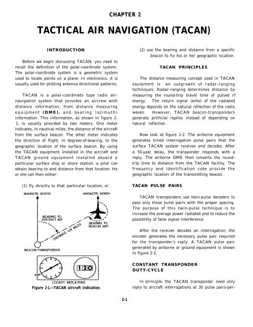
<strong>TACAN</strong> is a polar-coordinate type radio airnavigation<br />
system that provides an aircrew with<br />
distance information, from distance measuring<br />
equipment (DME), and bearing (azimuth)<br />
information. This information, as shown in figure 2-<br />
1, is usually provided by two meters. One meter<br />
indicates, in nautical miles, the distance of the aircraft<br />
from the surface beacon. The other meter indicates<br />
the direction of flight, in degrees-of-bearing, to the<br />
geographic location of the surface beacon. By using<br />
the <strong>TACAN</strong> equipment installed in the aircraft and<br />
<strong>TACAN</strong> ground equipment installed aboard a<br />
particular surface ship or shore station, a pilot can<br />
obtain bearing to and distance from that location. He<br />
or she can then either:<br />
(1) fly directly to that particular location, or<br />
(2) use the bearing and distance from a specific<br />
beacon to fix his or her geographic location.<br />
<strong>TACAN</strong> PRINCIPLES<br />
The distance measuring concept used in <strong>TACAN</strong><br />
equipment is an outgrowth of radar-ranging<br />
techniques. Radar-ranging determines distance by<br />
measuring the round-trip travel time of pulsed rf<br />
energy. The return signal (echo) of the radiated<br />
energy depends on the natural reflection of the radio<br />
waves. However, <strong>TACAN</strong> beacon-transponders<br />
generate artificial replies instead of depending on<br />
natural reflection.<br />
Now look at figure 2-2. The airborne equipment<br />
generates timed interrogation pulse pairs that the<br />
surface <strong>TACAN</strong> system receives and decodes. After<br />
a 50-µsec delay, the transponder responds with a<br />
reply. The airborne DME then converts the roundtrip<br />
time to distance from the <strong>TACAN</strong> facility. The<br />
frequency and identification code provide the<br />
geographic location of the transmitting beacon.<br />
<strong>TACAN</strong> PULSE P<strong>AIR</strong>S<br />
<strong>TACAN</strong> transponders use twin-pulse decoders to<br />
pass only those pulse pairs with the proper spacing.<br />
The purpose of this twin-pulse technique is to<br />
increase the average power radiated and to reduce the<br />
possibility of false signal interference.<br />
After the receiver decodes an interrogation, the<br />
encoder generates the necessary pulse pair required<br />
for the transponder’s reply. A <strong>TACAN</strong> pulse pair<br />
generated by airborne or ground equipment is shown<br />
in figure 2-3.<br />
CONSTANT TRANSPONDER<br />
DUTY-CYCLE<br />
Figure 2-1.—<strong>TACAN</strong> aircraft indication.<br />
In principle,<br />
reply to aircraft<br />
the <strong>TACAN</strong> transponder need only<br />
interrogations at 30 pulse pairs-per-<br />
2-1
Figure 2-2.—Distance measuring round-trip travel time.<br />
second, per airborne equipment, to supply the<br />
necessary distance data. However, the total pulse<br />
out put of the transmitter constantly varies, according<br />
to the number of interrogating aircraft. In addition,<br />
random noise may trigger the transmitter.<br />
transmitter, as shown in figure 2-4. If few<br />
interrogations are being received, the gain and squitter<br />
of the receiver increase and add noise-generated pulses<br />
to the pulse train. If more interrogating aircraft come<br />
into range, the gain and squitter decrease and reduce<br />
the number of noise-generated pulses.<br />
The relationship between the gain and the number<br />
of pulses is such that only a 2-dBm change in<br />
sensitivity occurs between reception from 1 aircraft<br />
and those from 100 aircraft. An added advantage of<br />
using a constant duty cycle is that overall transmitter<br />
power drain remains constant.<br />
BEACON-TRANSPONDER<br />
IDENTIFICATION CODE<br />
Figure 2-3.—<strong>TACAN</strong> pulse train.<br />
For the transponder to provide azimuth<br />
information, the average power supplied to the<br />
antenna must be relatively uniform over time. To<br />
accomplish this, the transponder is operated on the<br />
constant-duty-cycle principle.<br />
In this method of operation, the receiver uses<br />
automatic gain and squitter (noise generated output)<br />
controls to maintain a constant pulse output to the<br />
Before an aircrew can use <strong>TACAN</strong> information<br />
that its equipment receives, it must positively identify<br />
the transmitting <strong>TACAN</strong> station. To meet this need,<br />
the ground station transmits an identification code at<br />
approximately one-half minute intervals. It does this<br />
by momentarily interrupting the transponder distance<br />
data and squitter-generated output with pulse groups<br />
spaced at a 1350-pps rate. Each pulse group contains<br />
two sets of 12-µsec pulse pairs spaced 100 µsec apart.<br />
The duration of the identification pulse groups varies,<br />
to represent Morse-coded characters. The duration<br />
for a dot is 100 to 125 ms, and for a dash 300 to 375<br />
ms. An identification group is shown in figure 2-4.<br />
2-2
Figure 2-4.—Transponder output pulse train.<br />
15-HZ-BEARING INFORMATION<br />
The rf energy from the <strong>TACAN</strong> transmitter is fed<br />
to the antenna central element, which has no<br />
The timing of the transmitted pulses supplies the directivity in the horizontal plane. Parasitic elements<br />
actual distance information to the aircraft. This leaves positioned around the central element are<br />
amplitude modulation as another medium for the electronically rotated (switched on and off) at 15<br />
transponder to convey other information to the revolutions per minute. (See the section below on the<br />
aircraft. The <strong>TACAN</strong> beacon-transponder modulates OE-273(V)/URN antenna group). The distance<br />
the strength of the pulse to convey bearing information between the central element and the parasitic elements<br />
by producing a specific directional-radiating pattern is selected to obtain a cardioid radiation pattern. To<br />
rotated around a vertical axis. This signal, when an aircraft at a specific location, the distance data<br />
properly referenced, indicates the aircraft’s direction pulses appear to contain a 15-Hz amplitude-modulated<br />
from the <strong>TACAN</strong> facility. This signal and distance signal because of the rotation of the cardioid radiation<br />
data give a two-piece fix (distance and direction) for pattern. This pattern is shown in figure 2-5, view A<br />
determining specific aircraft location. and view B.<br />
2-3
section on the OE-273(V)/URN antenna group).<br />
Electronically switching these elements modifies the<br />
antenna cardioid pattern. Though the cardioid pattern<br />
is still predominant, it is altered by superimposed<br />
ripples. The aircraft now receives the 15-Hz signal<br />
with a 135-Hz ripple amplitude modulated on the<br />
distance data pulses (figure 2-6).<br />
To furnish a suitable reference for measuring the<br />
phase of the 135-Hz component of the envelope wave,<br />
the transponder is designed to transmit a coded 135-<br />
Hz reference burst similar to that explained for the 15-<br />
Hz reference. The 135-Hz reference group is<br />
commonly referred to as the auxiliary or aux reference<br />
burst.<br />
The composite <strong>TACAN</strong> signal is composed of<br />
2700 interrogation replies and noise pulse<br />
pairs-per-second, plus 180 North burst pulse<br />
pairs-per-second, 720 auxiliary burst pulse pairs-persecond,<br />
for a total of 3600 pulse pairs-per-second, or<br />
7200 pulses-per-second.<br />
<strong>TACAN</strong> SIGNAL PRIORITIES<br />
Figure 2-5.—<strong>TACAN</strong> radiation pattern: A. cardioid<br />
pattern; B. Ampltitude-modulated pulse pairs.<br />
The aircraft <strong>TACAN</strong> equipment obtains bearing<br />
information by comparing the 15-Hz modulated signal<br />
with a 15-Hz reference burst signal it receives from the<br />
ground facility. The phase relationship between the<br />
15-Hz modulated signal and the 15-Hz reference burst<br />
signal depends on the location of the aircraft in the<br />
cardioid pattern. The 15-Hz reference burst signals<br />
are transmitted when the maximum signal of the<br />
cardioid pattern aims due East. This group of 12 pulse<br />
pairs is commonly referred to as the North or main<br />
reference burst. You can see the relationship between<br />
the reference pulses and the cardioid pattern by<br />
comparing view A and view B of figure 2-5.<br />
135-HZ BEARING INFORMATION<br />
Priorities have been established for transmission of<br />
the various types of <strong>TACAN</strong> signals. These priorities<br />
are as follows:<br />
1.<br />
2.<br />
3.<br />
4.<br />
Reference bursts (North and auxiliary)<br />
Identification group<br />
Replies to interrogations<br />
Squitter<br />
Therefore, the identification group, replies, or<br />
squitter will be momentarily interrupted for the<br />
transmission of either the main or auxiliary reference<br />
group. The transmission of replies or squitter will be<br />
interrupted every 37.5 seconds during the transmission<br />
of an identification code dot or dash.<br />
Errors arising from imperfections in the phase<br />
measuring circuits and radio propagation effects are<br />
known as site error. These errors are significantly<br />
reduced by the addition of 32 outer parasitic elements<br />
added to the electronically scanned antenna. (See the<br />
CHARACTERISTICS OF<br />
RADIO BEACON SIGNALS<br />
Depending on what channel (X or Y) the <strong>TACAN</strong><br />
is on, the number of pulses-per-second and the pulse<br />
2-4
Figure 2-6.—<strong>TACAN</strong> modulation envelope<br />
spacing are a characteristic of that particular <strong>TACAN</strong><br />
signal element. However, it is important to understand<br />
that proper spacing between pulses and pulse pairs is<br />
what actually provides the aircraft with the means to<br />
distinguish between the <strong>TACAN</strong> pulses and any other<br />
pulses that might be present on the received radio<br />
frequency. Check the reference data in the appropriate<br />
technical manual for specific pulse characteristics and<br />
spacing.<br />
<strong>TACAN</strong> EQUIPMENT<br />
Many different types of <strong>TACAN</strong> equipment have<br />
been used for air navigation. Today, the AN/URN-25<br />
is taking over the task of tactical air navigation from<br />
the older AN/URN-20 on new construction ships and<br />
as ships complete overhaul. Two types of antennas<br />
are used with the AN/URN-25. They are the OE-<br />
273(V)/URN, used primarily in shipboard installations,<br />
and the OE-258/URN, which is used primarily ashore.<br />
Because both antenna systems are similar in theory of<br />
operation, we will discuss only the OE-273/URN. In<br />
the following paragraphs, we will discuss the<br />
AN/URN-25 and the antenna group 0E-273(V)/URN,<br />
and then we will briefly discuss the AN/URN-20.<br />
<strong>TACAN</strong> SET AN/URN-25<br />
The AN/URN-25 <strong>TACAN</strong> is used as a groundbased<br />
or shipborne beacon transponder to provide<br />
range and bearing information to aircraft equipped<br />
with <strong>TACAN</strong> equipment. It consists of two major<br />
units: the Transponder Group OX-52/URN-25,<br />
commonly referred to as unit 1, and the Control-<br />
Indicator C-10363/URN-25, commonly referred to as<br />
unit 2. These units are shown in figure 2-7. Each<br />
transponder is housed in a cabinet with two vertical<br />
drawers, one containing a coder keyer and the other<br />
containing a receiver-transmitter.<br />
The control-indicator displays the status of the<br />
transponder(s) and failure alarms, and allows limited<br />
control of the transponder(s) from a remote location.<br />
2-5
2-6
It may be mounted in its own cabinet or in a standard<br />
19-inch rack.<br />
To increase the channels available, the <strong>TACAN</strong> set<br />
can be operated in either the X or Y mode. The Y<br />
mode changes the pulse pair spacing and the auxiliary<br />
burst count and spacing, and increases system delay.<br />
ANTENNA GROUP OE-273(V)/URN<br />
Shown in figure 2-8, the Antenna Group OE-<br />
273/URN is a solid-state, high-performance,<br />
electronically-scanned, all-band <strong>TACAN</strong> antenna<br />
system, complete with integral monitoring system and<br />
built-in fault isolation capability. The antenna group<br />
develops the coarse and fine bearing modulations<br />
electronically.<br />
Rather than forming the <strong>TACAN</strong> radiation pattern<br />
by the old mechanical rotation method, the AS-3240<br />
achieves the same effect by digital switching of<br />
parasitic elements arranged in concentric arrays<br />
around the central radiator. Twelve inner elements<br />
provide the 15-Hz modulation (replacing the singlephase<br />
rotating parasitic element in the mechanically<br />
rotated antenna), and 32 outer elements provide the<br />
135-Hz modulation (replacing the nine outer elements<br />
of the rotated antenna). The 15- and 135-Hz<br />
modulation pattern is provided by electronically<br />
switching the diodes in each of the parasitic elements<br />
in prescribed time sequence, which is repeated once in<br />
each 15-Hz interval.<br />
In effect, the elements are rotated electrically,<br />
rather than mechanically. An advantage this provides<br />
is the elimination of the bandwidth limitations inherent<br />
in the old mechanically-rotated antennas. In the<br />
electronically-scanned antenna, the appropriate ring<br />
for a given frequency segment is activated by a fast<br />
electronic switch, based on information from the<br />
<strong>TACAN</strong> frequency synthesizer. This allows<br />
instantaneous band switching and all-band operation.<br />
Figure 2-8.—Antenna Group OE-273(V)/URN.<br />
2-7
Figure 2-9.—<strong>TACAN</strong> Set AN/URN-20(V)1.<br />
2-8
<strong>TACAN</strong> SET AN/URN-20<br />
Though not modern by any standard, the<br />
AN/URN-20 <strong>TACAN</strong> set is reliable and operates<br />
similarly to the AN/URN-25. Shown in figure 2-9, it<br />
uses the same electronically-scanned antenna and<br />
control-indicator as the AN/URN-25. The AN/URN-<br />
20 is being replaced by the AN/URN-25.<br />
CAPABILITIES AND LIMITATIONS<br />
The <strong>TACAN</strong> set can simultaneously provide<br />
individual distance measuring service for up to 100<br />
interrogating aircraft. Of the 3,600 pulse<br />
pairs-per-second transmitted by the <strong>TACAN</strong>, 900<br />
pulse pairs (MAIN and AUXILIARY bursts) contain<br />
the bearing information; the remaining 2,700 pulse<br />
pairs are either random noise pulses, identity pulses, or<br />
replies to interrogating aircraft. Once every 30<br />
seconds, the interrogation replies and random noise<br />
pulses are interrupted for the transmission of identity<br />
pulses.<br />
In the X mode of operation, the <strong>TACAN</strong> set<br />
transmits on one of 126 discrete channel frequencies<br />
(which are 1-MHz apart) from 962 to 1024 MHz and<br />
from 1151 to 1213 MHz. In the Y mode of operation,<br />
the set transmits on one of 126 discrete channel<br />
frequencies (which are 1-MHz apart) within the range<br />
of 1025 to 1150 MHz. The navigation set receiver,<br />
operating in the 1025- to 1150-MHz range for both<br />
the X and Y modes, is always displaced 63 MHz from<br />
the transmitter frequency.<br />
The navigation set has a receiver sensitivity of -92<br />
dBm or better and a nominal peak power output of 3<br />
kilowatts at the transponder cabinet output. (Power<br />
output may limited to less than peak by directives).<br />
Since the bearing and identification signals are<br />
delivered spontaneously and not in response to<br />
interrogations, an unlimited number of properly<br />
equipped aircraft can derive this information from the<br />
<strong>TACAN</strong> set over a line-of-sight (los) range up to 200<br />
nautical miles.<br />
2-9