
You also want an ePaper? Increase the reach of your titles
YUMPU automatically turns print PDFs into web optimized ePapers that Google loves.
19096MBP<br />
Scope of Design<br />
19096MBP<br />
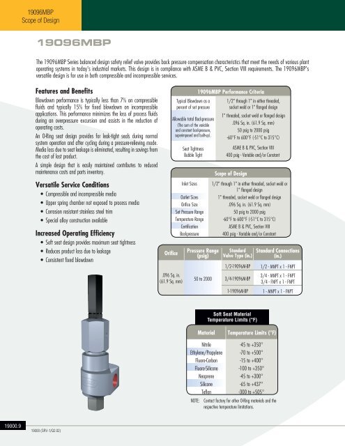
The 19096MBP Series balanced design safety relief valve provides back pressure compensation characteristics that meet the needs of various plant<br />
operating systems in today's industrial markets. This design is in compliance with ASME B & PVC, Section VIII requirements. The 19096MBP's<br />
versatile design is for use in both compressible and incompressible services.<br />
Features and Benefits<br />
Blowdown performance is typically less than 7% on compressible<br />
fluids and typically 15% for fixed blowdown on incompressible<br />
applications. This performance minimizes the loss of process fluids<br />
during an overpressure excursion and assists in the reduction of<br />
operating costs.<br />
An O-Ring seat design provides for leak-tight seals during normal<br />
system operation and after cycling during a pressure-relieving mode.<br />
Media loss due to seat leakage is eliminated, resulting in savings from<br />
the cost of lost product.<br />
A simple design that is easily maintained contributes to reduced<br />
maintenance costs and parts inventory.<br />
Versatile Service Conditions<br />
• Compressible and incompressible media<br />
• Upper spring chamber not exposed to process media<br />
• Corrosion resistant stainless steel trim<br />
• Special alloy construction available<br />
Increased Operating Efficiency<br />
• Soft seat design provides maximum seat tightness<br />
• Reduces product loss due to leakage<br />
• Consistent fixed blowdown<br />
Orifice<br />
.096 Sq. in.<br />
(61.9 Sq. mm)<br />
19096MBP Performance Criteria<br />
Typical Blowdown as a 1/2" through Liquid: 1" 6% in to either 20% threaded,<br />
percent of set pressure socket weld Gas: or 3% 1" to flanged 16% design<br />
1" threaded,<br />
Allowable total Backpressure Liquid: socket 70% of weld Set or Pressure flanged design<br />
NOTE: Thermal<br />
(The sum of the variable<br />
.096 Sq. Relief in. applications (61.9 Sq. may mm) be supplied<br />
with backpressure up to 90% of set pressure.<br />
and constant backpressure,<br />
Gas: 5050% psig to of 2000 Set Pressure psig<br />
superimposed and built-up).<br />
-60°F to 600°F (-51°C to 315°C)<br />
Set Pressure of 50 psig: 92%;<br />
Seat Tightness<br />
ASME B & PVC, Section VIII<br />
51 psig to 100 psig: 94%;<br />
Bubble Tight<br />
400<br />
101<br />
psig<br />
psig<br />
-<br />
to<br />
Variable<br />
Maximum<br />
and/or<br />
Rating:<br />
Constant<br />
97%<br />
Inlet Sizes<br />
Outlet Sizes<br />
Orifice Size<br />
Set Pressure Range<br />
Temperature Range<br />
Certification<br />
Backpressure<br />
Pressure Range<br />
(psig)<br />
50 to 2000<br />
Total Backpressure for liquid or gas shall not exceed 400 psig<br />
Scope of Design<br />
1/2" through 1" in either threaded, socket weld or<br />
1" flanged design<br />
1" threaded, socket weld or flanged design<br />
.096 Sq. in. (61.9 Sq. mm)<br />
50 psig to 2000 psig<br />
-60°F to 600°F (-51°C to 315°C)<br />
ASME B & PVC, Section VIII<br />
400 psig - Variable and/or Constant<br />
Standard<br />
Valve Type (in.)<br />
1/2-19096M-BP<br />
3/4-19096M-BP<br />
1-19096M-BP<br />
Standard Connections<br />
(in.)<br />
1/2 - MNPT x 1 - FNPT<br />
3/4 - MNPT x 1 - FNPT<br />
3/4 - FNPT x 1 - FNPT<br />
1 - MNPT x 1 - FNPT<br />
Soft Seat Material<br />
Temperature Limits (°F)<br />
Material<br />
Temperature Limits (°F)<br />
Nitrile<br />
Ethylene/Propylene<br />
Fluoro-Carbon<br />
Fluoro-Silicone<br />
Neoprene<br />
Silicone<br />
Teflon<br />
-45 to +350°<br />
-70 to +500°<br />
-15 to +400°<br />
-100 to +350°<br />
-45 to +300°<br />
-65 to +437°<br />
-300 to +505°<br />
NOTE: Contact factory for other O-Ring materials and the<br />
respective temperature limitations.<br />
<strong>19000</strong>.9<br />
<strong>19000</strong> (<strong>SRV</strong>-1/Q2.02)