
You also want an ePaper? Increase the reach of your titles
YUMPU automatically turns print PDFs into web optimized ePapers that Google loves.
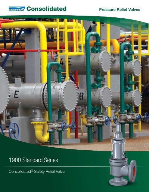
Pressure Relief <strong>Valve</strong>s<strong>1900</strong> <strong>Standard</strong> <strong>Series</strong>Consolidated ® Safety Relief <strong>Valve</strong>
Table of ContentsConversion Table . . . . . . . . . . . . . . . . . . . . . . . . . . . . . . . . . . . . . . . . . . . . . . . . . . . . . . . <strong>1900</strong>.2Features & Benefi ts . . . . . . . . . . . . . . . . . . . . . . . . . . . . . . . . . . . . . . . . . . . . . . . . . . . . . <strong>1900</strong>.3Scope of Design<strong>1900</strong> Overview. . . . . . . . . . . . . . . . . . . . . . . . . . . . . . . . . . . . . . . . . . . . . . . . . . . . . . <strong>1900</strong>.4Pressure Relief <strong>Valve</strong> Operation . . . . . . . . . . . . . . . . . . . . . . . . . . . . . . . . . . . . . . . . <strong>1900</strong>.10Product Features . . . . . . . . . . . . . . . . . . . . . . . . . . . . . . . . . . . . . . . . . . . . . . . . . . . <strong>1900</strong>.12Steam Trim (TD) <strong>Valve</strong>s. . . . . . . . . . . . . . . . . . . . . . . . . . . . . . . . . . . . . . . . . . . . . . . <strong>1900</strong>.14Liquid Trim (LA) <strong>Valve</strong>s . . . . . . . . . . . . . . . . . . . . . . . . . . . . . . . . . . . . . . . . . . . . . . . <strong>1900</strong>.15Restricted Lift <strong>Valve</strong>s . . . . . . . . . . . . . . . . . . . . . . . . . . . . . . . . . . . . . . . . . . . . . . . . <strong>1900</strong>.16Soft Seat Applications . . . . . . . . . . . . . . . . . . . . . . . . . . . . . . . . . . . . . . . . . . . . . . . <strong>1900</strong>.17MaterialsConventional Design <strong>1900</strong> <strong>Series</strong>. . . . . . . . . . . . . . . . . . . . . . . . . . . . . . . . . . . . . . . <strong>1900</strong>.20Bellows Design <strong>1900</strong>-30 <strong>Series</strong> . . . . . . . . . . . . . . . . . . . . . . . . . . . . . . . . . . . . . . . . <strong>1900</strong>.22Balanced Bellows Design <strong>1900</strong>-35. . . . . . . . . . . . . . . . . . . . . . . . . . . . . . . . . . . . . . <strong>1900</strong>.24Soft Seat (DA) . . . . . . . . . . . . . . . . . . . . . . . . . . . . . . . . . . . . . . . . . . . . . . . . . . . . . <strong>1900</strong>.26Steam Trim (TD) . . . . . . . . . . . . . . . . . . . . . . . . . . . . . . . . . . . . . . . . . . . . . . . . . . . . <strong>1900</strong>.27Liquid Trim (LA) . . . . . . . . . . . . . . . . . . . . . . . . . . . . . . . . . . . . . . . . . . . . . . . . . . . . <strong>1900</strong>.28Special Material and Service Options . . . . . . . . . . . . . . . . . . . . . . . . . . . . . . . . . . . . <strong>1900</strong>.29Sour Gas (SG) Trim . . . . . . . . . . . . . . . . . . . . . . . . . . . . . . . . . . . . . . . . . . . . . . . . . <strong>1900</strong>.29Hydrofl uoric Acid (HA) Service . . . . . . . . . . . . . . . . . . . . . . . . . . . . . . . . . . . . . . . . . <strong>1900</strong>.31Corrosive ServiceStainless Steel (S2, S3 and S4) . . . . . . . . . . . . . . . . . . . . . . . . . . . . . . . . . . . . <strong>1900</strong>.32Alloy 20 (A1, A2, A3 and A4) . . . . . . . . . . . . . . . . . . . . . . . . . . . . . . . . . . . . . . <strong>1900</strong>.34Monel (M1, M1½ (MB), M2, M3 and M4) . . . . . . . . . . . . . . . . . . . . . . . . . . . . . <strong>1900</strong>.35Hastelloy C (H1, H2, H3 and H4) . . . . . . . . . . . . . . . . . . . . . . . . . . . . . . . . . . . <strong>1900</strong>.36Duplex (D1, D2, D3 and D4) . . . . . . . . . . . . . . . . . . . . . . . . . . . . . . . . . . . . . . . <strong>1900</strong>.37Low Temperature - Process Fluid (L1, L2 and L3). . . . . . . . . . . . . . . . . . . . . . . . . . . <strong>1900</strong>.39Low Temperature - Ambient (C1 and C2) . . . . . . . . . . . . . . . . . . . . . . . . . . . . . . . . . <strong>1900</strong>.40High Temperature - (T1 and T2) . . . . . . . . . . . . . . . . . . . . . . . . . . . . . . . . . . . . . . . . <strong>1900</strong>.41Lethal Service . . . . . . . . . . . . . . . . . . . . . . . . . . . . . . . . . . . . . . . . . . . . . . . . . . . . . <strong>1900</strong>.42O-Ring Selection (Durometer by valve type and set pressure). . . . . . . . . . . . . . . . . . <strong>1900</strong>.43O-Ring Selection (Temperature limits) . . . . . . . . . . . . . . . . . . . . . . . . . . . . . . . . . . . . <strong>1900</strong>.44Accessories<strong>1900</strong> Caps, Levers, and Accessories . . . . . . . . . . . . . . . . . . . . . . . . . . . . . . . . . . . . <strong>1900</strong>.45Cap and Lever Construction . . . . . . . . . . . . . . . . . . . . . . . . . . . . . . . . . . . . . . . . . . <strong>1900</strong>.49Bolt-on Jackets . . . . . . . . . . . . . . . . . . . . . . . . . . . . . . . . . . . . . . . . . . . . . . . . . . . . <strong>1900</strong>.51Dimension & Weights. . . . . . . . . . . . . . . . . . . . . . . . . . . . . . . . . . . . . . . . . . . . . . . . . . . <strong>1900</strong>.52Pressure / Temperature Tables. . . . . . . . . . . . . . . . . . . . . . . . . . . . . . . . . . . . . . . . . . . . <strong>1900</strong>.61Capacity Tables . . . . . . . . . . . . . . . . . . . . . . . . . . . . . . . . . . . . . . . . . . . . . . . . . . . . . . . <strong>1900</strong>.91<strong>Valve</strong> Confi guration Code . . . . . . . . . . . . . . . . . . . . . . . . . . . . . . . . . . . . . . . . . . . . . . . <strong>1900</strong>.98How to Order a <strong>1900</strong> Safety Relief <strong>Valve</strong> . . . . . . . . . . . . . . . . . . . . . . . . . . . . . . . . . . . <strong>1900</strong>.101<strong>1900</strong> <strong>Series</strong> Safety Relief <strong>Valve</strong> | <strong>1900</strong>.1
Conversion TableAll the USCS values are converted toMetric values using the following conversion factors:USCS Unit Conversion Factor Metric Unitin. 25.4 mmlb. 0.4535924 kgin 2 6.4516 cm 2ft 3 /min 0.2831685 m 3 /mingal/min 3.785412 L/minlb/hr 0.4535924 kg/hrpsig 0.6894757 bargft lb 1.3558181 Nm°F 5/9 (°F-32) °C<strong>1900</strong>.2 | Dresser Consolidated ®
The Consolidated type <strong>1900</strong> Safety Relief <strong>Valve</strong> is designedto be highly adaptable in order to meet numerous applicationrequirements.Features & Benefits• Heavy duty construction provides low cost of ownership by providing longervalve service life, lower maintenance costs and easy valve conversions.• Design flexibility and parts interchangeability accommodates processchanges through easy conversion to a variety of designs.• An optional bellows design is a cost effective solution which compensatesfor the effects of variable back pressure.• A soft seat design allows to the valve to remain leak free at 95% of setpressure over 100 psig (6.89 barg) with a backup metal seat for additionalsafety.API <strong>Standard</strong> 526-2002Pressure Relief <strong>Valve</strong>s specified within this catalog comply with API <strong>Standard</strong> 526Fifth edition, 2002.When required for replacement, Consolidated <strong>1900</strong> valves are also available withconnections and dimensions in accordance with supplanted API <strong>Standard</strong> Thirdedition 1984 and prior editions.Product variations covered in subsequent pages are noted below:INLET SIZES1" (25.4 mm) through 12" (304.8 mm)INLET RATINGS ANSI Class 150 through 2500OUTLET SIZES 2" (50.8 mm) through16" (406.4 mm)OUTLET RATINGS ANSI Class 150 and 300ORIFICE SIZES Seventeen sizes: D through WTEMPERATURE RANGE -450°F (-267.8°C) to 1500°F (815.6°C)MATERIALSCast carbon steel body with stainlesssteel trim is standard.CERTIFICATIONASME B & PVC, Section II - Material (Applicable as required byASME B & PVC, Section III or VIII)ASME B & PVC, Section III, class 2 and 3 (Gas, Vapor, and LiquidService)ASME B & PVC, Section VIII (Gas, Vapor, and Liquid Service)ASME B16.34 and ASME B16.5API 520, 526 and 527ISO 4126NACE MR0103-2003 <strong>Standard</strong> Material RequirementsProductVariation<strong>1900</strong> Conventional<strong>1900</strong>-30 Bellows ConstructionDescription<strong>1900</strong>-35 Balanced Bellows with Auxiliary Balancing Piston<strong>1900</strong>HA<strong>1900</strong>SG<strong>1900</strong>DA<strong>1900</strong>LA<strong>1900</strong>DA - LA<strong>1900</strong>TDSpecial Materials for Hydrofluoric Acid ServiceSour Gas TrimSoft SeatLiquid Trim with Metallic SeatsLiquid Trim with Soft SeatsSpecial Trim for Steam & Organic Heat Transfer Media<strong>1900</strong> <strong>Series</strong> Safety Relief <strong>Valve</strong> | <strong>1900</strong>.3
Scope of Design<strong>1900</strong> <strong>Series</strong> OverviewType <strong>1900</strong> <strong>Series</strong><strong>1900</strong> <strong>Series</strong> Conventional Safety Relief <strong>Valve</strong>sConventionalSteel, Flat Seat, Top Guided, High Capacity, Stainless SteelTrimThis standard rugged configuration is equipped with corrosionresistant trim and a carbon steel body, bonnet and cap. Thecomponents are top guided, providing for free and repeatableaction.The flat disc seat provides for easy maintenance and remachining.The exclusive “Eductor Tube” minimizes bonnet cavity pressureso that product performance is predictable.The nozzle is bottom inserted and rigidly held in position,Vent Plugproviding a corrosion resistant path of flow to the valve andcorrosion resistant seating surfaces.Type <strong>1900</strong>-30 <strong>Series</strong><strong>1900</strong>-30 <strong>Series</strong> Bellows ConstructionBellowsThis valve is the same as the conventional design except that abellows has been added. When the bellows is installed, theeductor tube is removed.Caution: It is important that the bonnet be vented to theatmosphere.A bellows is added to the conventional valve to deal with any ofseveral situations:(1) Back pressure entering the valve through the valve outlet isexcessive or variable. If back pressure fluctuates with ±10%of a nominal value, a bellows is required.Vent,Do Not PlugIf a built up back pressure exceeds 10% of the set pressure orcold differential set pressure, a bellows must be used.(2) If the entering fluid is a slurry, highly viscous, or of a naturethat it can enter the critical clearances between the guides/disc holder, protect that area with a bellows.(3) If the fluid being handled is corrosive to the upper works ofthe valve, isolate the bonnet chamber through use of abellows.Conventional valves can be easily converted to a bellows designor vice versa through the use of retrofit kits.All Consolidated <strong>1900</strong>-30 <strong>Series</strong> valves are balanced bellowsdesigns, meaning that they fully compensate for the effects ofback pressure.<strong>1900</strong>.4 | Dresser Consolidated ®
Scope of Design (Contd.)<strong>1900</strong> <strong>Series</strong> Overview (Contd.)Type <strong>1900</strong>-35 <strong>Series</strong>Balanced Bellows with Auxiliary Balancing PistonVent,Do Not Plug<strong>1900</strong>-35 <strong>Series</strong> Balanced Bellows (with AuxiliaryBalancing Piston)The Balanced Bellows seals the body and fluid stream from thebonnet and working parts. Auxiliary balancing piston assuresproper valve performance by compensating for back pressurein case of bellows failure.The use of an auxiliary balanced piston is indicated when:(1) Back pressure (either constant or variable) exists and;(2) Excessive pressure may build in the bonnet as a result ofpressure build-up in the bonnet vent piping and;(3) Resultant build-up of pressure in the bonnet would causea dangerous condition.Caution: It is important that the bonnet be vented to theatmosphere.Note:Unless otherwise stated the valve is always supplied with ascrewed cap.The exception to this would be where ASMEB & PVC, Section VIII requires levers for steam, air, and hotwater service over 140°F (60°C).Refer to Accessories for available types of caps, levers, andaccessories.<strong>1900</strong> <strong>Series</strong> Safety Relief <strong>Valve</strong> | <strong>1900</strong>.5
Scope of Design (Contd.)<strong>1900</strong> <strong>Series</strong> Overview (Contd.)OrificeArea<strong>Standard</strong> <strong>Valve</strong> Connection - D OrificeAPIASMEin 2 0.110 in 2 0.128cm 2 0.710 cm 2 0.825InletOutlet<strong>Valve</strong>SizeTypeANSI Std. Size ANSI Std.in. mm Class in. mm Class1905 1.00 25.4 150 2.00 50.8 1501906 1.00 25.4 300 2.00 50.8 1501910 1.00 25.4 300 2.00 50.8 1501912 1.00 25.4 600 2.00 50.8 1501914 1.50 38.1 900 2.00 50.8 3001916 1.50 38.1 1500 2.00 50.8 3001918 1.50 38.1 2500 3.00 76.2 3001920 1.00 25.4 300 2.00 50.8 1501922 1.00 25.4 600 2.00 50.8 1501924 1.50 38.1 900 2.00 50.8 3001926 1.50 38.1 1500 2.00 50.8 3001928 1.50 38.1 2500 3.00 76.2 300OrificeArea<strong>Standard</strong> <strong>Valve</strong> Connection - E OrificeAPIASMEin 2 0.196 in 2 0.228cm 2 1.265 cm 2 1.470InletOutlet<strong>Valve</strong>SizeTypeANSI Std. Size ANSI Std.in. mm Class in. mm Class1905 1.00 25.4 150 2.00 50.8 1501906 1.00 25.4 300 2.00 50.8 1501910 1.00 25.4 300 2.00 50.8 1501912 1.00 25.4 600 2.00 50.8 1501914 1.50 38.1 900 2.00 50.8 3001916 1.50 38.1 1500 2.00 50.8 3001918 1.50 38.1 2500 3.00 76.2 3001920 1.00 25.4 300 2.00 50.8 1501922 1.00 25.4 600 2.00 50.8 1501924 1.50 38.1 900 2.00 50.8 3001926 1.50 38.1 1500 2.00 50.8 3001928 1.50 38.1 2500 3.00 76.2 300OrificeArea<strong>Standard</strong> <strong>Valve</strong> Connection - F OrificeAPIASMEin 2 0.307 in 2 0.357cm 2 1.981 cm 2 2.302InletOutlet<strong>Valve</strong>SizeTypeANSI Std. Size ANSI Std.in. mm Class in. mm Class1905 1.50 38.1 150 2.00 50.8 1501906 1.50 38.1 300 2.00 50.8 1501910 1.50 38.1 300 2.00 50.8 1501912 1.50 38.1 600 2.00 50.8 1501914 1.50 38.1 900 3.00 76.2 3001916 1.50 38.1 1500 3.00 76.2 3001918 1.50 38.1 2500 3.00 76.2 3001920 1.50 38.1 300 2.00 50.8 1501922 1.50 38.1 600 2.00 50.8 1501924 1.50 38.1 900 3.00 76.2 3001926 1.50 38.1 1500 3.00 76.2 3001928 1.50 38.1 2500 3.00 76.2 300OrificeArea<strong>Standard</strong> <strong>Valve</strong> Connection - G OrificeAPIASMEin 2 0.503 in 2 0.585cm 2 3.245 cm 2 3.774InletOutlet<strong>Valve</strong>SizeTypeANSI Std. Size ANSI Std.in. mm Class in. mm Class1905 1.50 38.1 150 3.00 76.2 1501906 1.50 38.1 300 3.00 76.2 1501910 1.50 38.1 300 3.00 76.2 1501912 1.50 38.1 600 3.00 76.2 1501914 1.50 38.1 900 3.00 76.2 3001916 2.00 50.8 1500 3.00 76.2 3001918 2.00 50.8 2500 3.00 76.2 3001920 1.50 38.1 300 3.00 76.2 1501922 1.50 38.1 600 3.00 76.2 1501924 1.50 38.1 900 3.00 76.2 3001926 2.00 50.8 1500 3.00 76.2 3001928 2.00 50.8 2500 3.00 76.2 300<strong>1900</strong>.6 | Dresser Consolidated ®
Scope of Design (Contd.)<strong>1900</strong> <strong>Series</strong> Overview (Contd.)OrificeArea<strong>Standard</strong> <strong>Valve</strong> Connection - H OrificeAPIASMEin 2 0.785 in 2 0.913cm 2 5.065 cm 2 5.888InletOutlet<strong>Valve</strong>SizeTypeANSI Std. Size ANSI Std.in. mm Class in. mm Class1905 1.50 38.1 150 3.00 76.2 1501906 1.50 38.1 300 3.00 76.2 1501910 2.00 50.8 300 3.00 76.2 1501912 2.00 50.8 600 3.00 76.2 1501914 2.00 50.8 900 3.00 76.2 1501916 2.00 50.8 1500 3.00 76.2 3001920 2.00 50.8 300 3.00 76.2 1501922 2.00 50.8 600 3.00 76.2 1501924 2.00 50.8 900 3.00 76.2 1501926 2.00 50.8 1500 3.00 76.2 300OrificeArea<strong>Standard</strong> <strong>Valve</strong> Connection - J OrificeAPIASMEin 2 1.287 in 2 1.496cm 2 8.303 cm 2 9.652InletOutlet<strong>Valve</strong>SizeTypeANSI Std. Size ANSI Std.in. mm Class in. mm Class1905 2.00 50.8 150 3.00 76.2 1501906 2.00 50.8 300 3.00 76.2 1501910 3.00 76.2 300 4.00 101.6 1501912 3.00 76.2 600 4.00 101.6 1501914 3.00 76.2 900 4.00 101.6 1501916 3.00 76.2 1500 4.00 101.6 3001920 3.00 76.2 300 4.00 101.6 1501922 3.00 76.2 600 4.00 101.6 1501924 3.00 76.2 900 4.00 101.6 1501926 3.00 76.2 1500 4.00 101.6 300OrificeArea<strong>Standard</strong> <strong>Valve</strong> Connection - K OrificeAPIASMEin 2 1.838 in 2 2.138cm 2 11.858 cm 2 13.794InletOutlet<strong>Valve</strong>SizeTypeANSI Std. Size ANSI Std.in. mm Class in. mm Class1905 3.00 76.2 150 4.00 101.6 1501906 3.00 76.2 300 4.00 101.6 1501910 3.00 76.2 300 4.00 101.6 1501912 3.00 76.2 600 4.00 101.6 1501914 3.00 76.2 900 6.00 152.4 1501916 3.00 76.2 1500 6.00 152.4 3001920 3.00 76.2 300 4.00 101.6 1501922 3.00 76.2 600 4.00 101.6 1501924 3.00 76.2 900 6.00 152.4 1501926 3.00 76.2 1500 6.00 152.4 300OrificeArea<strong>Standard</strong> <strong>Valve</strong> Connection - L OrificeAPIASMEin 2 2.853 in 2 3.317cm 2 18.406 cm 2 21.400InletOutlet<strong>Valve</strong>SizeTypeANSI Std. Size ANSI Std.in. mm Class in. mm Class1905 3.00 76.2 150 4.00 101.6 1501906 3.00 76.2 300 4.00 101.6 1501910 4.00 101.6 300 6.00 152.4 1501912 4.00 101.6 600 6.00 152.4 1501914 4.00 101.6 900 6.00 152.4 1501916 4.00 101.6 1500 6.00 152.4 1501920 4.00 101.6 300 6.00 152.4 1501922 4.00 101.6 600 6.00 152.4 1501924 4.00 101.6 900 6.00 152.4 1501926 4.00 101.6 1500 6.00 152.4 150<strong>1900</strong> <strong>Series</strong> Safety Relief <strong>Valve</strong> | <strong>1900</strong>.7
Scope of Design (Contd.)<strong>1900</strong> <strong>Series</strong> Overview (Contd.)OrificeArea<strong>Standard</strong> <strong>Valve</strong> Connection - M OrificeAPIASMEin 2 3.600 in 2 4.186cm 2 23.226 cm 2 27.006InletOutlet<strong>Valve</strong>SizeTypeANSI Std. Size ANSI Std.in. mm Class in. mm Class1905 4.00 101.6 150 6.00 152.4 1501906 4.00 101.6 300 6.00 152.4 1501910 4.00 101.6 300 6.00 152.4 1501912 4.00 101.6 600 6.00 152.4 1501914 4.00 101.6 900 6.00 152.4 1501920 4.00 101.6 300 6.00 152.4 1501922 4.00 101.6 600 6.00 152.4 1501924 4.00 101.6 900 6.00 152.4 150OrificeArea<strong>Standard</strong> <strong>Valve</strong> Connection - N OrificeAPIASMEin 2 4.340 in 2 5.047cm 2 28.000 cm 2 32.561InletOutlet<strong>Valve</strong>SizeTypeANSI Std. Size ANSI Std.in. mm Class in. mm Class1905 4.00 101.6 150 6.00 152.4 1501906 4.00 101.6 300 6.00 152.4 1501910 4.00 101.6 300 6.00 152.4 1501912 4.00 101.6 600 6.00 152.4 1501914 4.00 101.6 900 6.00 152.4 1501920 4.00 101.6 300 6.00 152.4 1501922 4.00 101.6 600 6.00 152.4 1501924 4.00 101.6 900 6.00 152.4 150OrificeArea<strong>Standard</strong> <strong>Valve</strong> Connection - P OrificeAPIASMEin 2 6.380 in 2 7.417cm 2 41.161 cm 2 47.852InletOutlet<strong>Valve</strong>SizeTypeANSI Std. Size ANSI Std.in. mm Class in. mm Class1905 4.00 101.6 150 6.00 152.4 1501906 4.00 101.6 300 6.00 152.4 1501910 4.00 101.6 300 6.00 152.4 1501912 4.00 101.6 600 6.00 152.4 1501914 4.00 101.6 900 6.00 152.4 1501920 4.00 101.6 300 6.00 152.4 1501923 4.00 101.6 600 6.00 152.4 1501924 4.00 101.6 900 6.00 152.4 150OrificeArea<strong>Standard</strong> <strong>Valve</strong> Connection - Q OrificeAPIASMEin 2 11.050 in 2 12.850cm 2 71.290 cm 2 82.903InletOutlet<strong>Valve</strong>SizeTypeANSI Std. Size ANSI Std.in. mm Class in. mm Class1905 6.00 152.4 150 8.00 203.2 1501906 6.00 152.4 300 8.00 203.2 1501910 6.00 152.4 300 8.00 203.2 1501912 6.00 152.4 600 8.00 203.2 1501920 6.00 152.4 300 8.00 203.2 1501922 6.00 152.4 600 8.00 203.2 150OrificeArea<strong>Standard</strong> <strong>Valve</strong> Connection - R OrificeAPIASMEin 2 16.000 in 2 18.600cm 2 103.226 cm 2 120.000InletOutlet<strong>Valve</strong>SizeTypeANSI Std. Size ANSI Std.in. mm Class in. mm Class1905 6.00 152.4 150 8.00 203.2 1501906 6.00 152.4 300 8.00 203.2 1501910 6.00 152.4 300 10.00 254.0 1501912 6.00 152.4 600 10.00 254.0 1501920 6.00 152.4 300 8.00 203.2 1501922 6.00 152.4 600 10.00 254.0 150OrificeArea<strong>Standard</strong> <strong>Valve</strong> Connection - T OrificeAPIASMEin 2 26.000 in 2 30.210cm 2 167.742 cm 2 194.903InletOutlet<strong>Valve</strong>SizeTypeANSI Std. Size ANSI Std.in. mm Class in. mm Class1905 8.00 203.2 150 10.00 254.0 1501906 8.00 203.2 300 10.00 254.0 1501910 8.00 203.2 300 10.00 254.0 1501912 8.00 203.2 600 10.00 254.0 1501920 8.00 203.2 300 10.00 254.0 1501922 8.00 203.2 600 10.00 254.0 150<strong>1900</strong>.8 | Dresser Consolidated ®
Scope of Design (Contd.)<strong>1900</strong> <strong>Series</strong> Overview (Contd.)OrificeArea<strong>Standard</strong> <strong>Valve</strong> Connection - U OrificeAPIASMEin 2 N/A in 2 35.099cm 2 N/A cm 2 226.445InletOutlet<strong>Valve</strong>SizeTypeANSI Std. Size ANSI Std.in. mm Class in. mm Class1905 8.00 203.2 150 10.00 254.0 1501906 8.00 203.2 300 10.00 254.0 1501910 8.00 203.2 300 10.00 254.0 1501920 8.00 203.2 300 10.00 254.0 150OrificeArea<strong>Standard</strong> <strong>Valve</strong> Connection - V OrificeAPIASMEin 2 N/A in 2 50.260cm 2 N/A cm 2 324.257InletOutlet<strong>Valve</strong>SizeTypeANSI Std. Size ANSI Std.in. mm Class in. mm Class1905 10.00 254.0 150 14.00 355.6 1501906 10.00 254.0 300 14.00 355.6 1501910 10.00 254.0 300 14.00 355.6 1501920 10.00 254.0 300 14.00 355.6 150OrificeArea<strong>Standard</strong> <strong>Valve</strong> Connection - W OrificeAPIASMEin 2 N/A in 2 78.996cm 2 N/A cm 2 509.651InletOutlet<strong>Valve</strong>SizeTypeANSI Std. Size ANSI Std.in. mm Class in. mm Class1905 12.00 304.8 150 16.00 406.4 1501906 12.00 304.8 300 16.00 406.4 1501910 12.00 304.8 300 16.00 406.4 1501920 12.00 304.8 300 16.00 406.4 150<strong>1900</strong> <strong>Series</strong> Safety Relief <strong>Valve</strong> | <strong>1900</strong>.9
Scope of Design (Contd.)How Pressure Relief <strong>Valve</strong>s OperateAll pressure relief valves operate on the principle of inletsystem pressure overcoming a spring load, allowing thevalve to relieve a defined capacity.Figure <strong>1900</strong>.1 - Closedpressure can now act over a larger area, an additional force isavailable to overcome the spring force. By adjusting the“adjusting ring” the opening in the secondary annular orifice canbe altered, thus controlling pressure build-up in chamber (B).This controlled pressure build-up in chamber (B) will overcomethe spring force causing the disc to move away from the nozzleseat and the valve to “pop” open.SpringDiscFigure <strong>1900</strong>.3 - Fully OpenASecondaryAnnular OrificeCWhen the valve is closed during normal operation (SeeFigure <strong>1900</strong>.1), the vessel pressure acting against theseating surfaces (area A) is resisted by the spring force. Asvessel pressure increases, the pressure at (A) tends toequalize the spring force and the pressure holding the seatstogether approaches zero.HuddlingChamberFigure <strong>1900</strong>.2 - Partially OpenPrimary OrificeSecondaryAnnular OrificeHuddlingChamberChamber BDisc HolderAdjusting RingOnce the valve has opened an additional pressure build-up at(C) occurs. (See Figure <strong>1900</strong>.3.) This is due to the sudden flowincrease and the restriction to flow through another annularorifice formed between the inner edge of the disc holder andthe outside diameter of the adjusting ring. These additionalforces at (C) cause the disc to lift substantially at “pop”.Flow is restricted by the opening between the nozzle seat anddisc seat until the disc seat has been lifted from the nozzle seatapproximately one-quarter of the nozzle throat diameter. Afterthe disc has attained this degree of lift, flow is then restrictedby the primary orifice rather than by the area between theseating surfaces.In vapor or gas service the valve may “simmer” before it will“pop”. When the vessel pressure increases to within one totwo percent of the set pressure, media will audibly movepast the seating surfaces into Chamber (B). As a result ofrestriction of flow in the secondary annular orifice, pressurebuilds up in Chamber (B) (See Figure <strong>1900</strong>.2). SinceBlowdown (the difference between opening and closingpressure) can be controlled within limits by positioning thesingle adjusting ring. Blowdown is caused by the result of thespring force not being able to overcome the summation of theforces at (A), (B), and (C) until the pressure at (A) drops belowthe set pressure.<strong>1900</strong>.10 | Dresser Consolidated ®
Scope of Design (Contd.)How Pressure Relief <strong>Valve</strong>s OperateFigure <strong>1900</strong>.4SpindleEductor TubeGuideDisc HolderDiscAdjusting RingAdjusting Ring PinPrimary OrificeSecondaryAnnular OrificeInlet NeckNozzleThreadsBaseNote:Figure <strong>1900</strong>.4 reflects the flow path of fluid through the valve. It is significant to recognizethat the system pressure enters through the nozzle and remains at a high pressure untilit expands through the secondary annular orifice. Pressure downstream of the secondaryannular orifice is much lower than the system pressure. The upper portion of the valvebase plus the outlet flange are of a lower pressure rating than the inlet side of the valve.Blowdown Settings: Production testing required by Manufacturers of safety relief valvesis governed by ASME Section VIII, UG-136 (d), which does not require the setting ofblowdown during production test. Adjusting rings on the <strong>1900</strong> flanged safety relief valveseries are factory adjusted to predetermined ring settings. This will provide a consistentopening and closing pressure on the safety relief valve.<strong>1900</strong> <strong>Series</strong> Safety Relief <strong>Valve</strong> | <strong>1900</strong>.11
Scope of Design (Contd.)Product Features - <strong>1900</strong> Flanged <strong>Series</strong>Adjusting RingThe adjusting ring in the Consolidated safety relief valve ispreset to predetermined positions prior to putting the valvein service. Presetting reduces the necessity of popping thevalve in service to ascertain that the ring has been setproperly for attaining the necessary lift and relieving capacity.Simple Blowdown AdjustmentAdjustment of Consolidated safety relief valve blowdown, orreseating pressure, is by means of a single adjusting ring.When moved upward, blowdown is increased (lowering thereseating pressure), or when moved downward, theblowdown is decreased (raising the reseating pressure). Thesimplicity and advantages of this adjustment are obviouswhen comparing valves having two or more adjusting ringseach of which affect valve action as well as blowdown.Minimum Guiding AreaGuiding areas greater than those required to align the seatingsurfaces are undesirable in a safety relief valve, especially thoseused in the process industries. The smaller the guiding area ofthe valve (when corrosion or contamination from the flowingmedium build up in the valve guiding surfaces) the less tendencythe guiding area will have to stick and hinder valve operation.NozzleThe nozzle is a pressure containing component in constantcontact with the process media in both the open and closedvalve positions. To ensure maximum reliability and safety,CONSOLIDATED flanged SRV nozzles are made from forgings,investment castings, or centrifugal castings.Spindle Pocket ConnectionThe connection between the spindle and disc holder in aConsolidated safety relief valve is a positive method ofattachment. The <strong>Inc</strong>onel snap ring and groove design make itvirtually impossible to remove the spindle from the disc holder,unless the ring is compressed intentionally. This designrequires a minimum amount of effort to disassemble duringmaintenance.Design SimplicityConsolidated safety relief valves embody a minimum numberof component parts which results in a savings by minimizingspare parts inventory and simplifying valve maintenance.Maximum Seat TightnessSeat finish in a safety relief valve is of the utmost importance;otherwise, valve leakage will occur.Consolidated safety relief valve seats are precision machinedand lapped. This ensures positive seating and prevents lossof contained media.The Thermodisc design provides a tighter closure andcompensates for temperature variations around the peripheryof the nozzle. Thermal distortion, which produces seatleakage, is minimized in steam service.Cap and Lever InterchangeabilityMany times it is necessary to change the type of cap or leverin the field after a valve has been installed. All Consolidatedsafety relief valves are supplied so they can be converted toany type of lever or cap desired. It is not necessary to removethe valve from the installation, nor will the set pressure beaffected when making such a change.<strong>Valve</strong> InterchangeabilityA Consolidated safety relief valve may be converted from thestandard, conventional type valve to the bellows type, or to theO-Ring seat seal type, Thermodisc seat Liquid Trim, or viceversa, requiring a minimum number of new parts. This resultsin lower costs.Quality MaterialAll Consolidated safety relief valve castings and forgings aremade to ASTM/ASME specifications and are subject tomany rigid inspections, ensuring the highest degree ofquality.Coupled with the highest quality workmanship, this ensurescontinuous protection and long, trouble-free valve life.<strong>1900</strong>.12 | Dresser Consolidated ®
Scope of Design (Contd.)Product Features - <strong>1900</strong> Flanged <strong>Series</strong>Reduction of <strong>Valve</strong> Bonnet PressureClosed bonnet valves are subject to variable pressure past the guiding surfaces when the valve is open, which adds a variable forceto that of the spring, affecting valve performance. To eliminate excess bonnet pressure and ensure good valve opening and closingaction, an Eductor Tube is provided.The Eductor Tube reduces bonnet pressure by pulling discharging fluids out of the bonnet faster than it is possible for thedischarging fluids to enter past the guiding surfaces, acting as a siphon due to the drawing effect of the flow through the outletside of the valve.Eductor Tube Reduces Bonnet PressureAn exclusive with Consolidated valves! During valve discharge, media flows through the clearance between the disc holderand guide, building up bonnet pressure. This adds a variable force to the spring force, which inhibits valve lift. Bonnetpressure is reduced by the eductor effect of the medium flowing at high velocity at the valve outlet.The greater lifting force (resulting from a reduction in bonnet pressure) introduces important advantages:(1) Response to blowdown control adjustment is uniform(2) Positive, full-rated capacity at low overpressures is assured(3) Better operation at higher back pressures with Eductor Tube.(4) Complete stability (of valve lift and capacity) is assured during operation.(5) <strong>Inc</strong>reases the lifting force when the valve opens and tends to break slight corrosive deposits or surface film whichaccumulate on the guiding surfaces and retard valve action. (For severe corrosion applications, a bellows valve isrecommended.)Figure <strong>1900</strong>.5 - Eductor TubeEductor Tube<strong>1900</strong> <strong>Series</strong> Safety Relief <strong>Valve</strong> | <strong>1900</strong>.13
Scope of Design (Contd.)<strong>1900</strong> Steam Trim (TD) <strong>Valve</strong>sThe <strong>1900</strong> TD is specifically designed for steam service andorganic heat transfer media and is certified to ASME CodeSection Vlll.Thermodisc – this is a specifically designed disc for use onhigh temperature fluids. This concept has more than 40 years offield proven performance that ensures the tightest valves in theworld.A Thermodisc is required for steam service.The Martensitic stainless steel disc construction allows for highstrength and toughness. As the set point of the valve isapproached, the pressure sealing effect of the Thermodiscassists in the tightness of the seat as does the rapid thermalequalization that occurs due to the thin sealing section.<strong>1900</strong> Steam Trim InternalsDisc HolderRetainer RingThermodiscAdjusting RingNozzle<strong>1900</strong> Disc Design AvailabilityDisc Design<strong>Valve</strong>TypeSteamLiquid<strong>Standard</strong> Solid Disc Thermodisc 1Liquid OrganicHeat TransferMediaVapor OrganicHeat TransferMediaVapor Steam LiquidLiquid OrganicHeat TransferMediaVapor OrganicHeat TransferMediaVaporASMECodeSection<strong>1900</strong> - X X X X X - - X - VIII<strong>1900</strong>-30 - X X X X X - - X - VIII<strong>1900</strong>-35 - X X X X X - - X - VIII<strong>1900</strong>/P1 2 - - - - - X 3 X 4 - X - I or VIII<strong>1900</strong>/P3 2 - - - - - X 3 - - X - I or VIIINotes:1. Thermodisc is provided in one material only, a specially heat treated martenistic stainless steel.2. Refer to the <strong>1900</strong>/P <strong>Series</strong> section for product information.3. <strong>1900</strong>/P <strong>Series</strong> are not intended for overpressure protection of power boiler drum, superheater or reheater equipment.4. Consult the factory for special conditions that require the use of an ASME Code Section I pressure relief valve.Except for liquid thermal relief applications, the “P” <strong>Series</strong> are not intended for liquid service.<strong>1900</strong>.14 | Dresser Consolidated ®
Scope of Design (Contd.)<strong>1900</strong> Liquid Trim (LA) <strong>Valve</strong>sThe Liquid Trim LA (liquid application) represents the secondgeneration of ASME B & PVC, Section VIII certified liquid trimvalves and must be used for all liquid applications for bothASME B & PVC, Section VIII certified and non-certified valves.Liquid applications have been defined as follows:(1) if the fluid remains liquid while flowing through the valve(2) if flowing fluid flashes going through the valve(3) for ASME B & PVC, Section VIII certified and non-certifiedthermal relief applications. (Thermal Relief is to preventexcessive pressure caused by thermal expansion of trappedliquids). The LA trim provides blowdown performance withranges from 7% to 12% below the set pressure. This valuablefeature provides conservation of media, a positive lift and asmooth chatter-free operation. Because of the short blowdownperformance of this design, it is critical that the inlet connectionalways provide for a pressure drop of 3% or less from thevessel to the valve as recommended by API 520.Conversion of existing <strong>1900</strong> <strong>Series</strong> valves to liquid trim isavailable through the factory or your local Green Tag Center.<strong>1900</strong> Liquid Service InternalsDisc HolderSingle piece disc holderfor maximum rigidity andpart integrity.Disc RetainerDiscNozzleAdjusting RingDesigned to provide high lift andcapacity with stable operation onliquid media.<strong>1900</strong> <strong>Series</strong> Safety Relief <strong>Valve</strong> | <strong>1900</strong>.15
Scope of Design (Contd.)<strong>1900</strong> Restricted Lift <strong>Valve</strong>sThe <strong>1900</strong> series is offered in orifice sizes ranging from the smallest “D” size to the largest “W” size. In order to accomplish certainvalve functions some special considerations have to be made. Such a case is the D and E orifice designs noted below.The D and E valves are restricted lift versions of the “F” orifice valve. The lift is restricted by a limit washer to provide theequivalent effective orifice area for a “D” or “E” orifice. This design is available with a balanced bellows configuration and isdesigned for back pressure applications.The standard <strong>1900</strong> <strong>Series</strong> are available with restricted lifts in orifices ranging from “F” to “W” for compressible media only.Restricted LiftD and E Orifice OnlyGuideLimit WasherDisc HolderConventionalLimit WasherBalanced Bellows<strong>1900</strong>.16 | Dresser Consolidated ®
Scope of Design (Contd.)Soft Seat ApplicationsCloseness of Operating Pressure to SetPressureWhere the operating pressure is close to the set pressure, seattightness can be maintained at relatively higher operatingpressures.Compressor Discharge and PositiveDisplacement Pump ServiceMechanical vibration and pressure waves could lift the valvedisc with each stroke and may cause flat metal-to-metal seatsto rub together and become damaged.The 45° metal-to-metal load bearing seats in the ConsolidatedO-Ring seat seal assure true alignment,aided by full systempressure behind the O-Ring, which effectively seals againstleakage.Corrosive ServicesIn some services, corrosion of the seating surfaces is thecause of valve leakage. In this type of service, the ConsolidatedO-Ring seat seal will protect the metal seat on the nozzleagainst contact of the corrosive fluid thereby maintaininggreater tightness.Foreign Matter and Slurry ServiceMany times foreign material such as pipe scale, weldingbeads, sand dust particles, etc. may damage the metal-tometalseating surfaces in a valve of this type when it is openand flowing.The Consolidated O-Ring seat seal is designed to absorb theimpact of most foreign particles without damage.Hot Water Boiler ServiceWhen a safety relief valve opens hot water flashes into steamat the seating surfaces and solid particles which float to thewater surface are driven against the seating surfaces at steamvelocities. Consolidated O-Ring seat seal valves can withstandthis type of service and remain tight to a greater degree thanmetal-to-metal seat valves.Consolidated uses proven quality Teflon ® O-Ring seats for thisservice. In some pressure/temperature applications, Teflon ® isnot resilient, and leakage may occur.BenefitsSafety Relief <strong>Valve</strong> leakage which is aggravated by any causeis usually costly. In many cases, expensive product is lost andmaintenance costs increased. Consolidated O-Ring seat sealvalves are designed to eliminate leakage in troublesomeapplications and reduce overall costs. Should leakage occur,it is much simpler and less expensive to replace the O-Ringthan to maintain metal-to-metal seats.O-Ring Conversion<strong>1900</strong> <strong>Series</strong> Consolidated metal seated valves can beconverted to O-Ring seat seals by installing a few basic partsprovided in a conversion kit.<strong>1900</strong>-DA soft seats without bellows<strong>1900</strong> <strong>Series</strong> Safety Relief <strong>Valve</strong> | <strong>1900</strong>.17
Scope of Design (Contd.)<strong>1900</strong> Soft Seat (DA) OptionThe Double Seal Soft SeatThe double seal design incorporates the merits of both a soft seatand a metal seat design valve. The 45° metal seat provides the loadbearing surface to transmit spring force, the slotted O-Ring retainerallows the O-Ring to be pressurized and accomplish the primarysealing function. This O-Ring seal design can be used throughout thefull pressure range of the valve. For pressure/temperature ratings ofthe seal, refer to O-Ring Selection Table in this section (pages <strong>1900</strong>.41and <strong>1900</strong>.42).Tightness: Consolidated O-Ring seat seal valves are bubble tight at95% of set pressures over 100 psig (6.89 barg).The following table reflects the percent of set pressure (poppingpressure) at which the valve will be bubble tight on air.<strong>1900</strong> Soft Seat (DA)Set PressurePercentpsigbargof Setmin. max. min. max.Pressure5 30 0.34 2.07 90%31 50 2.14 3.45 92%51 100 3.52 6.89 94%101 to max. ratingof valveBubble Tight Pressures6.96 to max. rating ofvalve95%Consolidated O-Ring seat seals provide positive closure at servicepressures closer to the set pressure than is possible with metal-tometalseats assuring continuous, trouble-free service, and completevalve tightness after numerous “pops”Note:The Consolidated <strong>1900</strong> O-Ring design features a secondarymetal-to-metal seat which becomes effective if O-Ring integrityis lost due to external fire or other causes. The retainer islapped to the nozzle at assembly assuring seat tightness.<strong>1900</strong>.18 | Dresser Consolidated ®
Scope of Design (Contd.)<strong>1900</strong> Soft Seat (DA) Option - How the Double Seal WorksTwo unique features distinguish the Consolidated O-Ring seatseal safety valve from other designs. These are the 45° metalto-metalload bearing seats and the slotted O-Ring retainer.Double SealThree Essentials to a Tighterand More Secure Seal:45°1) Concentric AlignmentThe nozzle bore and O-Ring retainer are both machined to anangle of 45°. This ensures that as the valve disc opens andcloses, the O-Ring is aligned concentrically against the lip ofthe nozzle. Close tolerance between the nozzle and the body,or the body and the disc guide and disc holder, also help toensure a tight seal when the valve is closed. Accuratealignment coupled with the load bearing function of the O-Ringretainer virtually eliminates O-Ring abrasion from valve action.2) Maximum Sealing ForceOn the back side of the O-Ring retainer there are two smallslots. When the valve is closed, process media enters betweenthe machined seat of the nozzle and the O-Ring retainer andproceeds up the slots behind the O-Ring. This pressure forcesthe O-Ring against the lip of the nozzle and the curved recessof the disc holder. As the pressure within the valve rises to setpoint, the O-Ring is pressed tightly against the nozzle tomaintain maximum sealing force until break-away pressure isreached.3) O-Ring RetentionWhen the valve opens, the pressure behind the O-Ringescapes from the same two slots on the O-Ring retainer. Thisprevents the O-Ring from being ejected. Additionally, theO-Ring encapsulating retainer prevents the O-Ring from beingpulled from its setting by the high velocity, low pressuredischarge inside the upper valve body.<strong>1900</strong> <strong>Series</strong> Safety Relief <strong>Valve</strong> | <strong>1900</strong>.19
MaterialsConventional SRV <strong>1900</strong> <strong>Series</strong><strong>1900</strong> <strong>Series</strong> Safety Relief <strong>Valve</strong> (Conventional Type)19202127111718151341171416981210740654321<strong>1900</strong>.20 | Dresser Consolidated ®
Materials (Contd.)For Gas, Vapor and Liquid Service <strong>1900</strong> <strong>Series</strong> (Conventional)PartNo.SRV <strong>1900</strong> (Conventional) (D-U Orifices)NomenclatureConventional (<strong>Standard</strong>) <strong>Valve</strong>Material (-00)1 Base(1905-1918) ASME SA216 WCC Carbon Steel(1920-1928) ASME SA217 WC6 Alloy Steel1A Base Plug(1905-1918) Carbon Steel(1920-1928) 316 Stainless Steel2 Nozzle 316 Stainless Steel3 Adjusting Ring 316 Stainless Steel4 Adjusting Ring Pin 316 Stainless Steel5 Adjusting Ring Pin Gasket Soft Iron6 DiscSolid Metal Flat Seat316 Stainless SteelThermodisc616 Stainless Steel7 Disc Retainer <strong>Inc</strong>onel X-7508 Disc Holder 316 Stainless Steel9 Guide 316 Stainless Steel10 Guide Gasket Soft Iron11 Bonnet ASME SA216 WCC Carbon Steel12 Bonnet Gasket Soft Iron13 Base Stud ASME SA193 B7 Alloy Steel14 Stud Nut ASME SA194 2H Carbon Steel15 Spindle 410 Stainless Steel16 Spindle Retainer <strong>Inc</strong>onel X-75017 Spring Washer Carbon Steel18 Spring(-450° to -76°F) 316 Stainless Steel(-75° to 800°F) Alloy Steel(801° to 1000°F) Tungsten Steel or <strong>Inc</strong>onel X-75019 Adjusting Screw 416 Stainless Steel20 Adjusting Screw Nut 416 Stainless Steel21 Screwed Cap Carbon Steel22 Bolted Cap Carbon Steel23 Packed Cap Carbon Steel24 Plain Cap Malleable Iron25 Cap Bolt Carbon Steel26 Cap Set Screw Carbon Steel27 Cap Gasket Soft Iron28 Release Nut Carbon Steel29 Release Locknut Carbon Steel30 Lever (Packed & Plain) Malleable Iron31 Lifting Fork Malleable Iron32 Lever Shaft 410/416 Stainless Steel33 Packing 316 Stainless Steel 134 Packing Nut 410/416 Stainless Steel35 Top Lever Malleable Iron36 Drop Lever Malleable Iron37 Gag Carbon Steel38 Sealing Plug Carbon Steel39 Sealing Plug Gasket Soft Iron40 Eductor Tube 316 Stainless Steel41 Bonnet Plug Carbon Steel42 Limit Washer (D-2 & E-2) 316 Stainless SteelPartNo.SRV <strong>1900</strong> (Conventional) (V & W Orifices)NomenclatureConventional(<strong>Standard</strong>) <strong>Valve</strong>Material (-00)3 Adjusting Ring 410 Stainless Steel8 Disc Holder(1905-1910) 316 Stainless Steel(1920)316 Stainless Steel(Boronized)9 Guide(1905-1910) 410 Stainless Steel(1920)316 Stainless Steel(Boronized)36 Drop Lever Carbon Steel484950515253Guide Rings (NotShown)Disc Retainer Screw(Not Shown)Retainer ScrewLocknut (Not Shown)Compression Screw(Not Shown)Compression ScrewLocknut Gasket (NotShown)Spring Plunger (NotShown)Plunger Rings (NotShown)Notes:Teflon316 Stainless Steel316 Stainless Steel616 Stainless SteelSoft Iron616 Stainless SteelTeflon1. With Flexible Graphite Fillers (Spiral Wound).<strong>1900</strong> <strong>Series</strong> Safety Relief <strong>Valve</strong> | <strong>1900</strong>.21
Materials (Contd.)Conventional SRV <strong>1900</strong>-30 <strong>Series</strong> (Bellows)<strong>1900</strong>-30 <strong>Series</strong> Safety Relief <strong>Valve</strong> (Bellows Type)2119202717111518Vent,Do Not Plug171698765421<strong>1900</strong>.22 | Dresser Consolidated ®1314121043443
Materials (Contd.)For Gas, Vapor, and Liquid Service<strong>1900</strong>-30 <strong>Series</strong>PartNo.SRV <strong>1900</strong> Bellows (D - U Orifices)Nomenclature Bellows <strong>Valve</strong> Material (-30)1 Base(1905-1918) ASME SA216 WCC Carbon Steel(1920-1928) ASME SA217 WC6 Alloy Steel1A Base Plug(1905-1918) Carbon Steel(1920-1928) 316 Stainless Steel2 Nozzle 316 Stainless Steel3 Adjusting Ring 316 Stainless Steel4 Adjusting Ring Pin 316 Stainless Steel5 Adjusting Ring Pin Gasket Soft Iron6 DiscSolid Metal Flat Seat316 Stainless SteelThermodisc616 Stainless Steel7 Disc Retainer <strong>Inc</strong>onel X-7508 Disc Holder 316 Stainless Steel9 Guide 316 Stainless Steel10 Guide Gasket Soft Iron11 Bonnet ASME SA216 WCC Carbon Steel12 Bonnet Gasket Soft Iron13 Base Stud ASME SA193 B7 Alloy Steel14 Stud Nut ASME SA194 2H Carbon Steel15 Spindle 410 Stainless Steel16 Spindle Retainer <strong>Inc</strong>onel X-75017 Spring Washer Carbon Steel18 Spring(-450° to -76°F) 316 Stainless Steel(-75° to 800°F) Alloy Steel(801° to 1000°F) Tungsten Steel or <strong>Inc</strong>onel X-75019 Adjusting Screw 416 Stainless Steel20 Adjusting Screw Nut 416 Stainless Steel21 Screwed Cap Carbon Steel22 Bolted Cap Carbon Steel23 Packed Cap Carbon Steel24 Plain Cap Malleable Iron25 Cap Bolt Carbon Steel26 Cap Set Screw Carbon Steel27 Cap Gasket Soft Iron28 Release Nut Carbon Steel29 Release Locknut Carbon Steel30 Lever (Packed & Plain) Malleable Iron31 Lifting Fork Malleable Iron32 Lever Shaft 410/416 Stainless Steel33 Packing 316 Stainless Steel 134 Packing Nut 410/416 Stainless Steel35 Top Lever Malleable Iron36 Drop Lever Malleable Iron37 Gag Carbon Steel38 Sealing Plug Carbon Steel39 Sealing Plug Gasket Soft Iron42 Limit Washer (D-2 & E-2) 316 Stainless Steel43 Bellows <strong>Inc</strong>onel 625 LCF43 Bellows Nut 316L Stainless Steel43 Bellows Flange 316L Stainless Steel44 Bellows Gasket Soft IronPartNo.SRV <strong>1900</strong> Bellows (V & W Orifices)NomenclatureBellows <strong>Valve</strong> Material(-30)3 Adjusting Ring 410 Stainless Steel8 Disc Holder(1905-1910) 316 Stainless Steel(1920) 316 Stainless Steel (Boronized)9 Guide(1905-1910) 410 Stainless Steel(1920) 316 Stainless Steel (Boronized)20 Compression Screw Nut 416 Stainless Steel36 Drop Lever Carbon Steel45 Bellows Bolts (Not Shown) ASME SA193 B7 Alloy Steel4647Bellows Bolts LockWashers (Not Shown)Overlift Restrictor (NotShown)316 Stainless Steel410 Stainless Steel48 Guide Rings (Not Shown) Teflon4950515253Disc Retainer Screw (NotShown)Retainer Screw Locknut(Not Shown)Compression Screw (NotShown)Compression ScrewLocknut Gasket (NotShown)Spring Plunger (NotShown)Plunger Rings (NotShown)Notes:316 Stainless Steel316 Stainless Steel616 Stainless SteelSoft Iron616 Stainless SteelTeflon1. With Flexible Graphite Fillers (Spiral Wound).<strong>1900</strong> <strong>Series</strong> Safety Relief <strong>Valve</strong> | <strong>1900</strong>.23
Materials (Contd.)Conventional SRV <strong>1900</strong>-35 <strong>Series</strong> (Balanced Bellows)<strong>1900</strong>-35 <strong>Series</strong> Safety Relief <strong>Valve</strong>21192027111718151314686389765466171667126265104344321<strong>1900</strong>.24 | Dresser Consolidated ®
Materials (Contd.)For Gas, Vapor, and Liquid Service <strong>1900</strong>-35 <strong>Series</strong>SRV <strong>1900</strong> Balanced BellowsSRV <strong>1900</strong> Balanced Bellows (Contd.)PartNo.NomenclatureBalanced Bellows <strong>Valve</strong>Material (-35) 1PartNo.NomenclatureBalanced Bellows <strong>Valve</strong>Material (-35) 11 Base(1905-1918) ASME SA216 WCC Carbon Steel(1920-1928) ASME SA217 WC6 Alloy Steel26 Cap Set Screw Carbon Steel27 Cap Gasket Soft Iron28 Release Nut Carbon Steel1ABase Plug(1905-1918) Carbon Steel(1920-1928) 316 Stainless Steel29 Release Locknut Carbon Steel30 Lever Malleable Iron31 Lifting Fork Malleable Iron2 Nozzle 316 Stainless Steel3 Adjusting Ring 316 Stainless Steel4 Adjusting Ring Pin 316 Stainless Steel5 Adjusting Ring Pin Gasket Soft Iron6 Disc32 Lever Shaft 410/416 Stainless Steel33 Packing 316 Stainless Steel 234 Packing Nut 410/416 Stainless Steel35 Top Lever Malleable Iron36 Drop Lever Malleable IronSolid Metal Flat SeatThermodisc316 Stainless Steel616 Stainless Steel37 Gag Carbon Steel38 Sealing Plug Carbon Steel7 Disc Retainer <strong>Inc</strong>onel X-7508 Disc Holder 316 Stainless Steel9 Guide 316 Stainless Steel10 Guide Gasket Soft Iron11 Bonnet ASME SA216 WCC Carbon Steel12 Bonnet Gasket Soft Iron13 Base Stud ASME SA193 B7 Alloy Steel14 Stud Nut ASME SA194 2H Carbon Steel15 Spindle 410 Stainless Steel16 Spindle Retainer <strong>Inc</strong>onel X-75017 Spring Washer Carbon Steel18 Spring(-450° to -76°F) 316 Stainless Steel(-75° to 800°F) Alloy Steel(801° to 1000°F) Tungsten Steel or <strong>Inc</strong>onel X-75039 Sealing Plug Gasket Soft Iron42 Limit Washer (D-2 & E-2) 316 Stainless Steel43 Bellows <strong>Inc</strong>onel 625 LCF43 Bellows Nut 316L Stainless Steel43 Bellows Flange 316L Stainless Steel44 Bellows Gasket Soft Iron62 Piston 304 Stainless Steel63 Piston Guide 316 Stainless Steel64Piston Retainer Ring(D-F only) (Not Shown)<strong>Inc</strong>onel X-75065 Seal Ring Graphitar Grade 6766 Seal Ring Expander 410 Stainless Steel67 Piston Lock Screw 18-8 Stainless Steel68 Piston Guide lock Screw 18-8 Stainless Steel69Piston Plate (D-F only)(Not Shown)316 Stainless Steel19 Adjusting Screw 416 Stainless Steel20 Adjusting Screw Nut 416 Stainless Steel21 Screwed Cap Carbon Steel22 Bolted Cap Carbon Steel23 Packed Cap Carbon Steel24 Plain Cap Malleable Iron25 Cap Bolt Carbon SteelNotes:1. Other material variations are available. Balanced pistoncomponents will be per the bellows “-30” type, except in “X3”and “X4” variations. (S3, S4, etc.). In these cases, thematerials for the piston, lock screws, seal ring expander, andpiston guide may be changed. The Seal Ring will remain asGraphitar Grade 67.2. With Flexible Graphite Fillers (Spiral Wound).<strong>1900</strong> <strong>Series</strong> Safety Relief <strong>Valve</strong> | <strong>1900</strong>.25
Materials (Contd.)<strong>1900</strong> Soft Seat (DA) Option<strong>1900</strong> Soft Seat (DA) Safety relief <strong>Valve</strong>Disc HolderRetainer Lock ScrewO-Ring Seat SealO-Ring RetainerNozzleD Thru J OrificeDisc HolderDisc RetainerDiscRetainer Lock ScrewO-Ring Seat SealO-Ring RetainerNozzleK Thru T Orifice<strong>Standard</strong> Material for <strong>1900</strong> SoftSeat (DA) Safety Relief <strong>Valve</strong>sPart Name Materials 1Disc (K-T Orifice)316 Stainless SteelDisc Holder 2316 Stainless SteelBonnetASME SA352 LCC CSDisc Retainer<strong>Inc</strong>onel X750O-Ring Retainer 3316 Stainless SteelRetainer Lock Screw (Not Shown) 3 316 Stainless SteelO-Ring Seat Seal Select 4Notes:1. Balance of Materials same as <strong>1900</strong> standard construction2. Disc Holder material for D-J orifice, will be Monel for “M” variations and Hastelloy C for “H” variations.3. O-Ring Retainer material will be Monel for “M” variations and Hastelloy C for “H” variations. The retainer lock screw will beMonel with Nylon locking feature in the “M” variations and Hastelloy C with Nylon locking feature in the “H” variations.4. Refer to pages <strong>1900</strong>.41 & <strong>1900</strong>.42 for O-Ring Selection (Durometer and Temperature Limits). See Technical InformationSection for application.<strong>1900</strong>.26 | Dresser Consolidated ®
Materials (Contd.)<strong>1900</strong> Steam Trim (TD) Option<strong>1900</strong> Steam Trim (TD) Safety Relief <strong>Valve</strong>GuideDisc HolderDisc RetainerThermodiscNozzleAdjusting RingNozzle<strong>Standard</strong> Material for <strong>1900</strong> SteamTrim (TD) Safety Relief <strong>Valve</strong>sPart Name Materials 1316 Stainless SteelThermodiscDisc RetainerDisc HolderGuideAdjusting Ring616 Stainless Steel<strong>Inc</strong>onel X750316 Stainless Steel316 Stainless Steel316 Stainless SteelNotes:1. Balance of materials same as <strong>1900</strong> standardconstruction.<strong>1900</strong> <strong>Series</strong> Safety Relief <strong>Valve</strong> | <strong>1900</strong>.27
Materials (Contd.)<strong>1900</strong> Liquid Trim (LA) Option<strong>1900</strong> Liquid Trim (LA) Safety Relief <strong>Valve</strong>Disc HolderDisc RetainerDiscAdjusting RingNozzle<strong>Standard</strong> Material for <strong>1900</strong> LiquidTrim (LA) Safety Relief <strong>Valve</strong>sPart Name Materials 1Nozzle316 Stainless SteelDisc316 Stainless SteelDisc Retainer<strong>Inc</strong>onel X750Disc Holder316 Stainless SteelGuide316 Stainless SteelAdjusting Ring316 Stainless SteelNotes:1. Balance of materials same as <strong>1900</strong> standardconstruction.<strong>1900</strong>.28 | Dresser Consolidated ®
Materials (Contd.)<strong>1900</strong> Special Material & Service OptionsThe <strong>1900</strong> Flanged <strong>Series</strong> offers various material options to satisfy customer needs and API standards. The most common optionsare listed in this section.These material options are not the only available options however. Inquire of Dresser Measurement for options not listed here.Specify the material construction classification using the construction variations such as: S2, H4, etc.Options included are:Page Number• Sour Gas Service (SG1, SG10, SG5 and SG15) <strong>1900</strong>.29• Hydrofluoric Acid Service (HA) <strong>1900</strong>.31• Stainless Steel (S2, S3 and S4) <strong>1900</strong>.32• Alloy 20 (A1, A2, A3 and A4) <strong>1900</strong>.34• Monel (M1, M1½(MB), M2, M3 and M4) <strong>1900</strong>.35• Hastelloy C (H1, H2, H3 and H4) <strong>1900</strong>.36• Duplex (D1, D2, D3 and D4) <strong>1900</strong>.37• Low Temperature - Process Fluid (L1, L2, and L3) (For media temperatures to -450°F or -268°C) <strong>1900</strong>.39• Low Temperature - Ambient (C1 and C2) (For ambient temperatures to -50°F or -45.6°C) <strong>1900</strong>.40• High Temperature (T1 & T2) (For media temperatures to 1500°F or 816°C) <strong>1900</strong>.41• Lethal Service <strong>1900</strong>.42• O-Ring Selection <strong>1900</strong>.43Many other special options are available not necessarily of a material nature. These include, but are not limited to, specialfacings on connections or special connections. Contact the factory for any special requirements you may have.<strong>1900</strong> Sour Gas (SG) TrimsMaterial requirements of NACE <strong>Standard</strong> MR0103-2003 areapplicable to systems handling sour gas if the total operatingpressure of the system is 65 psia or greater and if the partialpressure of H2S in the gas is 0.05 psia or greater.The SG10 (non-bellows) and SG15 (bellows) materialselections are satisfactory for applications in which the valvesecondary pressure (outlet side) does not exceed 65 psia (50psig (3.45 barg)). Under valve relieving conditions, 50 psig(3.45 barg) secondary pressure would not normally beexceeded until the valve set pressure exceeds 450 psig(31.03 barg).The SG1 (non-bellows) and SG5 (bellows) material selectionscomply with NACE standard MR0103-2003.Specific applications may be referred to the factory forrecommendations.<strong>1900</strong> <strong>Series</strong> Safety Relief <strong>Valve</strong> | <strong>1900</strong>.29
Materials (Contd.)<strong>1900</strong> Sour Gas (SG) Trims (Contd.)Special Materials, Sour Gas Service 1 & 2Construction VariationComponentConventional <strong>Valve</strong>sBellows <strong>Valve</strong>sSG1 3 SG10 4 SG5 3 SG15 4Base (1905-1918), Bonnet ASME SA216 WCC CS ASME SA216 WCC CS ASME SA216 WCC CS ASME SA216 WCC CSBase (1920-1928) ASME SA217 WC6 AS ASME SA217 WC6 AS ASME SA217 WC6 AS ASME SA217 WC6 ASBase Plug (1905-1918) Carbon Steel Carbon Steel Carbon Steel Carbon SteelBase Plug (1920-1928), Nozzle 316 Stainless Steel 316 Stainless Steel 316 Stainless Steel 316 Stainless SteelAdjusting Ring, Adjusting Ring Pin 316 Stainless Steel 316 Stainless Steel 316 Stainless Steel 316 Stainless SteelAdjusting Ring Pin Gasket Soft Iron Soft Iron Soft Iron Soft IronDisc - Solid Metal Flat Seat, Disc Holder 316 Stainless Steel 316 Stainless Steel 316 Stainless Steel 316 Stainless SteelDisc - Thermodisc, Disc Retainer <strong>Inc</strong>onel X-750 <strong>Inc</strong>onel X-750 <strong>Inc</strong>onel X-750 <strong>Inc</strong>onel X-750Guide, Limit Washer (D-2 & E-2) 316 Stainless Steel 316 Stainless Steel 316 Stainless Steel 316 Stainless SteelGuide Gasket, Bonnet Gasket Soft Iron Soft Iron Soft Iron Soft IronBase Stud ASME SA193 B7 AS ASME SA193 B7 AS ASME SA193 B7 AS ASME SA193 B7 ASStud Nut ASME SA194 2H CS ASME SA194 2H CS ASME SA194 2H CS ASME SA194 2H CSSpindle 316 Stainless Steel 410 Stainless Steel 410 Stainless Steel 410 Stainless SteelSpindle Retainer <strong>Inc</strong>onel X-750 <strong>Inc</strong>onel X-750 <strong>Inc</strong>onel X-750 <strong>Inc</strong>onel X-750Spring Washer 316 Stainless Steel Carbon Steel Carbon Steel Carbon SteelSpring <strong>Inc</strong>onel X-750 Alloy Steel 5 Alloy Steel 5 Alloy Steel 5Adjusting Screw, Adjusting Screw Nut 316 Stainless Steel 416 Stainless Steel 416 Stainless Steel 416 Stainless SteelScrewed Cap, Bolted Cap, Gag Carbon Steel Carbon Steel Carbon Steel Carbon SteelPacked Cap, Cap Bolt Carbon Steel Carbon Steel Carbon Steel Carbon SteelPlain Cap, Lever, Lifting Fork Malleable Iron Malleable Iron Malleable Iron Malleable IronCap Set Screw, Sealing Plug Carbon Steel Carbon Steel Carbon Steel Carbon SteelCap Gasket, Sealing Plug Gasket Soft Iron Soft Iron Soft Iron Soft IronRelease Nut, Release Locknut Carbon Steel Carbon Steel Carbon Steel Carbon SteelLever Shaft, Packing Nut 410/416 Stainless Steel 410/416 Stainless Steel 410/416 Stainless Steel 410/416 Stainless SteelPacking 316 Stainless Steel 7 316 Stainless Steel 7 316 Stainless Steel 7 316 Stainless Steel 7Top Lever, Drop Lever Malleable Iron Malleable Iron Malleable Iron Malleable IronEductor Tube 316 Stainless Steel 316 Stainless Steel Not Applicable Not ApplicableBonnet Plug Carbon Steel Carbon Steel Not Applicable Not ApplicableBellows Not Applicable Not Applicable <strong>Inc</strong>onel 625 LCF 6 <strong>Inc</strong>onel 625 LCFBellows Nut, Bellows Flange Not Applicable Not Applicable 316L Stainless Steel 316L Stainless SteelBellows Gasket Not Applicable Not Applicable Soft Iron Soft IronNotes:1. The materials in red denote variation from standard material construction.2. Compliance to NACE MR0175 requires media and materials evaluation. Please contact factory sales.3. (SG1) and (SG5) valves are for installations for compliance to NACE MR0103-2003 and prior editions.4. (SG10) and (SG15) valves are for installations where the outlet of the valve is not in a Sour Gasenvironment per NACE MR-01-75 (Pressures on the outlet side does not exceed 65 psia underrelieving conditions).5. Spring is Aluminum Metallized.6. Heat treated.7. With Flexible Graphite Fillers (Spiral Wound).<strong>1900</strong>.30 | Dresser Consolidated ®
Materials (Contd.)<strong>1900</strong> Hydrofluoric Acid (HA) ServiceTo meet the demanding requirements of the extremelycorrosive HF Alky service, Dresser Measurement has, inconjunction with major designers and users in this industry,developed the <strong>1900</strong> HA variation. Extensive use of MonelAlloy 400, in the stress relieved condition for criticalcomponents, has been utilized for this option.NACE document 5A171 states, “In practice, occurrence ofstress corrosion cracking may either be avoided by completeexclusion of oxygen or may be minimized by stress relievingwelded or cold formed parts.” The HA materials should not beconfused with the M1 through the M4 materials used for othercorrosive applications.In addition to the special stress relieved conditioned Monel400 materials, a bellows seal and litharged cured soft seathas been incorporated into this option. Long term applicationshave provided excellent results in the most severe, moist,aerated, HF Alky service.Special Materials, Hydrofluoric Acid Service (HA) 1 & 2Component Bellows <strong>Valve</strong> Material (-30)Base (1905-1918) ASME SA216 WCC CS 3Base Plug (1905-1918)Carbon SteelNozzle Monel 400 3Adjusting Ring Monel 400Adjusting Ring Pin Monel 400Adjusting Ring Pin Gasket Monel 400Disc - Solid Metal Flat Seat Monel 400 3Disc Retainer <strong>Inc</strong>onel X-750Disc Holder Monel 400 4Guide Monel 400Guide Gasket Monel 400BonnetASME SA216 WCC CSBonnet Gasket Monel 400Base Stud ASTM F468 Nickel Alloy 500Stud Nut ASTM F467 Nickel Alloy 500Spindle Monel 400Spindle Retainer <strong>Inc</strong>onel X-750Spring WasherCarbon SteelSpringCarbon Steel (Nickel Plated)Adjusting Screw Monel 400Adjusting Screw Nut Monel 400Screwed CapCarbon SteelBolted CapCarbon SteelPacked CapCarbon SteelComponent Bellows <strong>Valve</strong> Material (-30)Plain CapMalleable IronCap BoltCarbon SteelCap Set ScrewCarbon SteelCap Gasket Monel 400Release NutCarbon SteelRelease LocknutCarbon SteelLeverMalleable IronLifting ForkMalleable IronLever Shaft410 Stainless SteelPacking 316 Stainless Steel 5Packing Nut410 Stainless SteelTop LeverMalleable IronDrop LeverMalleable IronGagCarbon SteelSealing PlugCarbon SteelSealing Plug Gasket Monel 400Limit Washer (D-2 & E-2) Monel 400Bellows Monel 400 4Bellows Nut Monel 400 4Bellows Flange Monel 400 4Bellows Gasket Garlock Gylon 35101O-ring Retainer Monel 400 4Retainer Lock ScrewMonel 400 with Nylon Lock FeatureO-Ring Kalrez Spectrum 6375Notes:1. The materials in red denote variation from standard material construction.2. To specify valves, add material designation to the valve type, 1910L/HA or 1910-30L/HA.3. (<strong>Inc</strong>luding Supplement S5)PWHT is required for weld repairs per ASTM A216 paragraph 10, or if C.E. isabove 0.40. Carbon equivalent shall be determined per ASTM A216, S11.2.Weld PQR shall include hardness test of PWHT area. Test piece to confirm thatweld and weld heat-affected-zone hardnesses are 200 brinell maximum.4. Stress relieved.5. With Flexible Graphite Fillers (Spiral Wound).<strong>1900</strong> <strong>Series</strong> Safety Relief <strong>Valve</strong> | <strong>1900</strong>.31
Materials (Contd.)Corrosive ServiceCorrosive Service, Stainless Steel Material (D-U Orifice) 1&2Construction VariationComponentS2 S3 S4Common Components (-00 & -30)Base (1905-1918), Bonnet ASME SA216 WCC CS ASME SA351 CF8M SS ASME SA351 CF8M SSBase (1920-1928) ASME SA217 WC6 AS ASME SA351 CF8M SS ASME SA351 CF8M SSBase Plug (1905-1918), Release Nut, Sealing Plug Carbon Steel 316 Stainless Steel 316 Stainless SteelBase Plug (1920-1928), Nozzle 316 Stainless Steel 316 Stainless Steel 316 Stainless SteelAdjusting Ring, Adjusting Ring Pin 316 Stainless Steel 316 Stainless Steel 316 Stainless SteelAdjusting Ring Pin Gasket, Guide Gasket Monel Monel MonelDisc - Solid Metal Flat Seat, Disc Holder 316 Stainless Steel 316 Stainless Steel 316 Stainless SteelDisc - Thermodisc 616 Stainless Steel 616 Stainless Steel 616 Stainless SteelDisc Retainer, Spindle Retainer <strong>Inc</strong>onel X-750 <strong>Inc</strong>onel X-750 <strong>Inc</strong>onel X-750Guide, Limit Washer (D-2 & E-2) 316 Stainless Steel 316 Stainless Steel 316 Stainless SteelBase Stud ASME SA193 B7 AS ASME SA193 B8M SS ASME SA193 B8M SSStud Nut ASME SA194 2H CS ASME SA194 8M SS ASME SA194 8M SSSpring Washer, Release Locknut Carbon Steel Carbon Steel 316 Stainless SteelSpring (-20° to 800°F) Alloy Steel Alloy Steel 316 Stainless SteelSpring (801° to 1000°F) Tungsten Steel 3 Tungsten Steel 3 316 Stainless SteelScrewed Cap, Bolted Cap, Packed Cap Carbon Steel 316 Stainless Steel 316 Stainless SteelPlain Cap, Lifting Fork Malleable Iron 316 Stainless Steel 316 Stainless SteelCap Bolt Carbon Steel ASME SA193 B8M SS ASME SA193 B8M SSCap Set Screw Carbon Steel B8M Stainless Steel B8M Stainless SteelCap Gasket, Sealing Plug Gasket Monel Monel MonelLever, Top Lever, Drop Lever Malleable Iron Malleable Iron Malleable IronLever Shaft, Packing Nut 410/416 Stainless Steel 316 Stainless Steel 316 Stainless SteelPacking 316 Stainless Steel 4 316 Stainless Steel 4 316 Stainless Steel 4Gag Carbon Steel Carbon Steel Carbon SteelConventional (<strong>Standard</strong>) <strong>Valve</strong> Components (-00)Bonnet Gasket Monel Monel MonelSpindle, Adjusting Screw 316 Stainless Steel 316 Stainless Steel 316 Stainless SteelAdjusting Screw Nut, Eductor Tube 316 Stainless Steel 316 Stainless Steel 316 Stainless SteelBonnet Plug Carbon Steel 316 Stainless Steel 316 Stainless SteelBellows <strong>Valve</strong> Components (-30)Bonnet Gasket Soft Iron Monel MonelSpindle, Adjusting Screw 410 Stainless Steel 316 Stainless Steel 316 Stainless SteelAdjusting Screw Nut 416 Stainless Steel 316 Stainless Steel 316 Stainless SteelBellows <strong>Inc</strong>onel 625 LCF <strong>Inc</strong>onel 625 LCF <strong>Inc</strong>onel 625 LCFBellows Nut, Bellows Flange 316L Stainless Steel 316L Stainless Steel 316L Stainless SteelBellows Gasket Monel Monel MonelNotes:1. The materials in red denote variation from standard materialconstruction.2. To specify valves, add material designation to the valvetype, 1910L/S3 or 1910-30L/S3.3. or <strong>Inc</strong>onel X-7504. With Flexible Graphite Fillers (Spiral Wound).<strong>1900</strong>.32 | Dresser Consolidated ®
Materials (Contd.)Corrosive Service (Contd.)Corrosive Service, Stainless Steel Material (V & W Orifice) 1&2ComponentConstruction VariationS2 S3 S4Common Components (-00 & -30)Base(1905-1910) ASME SA216 WCC CS ASME SA351 CF8M SS ASME SA351 CF8M SSBase(1920-1928) ASME SA217 WC6 AS ASME SA351 CF8M SS ASME SA351 CF8M SSBase Plug (1905-1910), Screwed Cap, Bolted Cap Carbon Steel 316 Stainless Steel 316 Stainless SteelPacked Cap, Cap Set Screw, Release Nut Carbon Steel 316 Stainless Steel 316 Stainless SteelRelease Locknut, Sealing Plug Carbon Steel 316 Stainless Steel 316 Stainless SteelBase Plug (1920-1928), Nozzle, Adjusting Ring 316 Stainless Steel 316 Stainless Steel 316 Stainless SteelAdjusting Ring Pin, Disc - Solid Metal Flat Seat 316 Stainless Steel 316 Stainless Steel 316 Stainless SteelDisc Retainer Screw, Retainer Screw Locknut 316 Stainless Steel 316 Stainless Steel 316 Stainless SteelDisc Holder - (1905-1910), Spindle 316 Stainless Steel 316 Stainless Steel 316 Stainless SteelCompression Screw Nut, Guide (1905-1910) 316 Stainless Steel 316 Stainless Steel 316 Stainless SteelAdjusting Ring Pin Gasket, Guide Gasket, Cap Gasket Monel Monel MonelCompression Screw Locknut Gasket, Sealing Plug Gasket Monel Monel MonelDisc - Thermodisc, Spring Plunger, Compression Screw 616 Stainless Steel 616 Stainless Steel 616 Stainless SteelDisc Holder (1920-1928), Guide (1920-1928) 316 Stainless Steel (Boronized) 316 Stainless Steel (Boronized) 316 Stainless Steel (Boronized)Bonnet ASME SA216 WCC CS ASME SA351 CF8M SS ASME SA351 CF8M SSBase Stud ASME SA193 B7 Alloy Steel ASME SA193 B8M Alloy Steel ASME SA193 B8M Alloy SteelStud Nut ASME SA194 2H Carbon Steel ASME SA194 8M Carbon Steel ASME SA194 8M Carbon SteelSpring Washer, Drop Lever, Gag Carbon Steel Carbon Steel Carbon SteelSpring (-20° to 800°F) Alloy Steel Alloy Steel 316 Stainless SteelSpring (801° to 1000°F) Tungsten Steel or <strong>Inc</strong>onel X-750 Tungsten Steel or <strong>Inc</strong>onel X-750 316 Stainless SteelPlain Cap Malleable Iron 316 Stainless Steel 316 Stainless SteelCap Bolt Carbon Steel ASME SA193 B8M Alloy Steel ASME SA193 B8M Alloy SteelLever, Top Lever Malleable Iron Malleable Iron Malleable IronLifting Fork Malleable Iron 316 Stainless Steel 316 Stainless SteelLever Shaft 410/416 Stainless Steel 316 Stainless Steel 316 Stainless SteelPacking 316 Stainless Steel 3 316 Stainless Steel 3 316 Stainless Steel 3Packing Nut 410/416 Stainless Steel 316 Stainless Steel 316 Stainless SteelGuide Rings (1905-1910), Plunger Rings (Not Shown) Teflon Teflon TeflonConventional (<strong>Standard</strong>) <strong>Valve</strong> Components (-00)Bonnet Gasket Monel Monel MonelEductor Tube 316 Stainless Steel 316 Stainless Steel 316 Stainless SteelBonnet Plug Carbon Steel 316 Stainless Steel 316 Stainless SteelBellows <strong>Valve</strong> Components (-30)Bonnet Gasket Soft Iron Monel MonelLimit Washer 410 Stainless Steel 316 Stainless Steel 316 Stainless SteelBellows <strong>Inc</strong>onel 625 LCF <strong>Inc</strong>onel 625 LCF <strong>Inc</strong>onel 625 LCFBellows Nut , Bellows Flange 316L Stainless Steel 316L Stainless Steel 316L Stainless SteelBellows Gasket Monel Monel MonelBellows Bolts ASME SA193 B7 Alloy Steel ASME SA193 B8M Alloy Steel ASME SA193 B8M Alloy SteelBellows Bolts Lock Washers 316 Stainless Steel 316 Stainless Steel 316 Stainless SteelOverlift Restrictor 410 Stainless Steel 410 Stainless Steel 410 Stainless SteelNotes:1. The materials in red denote variation from standard materialconstruction.2. To specify valves, add material designation to the valvetype, 1910L/S3 or 1910-30L/S3.3. With Flexible Graphite Fillers (Spiral Wound).<strong>1900</strong> <strong>Series</strong> Safety Relief <strong>Valve</strong> | <strong>1900</strong>.33
Materials (Contd.)Corrosive Service (Contd.)Corrosive Service, Alloy 20 Material 1 & 2Construction VariationComponentA1 A2 A3 A4Common Components (-00 & -30)Base (1905-1918) ASME SA216 WCC CS ASME SA216 WCC CS ASME SA351 CN7M AS ASME SA351 CN7M ASBase (1920-1928) ASME SA217 WC6 AS ASME SA217 WC6 AS ASME SA351 CN7M AS ASME SA351 CN7M ASBase Plug (1905-1918) Carbon Steel Carbon Steel Alloy 20 3 Alloy 20Base Plug (1920-1928) 316 Stainless Steel 316 Stainless Steel Alloy 20 Alloy 20Nozzle, Disc - Solid Metal Flat Seat Alloy 20 Alloy 20 Alloy 20 Alloy 20Adjusting Ring, Adjusting Ring Pin 316 Stainless Steel Alloy 20 Alloy 20 Alloy 20Adjusting Ring Pin Gasket Soft Iron Monel Monel MonelDisc - Thermodisc, Disc Retainer <strong>Inc</strong>onel X-750 <strong>Inc</strong>onel X-750 <strong>Inc</strong>onel X-750 <strong>Inc</strong>onel X-750Disc Holder 316 Stainless Steel Alloy 20 Alloy 20 Alloy 20Guide Gasket Soft Iron Monel Monel MonelBonnet ASME SA216 WCC CS ASME SA216 WCC CS ASME SA351 CN7M AS ASME SA351 CN7M ASBase Stud ASME SA193 B7 AS ASME SA193 B7 AS Alloy 20 Alloy 20Stud Nut ASME SA194 2H CS ASME SA194 2H CS Alloy 20 Alloy 20Spindle Retainer <strong>Inc</strong>onel X-750 <strong>Inc</strong>onel X-750 <strong>Inc</strong>onel X-750 <strong>Inc</strong>onel X-750Spring Washer Carbon Steel Carbon Steel Carbon Steel Alloy 20Spring (-20° to 800°F) Alloy Steel Alloy Steel Alloy Steel Alloy 20Spring (801° to 1000°F) Tungsten Steel 4 Tungsten Steel 4 Tungsten Steel 4 Alloy 20Packed Cap Carbon Steel Carbon Steel Alloy 20 Alloy 20Plain Cap Malleable Iron Malleable Iron Not Applicable Not ApplicableCap Bolt, Sealing Plug Carbon Steel Carbon Steel Alloy 20 Alloy 20Cap Set Screw Carbon Steel Carbon Steel Not Applicable Not ApplicableCap Gasket Soft Iron Monel Monel MonelRelease Nut, Release Locknut Carbon Steel Carbon Steel Carbon Steel Carbon SteelLever, Lifting Fork Malleable Iron Malleable Iron Malleable Iron Malleable IronLever Shaft 410/416 Stainless Steel 410/416 Stainless Steel 410/416 Stainless Steel 410/416 Stainless SteelPacking 316 Stainless Steel 5 316 Stainless Steel 5 316 Stainless Steel 5 316 Stainless Steel 5Packing Nut 410/416 Stainless Steel 410/416 Stainless Steel 410/416 Stainless Steel 410/416 Stainless SteelTop Lever, Drop Lever Malleable Iron Malleable Iron Not Applicable Not ApplicableGag Carbon Steel Carbon Steel Carbon Steel Carbon SteelSealing Plug Gasket Soft Iron Monel Monel MonelConventional (<strong>Standard</strong>) <strong>Valve</strong> Components (-00)Guide 316 Stainless Steel Alloy 20 Alloy 20 Alloy 20Bonnet Gasket Soft Iron Monel Monel MonelSpindle 410 Stainless Steel Alloy 20 Alloy 20 Alloy 20Adjusting Screw, Adjusting Screw Nut 416 Stainless Steel Alloy 20 Alloy 20 Alloy 20Screwed Cap, Bolted Cap, Bonnet Plug Carbon Steel Carbon Steel Alloy 20 Alloy 20Eductor Tube 316 Stainless Steel 316 Stainless Steel Alloy 20 Alloy 20Limit Washer (D-2 & E-2) 316 Stainless Steel Alloy 20 Alloy 20 Alloy 20Bellows <strong>Valve</strong> Components (-30)Guide 316 Stainless Steel 316 Stainless Steel Alloy 20 Alloy 20Bonnet Gasket Soft Iron Soft Iron Monel MonelSpindle 410 Stainless Steel 410 Stainless Steel Alloy 20 Alloy 20Adjusting Screw, Adjusting Screw Nut 416 Stainless Steel 416 Stainless Steel Alloy 20 Alloy 20Screwed Cap, Bolted Cap Carbon Steel Carbon Steel Carbon Steel Alloy 20Limit Washer (D-2 & E-2) 316 Stainless Steel Alloy 20 Alloy 20 Alloy 20Bellows <strong>Inc</strong>onel 625 LCF Alloy 20 Alloy 20 Alloy 20Bellows Nut, Bellows Flange 316L Stainless Steel Alloy 20 Alloy 20 Alloy 20Bellows Gasket Soft Iron Monel Monel MonelNotes:1. The materials in red denote variation from standard material construction.2. To specify valves, add material designation to the valve type, 1910L/A3 or 1910-30L/A3.3. Alloy 20 - ASTM B473 UNS N08020.4. or <strong>Inc</strong>onel X-750.5. With Flexible Graphite Fillers (Spiral Wound).<strong>1900</strong>.34 | Dresser Consolidated ®
Materials (Contd.)Corrosive Service (Contd.)Corrosive Service, Monel Material 1&2Construction VariationComponentM1 MB (M 1½ ) M2 M3 M4Common Components (-00 & -30)Base (1905-1918) ASME SA216 WCC CS ASME SA216 WCC CS ASME SA216 WCC CS ASME SA494 M35-1 NCA 3 ASME SA494 M35-1 NCA 3Base (1920-1928) ASME SA217 WC6 AS ASME SA217 WC6 AS ASME SA217 WC6 AS ASME SA494 M35-1 NCA 3 ASME SA494 M35-1 NCA 3Base Plug (1905-1918) Carbon Steel Carbon Steel Carbon Steel Monel MonelBase Plug (1920-1928) 316 Stainless Steel 316 Stainless Steel 316 Stainless Steel Monel MonelNozzle Monel Monel Monel Monel MonelAdjusting Ring, Adjusting Ring Pin 316 Stainless Steel Monel Monel Monel MonelAdjusting Ring Pin Gasket Soft Iron Monel Monel Monel MonelDisc - Solid Metal Flat Seat Monel Monel Monel Monel MonelDisc - Thermodisc, Disc Retainer <strong>Inc</strong>onel X-750 <strong>Inc</strong>onel X-750 <strong>Inc</strong>onel X-750 <strong>Inc</strong>onel X-750 <strong>Inc</strong>onel X-750Disc Holder 316 Stainless Steel Monel Monel Monel MonelGuide 316 Stainless Steel 316 Stainless Steel Monel Monel MonelGuide Gasket Soft Iron Monel Monel Monel MonelBonnet ASME SA216 WCC CS ASME SA216 WCC CS ASME SA216 WCC CS ASME SA494 M35-1 NCA 3 ASME SA494 M35-1 NCA 3Base Stud ASME SA193 B7 AS ASME SA193 B7 AS ASME SA193 B7 AS Monel K500 Monel K500Stud Nut ASME SA194 2H CS ASME SA194 2H CS ASME SA194 2H CS Monel K500 Monel K500Spindle Retainer <strong>Inc</strong>onel X-750 <strong>Inc</strong>onel X-750 <strong>Inc</strong>onel X-750 <strong>Inc</strong>onel X-750 <strong>Inc</strong>onel X-750Spring Washer Carbon Steel Carbon Steel Carbon Steel Carbon Steel MonelSpring (-450° to -21°F) Not Applicable Not Applicable Not Applicable 316 Stainless Steel <strong>Inc</strong>onel X-750Spring (-20° to 800°F) Alloy Steel Alloy Steel Alloy Steel Alloy Steel Not ApplicableSpring (801° to 1000°F) Tungsten Steel 4 Tungsten Steel 4 Tungsten Steel 4 Not Applicable Not ApplicableAdjusting Screw, Adjusting Screw Nut 416 Stainless Steel 416 Stainless Steel Monel Monel MonelScrewed Cap, Bolted Cap Carbon Steel Carbon Steel Carbon Steel Monel MonelPacked Cap, Sealing Plug Carbon Steel Carbon Steel Carbon Steel Monel MonelPlain Cap Malleable Iron Malleable Iron Malleable Iron Not Applicable Not ApplicableCap Bolt Carbon Steel Carbon Steel Carbon Steel Monel K500 Monel K500Cap Set Screw Carbon Steel Carbon Steel Carbon Steel Not Applicable Not ApplicableCap Gasket Soft Iron Monel Monel Monel MonelRelease Nut, Release Locknut Carbon Steel Carbon Steel Carbon Steel Monel MonelLever, Lifting Fork Malleable Iron Malleable Iron Malleable Iron Malleable Iron 5 Malleable Iron 5Lever Shaft, Packing Nut 410/416 Stainless Steel 410/416 Stainless Steel 410/416 Stainless Steel 410/416 Stainless Steel 410/416 Stainless SteelPacking 316 Stainless Steel 6 316 Stainless Steel 6 316 Stainless Steel 6 316 Stainless Steel 6 316 Stainless Steel 6Top Lever, Drop Lever Malleable Iron Malleable Iron Malleable Iron Not Applicable Not ApplicableGag Carbon Steel Carbon Steel Carbon Steel Carbon Steel Carbon SteelSealing Plug Gasket Soft Iron Monel Monel Monel MonelLimit Washer (D-2 & E-2) 316 Stainless Steel Monel Monel Monel MonelConventional (<strong>Standard</strong>) <strong>Valve</strong> Components (-00)Bonnet Gasket Soft Iron Monel Monel Monel MonelSpindle 410 Stainless Steel 410 Stainless Steel Monel Monel MonelEductor Tube 316 Stainless Steel 316 Stainless Steel 316 Stainless Steel Monel MonelBonnet Plug Carbon Steel Carbon Steel Carbon Steel Monel MonelBellows <strong>Valve</strong> Components (-30)Bonnet Gasket Soft Iron Soft Iron Soft Iron Monel MonelSpindle 410 Stainless Steel 410 Stainless Steel 410 Stainless Steel Monel MonelBellows <strong>Inc</strong>onel 625 LCF <strong>Inc</strong>onel 625 LCF Monel Monel MonelBellows Nut, Bellows Flange 316L Stainless Steel 316L Stainless Steel Monel Monel MonelBellows Gasket Soft Iron Monel Monel Monel MonelNotes:1. The materials in red denote variation from standard material construction.2. To specify valves, add material designation to the valve type, 1910L/M3 or 1910-30L/M3.3. Nickel Copper Alloy (Per ASME Code Case 1750-22).4. Or <strong>Inc</strong>onel X-750.5. Else Customer Specififed.6. With Flexible Graphite Filler (Spiral Wound).<strong>1900</strong> <strong>Series</strong> Safety Relief <strong>Valve</strong> | <strong>1900</strong>.35
Materials (Contd.)Corrosive Service (Contd.)Corrosive Service, Hastelloy Material 1&2Construction VariationComponentH1 H2 H3 H4Common Components (-00 & -30)Base (1905-1918) ASME SA216 WCC CS ASME SA216 WCC CS Nickel Alloy 3 Nickel Alloy 3Base (1920-1928) ASME SA217 WC6 AS ASME SA217 WC6 AS Nickel Alloy 3 Nickel Alloy 3Base Plug (1905-1918), Cap Bolt Carbon Steel Carbon Steel Hastelloy C Hastelloy CBase Plug (1920-1928) 316 Stainless Steel 316 Stainless Steel Hastelloy C Hastelloy CNozzle, Disc - Solid Metal Flat Seat Hastelloy C Hastelloy C Hastelloy C Hastelloy CAdjusting Ring, Adjusting Ring Pin 316 Stainless Steel Hastelloy C Hastelloy C Hastelloy CAdjusting Ring Pin Gasket Soft Iron Monel Monel MonelDisc - Thermodisc, Disc Retainer <strong>Inc</strong>onel X-750 <strong>Inc</strong>onel X-750 <strong>Inc</strong>onel X-750 <strong>Inc</strong>onel X-750Disc Holder 316 Stainless Steel Hastelloy C Hastelloy C Hastelloy CGuide Gasket Soft Iron Monel Monel MonelBonnet ASME SA216 WCC CS ASME SA216 WCC CS Nickel Alloy 2 Nickel Alloy 2Bonnet Gasket Soft Iron Monel Monel MonelBase Stud ASME SA193 B7 AS ASME SA193 B7 AS Hastelloy C Hastelloy CStud Nut ASME SA194 2H CS ASME SA194 2H CS Hastelloy C Hastelloy CSpindle Retainer <strong>Inc</strong>onel X-750 <strong>Inc</strong>onel X-750 <strong>Inc</strong>onel X-750 <strong>Inc</strong>onel X-750Spring Washer Carbon Steel Carbon Steel Carbon Steel Hastelloy CSpring (-450° to -76°F) 316 Stainless Steel Not Applicable Not Applicable Not ApplicableSpring (-75° to 800°F) Alloy Steel Alloy Steel Alloy Steel Hastelloy CSpring (801° to 1000°F) Tungsten Steel 4 Tungsten Steel 4 Tungsten Steel 4 Hastelloy CScrewed Cap, Bolted Cap, Carbon Steel Carbon Steel Hastelloy C Hastelloy CPacked Cap, Sealing Plug Carbon Steel Carbon Steel Hastelloy C Hastelloy CPlain Cap Malleable Iron Malleable Iron Not Applicable Not ApplicableCap Set Screw Carbon Steel Carbon Steel Not Applicable Not ApplicableCap Gasket Soft Iron Monel Monel MonelRelease Nut, Release Locknut, Gag Carbon Steel Carbon Steel Carbon Steel Carbon SteelLever Malleable Iron Malleable Iron Malleable Iron 5 Malleable Iron 5Lifting Fork, Top Lever, Drop Lever Malleable Iron Malleable Iron Malleable Iron Malleable IronLever Shaft, Packing Nut 410/416 Stainless Steel 410/416 Stainless Steel 410/416 Stainless Steel 410/416 Stainless SteelPacking 316 Stainless Steel 6 316 Stainless Steel 6 316 Stainless Steel 6 316 Stainless Steel 6Sealing Plug Gasket Soft Iron Monel Monel MonelLimit Washer (D-2 & E-2) 316 Stainless Steel Hastelloy C Hastelloy C Hastelloy C<strong>Standard</strong> Components (-00)Guide 316 Stainless Steel Hastelloy C Hastelloy C Hastelloy CSpindle 410 Stainless Steel Hastelloy C Hastelloy C Hastelloy CAdjusting Screw, Adjusting Screw Nut 416 Stainless Steel Hastelloy C Hastelloy C Hastelloy CEductor Tube 316 Stainless Steel 316 Stainless Steel Hastelloy C Hastelloy CBonnet Plug Carbon Steel Carbon Steel Hastelloy C Hastelloy CBellows Components (-30)Guide 316 Stainless Steel 316 Stainless Steel Hastelloy C Hastelloy CSpindle 410 Stainless Steel 410 Stainless Steel Hastelloy C Hastelloy CAdjusting Screw, Adjusting Screw Nut 416 Stainless Steel 416 Stainless Steel Hastelloy C Hastelloy CBellows <strong>Inc</strong>onel 625 LCF Hastelloy C Hastelloy C Hastelloy CBellows Nut, Bellows Flange 316L Stainless Steel Hastelloy C Hastelloy C Hastelloy CBellows Gasket Soft Iron Monel Monel MonelNotes:1. The materials in red denote variation from standard material construction.2. To specify valves, add material designation to the valve type, 1910L/H3 or 1910-30L/H3.3. ASME SA494 CW12MW Nickel Alloy.4. Or <strong>Inc</strong>onel X-750.5. Else Customer Specififed.6. With Flexible Graphite Filler (Spiral Wound).<strong>1900</strong>.36 | Dresser Consolidated ®
Materials (Contd.)Corrosive Service (Contd.)Duplex Material 1 & 2Construction VariationComponentD1D2Common Components (-00 & -30)Base (1905-1918) ASME SA216 WCC Carbon Steel ASME SA216 WCC Carbon SteelBase (1920-1928) ASME SA217 WC6 Alloy Steel ASME SA217 WC6 Alloy SteelBase Plug (1905-1918) Carbon Steel Carbon SteelBase Plug (1920-1928) 316 Stainless Steel 316 Stainless SteelNozzle Duplex ASME SA479 UNS 31803 3 Duplex ASME SA479 UNS 31803 3Adjusting Ring 316 Stainless Steel Duplex ASME SA479 UNS 31803 3Adjusting Ring Pin 316 Stainless Steel Duplex SA479 UNS S31803Adjusting Ring Pin Gasket Soft Iron MonelDisc - Solid Metal Flat Seat Duplex ASME SA479 UNS 31803 3 Duplex ASME SA479 UNS 31803 3Disc - Thermodisc <strong>Inc</strong>onel X-750 <strong>Inc</strong>onel X-750Disc Retainer, Spindle Retainer <strong>Inc</strong>onel X-750 <strong>Inc</strong>onel X-750Disc Holder 316 Stainless Steel Duplex ASME SA479 UNS 31803 3Guide Gasket, Cap Gasket Soft Iron MonelBonnet ASME SA216 WCC Carbon Steel ASME SA216 WCC Carbon SteelBase Stud ASME SA193 B7 Alloy Steel ASME SA193 B7 Alloy SteelStud Nut ASME SA194 2H Carbon Steel ASME SA194 2H Carbon SteelSpring Washer Carbon Steel Carbon SteelSpring (-20° to 800°F) Alloy Steel Alloy SteelSpring (801° to 1000°F) Tungsten Steel or <strong>Inc</strong>onel X-750 Tungsten Steel or <strong>Inc</strong>onel X-750Screwed Cap, Bolted Cap, Packed Cap Carbon Steel Carbon SteelPlain Cap Malleable Iron Malleable IronCap Bolt Carbon Steel Carbon SteelCap Set Screw Carbon Steel Carbon SteelRelease Nut, Release Locknut, Gag Carbon Steel Carbon SteelLever Malleable Iron Malleable IronLifting Fork Malleable Iron Malleable IronLever Shaft, Packing Nut 410/416 Stainless Steel 410/416 Stainless SteelPacking 316 Stainless Steel 4 316 Stainless Steel 4Top Lever, Drop Lever Malleable Iron Malleable IronSealing Plug Carbon Steel Carbon SteelSealing Plug Gasket Soft Iron MonelLimit Washer (D-2 & E-2) 316 Stainless Steel 316 Stainless SteelConventional (<strong>Standard</strong>) <strong>Valve</strong> Material (-00)Guide 316 Stainless Steel Duplex ASME SA479 UNS 31803 3Bonnet Gasket Soft Iron MonelSpindle 410 Stainless Steel Duplex SA479 UNS S31803Adjusting Screw, Adjusting Screw Nut 416 Stainless Steel Duplex SA479 UNS S31803Eductor Tube 316 Stainless Steel 316 Stainless SteelBonnet Plug Carbon Steel Carbon SteelBellows <strong>Valve</strong> Material (-30)Guide 316 Stainless Steel 316 Stainless SteelBonnet Gasket Soft Iron Soft IronSpindle 410 Stainless Steel 410 Stainless SteelAdjusting Screw, Adjusting Screw Nut 416 Stainless Steel 416 Stainless SteelBellows <strong>Inc</strong>onel 625 LCF <strong>Inc</strong>onel 625 LCFBellows Nut, Bellows Flange 316L Stainless Steel 316L Stainless SteelBellows Gasket Soft Iron MonelNotes:1. The materials in red denote variation from standard material construction.2. To specify valves, add material designation to the valve type, 1910L/D2 or 1910-30L/D2.3. Or SA995 UNS J93345.4. With Flexible Graphite Filler (Spiral Wound).<strong>1900</strong> <strong>Series</strong> Safety Relief <strong>Valve</strong> | <strong>1900</strong>.37
Materials (Contd.)Corrosive Service (Contd.)Duplex Material 1 & 2ComponentConstruction VariationD3D4Common Components (-00 & -30)Base (1905-1918) ASME SA995 CE8MN UNS J93345 Duplex SS ASME SA995 CE8MN UNS J93345 Duplex SSBase Plug (1905-1918) Duplex ASME SA479 UNS 31803 Duplex ASME SA479 UNS 31803Nozzle Duplex ASME SA479 UNS 31803 3 Duplex ASME SA479 UNS 31803 3Adjusting Ring Duplex ASME SA479 UNS 31803 3 Duplex ASME SA479 UNS 31803 3Adjusting Ring Pin Duplex SA479 UNS S31803 Duplex SA479 UNS S31803Adjusting Ring Pin Gasket Monel MonelDisc - Solid Metal Flat Seat Duplex ASME SA479 UNS 31803 3 Duplex ASME SA479 UNS 31803 3Disc - Thermodisc <strong>Inc</strong>onel X-750 <strong>Inc</strong>onel X-750Disc Retainer, Spindle Retainer <strong>Inc</strong>onel X-750 <strong>Inc</strong>onel X-750Disc Holder Duplex ASME SA479 UNS 31803 3 Duplex ASME SA479 UNS 31803 3Guide Gasket, Cap Gasket Monel MonelBonnet ASME SA995 CE8MN UNS J93345 Duplex ASME SA995 CE8MN UNS J93345 DuplexBase Stud ASME SA193 B8M Alloy Steel ASME SA193 B8M Alloy SteelStud Nut ASME SA194 8M Carbon Steel ASME SA194 8M Carbon SteelSpring Washer Carbon Steel Duplex ASME SA479 UNS S31803Spring (-20° to 800°F) Alloy Steel <strong>Inc</strong>onel X-750Spring (801° to 1000°F) Tungsten Steel or <strong>Inc</strong>onel X-750 <strong>Inc</strong>onel X-750Screwed Cap, Bolted Cap, Packed Cap Duplex ASME SA479 UNS 31803 3 Duplex ASME SA479 UNS 31803 3Plain Cap Not Applicable Not ApplicableCap Bolt ASTM A193 B8M Stainless Steel ASTM A193 B8M Stainless SteelRelease Nut, Release Locknut, Gag Carbon Steel Carbon SteelLever Malleable Iron else Customer Specified Malleable Iron else Customer SpecifiedLifting Fork Malleable Iron Malleable IronLever Shaft, Packing Nut 410/416 Stainless Steel 410/416 Stainless SteelPacking 316 Stainless Steel 4 316 Stainless Steel 4Sealing Plug Duplex ASME SA479 UNS S31803 Duplex ASME SA479 UNS S31803Sealing Plug Gasket Monel MonelLimit Washer (D-2 & E-2) Duplex UNS S31803 Duplex UNS S31803Conventional (<strong>Standard</strong>) <strong>Valve</strong> Material (-00)Guide Duplex ASME SA479 UNS 31803 3 Duplex ASME SA479 UNS 31803 3Bonnet Gasket Monel MonelSpindle Duplex SA479 UNS S31803 Duplex SA479 UNS S31803Adjusting Screw, Adjusting Screw Nut Duplex SA479 UNS S31803 Duplex SA479 UNS S31803Eductor Tube ASTM A789 5 ASTM A789 5Bonnet Plug Duplex ASME SA479 UNS S31803 Duplex ASME SA479 UNS S31803Bellows <strong>Valve</strong> Material (-30)Guide 316 Stainless Steel 316 Stainless SteelBonnet Gasket Monel MonelSpindle 410 Stainless Steel 410 Stainless SteelAdjusting Screw, Adjusting Screw Nut 416 Stainless Steel 416 Stainless SteelBellows <strong>Inc</strong>onel 625 <strong>Inc</strong>onel 625Bellows Nut, Bellows Flange <strong>Inc</strong>onel 625 <strong>Inc</strong>onel 625Bellows Gasket Monel MonelNotes:1. The materials in red denote variation from standard material construction.2. To specify valves, add material designation to the valve type, 1910L/D2 or 1910-30L/D2.3. Or SA995 UNS J933454. With Flexible Graphite Filler (Spiral Wound)5. Or ASME SA789 SAF 2507 Super Duplex UNS S32750<strong>1900</strong>.38 | Dresser Consolidated ®
Materials (Contd.)Low TemperatureSpecial Materials for Low Process Fluid Temperature 1&2Construction VariationNomenclatureL1 L2 L3-21 to -75°F (-29 to -59°C) -76 to -150°F (-60 to -101°C) -151 to -450°F (-102 to -268°C)Common Components (-00 & -30)Base (1905-1918) ASME SA351 CF8M 3 ASME SA351 CF8M ASME SA351 CF8MBase Plug (1905-1918), Nozzle 316 Stainless Steel 316 Stainless Steel 316 Stainless SteelAdjusting Ring, Adjusting Ring Pin, Guide 316 Stainless Steel 316 Stainless Steel 316 Stainless SteelAdjusting Ring Pin Gasket, Sealing Plug Gasket Monel Monel MonelGuide Gasket, Bonnet Gasket, Cap Gasket Monel Monel MonelDisc - Solid Metal Flat Seat, Disc Holder 316 Stainless Steel 316 Stainless Steel 316 Stainless Steel 5Disc - Thermodisc, Disc Retainer <strong>Inc</strong>onel X-750 <strong>Inc</strong>onel X-750 <strong>Inc</strong>onel X-750Bonnet ASME SA216 WCC CS ASME SA351 CF8M ASME SA351 CF8MBase Stud ASME SA193 B8M St.St. ASME SA193 B8M St.St. ASME SA193 B8M St.St.Stud Nut ASME SA194 8M St.St. ASME SA194 8M St.St. ASME SA194 8M St.St.Spindle 410 Stainless Steel 316 Stainless Steel 316 Stainless Steel 5Spindle Retainer <strong>Inc</strong>onel X-750 <strong>Inc</strong>onel X-750 <strong>Inc</strong>onel X-750Spring Washer Carbon Steel 316 Stainless Steel 316 Stainless Steel 5Sealing Plug Carbon Steel 316 Stainless Steel 316 Stainless SteelSpring (-450° to -76°F) Not Applicable 316 Stainless Steel 316 Stainless SteelSpring (-75° to 800°F) Alloy Steel Not Applicable Not ApplicableAdjusting Screw 416 Stainless Steel 316 Stainless Steel 316 Stainless Steel 5Adjusting Screw Nut 416 Stainless Steel 316 Stainless Steel 316 Stainless SteelScrewed Cap, Bolted Cap, Packed Cap Carbon Steel 316 Stainless Steel 316 Stainless SteelPlain Cap, Lifting Fork Malleable Iron 316 Stainless Steel 316 Stainless SteelCap Bolt Carbon Steel 316 Stainless Steel ASME SA193 B8M St.St.Cap Set Screw, Release Nut, Release Locknut Carbon Steel 316 Stainless Steel 316 Stainless SteelLever, Top Lever, Drop Lever Malleable Iron Malleable Iron Malleable IronLever Shaft, Packing Nut 410/416 Stainless Steel 410/416 Stainless Steel 410/416 Stainless SteelPacking 316 Stainless Steel 4 316 Stainless Steel 4 316 Stainless Steel 4Gag Carbon Steel Carbon Steel Carbon SteelLimit Washer (D-2 & E-2) 316 Stainless Steel 316 Stainless Steel 316 Stainless SteelConventional (<strong>Standard</strong>) Components (-00)Eductor Tube 316 Stainless Steel 316 Stainless Steel 316 Stainless SteelBonnet Plug Carbon Steel 316 Stainless Steel 316 Stainless SteelBellows Components (-30)Bellows <strong>Inc</strong>onel 625 LCF <strong>Inc</strong>onel 625 LCF 316L Stainless SteelBellows Nut , Bellows Flange 316L Stainless Steel 316L Stainless Steel 316L Stainless SteelBellows Gasket Monel Monel MonelNotes:1. The materials in red denote variation from standard material construction.2. To specify valves, add material designation to the valve type, 1910L/L2 or 1910-30L/L2.3. ASME SA352 LCC can be substituted for bases down to -50°F (-45.6°C) when requested.4. With Flexible Graphite Filler (Spiral Wound).5. With Titanium Nitride Coating.<strong>1900</strong> <strong>Series</strong> Safety Relief <strong>Valve</strong> | <strong>1900</strong>.39
Materials (Contd.)Low Temperature (Contd.)Special Materials for Low Ambient Temperatures 1, 2 & 3(to -50°F or -45°C)ComponentCommon Components (-00 & -30)Construction VariationC1 C2 4Base (1905-1918) ASME SA352 LCC Carbon Steel ASME SA351 CF8M Stainless SteelBase Plug (1905-1918), Nozzle 316 Stainless Steel 316 Stainless SteelAdjusting Ring, Adjusting Ring Pin 316 Stainless Steel 316 Stainless SteelAdjusting Ring Pin Gasket, Guide Gasket Soft Iron Soft IronDisc - Solid Metal Flat Seat 316 Stainless Steel 316 Stainless SteelDisc - Thermodisc 616 Stainless Steel 616 Stainless SteelDisc Retainer, Spindle Retainer <strong>Inc</strong>onel X-750 <strong>Inc</strong>onel X-750Disc Holder, Guide, Spring Washer 316 Stainless Steel 316 Stainless SteelBonnet Gasket, Cap Gasket, Sealing Plug Gasket Soft Iron Soft IronBonnet ASME SA352 LCC Carbon Steel ASME SA351 CF8M Stainless SteelBase Stud ASME SA193 B8M Stainless Steel ASME SA193 B8M Stainless SteelStud Nut ASME SA194 8M Stainless Steel ASME SA194 8M Stainless SteelSpindle 410 Stainless Steel 410 Stainless SteelSpring (-50° to 800°F) Alloy Steel Alloy SteelAdjusting Screw, Adjusting Screw Nut 416 Stainless Steel 416 Stainless SteelScrewed Cap, Bolted Cap, Packed Cap LCC Carbon Steel LCC Carbon SteelPlain Cap, Lever, Lifting Fork, Top Lever, Drop Lever Malleable Iron Malleable IronCap Bolt, Gag, Sealing Plug Carbon Steel Carbon SteelCap Set Screw, Limit Washer (D-2 & E-2) 316 Stainless Steel 316 Stainless SteelRelease Nut, Release Locknut Carbon Steel Carbon SteelLever Shaft, Packing Nut 410/416 Stainless Steel 410/416 Stainless SteelPacking 316 Stainless Steel 5 316 Stainless Steel 5Conventional (<strong>Standard</strong>) <strong>Valve</strong> Components (-00)Eductor Tube 316 Stainless Steel 316 Stainless SteelBonnet Plug 316 Stainless Steel 316 Stainless SteelBellows <strong>Valve</strong> Components (-30)Bellows <strong>Inc</strong>onel 625 LCF <strong>Inc</strong>onel 625 LCFBellows Nut, Bellows Flange 316L Stainless Steel 316L Stainless SteelBellows Gasket Soft Iron Soft IronNotes:1. The materials in red denote variation from standard material construction.2. Media temperature may impact valve temperature. Contact factory for assistance.3. To specify valves, add material designation to the valve type, 1910L/C1 or 1910-30L/C1.4. If impact testing is required, use the “C1” material variation.5. With Flexible Graphite Filler (Spiral Wound).<strong>1900</strong>.40 | Dresser Consolidated ®
Materials (Contd.)High TemperatureSpecial Materials for Low Process Fluid Temperature 1 & 2T1 T2 3 and 4Component1001 to 1200°F (538°C to 649°C) 1201 to 1500°F (649 to 815°C)<strong>Standard</strong> <strong>Valve</strong> Material (-00) Bellows <strong>Valve</strong> Material (-30) <strong>Standard</strong> <strong>Valve</strong> Material (-00)Base(1920-1928) ASME SA351 CF8M St.St. ASME SA351 CF8M St.St. ASME SA351 CF8M St.St. 5Base Plug(1920-1928), Nozzle 316 Stainless Steel 316 Stainless Steel 316 Stainless SteelAdjusting Ring, Adjusting Ring Pin 316 Stainless Steel 316 Stainless Steel 316 Stainless SteelAdjusting Ring Pin Gasket, Guide Gasket Monel Monel MonelDisc - Solid Metal Flat Seat 316 Stainless Steel 316 Stainless Steel <strong>Inc</strong>onel X-750Disc - Thermodisc, Disc Retainer <strong>Inc</strong>onel X-750 <strong>Inc</strong>onel X-750 <strong>Inc</strong>onel X-750Disc Holder 316 Stainless Steel 6 316 Stainless Steel 6 316 Stainless Steel 6Guide 316 Stainless Steel 316 Stainless Steel 316 Stainless Steel 6Bonnet ASME SA351 CF8M St.St. ASME SA351 CF8M St.St. ASME SA351 CF8M St.St. 7Bonnet Gasket, Sealing Plug Gasket Monel Monel Not ApplicableBase Stud ASME SA193 B8M Alloy Steel ASME SA193 B8M Alloy Steel ASME SA193 B8M Alloy SteelStud Nut ASME SA194 8M Carbon Steel ASME SA194 8M Carbon Steel ASME SA194 8M Carbon SteelSpindle 410 Stainless Steel 410 Stainless Steel 316 Stainless Steel (Stellited)Spindle Retainer <strong>Inc</strong>onel X-750 <strong>Inc</strong>onel X-750 <strong>Inc</strong>onel X-750Spring Washer Carbon Steel Carbon Steel 410 Stainless SteelSpring Tungsten Steel or <strong>Inc</strong>onel X-750 Tungsten Steel or <strong>Inc</strong>onel X-750 Tungsten Steel or <strong>Inc</strong>onel X-750Adjusting Screw 416 Stainless Steel 416 Stainless Steel 416 Stainless SteelAdjusting Screw Nut 416 Stainless Steel 416 Stainless Steel 416 Stainless SteelScrewed Cap, Bolted Cap, Packed Cap Carbon Steel Carbon Steel Carbon SteelPlain Cap, Cap Bolt, Gag, Sealing Plug Carbon Steel Carbon Steel Carbon SteelCap Set Screw Carbon Steel Carbon Steel Malleable IronCap Gasket Monel Monel Not ApplicableRelease Nut, Release Locknut Carbon Steel Carbon Steel Carbon SteelLever, Lifting Fork, Top Lever, Drop Lever Malleable Iron Malleable Iron Malleable IronLever Shaft, Packing Nut 410/416 Stainless Steel 410/416 Stainless Steel 410/416 Stainless SteelPacking 316 Stainless Steel 8 316 Stainless Steel 8 316 Stainless Steel 8Eductor Tube, Bonnet Plug 316 Stainless Steel Not Applicable Not ApplicableLimit Washer (D-2 & E-2) 316 Stainless Steel 316 Stainless Steel 316 Stainless SteelBellows Not Applicable <strong>Inc</strong>onel 625 LCF <strong>Inc</strong>onel 625 LCFBellows Nut, Bellows Flange Not Applicable <strong>Inc</strong>onel 625 <strong>Inc</strong>onel 625Bellows Gasket Not Applicable Monel MonelDeflector Plate (Not Shown) Not Applicable Not Applicable 316 Stainless SteelNotes:1. The materials in red denote variation from standard material construction.2. To specify valves, add material designation to the valve type, 1920L/T2 or 1920-30L/T2.3. All T2 valves have ANSI Class 300 outlet flanges.4. Consult factory for temperatures above 1500°F (815°C).5. Carbon content must be 0.04% or higher.6. Glide-Aloy Coated.7. Slotted Yoke Bonnet for T2. Slotted Bonnet not available for liquid service.8. With Flexible Graphite Filler (Spiral Wound).<strong>1900</strong> <strong>Series</strong> Safety Relief <strong>Valve</strong> | <strong>1900</strong>.41
Materials (Contd.)<strong>1900</strong> <strong>Valve</strong>s for Lethal ServiceIn some industries served by Consolidated, there are lethal service applications. These applications require special considerationas detailed below. Should you feel that your application may be for lethal service, please review this information. “LethalService” should be prominently indicated in your discussions, inquiries, or purchase orders.I. DefinitionASME B & PVC, Section VIII (Division 1) states that it is theresponsibility of the user to state that the valve will be in lethalservice.IMPORTANT:Consolidated does not determine if a fluid is lethal. Thecustomer must specify the fluid is lethal and his paperworkshould be clearly stamped, identifying the application as alethal fluid.The ASME Code definition is as follows:Lethal Substance - Poisonous gases or liquids of such anature that a very small amount of the gas or the vapor of theliquid, mixed or unmixed with air, is dangerous to life wheninhaled.ASME B31.3, a chemical plant and petroleum refining pipingstandard, supplies a similar definition, which they call a“Category M Fluid Service”.II. <strong>Valve</strong> Requirements for Lethal ServiceApplicationA. Only closed bonnet valves with a screwed or bolted capor packed lever can be used for lethal service.B. <strong>Valve</strong> model numbers that are acceptable for lethalservice after modification are 1905/1910 conventionaland bellows flanged valves.C. It is recommended that a soft seat design be used forimproved tightness.D. When service temperature exceeds 450°F (232°C), boltingmaterial review is required by Dresser MeasurementEngineering.E. Use non-sparking material for flammable media.Examples are Bronze, 316 Stainless Steel, and Monel.III. Base, Bonnet, and Cap CastingRequirementsA. Each casting requires 100% visual inspectionB. Each casting requires complete surface examinationeither by magnetic particle for steel castings or liquidpenetrant for stainless castings.C. Each casting shall have radiographic examination.D. All repairs to base, bonnet, and cap castings must bedocumented.E. All threads must be inspected for continuity of threadsF. Hydrotest hold time for ten (10) minutes.G. The base drain plug is to be sealed by seal welding a plugof the same material as the base.H. The bonnet vent is to be sealed in accordance withparagraph G for conventional valves (non-bellows).Bellows valves are to have the vent connection vented toa safe location.IV. Additional RequirementsA. Each bellows requires a mass spectrometer leak test to 1x 10⁻⁷ cc/sec to be imposed.B. It is necessary to seal the nozzle-base joint. Thecustomer must state their preference between a sealweld or O-Ring joint, depending on conformance of theirmaintenance practice.C. The nozzle and disc require hydrotesting with a hold timefor a minimum of ten (10) minutes.D. Cleaning procedures and lubricants used shall beacceptable for lethal service.E. Back pressure testing is required. Documentation of testis required.<strong>1900</strong>.42 | Dresser Consolidated ®
Materials (Contd.)O-Ring SelectionO-Ring Selection Table - DurometerSet Pressure Range<strong>Valve</strong>Type50 1 70 - 75 1 90 2 Teflon 3 (-300°F to 200°F)(-184.4 to 93.3°C)Teflon 3 (201°F to 500°F)(93.9 to 260°C)psig barg psig barg psig barg psig barg psig bargmin. max. min. max. min. max. min. max. min. max. min. max. min. max. min. max. min. max. min. max.<strong>1900</strong>D & E 5 75 0.34 5.17 76 800 5.24 55.16 801 2000 55.23 137.90 2000 6000 137.90 413.69 285 6000 19.65 413.69<strong>1900</strong>F 5 75 0.34 5.17 76 800 5.24 55.16 801 2000 55.23 137.90 2000 6000 137.90 413.69 285 6000 19.65 413.69<strong>1900</strong>G 5 75 0.34 5.17 76 780 5.24 53.78 781 <strong>1900</strong> 53.85 131.00 <strong>1900</strong> 3705 131.00 255.45 285 3705 19.65 255.45<strong>1900</strong>H 5 75 0.34 5.17 76 780 5.24 53.78 781 <strong>1900</strong> 53.85 131.00 <strong>1900</strong> 2750 131.00 189.61 285 2750 19.65 189.61<strong>1900</strong>J 5 75 0.34 5.17 76 780 5.24 53.78 781 <strong>1900</strong> 53.85 131.00 <strong>1900</strong> 2700 131.00 186.16 285 2700 19.65 186.16<strong>1900</strong>K 5 75 0.34 5.17 76 580 5.24 39.99 581 1400 40.06 96.53 1400 2220 96.53 153.06 250 2220 17.24 153.06<strong>1900</strong>L 5 75 0.34 5.17 76 580 5.24 39.99 581 1400 40.06 96.53 1400 1500 96.53 103.42 155 1500 10.69 103.42<strong>1900</strong>M 5 75 0.34 5.17 76 580 5.24 39.99 581 1100 40.06 75.84 – – – – 140 1100 9.65 75.84<strong>1900</strong>N 5 75 0.34 5.17 76 580 5.24 39.99 581 1000 40.06 68.95 – – – – 90 1000 6.21 68.95<strong>1900</strong>P 5 70 0.34 4.83 71 500 4.90 34.47 501 1000 34.54 68.95 – – – – 75 1000 5.17 68.95<strong>1900</strong>Q 5 70 0.34 4.83 71 420 4.90 28.96 421 600 29.03 41.37 – – – – 80 600 5.52 41.37<strong>1900</strong>R 5 50 0.34 3.45 51 420 3.52 28.96 421 600 29.03 41.37 – – – – 60 300 4.14 20.68<strong>1900</strong>T 5 50 0.34 3.45 51 200 3.52 13.79 201 300 13.86 20.68 – – – – 30 300 2.07 20.68<strong>1900</strong>U 5 50 0.34 3.45 51 200 3.52 13.79 201 300 13.86 20.68 – – – – 30 300 2.07 20.68<strong>1900</strong>V – – – – 15 150 1.03 10.34 151 300 10.41 20.68 – – – – 15 300 1.03 20.68<strong>1900</strong>W – – – – 7 150 0.48 10.34 151 300 10.41 20.68 – – – – 15 300 1.03 20.68Notes:1. Maximum set pressure for silicone compounds is half of themaximum value.2. The E962-90D 0-Ring can be used in steam service inapplications down to 15 psig (1.03 barg).3. Teflon will not be supplied for conditions that deviate fromthese ranges.<strong>1900</strong> <strong>Series</strong> Safety Relief <strong>Valve</strong> | <strong>1900</strong>.43
Materials (Contd.)O-Ring Selection (Contd.)O-Ring Temperature LimitsMaterials Durometer Description 1 Temp. Limits (°F) Temp. Limits (°C)50 N299-50 or N1009-50 -45 to +225 -43 to +107Nitrile70 N674-70 -40 to +250 -40 to +12190 N552-90 -40 to +250 -40 to +12170 2 N1173-70 -25 to +300 -31 to +14950 E1100-50 or E981-50 -65 to +212 -53 to +10070 E603-70 -65 to +212 -53 to +100Ethylene/Propylene75 & 80 3 E740-75 & E515-80 -70 to +250 -57 to +12190 E962-90 4 -70 to +500 -57 to +26075 5 E962-75 -60 to +250/400 -51 to +121/20450 V986-50 -15 to +400 -26 to +204Fluorocarbon75 V747-75 or V884-75 -15 to +400 -26 to +20490 V894-90 or V709-90 -15 to +400 -26 to +204NeopreneSilicone50 C267-50 -45 to +300 -43 to +14970 C944-70 or C873-70 -45 to +300 -43 to +14950 S595-50 -65 to +437 -53 to +22570 S604-70 -65 to +437 -53 to +225Teflon N/A Teflon -300 to +505 -184 to +263Kalrez 6 91 3018 -35 to +601 -37 to +31682 1050LF -42 to +550 -41 to +28875 4079 -58 to +601 -50 to +31665 1058 -40 to +500 -40 to +260Notes:1. Contact factory for O-Ring selection for various fluids.2. Consult factory before using. For use with freon 134A/ester oilservice.3. Set pressure ranges from durometer table for 70-75Durometer shall apply to these compounds (for nuclearservice, radiation environment).4. EPR962-90D can be used on steam service to lower pressurelimit of 15 psig (1.03 barg).5. Can be used upto 400°F (204°C) for Steam Applications.6. Consult factory before selecting.<strong>1900</strong>.44 | Dresser Consolidated ®
Accessories<strong>1900</strong> Caps, Levers, and AccessoriesLifting MechanismsThe purpose of the lifting mechanism is to open the valvewhen the pressure under the valve disc is lower than the setpressure. These mechanisms are made in three basic types:plain lever, packed lever, and air-operated lifting device. Thelifting lever may be used as follows:(1) to lift the disc from the valve seat periodically during theoperation of equipment to be sure that the disc holder isnot frozen in the guide as a result of corrosion, coking,sulphur deposits, etc. This will ensure protection of the unitat all times. Operating pressure under the disc should beapproximately 75% of the set pressure when lifting inaccordance with the ASME Code; otherwise the leverassembly could be damaged.(2) to remove foreign particles which are sometimes trappedunder the seat as the valve closes. Immediate cleaningof the valve seat with the pressure of the media, by useof the lifting lever, will correct an otherwise leaking valve,save maintenance costs at a later date and in somecases will avoid a shutdown of the equipment.(3) to vent equipment to the atmosphere or dischargepiping.Packed LeverAs indicated by the name, this lifting lever assembly is packedaround the lever shaft, so that leakage will not occur aroundthe upper part of the valve when the valve is open or whenback pressure is present. The packed lifting lever should beused when positive protection against leakage is required.Bolted CapCONSOLIDATED <strong>Standard</strong> Safety Relief <strong>Valve</strong>s are supplied withscrewed caps but bolted caps are available.GagThe purpose of the gag is to hold the safety relief valveclosed while equipment is being subjected to an operationalhydrostatic test. This is the only purpose for which the gag isintended, and it can be accomplished by pulling the gaghand-tight. Force should never be used. The gag shouldnever be left in the valve during the operation of theequipment. It should be removed each time after using andhung in a safe, convenient location and the sealing plugreinstated and properly torqued.Plain LeverThis lever assembly is not pressure-tight and should not beused where back pressure is present or where the escape ofvapor discharging from an open valve is undesirable aroundthe lever assembly.ASME B & PVC, Section VIII, LeverASME Codes require that a lifting lever must be supplied with the valve for steam, air, and hot water service over 140°F (60°C)applications. However, it need not be a sealed lifting mechanism. The ASME Codes do recommend that sealed liftingmechanisms be used; however, they are not mandatory. The lifting lever may be omitted under Code Case 2203. However,Dresser requires that all orders for pressure relief valves without levers or blowdown valves for steam, air, and water over140°F (60°C) state specifically that the valves are being purchased per Code Case 2203. The purchaser is responsible forobtaining jurisdictional authorization for use of Code Case 2203.Thermal Relief <strong>Valve</strong>s: When ASME Code stamped valves are used for thermal relief applications, the ASME Code guidelinesshall be followed in regard to lifting levers.<strong>1900</strong> <strong>Series</strong> Safety Relief <strong>Valve</strong> | <strong>1900</strong>.45
Accessories (Contd.)<strong>1900</strong> Caps, Levers, and Accessories (Contd.)Air-Operated Lifting Device<strong>1900</strong>.46 | Dresser Consolidated ®The Air Operated Lifting Device uses anAir-Operated Lifting Deviceair cylinder to obtain lifting power toopen the valve from a remote controlAir Cylinderstation. Normal operation of the safetyrelief valve is independent of the liftingdevice.Please specify actual required conditions,otherwise the device will be supplied tooperate with at least 75% of set pressureMounting StudStud NutPinLeverMounting PlateCapRelease Locknutunder the disc in accordance with theASME Code.ClevisLifting ForkRequirements for special application:Lever Shaftvalve size, set pressure, minimumRelease NutLever Shaft Collarpressure at which the valve must be keptCollar Retaining RingCap Boltopen, air pressure for operator, orelectrical characteristics for solenoidPacking NutCap Gasketoperation.Packing Lever NutSpindleRegulated air, not to exceed 100 psig, isrequired for operation.<strong>Valve</strong> Position Indicators<strong>Valve</strong> Position Indicators in general, are a micro switch apparatus used for remote indication of the opening of a Safety Relief<strong>Valve</strong>. It is designed to activate warning devices such as control panel lights or auditory indicators. This option enhancescontrol function of operators located in remote control stations. Please advise voltage requirements for proper selection ofmicro switch when ordering.Forged BodySlotted BonnetSteam JacketVent Bug Screen(Available in <strong>1900</strong>-30bellows valve only)(Severe Service, SpecialMaterials, SpecialDimensions)
Accessories (Contd.)Packed LeverAs indicated by the name, this liftinglever assembly is packed around thelever shaft, so that leakage will notoccur around the upper part of thevalve when the valve is open orwhen back pressure is present. Thepacked lifting lever should be usedwhen positive protection againstleakage is required.23323334Packed Lever292830312527Plain LeverThis lever assembly is not pressure-tight and should not be used where back pressure is present or where the escape of vapordischarging from an open valve is undesirable around the lever assembly. It is designed with either a one or two-piece lever asillustrated below. The design is based on valve size and/or valve set pressure.One-Piece Lever DesignTwo-Piece Lever Design24292835263036<strong>1900</strong> <strong>Series</strong> Safety Relief <strong>Valve</strong> | <strong>1900</strong>.47
Accessories (Contd.)Bolted CapConsolidated standard safety reliefvalves are supplied with screwedBolted Capcaps, but bolted caps are available.222527Cap with GagThe purpose of the gag is to hold theCap with Gagsafety relief valve closed while equipmentis being subjected to an operationalhydrostatic test. This is the only purpose37for which the gag is intended, and it can38be accomplished by pulling the gaghand-tight. Force should never be used.39The gag should never be left in the valveduring the operation of the equipment. Itshould be removed each time after usingand hung in a safe, convenient location.<strong>1900</strong>.48 | Dresser Consolidated ®
Accessories (Contd.)Cap and Lever Construction<strong>Standard</strong>, Alloy, Monel, Hastelloy and Duplex Material 1Construction VariationCapTypeComponentStd., A1, A2, H1, H2,L1, M1, MB, M2,D1, D2, S2, T1, T2Alloy 20 Hastelloy HF AlkyA3 and A4 H3 and H4 HAPackedLever23 Cap Carbon Steel Alloy 20 Hastelloy C Carbon Steel25 Cap Bolts Carbon Steel Alloy 20 Hastelloy C Carbon Steel27 Cap Gasket Soft Iron 3 Monel Monel Monel30 Packed Lever Malleable Iron Malleable Iron Malleable Iron Malleable Iron32 Lever Shaft 410/416 Stainless Steel 410/416 Stainless Steel 410/416 Stainless Steel 410/416 Stainless Steel33 Packing 316 Stainless Steel 2 316 Stainless Steel 2 316 Stainless Steel 2 316 Stainless Steel 434 Packing Nut 410/416 SS 410/416 SS 410/416 SS 410/416 SS31 Lifting Fork Malleable Iron Malleable Iron Malleable Iron Malleable Iron28 Release Nut Carbon Steel Carbon Steel Carbon Steel Carbon Steel29 Release Lock Nut Carbon Steel Carbon Steel Carbon Steel Carbon Steel24 Cap Malleable Iron N/A N/A Malleable Iron26 Cap Set Screw Carbon Steel N/A N/A Carbon SteelPlainLever35 Top Lever Malleable Iron N/A N/A Malleable Iron36 Drop Lever Malleable Iron N/A N/A Malleable Iron28 Release Nut Carbon Steel N/A N/A Carbon Steel29 Release Lock Nut Carbon Steel N/A N/A Carbon Steel30 Plain Lever (One Piece) Malleable Iron N/A N/A Malleable IronBoltedCap22 Cap Carbon Steel Alloy 20 Hastelloy C Carbon Steel25 Cap Bolts Carbon Steel Alloy 20 Hastelloy C Carbon Steel27 Cap Gasket Soft Iron 3 Monel Monel MonelGag37 Gag Bolt Carbon Steel Carbon Steel Carbon Steel Carbon Steel38 Sealing Plug Carbon Steel Alloy 20 Hastelloy C Carbon Steel39 Plug Gasket 3 Soft Iron Monel Monel MonelNotes:1. The materials in red denote variation fromstandard material construction.2. with Flexible Graphite Filler (Spiral Wound).3. Gasket material is Monel for A2, H2, MB,M2, D2 and S2 construction.4. Or Graphlock<strong>1900</strong> <strong>Series</strong> Safety Relief <strong>Valve</strong> | <strong>1900</strong>.49
Accessories (Contd.)Cap and Lever Construction (Contd.)Monel, Stainless, and Low Temperature Material 1CapTypePackedLeverConstruction VariationComponentMonel Duplex Stainless Steel Low TemperatureM3 and M4 D3 and D4 S3 and S4 L2 and L323 Cap Monel Duplex ASME SA479 3 316 Stainless Steel 316 Stainless Steel25 Cap Bolts Monel K500 ASTM A193 B8M Stainless Steel ASME SA193 B8M SS ASME SA193 B8M SS27 Cap Gasket Monel Monel Monel Monel30 Packed Lever Malleable Iron Malleable Iron Malleable Iron Malleable Iron32 Lever Shaft 410/416 St.St. 410/416 Stainless Steel 316 Stainless Steel 410/416 St.St.33 Packing 316 Stainless Steel 2 316 Stainless Steel 2 316 Stainless Steel 2 316 Stainless Steel 234 Packing Nut 410/416 St.St. 410/416 Stainless Steel 316 Stainless Steel 410/416 St.St.31 Lifting Fork Malleable Iron Malleable Iron 316 Stainless Steel 316 Stainless Steel28 Release Nut Carbon Steel Carbon Steel 316 Stainless Steel 316 Stainless Steel29 Release Lock Nut Carbon Steel Carbon Steel 316 Stainless Steel 316 Stainless SteelPlainLever24 Cap N/A N/A 316 Stainless Steel 316 Stainless Steel26 Cap Set Screw N/A N/A B8M Stainless Steel 316 Stainless Steel35 Top Lever N/A N/A Malleable Iron Malleable Iron36 Drop Lever N/A N/A Malleable Iron Malleable Iron28 Release Nut N/A N/A Carbon Steel Carbon Steel29 Release Lock Nut N/A N/A Carbon Steel Carbon Steel30 Plain Lever (One Piece) N/A N/A Malleable Iron Malleable IronBoltedCap22 Cap Monel Duplex ASME SA479 3 316 Stainless Steel 316 Stainless Steel25 Cap Bolts Monel K500 ASTM A193 B8M Stainless Steel ASME SA193 B8M SS ASME SA193 B8M SS27 Cap Gasket Monel Monel Monel MonelGag37 Gag Bolt Carbon Steel Carbon Steel Carbon Steel Carbon Steel38 Sealing Plug Monel Duplex ASME SA479 UNS S31803 316 Stainless Steel 316 Stainless Steel39 Plug Gasket Monel Monel Monel MonelNotes:1. The materials in red denote variation fromstandard material construction.<strong>1900</strong>.50 | Dresser Consolidated ®2. With Flexible Graphite Filler (Spiral Wound).3. Duplex ASME SA479 UNS 31803 or SA995UNS J93345
Accessories (Contd.)Bolt-on JacketsJacketing of Relief <strong>Valve</strong>s:Consolidated valve offers simple solutions to your heatingproblems: Bolt-on Jackets.Viscous materials that freeze or harden in relief valve nozzlescreate hazardous conditions. Process pipe jacketing ortracing may not provide sufficient heat to the area in andaround the relief valve seat. During a pressure surge, some ofthe solid materials may stick in and around the seating area,keeping the valve from functioning and re-seating properly.This would result in leakage around the valve seating surface.The solution to this problem is the Bolt-on Jacket. This jacketis a two piece aluminum casting with a steel pressurechamber embedded in the aluminum jacket casting. Thepressure chamber is fabricated of standard pressure vesselmaterials for various heating fluids and service temperatures.The chamber is designed and tested in accordance with theASME B & PVC, Section VIII, Div. I. The jacket castingconducts heat from the pressure chamber and rapidlydistributes it evenly over the outer surface of the relief valve.The aluminum casting distributes heat only. It carries nopressure load at any time. Heating fluid is transferred fromone half of the jacket to the other by an external connector. Athin layer of heat transfer cement is used between the jacketand the relief valve to promote effective heat transfer by fillingany air gaps between the jacket and the relief valve.Bolt-on Jacket halves bolt together for quick installation andunbolt for ready access to the relief valve for easy maintenance.The jackets cover the jacket fully from flange to flangeproviding uniform heat to all process wetted surfaces.<strong>Standard</strong> service ratings for the jacket are 150 psig and500°F. Higher ratings are available upon request.Bolt-on Jackets may be ordered with adjacent flange coverageand with a variety of heating medium connections. CanadianRegistration is available for all provinces.Bolt-on Jackets are operating successfully on relief valves inmany different process service applications world wide.Customers should consider jacketing the relief valveswhenever the adjacent vessel or piping is heated in somemanner. The following lists process applications that typicallyrequire jacketing of the relief valve:• Acrylic Acid • Phosphorous• Ammonium Nitrate • Polypropylene• Coal Tars • Polystyrene Resins• Caprolactam • Phthalic Anhydride• Cyanuric Chloride • Sulphuric Acid• DMT • Sulphur Dioxide• DNT • Some Surfactants• Fluoropolymers • Tall Oils• LLDPE • TMA• OlefinsTypical Bolt-on JacketTo ensure we provide the proper jacket coverage;please answer the following questions:(1) Is the process operating at elevatedtemperatures?(2) What is the process?(3) What is the temperature of the processbeing maintained?(4) What heating medium is being used in yourjacket? What pressure and temperature isthis medium?(5) What type of jacket connections arerequired?(6) How is the temperature being maintainedon the process piping and other equipment(valves, pumps, meters, etc.)?The relief valve will probably need a Bolt-onJacket if it is operating in one of the processservices listed above or if the adjacent pipingand equipment is heated.Contact the Factory for assistance.<strong>1900</strong> <strong>Series</strong> Safety Relief <strong>Valve</strong> | <strong>1900</strong>.51
Dimensions & Weights<strong>1900</strong> Flanged <strong>Series</strong><strong>1900</strong> Conventional <strong>Valve</strong>This table applies to the standard <strong>1900</strong> <strong>Series</strong>regardless of materials of construction.The table provides overall dimensions forstandard valve size and pressure classofferings as shown on pages <strong>1900</strong>.5-<strong>1900</strong>.9.If the valve you are reviewing has an inlet oroutlet size different from standard valveofferings, the dimensions “A” through “E” andweight may not apply. Consult factory for nonstandardvalve dimensions.DCADrainNote:Inlet and outlet combinations as well as orificesEsizes shown in the following tables are compliantwith API <strong>Standard</strong> 526, Sixth Edition, 2009. Forreplacement valves that do not comply with thisedition, contact the factory for verification ofBdimensions and inlet and outlet combinations.The U, V & W orifice valves are not an APIapproved orifice size.<strong>1900</strong>.52 | Dresser Consolidated ®
Dimensions & Weights (Contd.)<strong>Valve</strong>TypeA<strong>Valve</strong> Data - D OrificeB<strong>Standard</strong>CBellowsDEApproximateWeightin. mm in. mm in. mm in. mm in. mm in. mm lb. kg1905 4.13 104.9 4.50 114.3 17.00 431.8 18.00 457.2 5.44 138.2 1.13 28.7 40 18.11906 4.13 104.9 4.50 114.3 17.00 431.8 18.00 457.2 5.44 138.2 1.38 35.1 40 18.11910 4.13 104.9 4.50 114.3 17.50 444.5 18.50 469.9 5.44 138.2 1.38 35.1 50 22.71912 4.13 104.9 4.50 114.3 18.25 463.6 19.25 489.0 6.31 160.3 1.38 35.1 55 24.91914 4.13 104.9 5.50 139.7 21.75 552.5 22.75 577.9 7.81 198.4 1.94 49.3 95 43.11916 4.13 104.9 5.50 139.7 21.75 552.5 22.75 577.9 7.81 198.4 1.94 49.3 95 43.11918 5.50 139.7 7.00 177.8 26.50 673.1 27.50 698.5 8.88 225.6 2.44 62.0 150 68.01920 4.13 104.9 4.50 114.3 17.50 444.5 18.50 469.9 5.44 138.2 1.38 35.1 50 22.71922 4.13 104.9 4.50 114.3 17.50 444.5 18.50 469.9 5.44 138.2 1.38 35.1 50 22.71924 4.13 104.9 5.50 139.7 21.75 552.5 22.75 577.9 7.81 198.4 1.94 49.3 95 43.11926 4.13 104.9 5.50 139.7 21.75 552.5 22.75 577.9 7.81 198.4 1.94 49.3 95 43.11928 5.50 139.7 7.00 177.8 26.50 673.1 27.50 698.5 8.88 225.6 2.44 62.0 150 68.0<strong>Valve</strong>TypeA<strong>Valve</strong> Data - E OrificeB<strong>Standard</strong>CBellowsDEApproximateWeightin. mm in. mm in. mm in. mm in. mm in. mm lb. kg1905 4.13 104.9 4.50 114.3 17.00 431.8 18.00 457.2 5.44 138.2 1.13 28.7 40 18.11906 4.13 104.9 4.50 114.3 17.00 431.8 18.00 457.2 5.44 138.2 1.38 35.1 40 18.11910 4.13 104.9 4.50 114.3 17.50 444.5 18.50 469.9 5.44 138.2 1.38 35.1 50 22.71912 4.13 104.9 4.50 114.3 18.25 463.6 19.25 489.0 6.31 160.3 1.38 35.1 55 24.91914 4.13 104.9 5.50 139.7 21.75 552.5 22.75 577.9 7.81 198.4 1.94 49.3 95 43.11916 4.13 104.9 5.50 139.7 21.75 552.5 22.75 577.9 7.81 198.4 1.94 49.3 95 43.11918 5.50 139.7 7.00 177.8 26.50 673.1 27.50 698.5 8.88 225.6 2.44 62.0 150 68.01920 4.13 104.9 4.50 114.3 17.50 444.5 18.50 469.9 5.44 138.2 1.38 35.1 50 22.71922 4.13 104.9 4.50 114.3 17.50 444.5 18.50 469.9 5.44 138.2 1.38 35.1 50 22.71924 4.13 104.9 5.50 139.7 21.75 552.5 22.75 577.9 7.81 198.4 1.94 49.3 95 43.11926 4.13 104.9 5.50 139.7 21.75 552.5 22.75 577.9 7.81 198.4 1.94 49.3 95 43.11928 5.50 139.7 7.00 177.8 26.50 673.1 27.50 698.5 8.88 225.6 2.44 62.0 150 68.0DCDrainEAB<strong>1900</strong> <strong>Series</strong> Safety Relief <strong>Valve</strong> | <strong>1900</strong>.53
Dimensions & Weights (Contd.)<strong>Valve</strong>TypeA<strong>Valve</strong> Data - F OrificeB<strong>Standard</strong>CBellowsDEApproximateWeightin. mm in. mm in. mm in. mm in. mm in. mm lb. kg1905 4.88 124.0 4.75 120.7 17.75 450.9 18.75 476.3 5.44 138.2 1.25 31.8 40 18.11906 4.88 124.0 4.75 120.7 17.75 450.9 18.75 476.3 5.44 138.2 1.50 38.1 45 20.41910 4.88 124.0 6.00 152.4 18.25 463.6 19.25 489.0 5.44 138.2 1.56 39.6 50 22.71912 4.88 124.0 6.00 152.4 19.00 482.6 20.00 508.0 6.31 160.3 1.56 39.6 60 27.21914 4.88 124.0 6.50 165.1 22.50 571.5 23.50 596.9 7.81 198.4 1.94 49.3 100 45.41916 4.88 124.0 6.50 165.1 22.50 571.5 23.50 596.9 7.81 198.4 1.94 49.3 100 45.41918 5.50 139.7 7.00 177.8 26.50 673.1 27.50 698.5 8.88 225.6 2.44 62.0 150 68.01920 4.88 124.0 6.00 152.4 18.25 463.6 19.25 489.0 5.44 138.2 1.56 39.6 50 22.71922 4.88 124.0 6.00 152.4 18.25 463.6 19.25 489.0 5.44 138.2 1.56 39.6 50 22.71924 4.88 124.0 6.50 165.1 22.50 571.5 23.50 596.9 7.81 198.4 1.94 49.3 100 45.41926 4.88 124.0 6.50 165.1 22.50 571.5 23.50 596.9 7.81 198.4 1.94 49.3 100 45.41928 5.50 139.7 7.00 177.8 26.50 673.1 27.50 698.5 8.88 225.6 2.44 62.0 150 68.0<strong>Valve</strong>TypeA<strong>Valve</strong> Data - G OrificeB<strong>Standard</strong>CBellowsDEApproximateWeightin. mm in. mm in. mm in. mm in. mm in. mm lb. kg1905 4.88 124.0 7.75 196.9 17.75 450.9 19.00 482.6 5.44 138.2 1.25 31.8 55 24.91906 4.88 124.0 4.75 120.7 17.75 450.9 19.00 482.6 5.44 138.2 1.50 38.1 55 24.91910 4.88 124.0 6.00 152.4 18.25 463.6 19.50 495.3 5.44 138.2 1.56 39.6 60 27.21912 4.88 124.0 6.00 152.4 19.00 482.6 20.25 514.4 6.31 160.3 1.56 39.6 65 29.51914 4.88 124.0 6.50 165.1 22.50 571.5 23.75 603.3 7.81 198.4 1.94 49.3 95 43.11916 6.13 155.7 6.75 171.5 23.75 603.3 25.00 635.0 7.81 198.4 2.19 55.6 100 45.41918 6.13 155.7 6.75 171.5 23.75 603.3 25.00 635.0 7.81 198.4 2.69 68.3 110 49.91920 4.88 124.0 6.00 152.4 18.25 463.6 19.50 495.3 5.44 138.2 1.56 39.6 60 27.21922 4.88 124.0 6.00 152.4 19.00 482.6 20.25 514.4 6.31 160.3 1.56 39.6 65 29.51924 4.88 124.0 6.50 165.1 22.50 571.5 23.75 603.3 7.81 198.4 1.94 49.3 95 43.11926 6.13 155.7 6.75 171.5 23.75 603.3 25.00 635.0 7.81 198.4 2.19 55.6 100 45.41928 6.13 155.7 6.75 171.5 23.75 603.3 25.00 635.0 7.81 198.4 2.69 68.3 110 49.9DCDrainEAB<strong>1900</strong>.54 | Dresser Consolidated ®
Dimensions & Weights (Contd.)<strong>Valve</strong>TypeA<strong>Valve</strong> Data - H OrificeB<strong>Standard</strong>CBellowsDEApproximateWeightin. mm in. mm in. mm in. mm in. mm in. mm lb. kg1905 5.13 130.3 4.88 124.0 19.50 495.3 19.50 495.3 6.31 160.3 1.25 31.8 60 27.21906 5.13 130.3 4.88 124.0 19.50 495.3 19.50 495.3 6.31 160.3 1.56 39.6 60 27.21910 5.13 130.3 4.88 124.0 20.25 514.4 20.25 514.4 6.31 160.3 1.69 42.9 65 29.51912 6.06 153.9 6.38 162.1 23.00 584.2 23.00 584.2 7.00 177.8 1.69 42.9 85 38.61914 6.06 153.9 6.38 162.1 26.00 660.4 26.00 660.4 8.25 209.6 2.19 55.6 130 59.01916 6.06 153.9 6.38 162.1 26.00 660.4 26.00 660.4 8.25 209.6 2.19 55.6 140 63.51920 5.13 130.3 4.88 124.0 20.25 514.4 20.25 514.4 6.31 160.3 1.69 42.9 65 29.51922 5.13 130.3 4.88 124.0 20.25 514.4 20.25 514.4 6.31 160.3 1.69 42.9 65 29.51924 6.06 153.9 6.38 162.1 23.00 584.2 23.00 584.2 7.00 177.8 2.19 55.6 90 40.81926 6.06 153.9 6.38 162.1 26.00 660.4 26.00 660.4 8.25 209.6 2.19 55.6 140 63.5<strong>Valve</strong>TypeA<strong>Valve</strong> Data - J OrificeB<strong>Standard</strong>CBellowsDEApproximateWeightin. mm in. mm in. mm in. mm in. mm in. mm lb. kg1905 5.38 136.7 4.88 124.0 21.25 539.8 21.25 539.8 6.88 174.8 1.31 33.3 75 34.01906 5.38 136.7 4.88 124.0 21.25 539.8 21.25 539.8 6.88 174.8 1.56 39.6 75 34.01910 7.25 184.2 7.13 181.1 25.63 651.0 25.63 651.0 7.38 187.5 1.81 46.0 100 45.41912 7.25 184.2 7.13 181.1 29.88 759.0 29.88 759.0 9.00 228.6 1.81 46.0 170 77.11914 7.25 184.2 7.13 181.1 29.75 755.7 29.75 755.7 9.00 228.6 2.19 55.6 195 88.51916 7.25 184.2 7.13 181.1 29.75 755.7 29.75 755.7 9.00 228.6 2.56 65.0 220 99.81920 7.25 184.2 7.13 181.1 25.63 651.0 25.63 651.0 7.38 187.5 1.81 46.0 100 45.41922 7.25 184.2 7.13 181.1 25.63 651.0 25.63 651.0 7.38 187.5 1.81 46.0 100 45.41924 7.25 184.2 7.13 181.1 29.88 759.0 29.88 759.0 9.00 228.6 2.31 58.7 180 81.61926 7.25 184.2 7.13 181.1 29.75 755.7 29.75 755.7 9.00 228.6 2.56 65.0 220 99.8DCDrainEAB<strong>1900</strong> <strong>Series</strong> Safety Relief <strong>Valve</strong> | <strong>1900</strong>.55
Dimensions & Weights (Contd.)<strong>Valve</strong>TypeA<strong>Valve</strong> Data - K OrificeB<strong>Standard</strong>CBellowsDEApproximateWeightin. mm in. mm in. mm in. mm in. mm in. mm lb. kg1905 6.13 155.7 6.38 162.1 25.50 647.7 24.50 622.3 7.38 187.5 1.44 36.6 110 49.91906 6.13 155.7 6.75 171.5 24.50 622.3 24.50 622.3 7.38 187.5 1.81 46.0 115 52.21910 6.13 155.7 6.38 162.1 28.00 711.2 28.00 711.2 7.75 196.9 1.94 49.3 140 63.51912 7.25 184.2 7.13 181.1 29.25 743.0 29.25 743.0 7.75 196.9 1.94 49.3 150 68.01914 7.81 198.4 8.50 215.9 35.25 895.4 35.25 895.4 10.50 266.7 2.19 55.6 300 136.11916 7.75 196.9 8.50 215.9 35.25 895.4 35.25 895.4 10.50 266.7 2.56 65.0 320 145.11920 6.13 155.7 6.38 162.1 28.00 711.2 28.00 711.2 7.75 196.9 1.94 49.3 140 63.51922 6.13 155.7 6.38 162.1 28.00 711.2 28.00 711.2 7.75 196.9 1.94 49.3 140 63.51924 7.81 198.4 8.50 215.9 35.25 895.4 35.25 895.4 10.50 266.7 2.19 55.6 300 136.11926 7.75 196.9 8.50 215.9 35.25 895.4 35.25 895.4 10.50 266.7 2.56 65.0 320 145.1<strong>Valve</strong>TypeA<strong>Valve</strong> Data - L OrificeB<strong>Standard</strong>CBellowsDEApproximateWeightin. mm in. mm in. mm in. mm in. mm in. mm lb. kg1905 6.13 155.7 6.50 165.1 28.75 730.3 28.75 730.3 8.88 225.6 1.44 36.6 140 63.51906 6.13 155.7 6.50 165.1 28.75 730.3 28.75 730.3 8.88 225.6 1.81 46.0 145 65.81910 7.06 179.3 7.13 181.1 32.00 812.8 32.00 812.8 9.50 241.3 1.94 49.3 220 99.81912 7.06 179.3 8.00 203.2 32.00 812.8 32.00 812.8 9.50 241.3 2.19 55.6 230 104.31914 7.75 196.9 8.75 222.3 37.25 946.2 37.25 946.2 12.25 311.2 2.44 62.0 360 163.31916 7.75 196.9 8.75 222.3 37.25 946.2 37.25 946.2 12.25 311.2 2.81 71.4 370 167.81920 7.06 179.3 7.13 181.1 32.00 812.8 32.00 812.8 9.50 241.3 1.94 49.3 220 99.81922 7.06 179.3 8.00 203.2 32.00 812.8 32.00 812.8 9.50 241.3 2.19 55.6 230 104.31924 7.75 196.9 8.75 222.3 37.25 946.2 37.25 946.2 12.25 311.2 2.44 62.0 360 163.31926 7.75 196.9 8.75 222.3 37.25 946.2 37.25 946.2 12.25 311.2 2.81 71.4 370 167.8DCDrainEAB<strong>1900</strong>.56 | Dresser Consolidated ®
Dimensions & Weights (Contd.)<strong>Valve</strong> Data - M Orifice<strong>Valve</strong>TypeAB<strong>Standard</strong>CBellowsDEApproximateWeightin. mm in. mm in. mm in. mm in. mm in. mm lb. kg1905 7.00 177.8 7.25 184.2 29.75 755.7 29.75 755.7 9.38 238.3 1.63 41.4 185 83.91906 7.00 177.8 7.25 184.2 29.75 755.7 29.75 755.7 9.38 238.3 1.94 49.3 190 86.21910 7.00 177.8 7.25 184.2 32.00 812.8 32.00 812.8 9.38 238.3 1.94 49.3 230 104.31912 7.00 177.8 8.00 203.2 36.25 920.8 36.25 920.8 10.75 273.1 2.19 55.6 300 136.11914 7.75 196.9 8.75 222.3 37.00 939.8 37.00 939.8 10.75 273.1 2.44 62.0 340 154.21920 7.00 177.8 7.25 184.2 32.00 812.8 32.00 812.8 9.38 238.3 1.94 49.3 230 104.31922 7.00 177.8 8.00 203.2 36.25 920.8 36.25 920.8 10.75 273.1 2.19 55.6 300 136.11924 7.75 196.9 8.75 222.3 37.00 939.8 37.00 939.8 10.75 273.1 2.44 62.0 340 154.2<strong>Valve</strong> Data - N Orifice<strong>Valve</strong>TypeAB<strong>Standard</strong>CBellowsDEApproximateWeightin. mm in. mm in. mm in. mm in. mm in. mm lb. kg1905 7.75 196.9 8.25 209.6 33.00 838.2 33.00 838.2 10.13 257.3 1.63 41.4 220 99.81906 7.75 196.9 8.25 209.6 33.00 838.2 33.00 838.2 10.13 257.3 1.94 49.3 225 102.11910 7.75 196.9 8.25 209.6 34.25 870.0 34.25 870.0 10.50 266.7 1.94 49.3 260 117.91912 7.75 196.9 8.75 222.3 39.00 990.6 39.00 990.6 11.75 298.5 2.19 55.6 360 163.31914 7.75 196.9 8.75 222.3 39.00 990.6 39.00 990.6 11.75 298.5 2.44 62.0 380 172.41920 7.75 196.9 8.25 209.6 34.25 870.0 34.25 870.0 10.50 266.7 1.94 49.3 260 117.91922 7.75 196.9 8.75 222.3 39.00 990.6 39.00 990.6 11.75 298.5 2.19 55.6 360 163.31924 7.75 196.9 8.75 222.3 39.00 990.6 39.00 990.6 11.75 298.5 2.44 62.0 380 172.4DCDrainEAB<strong>1900</strong> <strong>Series</strong> Safety Relief <strong>Valve</strong> | <strong>1900</strong>.57
Dimensions & Weights (Contd.)<strong>Valve</strong>TypeA<strong>Valve</strong> Data - P OrificeB<strong>Standard</strong>CBellowsDEApproximateWeightin. mm in. mm in. mm in. mm in. mm in. mm lb. kg1905 7.13 181.1 9.00 228.6 34.25 870.0 34.25 870.0 11.00 279.4 1.63 41.4 260 117.91906 7.13 181.1 9.00 228.6 24.25 616.0 34.25 870.0 11.00 279.4 1.94 49.3 270 122.51910 8.88 225.6 10.00 254.0 41.00 1041.4 41.00 1041.4 11.50 292.1 1.94 49.3 350 158.81912 8.88 225.6 10.00 254.0 43.50 1104.9 43.50 1104.9 13.88 352.6 2.19 55.6 530 240.41914 8.88 225.6 10.00 254.0 43.50 1104.9 43.50 1104.9 13.88 352.6 2.44 62.0 545 247.21920 8.88 225.6 10.00 254.0 41.00 1041.4 41.00 1041.4 11.50 292.1 1.94 49.3 350 158.81923 8.88 225.6 10.00 254.0 43.50 1104.9 43.50 1104.9 13.88 352.6 2.19 55.6 530 240.41924 8.88 225.6 10.00 254.0 43.50 1104.9 43.50 1104.9 13.88 352.6 2.44 62.0 545 247.2<strong>Valve</strong> Data - Q Orifice<strong>Valve</strong>TypeAB<strong>Standard</strong>CBellowsDEApproximateWeightin. mm in. mm in. mm in. mm in. mm in. mm lb. kg1905 9.44 239.8 9.50 241.3 41.00 1041.4 41.00 1041.4 13.63 346.2 1.81 46.0 430 195.01906 9.44 239.8 9.50 241.3 41.00 1041.4 41.00 1041.4 13.63 346.2 13.63 346.2 445 201.81910 9.44 239.8 9.50 241.3 43.25 1098.6 43.25 1098.6 14.00 355.6 2.25 57.2 530 240.41912 9.44 239.8 9.50 241.3 46.00 1168.4 46.00 1168.4 14.25 362.0 2.69 68.3 645 292.61920 9.44 239.8 9.50 241.3 41.00 1041.4 41.00 1041.4 13.63 346.2 2.25 57.2 445 201.81922 9.44 239.8 9.50 241.3 46.00 1168.4 46.00 1168.4 14.25 362.0 2.69 68.3 645 292.6DCDrainEAB<strong>1900</strong>.58 | Dresser Consolidated ®
Dimensions & Weights (Contd.)<strong>Valve</strong> Data - R Orifice<strong>Valve</strong>TypeAB<strong>Standard</strong>CBellowsDEApproximateWeightin. mm in. mm in. mm in. mm in. mm in. mm lb. kg1905 9.44 239.8 9.50 241.3 43.00 1092.2 43.00 1092.2 14.50 368.3 1.81 46.0 495 224.51906 9.44 239.8 9.50 241.3 43.00 1092.2 43.00 1092.2 14.50 368.3 2.25 57.2 510 231.31910 9.44 239.8 10.50 266.7 45.50 1155.7 45.50 1155.7 14.50 368.3 2.25 57.2 550 249.51912 9.44 239.8 10.50 266.7 47.50 1206.5 47.50 1206.5 15.13 384.3 2.69 68.3 675 306.21920 9.44 239.8 9.50 241.3 43.00 1092.2 43.00 1092.2 14.50 368.3 2.25 57.2 510 231.31922 9.44 239.8 10.50 266.7 47.50 1206.5 47.50 1206.5 15.13 384.3 2.69 68.3 675 306.2<strong>Valve</strong> Data - T Orifice<strong>Valve</strong>TypeAB<strong>Standard</strong>CBellowsDEApproximateWeightin. mm in. mm in. mm in. mm in. mm in. mm lb. kg1905 10.88 276.4 11.00 279.4 47.50 1206.5 47.50 1206.5 16.50 419.1 1.94 49.3 620 281.21906 10.88 276.4 11.00 279.4 47.25 1200.2 47.25 1200.2 16.50 419.1 2.44 62.0 640 290.31910 10.88 276.4 11.00 279.4 53.38 1355.9 53.38 1355.9 16.50 419.1 2.44 62.0 840 381.01912 10.88 276.4 11.00 279.4 53.38 1355.9 53.38 1355.9 16.50 419.1 2.44 62.0 840 381.01920 10.88 276.4 11.00 279.4 53.38 1355.9 53.38 1355.9 16.50 419.1 2.44 62.0 840 381.01922 10.88 276.4 11.00 279.4 53.38 1355.9 53.38 1355.9 16.50 419.1 2.44 62.0 840 381.0DCDrainEAB<strong>1900</strong> <strong>Series</strong> Safety Relief <strong>Valve</strong> | <strong>1900</strong>.59
Dimensions & Weights (Contd.)<strong>Valve</strong>TypeA<strong>Valve</strong> Data - U OrificeB<strong>Standard</strong>CBellowsDEApproximateWeightin. mm in. mm in. mm in. mm in. mm in. mm lb. kg1905 10.88 276.4 11.00 279.4 47.50 1206.5 47.50 1206.5 16.50 419.1 1.94 49.3 620 281.21906 10.88 276.4 11.00 279.4 47.25 1200.2 47.25 1200.2 16.50 419.1 2.44 62.0 640 290.31910 10.88 276.4 11.00 279.4 53.38 1355.9 53.38 1355.9 16.50 419.1 2.44 62.0 840 381.01920 10.88 276.4 11.00 279.4 53.38 1355.9 53.38 1355.9 16.50 419.1 2.44 62.0 840 381.0<strong>Valve</strong>TypeA<strong>Valve</strong> Data - V OrificeB<strong>Standard</strong>CBellowsDEApproximateWeightin. mm in. mm in. mm in. mm in. mm in. mm lb. kg1905 12.00 304.8 16.00 406.4 62.00 1574.8 62.00 1574.8 21.75 552.5 2.00 50.8 1600 725.71906 12.00 304.8 16.00 406.4 62.00 1574.8 62.00 1574.8 21.75 552.5 2.69 68.3 1700 771.11910 12.00 304.8 16.00 406.4 66.00 1676.4 66.00 1676.4 24.50 622.3 2.69 68.3 2000 907.21920 12.00 304.8 16.00 406.4 66.00 1676.4 66.00 1676.4 24.50 622.3 2.69 68.3 2000 907.2<strong>Valve</strong>TypeA<strong>Valve</strong> Data - W OrificeB<strong>Standard</strong>CBellowsDEApproximateWeightin. mm in. mm in. mm in. mm in. mm in. mm lb. kg1905 14.00 355.6 16.00 406.4 70.00 1778.0 70.00 1778.0 24.50 622.3 2.81 71.4 2800 1270.11906 14.00 355.6 16.00 406.4 70.00 1778.0 70.00 1778.0 24.50 622.3 2.94 74.7 2860 1297.31910 14.00 355.6 16.00 406.4 70.00 1778.0 70.00 1778.0 24.50 622.3 2.94 74.7 2860 1297.31920 14.00 355.6 16.00 406.4 70.00 1778.0 70.00 1778.0 24.50 622.3 2.81 71.4 2800 1270.1DCDrainEAB<strong>1900</strong>.60 | Dresser Consolidated ®
Pressure / TemperaturePressure / Temperature TablesHow To Use Rating TablesThe included tables specify important data about the valveincluding valve sizes, flange ratings, pressure and temperaturelimits, back pressure ratings, and materials with allowabletemperature ranges.After determining valve size from the <strong>Valve</strong> Sizing section,or capacity tables in this section, select the proper set oftables and graphs (in the following pages) for the size valve.Enter the pressure/temperature graphs and determine valvetype. Review the table of data for that size valve to get otherpertinent information.ProcedureExample<strong>Valve</strong> Set Pressure500 psig (34.47 barg)Back Pressure50 psig (3.45 barg)Temperature100°F (37.8°C)<strong>Valve</strong>“J”Enter the graph on page <strong>1900</strong>.71 for the “J” size, select setpressure on the bottom scale at 500 psig (34.47 barg), followthis line vertically upward until it intersects the 100°F (38°C)line. The selection is a 1910Jc valve.ResultsNotes:1. The pressure/temperature limitations shown in the followingtables are based on the limits specified in API526 applicableto the <strong>1900</strong> series supplied in standard materials ofconstruction. For pressure/temperature limitations of valvesmade from special materials, consult the factory or the SRVSsizing program. (Note that <strong>1900</strong>-30 bellows design valvesupplied with the standard <strong>Inc</strong>onel 625 bellows is limited to atemperature range of 400°F (204°C) to 1500°F (816°C).)2. ASME Class 300 outlet flanges are permitted for matingpurposes only on valves that are normally supplied withstandard ASME Class 150 pressure rating. For back pressureapplications exceeding the ASME Class 150 pressure ratinguse SRVS sizing program or contact the factory forassistance.3. When soft seats are used, they may govern the valvepressure/temperature rating.Referring to the table on page <strong>1900</strong>.70, the valve is 3” (76.2mm) - 300 x 4” (101.6 mm) - 150 with a carbon steel body andspring. The back pressure limit is satisfactory for 50 psig (3.45barg) back pressure.SpringsWithin given temperature limits, alloy steel springs arespecified. Because of material availability from vendors, mostsprings are of alloy steel construction which provides superiorstrength and corrosion resistant properties.MaterialsThe operating temperature should be used to select thematerials in valves for fire sizing applications.Minimum Set PressuresThe minimum set pressures of the <strong>1900</strong> flanged valves are inaccordance with the following table.OrificeLow Set Pressure Limit 2Conventional <strong>Valve</strong> Bellows <strong>Valve</strong> 1psig barg psig bargD 5 0.34 15 1.03E 5 0.34 15 1.03F 5 0.34 15 1.03G 4 0.27 15 1.03H 4 0.27 15 1.03J 5 0.34 10 0.68K 5 0.34 10 0.68L 6 0.41 10 0.68M 6 0.41 10 0.68Notes:1 The bonnet must be vented whena bellows is used.2 <strong>Valve</strong>s with set pressure less than15 psig cannot be stamped withthe ASME stamp.<strong>1900</strong> <strong>Series</strong> Safety Relief <strong>Valve</strong> | <strong>1900</strong>.61
Pressure / Temperature (Contd.)<strong>Valve</strong>TypeInletConnectionPressure Temperature Ratings for D Orifice 1API Ratings (D Orifice - 0.110 in 2 (0.710 cm 2 ))Outlet-20 to 100ºF(-28.9 to 37.8ºC)<strong>Standard</strong> Material of Construction450ºF(232.2ºC)800ºF(426.7ºC)1000ºF(537.8ºC)Backpressure Ratings @ 100ºF (37.8ºC)ConventionalLPBellowsin. mm in. mm psig barg psig barg psig barg psig barg psig barg psig barg psig barg1905D 1.00 25.4 2.00 50.8 285 19.65 185 12.75 80 5.51 - - 285 19.65 128 8.82 230 15.851906D 1.00 25.4 2.00 50.8 285 19.65 285 19.65 285 19.65 - - 285 19.65 128 8.82 230 15.851910D 1.00 25.4 2.00 50.8 740 51.02 615 42.40 410 28.26 - - 285 19.65 128 8.82 230 15.851912D 1.00 25.4 2.00 50.8 1480 102.04 1235 85.15 825 56.88 - - 285 19.65 128 8.82 230 15.851914D 1.50 38.1 2.00 50.8 2220 153.06 1845 127.20 1235 85.15 - - 600 41.36 128 8.82 500 34.471916D 1.50 38.1 2.00 50.8 3705 255.45 3080 212.35 2060 142.03 - - 600 41.36 128 8.82 500 34.471918D 1.50 38.1 3.00 76.2 6000 413.68 6000 413.68 3430 236.49 - - 740 51.02 128 8.82 500 34.471920D 1.00 25.4 2.00 50.8 - - - - 510 35.16 215 14.82 285 19.65 128 8.82 230 15.851922D 1.00 25.4 2.00 50.8 - - - - 1015 69.98 430 29.64 285 19.65 128 8.82 230 15.851924D 1.50 38.1 2.00 50.8 - - - - 1525 105.14 650 44.81 600 41.36 128 8.82 500 34.471926D 1.50 38.1 2.00 50.8 - - - - 2540 175.12 1080 74.46 600 41.36 128 8.82 500 34.471928D 1.50 38.1 3.00 76.2 - - - - 4230 291.64 1800 124.10 740 51.02 128 8.82 500 34.47HP<strong>Valve</strong>TypeInletPressure Temperature Ratings for D Orifice 1ASME Ratings (D Orifice - 0.128 in 2 (0.825 cm 2 ) Actual)ConnectionOutlet-20 to 100ºF(-28.9 to 37.8ºC)<strong>Standard</strong> Material of Construction450ºF(232.2ºC)800ºF(426.7ºC)1000ºF(537.8ºC)Backpressure Ratings @ 100ºF (37.8ºC)ConventionalLPBellowsin. mm in. mm psig barg psig barg psig barg psig barg psig barg psig barg psig barg1905D 1.00 25.4 2.00 50.8 290 19.99 185 12.75 80 5.51 - - 290 19.99 128 8.82 290 19.991906D 1.00 25.4 2.00 50.8 290 19.99 290 19.99 290 19.99 - - 290 19.99 128 8.82 290 19.991910D 1.00 25.4 2.00 50.8 750 51.71 685 47.22 410 28.26 - - 290 19.99 128 8.82 290 19.991912D 1.00 25.4 2.00 50.8 1500 103.42 1368 94.32 825 56.88 - - 290 19.99 128 8.82 290 19.991914D 1.50 38.1 2.00 50.8 2250 155.13 2053 141.54 1235 85.15 - - 750 51.71 128 8.82 750 51.711916D 1.50 38.1 2.00 50.8 3750 258.55 3423 236.00 2055 141.68 - - 750 51.71 128 8.82 750 51.711918D 1.50 38.1 3.00 76.2 6250 430.92 5703 393.20 3430 236.49 - - 750 51.71 128 8.82 750 51.711920D 1.00 25.4 2.00 50.8 - - - - 510 35.16 215 14.82 290 19.99 128 8.82 290 19.991922D 1.00 25.4 2.00 50.8 - - - - 1015 69.98 430 29.64 290 19.99 128 8.82 290 19.991924D 1.50 38.1 2.00 50.8 - - - - 1525 105.14 650 44.81 750 51.71 128 8.82 750 51.711926D 1.50 38.1 2.00 50.8 - - - - 2540 175.12 1080 74.46 750 51.71 128 8.82 750 51.711928D 1.50 38.1 3.00 76.2 - - - - 4230 291.64 1800 124.10 750 51.71 128 8.82 750 51.71HPNotes:1. In 1995 API Changed connections from 2.5 - 3 in.(63.50 -76.20 mm)For replacementapplications, valves with 2.5 in.(63.50mm) connections are still available.<strong>1900</strong>.62 | Dresser Consolidated ®
Pressure / Temperature (Contd.)Selection Chart for Vapors, Gases and Liquids<strong>1900</strong> & <strong>1900</strong>-30 <strong>Series</strong>, D Orifice - API Area: 0.110 in 2 . (0.710 cm 2 )Tungstenor <strong>Inc</strong>onelSteel SpringsAlloySteelSpringsStainlessSpring1,0009008007006005004003002001000-100-200-300-400-4501920Dt1922Dt 1924Dt 1926Dt 1928Dt1906Dt1910Dt 1912Dt 1914Dt 1916Dt 1918Dt1905Dt1906Dc1905Dc1910Dc 1912Dc 1914Dc 1916Dc 1918Dc1905D/L11906D/L11910D/L1 1912D/L1 1914D/L1 1916D/L1 1918D/L11910D/L2 1912D/L2 1914D/L2 1916D/L2 1918D/L21905D/L21906D/L21905D/L31906D/L31910D/L3 1912D/L3 1914D/L3 1916D/L3 1918D/L30 200 400 600 800 1000 1200 1400 1600 1800 2000 3000 4000 5000 6000SET PRESSURE - lbs./Sq. in.INLET TEMPERATURE °F<strong>1900</strong> <strong>Series</strong> Safety Relief <strong>Valve</strong> | <strong>1900</strong>.63
Pressure / Temperature (Contd.)<strong>Valve</strong>TypeInletConnectionPressure Temperature Ratings for E Orifice 1API Ratings (E Orifice - 0.196 in 2 (1.265 cm 2 ))Outlet-20 to 100ºF(-28.9 to 37.8ºC)<strong>Standard</strong> Material of Construction450ºF(232.2ºC)800ºF(426.7ºC)1000ºF(537.8ºC)Backpressure Ratings @ 100ºF (37.8ºC)ConventionalLPBellowsin. mm in. mm psig barg psig barg psig barg psig barg psig barg psig barg psig barg1905E 1.00 25.4 2.00 50.8 285 19.65 185 12.75 80 5.51 - - 285 19.65 128 8.82 230 15.851906E 1.00 25.4 2.00 50.8 285 19.65 285 19.65 285 19.65 - - 285 19.65 128 8.82 230 15.851910E 1.00 25.4 2.00 50.8 740 51.02 615 42.40 410 28.26 - - 285 19.65 128 8.82 230 15.851912E 1.00 25.4 2.00 50.8 1480 102.04 1235 85.15 825 56.88 - - 285 19.65 128 8.82 230 15.851914E 1.50 38.1 2.00 50.8 2220 153.06 1845 127.20 1235 85.15 - - 600 41.36 128 8.82 500 34.471916E 1.50 38.1 2.00 50.8 3705 255.45 3080 212.35 2060 142.03 - - 600 41.36 128 8.82 500 34.471918E 1.50 38.1 3.00 76.2 6000 413.68 6000 413.68 3430 236.49 - - 740 51.02 128 8.82 500 34.471920E 1.00 25.4 2.00 50.8 - - - - 510 35.16 215 14.82 285 19.65 128 8.82 230 15.851922E 1.00 25.4 2.00 50.8 - - - - 1015 69.98 430 29.64 285 19.65 128 8.82 230 15.851924E 1.50 38.1 2.00 50.8 - - - - 1525 105.14 650 44.81 600 41.36 128 8.82 500 34.471926E 1.50 38.1 2.00 50.8 - - - - 2540 175.12 1080 74.46 600 41.36 128 8.82 500 34.471928E 1.50 38.1 3.00 76.2 - - - - 4230 291.64 1800 124.10 740 51.02 128 8.82 500 34.47HP<strong>Valve</strong>TypeInletPressure Temperature Ratings for E Orifice 1ASME Ratings (E Orifice - 0.228 in 2 (1.470 cm 2 ) Actual)ConnectionOutlet-20 to 100ºF(-28.9 to 37.8ºC)<strong>Standard</strong> Material of Construction450ºF(232.2ºC)800ºF(426.7ºC)1000ºF(537.8ºC)Backpressure Ratings @ 100ºF (37.8ºC)ConventionalLPBellowsin. mm in. mm psig barg psig barg psig barg psig barg psig barg psig barg psig barg1905E 1.00 25.4 2.00 50.8 290 19.99 185 12.75 80 5.51 - - 290 19.99 128 8.82 290 19.991906E 1.00 25.4 2.00 50.8 290 19.99 290 19.99 290 19.99 - - 290 19.99 128 8.82 290 19.991910E 1.00 25.4 2.00 50.8 750 51.71 685 47.22 410 28.26 - - 290 19.99 128 8.82 290 19.991912E 1.00 25.4 2.00 50.8 1500 103.42 1368 94.32 825 56.88 - - 290 19.99 128 8.82 290 19.991914E 1.50 38.1 2.00 50.8 2250 155.13 2053 141.54 1235 85.15 - - 750 51.71 128 8.82 750 51.711916E 1.50 38.1 2.00 50.8 3750 258.55 3423 236.00 2055 141.68 - - 750 51.71 128 8.82 750 51.711918E 1.50 38.1 3.00 76.2 6250 430.92 5703 393.20 3430 236.49 - - 750 51.71 128 8.82 750 51.711920E 1.00 25.4 2.00 50.8 - - - - 510 35.16 215 14.82 290 19.99 128 8.82 290 19.991922E 1.00 25.4 2.00 50.8 - - - - 1015 69.98 430 29.64 290 19.99 128 8.82 290 19.991924E 1.50 38.1 2.00 50.8 - - - - 1525 105.14 650 44.81 750 51.71 128 8.82 750 51.711926E 1.50 38.1 2.00 50.8 - - - - 2540 175.12 1080 74.46 750 51.71 128 8.82 750 51.711928E 1.50 38.1 3.00 76.2 - - - - 4230 291.64 1800 124.10 750 51.71 128 8.82 750 51.71HPNotes:1. In 1995 API Changed connections from 2.5 - 3 in.(63.50 -76.20 mm)For replacementapplications, valves with 2.5 in.(63.50mm) connections are still available.<strong>1900</strong>.64 | Dresser Consolidated ®
Pressure / Temperature (Contd.)Selection Chart for Vapors, Gases and Liquids<strong>1900</strong> and <strong>1900</strong>-30 <strong>Series</strong>, E Orifice - API Area: 0.196 in 2 . (1.265 cm 2 )Tungstenor <strong>Inc</strong>onelSteel SpringsAlloySteelSpringsStainlessSpring1,0009008007006005004003002001000-100-200-300-400-4501920Et1922Et 1924Et 1926Et 1928Et1906Et1910Et 1912Et 1914Et 1916Et 1918Et1905Et1906Ec1905Ec 1910Ec 1912Ec 1914Ec 1916Ec 1918Ec1905E/L11906E/L11910E/L11912E/L11914E/L1 1916E/L1 1918E/L11910E/L21912E/L21914E/L2 1916E/L2 1918E/L21905E/L21906E/L21905E/L31906E/L31910E/L3 1912E/L3 1914E/L3 1916E/L3 1918E/L30 200 400 600 800 1000 1200 1400 1600 1800 2000 3000 4000 5000 6000SET PRESSURE - lbs./Sq. in.INLET TEMPERATURE °F<strong>1900</strong> <strong>Series</strong> Safety Relief <strong>Valve</strong> | <strong>1900</strong>.65
Pressure / Temperature (Contd.)<strong>Valve</strong>TypeInletConnectionPressure Temperature Ratings for F Orifice 1API Ratings (F Orifice - 0.307 in 2 (1.981 cm 2 ))Outlet-20 to 100ºF(-28.9 to 37.8ºC)<strong>Standard</strong> Material of Construction450ºF(232.2ºC)800ºF(426.7ºC)1000ºF(537.8ºC)Backpressure Ratings @ 100ºF (37.8ºC)ConventionalLPBellowsin. mm in. mm psig barg psig barg psig barg psig barg psig barg psig barg psig barg1905F 1.50 38.1 2.00 50.8 285 19.65 185 12.75 80 5.51 - - 285 19.65 128 8.82 230 15.851906F 1.50 38.1 2.00 50.8 285 19.65 285 19.65 285 19.65 - - 285 19.65 128 8.82 230 15.851910F 1.50 38.1 2.00 50.8 740 51.02 615 42.40 410 28.26 - - 285 19.65 128 8.82 230 15.851912F 1.50 38.1 2.00 50.8 1480 102.04 1235 85.15 825 56.88 - - 285 19.65 128 8.82 230 15.851914F 1.50 38.1 3.00 76.2 2220 153.06 1845 127.20 1235 85.15 - - 740 51.02 128 8.82 500 34.471916F 1.50 38.1 3.00 76.2 3705 255.45 3080 212.35 2060 142.03 - - 740 51.02 128 8.82 500 34.471918F 1.50 38.1 3.00 76.2 5000 344.73 5000 344.73 3430 236.49 - - 740 51.02 128 8.82 500 34.471920F 1.50 38.1 2.00 50.8 - - - - 510 35.16 215 14.82 285 19.65 128 8.82 230 15.851922F 1.50 38.1 2.00 50.8 - - - - 1015 69.98 430 29.64 285 19.65 128 8.82 230 15.851924F 1.50 38.1 3.00 76.2 - - - - 1525 105.14 650 44.81 740 51.02 128 8.82 500 34.471926F 1.50 38.1 3.00 76.2 - - - - 2540 175.12 1080 74.46 740 51.02 128 8.82 500 34.471928F 1.50 38.1 3.00 76.2 - - - - 4230 291.64 1800 124.10 740 51.02 128 8.82 500 34.47HP<strong>Valve</strong>TypeInletPressure Temperature Ratings for F Orifice 1ASME Ratings (F Orifice - 0.357 in 2 (2.302 cm 2 ) Actual)ConnectionOutlet-20 to 100ºF(-28.9 to 37.8ºC)<strong>Standard</strong> Material of Construction450ºF(232.2ºC)800ºF(426.7ºC)1000ºF(537.8ºC)Backpressure Ratings @ 100ºF (37.8ºC)ConventionalLPBellowsin. mm in. mm psig barg psig barg psig barg psig barg psig barg psig barg psig barg1905F 1.50 38.1 2.00 50.8 290 19.99 185 12.75 80 5.51 - - 290 19.99 128 8.82 290 19.991906F 1.50 38.1 2.00 50.8 290 19.99 290 19.99 290 19.99 - - 290 19.99 128 8.82 290 19.991910F 1.50 38.1 2.00 50.8 750 51.71 685 47.22 410 28.26 - - 290 19.99 128 8.82 290 19.991912F 1.50 38.1 2.00 50.8 1500 103.42 1368 94.32 825 56.88 - - 290 19.99 128 8.82 290 19.991914F 1.50 38.1 3.00 76.2 2250 155.13 2053 141.54 1235 85.15 - - 750 51.71 128 8.82 750 51.711916F 1.50 38.1 3.00 76.2 3750 258.55 3423 236.00 2055 141.68 - - 750 51.71 128 8.82 750 51.711918F 1.50 38.1 3.00 76.2 6250 430.92 5703 393.20 3430 236.49 - - 750 51.71 128 8.82 750 51.711920F 1.50 38.1 2.00 50.8 - - - - 510 35.16 215 14.82 290 19.99 128 8.82 290 19.991922F 1.50 38.1 2.00 50.8 - - - - 1015 69.98 430 29.64 290 19.99 128 8.82 290 19.991924F 1.50 38.1 3.00 76.2 - - - - 1525 105.14 650 44.81 750 51.71 128 8.82 750 51.711926F 1.50 38.1 3.00 76.2 - - - - 2540 175.12 1080 74.46 750 51.71 128 8.82 750 51.711928F 1.50 38.1 3.00 76.2 - - - - 4230 291.64 1800 124.10 750 51.71 128 8.82 750 51.71HPNotes:1. In 1995 API Changed connections from 2.5 - 3 in.(63.50 -76.20 mm)For replacementapplications, valves with 2.5 in.(63.50mm) connections are still available.<strong>1900</strong>.66 | Dresser Consolidated ®
Pressure / Temperature (Contd.)Selection Chart for Vapors, Gases and Liquids<strong>1900</strong> and <strong>1900</strong>-30 <strong>Series</strong>, F Orifice - API Area: 0.307 in 2 . (1.981 cm 2 )Tungstenor <strong>Inc</strong>onelSteel SpringsAlloySteelSpringsStainlessSpring1,0009008007006005004003002001000-100-200-300-400-4501920Ft 1922Ft 1924Ft 1926Ft 1928Ft1906Ft1910Ft 1912Ft 1914Ft 1916Ft 1918Ft1905Ft1906Fc1905Fc 1910Fc 1912Fc 1914Fc 1916Fc 1918Fc1905F/L11906F/L11910F/L11912F/L11914F/L1 1916F/L11918F/L11910F/L21912F/L21914F/L2 1918F/L21905F/L21906F/L21916F/L21905F/L31906F/L31910F/L3 1912F/L3 1914F/L31916F/L31918F/L30 200 400 600 800 1000 1200 1400 1600 1800 2000 3000 4000 5000 6000SET PRESSURE - lbs./Sq. in.INLET TEMPERATURE °F<strong>1900</strong> <strong>Series</strong> Safety Relief <strong>Valve</strong> | <strong>1900</strong>.67
Pressure / Temperature (Contd.)<strong>Valve</strong>TypeInletConnectionPressure Temperature Ratings for G Orifice 1API Ratings (G Orifice - 0.503 in 2 (3.245 cm 2 ))Outlet-20 to 100ºF(-28.9 to 37.8ºC)<strong>Standard</strong> Material of Construction450ºF(232.2ºC)800ºF(426.7ºC)1000ºF(537.8ºC)Backpressure Ratings @ 100ºF (37.8ºC)ConventionalLPBellowsin. mm in. mm psig barg psig barg psig barg psig barg psig barg psig barg psig barg1905G 1.50 38.1 3.00 76.2 285 19.65 185 12.75 80 5.51 - - 285 19.65 140 9.65 230 15.851906G 1.50 38.1 3.00 76.2 285 19.65 285 19.65 285 19.65 - - 285 19.65 140 9.65 230 15.851910G 1.50 38.1 3.00 76.2 740 51.02 615 42.40 410 28.26 - - 285 19.65 140 9.65 230 15.851912G 1.50 38.1 3.00 76.2 1480 102.04 1235 85.15 825 56.88 - - 285 19.65 140 9.65 230 15.851914G 1.50 38.1 3.00 76.2 2220 153.06 1845 127.20 1235 85.15 - - 740 51.02 140 9.65 470 32.401916G 2.00 50.8 3.00 76.2 3705 255.45 3080 212.35 2060 142.03 - - 740 51.02 140 9.65 470 32.401918G 2.00 50.8 3.00 76.2 6000 413.68 3705 255.45 3430 236.49 - - 740 51.02 140 9.65 470 32.401920G 1.50 38.1 3.00 76.2 - - - - 510 35.16 215 14.82 285 19.65 140 9.65 230 15.851922G 1.50 38.1 3.00 76.2 - - - - 1015 69.98 430 29.64 285 19.65 140 9.65 230 15.851924G 1.50 38.1 3.00 76.2 - - - - 1525 105.14 650 44.81 740 51.02 140 9.65 500 34.471926G 2.00 50.8 3.00 76.2 - - - - 2540 175.12 1080 74.46 740 51.02 140 9.65 500 34.471928G 2.00 50.8 3.00 76.2 - - - - 3705 255.45 1800 124.10 740 51.02 140 9.65 500 34.47HP<strong>Valve</strong>TypeInletPressure Temperature Ratings for G Orifice 1ASME Ratings (G Orifice - 0.585 in 2 (3.774 cm 2 ) Actual)ConnectionOutlet-20 to 100ºF(-28.9 to 37.8ºC)<strong>Standard</strong> Material of Construction450ºF(232.2ºC)800ºF(426.7ºC)1000ºF(537.8ºC)Backpressure Ratings @ 100ºF (37.8ºC)ConventionalLPBellowsin. mm in. mm psig barg psig barg psig barg psig barg psig barg psig barg psig barg1905G 1.50 38.1 3.00 76.2 290 19.99 185 12.75 80 5.51 - - 290 19.99 140 9.65 290 19.991906G 1.50 38.1 3.00 76.2 290 19.99 290 19.99 290 19.99 - - 290 19.99 140 9.65 290 19.991910G 1.50 38.1 3.00 76.2 750 51.71 685 47.22 410 28.26 - - 290 19.99 140 9.65 290 19.991912G 1.50 38.1 3.00 76.2 1500 103.42 1368 94.32 825 56.88 - - 290 19.99 140 9.65 290 19.991914G 1.50 38.1 3.00 76.2 2250 155.13 2053 141.54 1235 85.15 - - 750 51.71 140 9.65 750 51.711916G 2.00 50.8 3.00 76.2 3750 258.55 3423 236.00 2055 141.68 - - 750 51.71 140 9.65 750 51.711918G 2.00 50.8 3.00 76.2 5000 344.73 5000 344.73 3430 236.49 - - 750 51.71 140 9.65 750 51.711920G 1.50 38.1 3.00 76.2 - - - - 510 35.16 215 14.82 290 19.99 140 9.65 290 19.991922G 1.50 38.1 3.00 76.2 - - - - 1015 69.98 430 29.64 290 19.99 140 9.65 290 19.991924G 1.50 38.1 3.00 76.2 - - - - 1525 105.14 650 44.81 750 51.71 140 9.65 750 51.711926G 2.00 50.8 3.00 76.2 - - - - 2540 175.12 1080 74.46 750 51.71 140 9.65 750 51.711928G 2.00 50.8 3.00 76.2 - - - - 4230 291.64 1800 124.10 750 51.71 140 9.65 750 51.71HPNotes:1. In 1995 API Changed connections from 2.5 - 3 in.(63.50 -76.20 mm)For replacementapplications, valves with 2.5 in.(63.50mm) connections are still available.<strong>1900</strong>.68 | Dresser Consolidated ®
Pressure / Temperature (Contd.)Selection Chart for Vapors, Gases and Liquids<strong>1900</strong> and <strong>1900</strong>-30 <strong>Series</strong>, G Orifice - API Area: 0.503 in 2 . (3.245 cm 2 )Tungstenor <strong>Inc</strong>onelSteel SpringsAlloySteelSpringsStainlessSpring1,0009008007006005004003002001000-100-200-300-400-4501920Gt 1922Gt 1924Gt 1926Gt 1928Gt1906Gt1910Gt 1912Gt 1914Gt 1916Gt 1918Gt1905Gt1906Gc1918Gc1905Gc1910Gc 1912Gc 1914Gc 1916Gc1905G/L11906G/L11905G/L21906G/L21910G/L11910G/L21912G/L1 1914G/L11912G/L21916G/L21914G/L21916G/L11918G/L11918G/L21905G/L31906G/L31910G/L3 1912G/L3 1916G/L3 1918G/L31914G/L30 200 400 600 800 1000 1200 1400 1600 1800 2000 3000 4000 5000 6000SET PRESSURE - lbs./Sq. in.INLET TEMPERATURE °F<strong>1900</strong> <strong>Series</strong> Safety Relief <strong>Valve</strong> | <strong>1900</strong>.69
Pressure / Temperature (Contd.)Pressure Temperature Ratings for H Orifice<strong>Valve</strong>TypeInletConnectionAPI Ratings (H Orifice - 0.785 in 2 (5.065 cm 2 ))Outlet-20 to 100ºF(-28.9 to 37.8ºC)<strong>Standard</strong> Material of Construction450ºF(232.2ºC)800ºF(426.7ºC)1000ºF(537.8ºC)Backpressure Ratings @ 100ºF (37.8ºC)ConventionalLPBellowsin. mm in. mm psig barg psig barg psig barg psig barg psig barg psig barg psig bargHP1905H 1.50 38.1 3.00 76.2 285 19.65 185 12.75 80 5.51 - - 285 19.65 104 7.17 230 15.851906H 1.50 38.1 3.00 76.2 285 19.65 285 19.65 285 19.65 - - 285 19.65 104 7.17 230 15.851910H 2.00 50.8 3.00 76.2 740 51.02 615 42.40 410 28.26 - - 285 19.65 104 7.17 230 15.851912H 2.00 50.8 3.00 76.2 1480 102.04 1235 85.15 825 56.88 - - 285 19.65 104 7.17 230 15.851914H 2.00 50.8 3.00 76.2 2220 153.06 1845 127.20 1235 85.15 - - 285 19.65 104 7.17 230 15.851916H 2.00 50.8 3.00 76.2 2750 189.60 2750 189.60 2060 142.03 - - 740 51.02 104 7.17 415 28.611920H 2.00 50.8 3.00 76.2 - - - - 510 35.16 215 14.82 285 19.65 104 7.17 230 15.851922H 2.00 50.8 3.00 76.2 - - - - 1015 69.98 430 29.64 285 19.65 104 7.17 230 15.851924H 2.00 50.8 3.00 76.2 - - - - 1225 84.46 650 44.81 285 19.65 104 7.17 230 15.851926H 2.00 50.8 3.00 76.2 - - - - 2540 175.12 1080 74.46 740 51.02 104 7.17 415 28.61Pressure Temperature Ratings for H Orifice<strong>Valve</strong>TypeInletASME Ratings (H Orifice - 0.913 in 2 (5.888 cm 2 ) Actual)ConnectionOutlet-20 to 100ºF(-28.9 to 37.8ºC)<strong>Standard</strong> Material of Construction450ºF(232.2ºC)800ºF(426.7ºC)1000ºF(537.8ºC)Backpressure Ratings @ 100ºF (37.8ºC)ConventionalLPBellowsin. mm in. mm psig barg psig barg psig barg psig barg psig barg psig barg psig bargHP1905H 1.50 38.1 3.00 76.2 290 19.99 185 12.75 80 5.51 - - 290 19.99 104 7.17 290 19.991906H 1.50 38.1 3.00 76.2 290 19.99 290 19.99 290 19.99 - - 290 19.99 104 7.17 290 19.991910H 2.00 50.8 3.00 76.2 750 51.71 685 47.22 410 28.26 - - 290 19.99 104 7.17 290 19.991912H 2.00 50.8 3.00 76.2 1500 103.42 1368 94.32 825 56.88 - - 290 19.99 104 7.17 290 19.991914H 2.00 50.8 3.00 76.2 2250 155.13 2053 141.54 1235 85.15 - - 290 19.99 104 7.17 750 51.711916H 2.00 50.8 3.00 76.2 3300 227.52 3300 227.52 2055 141.68 - - 750 51.71 104 7.17 750 51.711920H 2.00 50.8 3.00 76.2 - - - - 510 35.16 215 14.82 290 19.99 104 7.17 750 51.711922H 2.00 50.8 3.00 76.2 - - - - 1015 69.98 430 29.64 290 19.99 104 7.17 290 19.991924H 2.00 50.8 3.00 76.2 - - - - 1525 105.14 650 44.81 290 19.99 104 7.17 290 19.991926H 2.00 50.8 3.00 76.2 - - - - 2540 175.12 1080 74.46 750 51.71 104 7.17 750 51.71Notes:<strong>1900</strong>.70 | Dresser Consolidated ®
Pressure / Temperature (Contd.)Selection Chart for Vapors, Gases and Liquids<strong>1900</strong> and <strong>1900</strong>-30 <strong>Series</strong>, H Orifice - API Area: 0.785 in 2 . (5.065 cm 2 )Tungstenor <strong>Inc</strong>onelSteel SpringsAlloySteelSpringsStainlessSpring1,0009008007006005004003002001000-100-200-300-400-4501920Ht 1922Ht 1924Ht 1926Ht1906Ht1910Ht 1912Ht 1914Ht 1916Ht1905Ht1906Hc1905Hc1910Hc1912Hc 1914Hc 1916Hc1905H/L11906H/L11914H/L21910H/L11912H/L11914H/L1 1916H/L11910H/L21912H/L21916H/L21905H/L21906H/L21914H/L31905H/L31906H/L31910H/L3 1912H/L3 1916H/L30 200 400 600 800 1000 1200 1400 1600 1800 2000 2400 2800SET PRESSURE - lbs./Sq. in.INLET TEMPERATURE °F<strong>1900</strong> <strong>Series</strong> Safety Relief <strong>Valve</strong> | <strong>1900</strong>.71
Pressure / Temperature (Contd.)Pressure Temperature Ratings for J Orifice 1<strong>Valve</strong>TypeInletConnectionAPI Ratings (J Orifice - 1.287 in 2 (8.303 cm 2 ))Outlet-20 to 100ºF(-28.9 to 37.8ºC)<strong>Standard</strong> Material of Construction450ºF(232.2ºC)800ºF(426.7ºC)1000ºF(537.8ºC)Backpressure Ratings @ 100ºF (37.8ºC)ConventionalLPBellowsin. mm in. mm psig barg psig barg psig barg psig barg psig barg psig barg psig bargHP1905J 2.00 50.8 3.00 76.2 285 19.65 185 12.75 80 5.51 - - 285 19.65 89 6.13 230 15.851906J 2.00 50.8 3.00 76.2 285 19.65 285 19.65 285 19.65 - - 285 19.65 89 6.13 230 15.851910J 3.00 76.2 4.00 101.6 740 51.02 615 42.40 410 28.26 - - 285 19.65 89 6.13 230 15.851912J 3.00 76.2 4.00 101.6 1480 102.04 1235 85.15 825 56.88 - - 285 19.65 89 6.13 230 15.851914J 3.00 76.2 4.00 101.6 2220 153.06 1845 127.20 1235 85.15 - - 285 19.65 89 6.13 230 15.851916J 3.00 76.2 4.00 101.6 2700 186.15 2700 186.15 2060 142.03 - - 600 41.36 89 6.13 230 15.851920J 3.00 76.2 4.00 101.6 - - - - 510 35.16 215 14.82 285 19.65 89 6.13 230 15.851922J 3.00 76.2 4.00 101.6 - - - - 1015 69.98 430 29.64 285 19.65 89 6.13 230 15.851924J 3.00 76.2 4.00 101.6 - - - - 1525 105.14 650 44.81 285 19.65 89 6.13 230 15.851926J 3.00 76.2 4.00 101.6 - - - - 2540 175.12 1080 74.46 600 41.36 89 6.13 230 15.85Pressure Temperature Ratings for J Orifice 1<strong>Valve</strong>TypeInletASME Ratings (J Orifice - 1.496 in 2 (9.652 cm 2 ) Actual)ConnectionOutlet-20 to 100ºF(-28.9 to 37.8ºC)<strong>Standard</strong> Material of Construction450ºF(232.2ºC)800ºF(426.7ºC)1000ºF(537.8ºC)Backpressure Ratings @ 100ºF (37.8ºC)ConventionalLPBellowsin. mm in. mm psig barg psig barg psig barg psig barg psig barg psig barg psig bargHP1905J 2.00 50.8 3.00 76.2 290 19.99 185 12.75 80 5.51 - - 290 19.99 89 6.13 290 19.991906J 2.00 50.8 3.00 76.2 290 19.99 290 19.99 290 19.99 - - 290 19.99 89 6.13 290 19.991910J 3.00 76.2 4.00 101.6 750 51.71 685 47.22 410 28.26 - - 290 19.99 89 6.13 290 19.991912J 3.00 76.2 4.00 101.6 1500 103.42 1368 94.32 825 56.88 - - 290 19.99 89 6.13 290 19.991914J 3.00 76.2 4.00 101.6 2250 155.13 2053 141.54 1235 85.15 - - 290 19.99 89 6.13 290 19.991916J 3.00 76.2 4.00 101.6 3100 213.73 3100 213.73 2055 141.68 - - 750 51.71 89 6.13 635 43.781920J 3.00 76.2 4.00 101.6 - - - - 510 35.16 215 14.82 290 19.99 89 6.13 290 19.991922J 3.00 76.2 4.00 101.6 - - - - 1015 69.98 430 29.64 290 19.99 89 6.13 290 19.991924J 3.00 76.2 4.00 101.6 - - - - 1525 105.14 650 44.81 290 19.99 89 6.13 290 19.991926J 3.00 76.2 4.00 101.6 - - - - 2540 175.12 1080 74.46 750 51.71 89 6.13 635 43.78Notes:1. In 1995 API Changed connections from 2.5 - 3 in.(63.50 -76.20 mm)For replacementapplications, valves with 2.5 in.(63.50mm) connections are still available.<strong>1900</strong>.72 | Dresser Consolidated ®
Pressure / Temperature (Contd.)Selection Chart for Vapors, Gases and Liquids<strong>1900</strong> and <strong>1900</strong>-30 <strong>Series</strong>, J Orifice - API Area: 1.287 in 2 . (8.303 cm 2 )Tungstenor <strong>Inc</strong>onelSteel SpringsAlloySteelSpringsStainlessSpring1,0009008007006005004003002001000-100-200-300-400-4501920Jt1922Jt 1924Jt 1926Jt1906Jt1910Jt 1912Jt 1914Jt 1916Jt1905Jt1906Jc1905Jc 1910Jc 1912Jc 1914Jc 1916Jc1905J/L11906J/L11910J/L11912J/L1 1914J/L11916J/L11905J/L21906J/L21910J/L21914J/L21916J/L21912J/L21905J/L31906J/L31910J/L3 1914J/L31916J/L31912J/L30 200 400 600 800 1000 1200 1400 1600 1800 2000 2400 2800SET PRESSURE - lbs./Sq. in.INLET TEMPERATURE °F<strong>1900</strong> <strong>Series</strong> Safety Relief <strong>Valve</strong> | <strong>1900</strong>.73
Pressure / Temperature (Contd.)Pressure Temperature Ratings for K Orifice 1<strong>Valve</strong>TypeInletConnectionAPI Ratings (K Orifice - 1.838 in 2 (11.858 cm 2 ))Outlet-20 to 100ºF(-28.9 to 37.8ºC)<strong>Standard</strong> Material of Construction450ºF(232.2ºC)800ºF(426.7ºC)1000ºF(537.8ºC)Backpressure Ratings @ 100ºF (37.8ºC)ConventionalLPBellowsin. mm in. mm psig barg psig barg psig barg psig barg psig barg psig barg psig bargHP1905K 3.00 76.2 4.00 101.6 285 19.65 185 12.75 80 5.51 - - 285 19.65 65 4.48 150 10.341906K 3.00 76.2 4.00 101.6 285 19.65 285 19.65 285 19.65 - - 285 19.65 65 4.48 150 10.341910K 3.00 76.2 4.00 101.6 740 51.02 615 42.40 410 28.26 - - 285 19.65 65 4.48 150 10.341912K 3.00 76.2 4.00 101.6 1480 102.04 1235 85.15 825 56.88 - - 285 19.65 65 4.48 200 13.781914K 3.00 76.2 6.00 152.4 2220 153.06 1845 127.20 1235 85.15 - - 285 19.65 65 4.48 200 13.781916K 3.00 76.2 6.00 152.4 2220 153.06 2220 153.06 2060 142.03 - - 600 41.36 65 4.48 200 13.781920K 3.00 76.2 4.00 101.6 - - - - 510 35.16 215 14.82 285 19.65 65 4.48 230 15.851922K 3.00 76.2 4.00 101.6 - - - - 1015 69.98 430 29.64 285 19.65 65 4.48 230 15.851924K 3.00 76.2 6.00 152.4 - - - - 1525 105.14 650 44.81 285 19.65 65 4.48 230 15.851926K 3.00 76.2 6.00 152.4 - - - - 2220 153.06 1080 74.46 600 41.36 65 4.48 230 15.85Pressure Temperature Ratings for K Orifice 1<strong>Valve</strong>TypeInletASME Ratings (K Orifice - 2.138 in 2 (13.794 cm 2 ) Actual)ConnectionOutlet-20 to 100ºF(-28.9 to 37.8ºC)<strong>Standard</strong> Material of Construction450ºF(232.2ºC)800ºF(426.7ºC)1000ºF(537.8ºC)Backpressure Ratings @ 100ºF (37.8ºC)ConventionalLPBellowsin. mm in. mm psig barg psig barg psig barg psig barg psig barg psig barg psig bargHP1905K 3.00 76.2 4.00 101.6 290 19.99 185 12.75 80 5.51 - - 290 19.99 89 6.13 290 19.991906K 3.00 76.2 4.00 101.6 290 19.99 290 19.99 290 19.99 - - 290 19.99 89 6.13 290 19.991910K 3.00 76.2 4.00 101.6 750 51.71 685 47.22 410 28.26 - - 290 19.99 89 6.13 290 19.991912K 3.00 76.2 4.00 101.6 1500 103.42 1368 94.32 825 56.88 - - 290 19.99 89 6.13 290 19.991914K 3.00 76.2 6.00 152.4 2250 155.13 2053 141.54 1235 85.15 - - 290 19.99 89 6.13 290 19.991916K 3.00 76.2 6.00 152.4 3000 206.84 3000 206.84 2055 141.68 - - 750 51.71 89 6.13 535 36.881920K 3.00 76.2 4.00 101.6 - - - - 510 35.16 215 14.82 290 19.99 89 6.13 290 19.991922K 3.00 76.2 4.00 101.6 - - - - 1015 69.98 430 29.64 290 19.99 89 6.13 290 19.991924K 3.00 76.2 6.00 152.4 - - - - 1525 105.14 650 44.81 290 19.99 89 6.13 290 19.991926K 3.00 76.2 6.00 152.4 - - - - 2540 175.12 1080 74.46 750 51.71 89 6.13 535 36.88Notes:1. In 1995 API Changed connections from 2.5 - 3 in.(63.50 -76.20 mm)For replacementapplications, valves with 2.5 in.(63.50mm) connections are still available.<strong>1900</strong>.74 | Dresser Consolidated ®
Pressure / Temperature (Contd.)Selection Chart for Vapors, Gases and Liquids<strong>1900</strong> and <strong>1900</strong>-30 <strong>Series</strong>, K Orifice - API Area: 1.838 in 2 . (11.858 cm 2 )Tungstenor <strong>Inc</strong>onelSteel SpringsAlloySteelSpringsStainlessSpring1,0009008007006005004003002001000-100-200-300-400-4501920Kt1922Kt 1924Kt 1926Kt1906Kt1910Kt 1912Kt 1914Kt 1916Kt1905Kt1906Kc1916Kc1905Kc 1910Kc 1912Kc 1914Kc1905K/L11906K/L11912K/L21914K/L21910K/L1 1912K/L1 1914K/L1 1916K/L11910K/L21916K/L21905K/L21906K/L21912K/L31914K/L31905K/L31906K/L31910K/L31916K/L30 200 400 600 800 1000 1200 1400 1600 1800 2000 2200SET PRESSURE - lbs./Sq. in.INLET TEMPERATURE °F<strong>1900</strong> <strong>Series</strong> Safety Relief <strong>Valve</strong> | <strong>1900</strong>.75
Pressure / Temperature (Contd.)Pressure Temperature Ratings for L Orifice<strong>Valve</strong>TypeInletConnectionAPI Ratings (L Orifice - 2.853 in 2 (18.406 cm 2 ))Outlet-20 to 100ºF(-28.9 to 37.8ºC)<strong>Standard</strong> Material of Construction450ºF(232.2ºC)800ºF(426.7ºC)1000ºF(537.8ºC)Backpressure Ratings @ 100ºF (37.8ºC)ConventionalLPBellowsin. mm in. mm psig barg psig barg psig barg psig barg psig barg psig barg psig bargHP1905L 3.00 76.2 4.00 101.6 285 19.65 185 12.75 80 5.51 - - 285 19.65 53 3.65 100 6.891906L 3.00 76.2 4.00 101.6 285 19.65 285 19.65 285 19.65 - - 285 19.65 53 3.65 100 6.891910L 4.00 101.6 6.00 152.4 740 51.02 615 42.40 410 28.26 - - 285 19.65 53 3.65 170 11.721912L 4.00 101.6 6.00 152.4 1000 68.94 1000 68.94 825 56.88 - - 285 19.65 53 3.65 170 11.721914L 4.00 101.6 6.00 152.4 1500 103.42 1500 103.42 1235 85.15 - - 285 19.65 53 3.65 170 11.721916L 4.00 101.6 6.00 152.4 1500 103.42 1500 103.42 1500 103.42 - - 285 19.65 53 3.65 170 11.721920L 4.00 101.6 6.00 152.4 - - - - 510 35.16 215 14.82 285 19.65 53 3.65 170 11.721922L 4.00 101.6 6.00 152.4 - - - - 1000 68.94 430 29.64 285 19.65 53 3.65 170 11.721924L 4.00 101.6 6.00 152.4 - - - - 1500 103.42 650 44.81 285 19.65 53 3.65 170 11.721926L 4.00 101.6 6.00 152.4 - - - - 1500 103.42 1080 74.46 600 41.36 53 3.65 170 11.72Pressure Temperature Ratings for L Orifice<strong>Valve</strong>TypeInletASME Ratings (L Orifice - 3.317 in 2 (21.400 cm 2 ) Actual)ConnectionOutlet-20 to 100ºF(-28.9 to 37.8ºC)<strong>Standard</strong> Material of Construction450ºF(232.2ºC)800ºF(426.7ºC)1000ºF(537.8ºC)Backpressure Ratings @ 100ºF (37.8ºC)ConventionalLPBellowsin. mm in. mm psig barg psig barg psig barg psig barg psig barg psig barg psig bargHP1905L 3.00 76.2 4.00 101.6 290 19.99 185 12.75 80 5.51 - - 290 19.99 53 3.65 290 19.991906L 3.00 76.2 4.00 101.6 290 19.99 290 19.99 290 19.99 - - 290 19.99 53 3.65 290 19.991910L 4.00 101.6 6.00 152.4 750 51.71 685 47.22 410 28.26 - - 290 19.99 53 3.65 290 19.991912L 4.00 101.6 6.00 152.4 1500 103.42 1368 94.32 825 56.88 - - 290 19.99 53 3.65 290 19.991914L 4.00 101.6 6.00 152.4 2250 155.13 2053 141.54 1235 85.15 - - 290 19.99 53 3.65 290 19.991916L 4.00 101.6 6.00 152.4 3000 206.84 3000 206.84 2055 141.68 - - 290 19.99 53 3.65 535 36.881920L 4.00 101.6 6.00 152.4 - - - - 510 35.16 215 14.82 290 19.99 53 3.65 290 19.991922L 4.00 101.6 6.00 152.4 - - - - 1015 69.98 430 29.64 290 19.99 53 3.65 290 19.991924L 4.00 101.6 6.00 152.4 - - - - 1525 105.14 650 44.81 290 19.99 53 3.65 290 19.991926L 4.00 101.6 6.00 152.4 - - - - 2540 175.12 1080 74.46 290 19.99 53 3.65 535 36.88<strong>1900</strong>.76 | Dresser Consolidated ®
Pressure / Temperature (Contd.)Selection Chart for Vapors, Gases and Liquids<strong>1900</strong> and <strong>1900</strong>-30 <strong>Series</strong>, L Orifice - API Area: 2.853 in 2 . (18.406 cm 2 )Tungstenor <strong>Inc</strong>onelSteel SpringsAlloySteelSpringsStainlessSpring1,0009008007006005004003002001000-100-200-300-400-4501920Lt 1922Lt 1924Lt1926Lt1906Lt1916Lt1910Lt 1912Lt 1914Lt1905Lt1906Lc1905Lc 1910Lc 1912Lc 1914Lc1905L/L11906L/L11910L/L1 1912L/L11914L/L11914L/L21905L/L21906L/L21910L/L21912L/L21905L/L31906L/L31910L/L31912L/L31914L/L30 200 400 600 800 1000 1200 1400 1600SET PRESSURE - lbs./Sq. in.INLET TEMPERATURE °F<strong>1900</strong> <strong>Series</strong> Safety Relief <strong>Valve</strong> | <strong>1900</strong>.77
Pressure / Temperature (Contd.)Pressure Temperature Ratings for M Orifice 1<strong>Valve</strong>TypeInletConnectionAPI Ratings (M Orifice - 3.600 in 2 (23.226 cm 2 ))Outlet-20 to 100ºF(-28.9 to 37.8ºC)<strong>Standard</strong> Material of Construction450ºF(232.2ºC)800ºF(426.7ºC)1000ºF(537.8ºC)Backpressure Ratings @ 100ºF (37.8ºC)ConventionalBellowsin. mm in. mm psig barg psig barg psig barg psig barg psig barg psig barg psig bargLPHP1905M 4.00 101.6 6.00 152.4 285 19.65 185 12.75 80 5.51 - - 285 19.65 66 4.55 80 5.511906M 4.00 101.6 6.00 152.4 285 19.65 285 19.65 285 19.65 - - 285 19.65 66 4.55 80 5.511910M 4.00 101.6 6.00 152.4 740 51.02 615 42.40 410 28.26 - - 285 19.65 66 4.55 160 11.031912M 4.00 101.6 6.00 152.4 1100 75.84 1100 75.84 825 56.88 - - 285 19.65 66 4.55 160 11.031914M 4.00 101.6 6.00 152.4 1100 75.84 1100 75.84 1100 75.84 - - 285 19.65 66 4.55 160 11.031920M 4.00 101.6 6.00 152.4 - - - - 510 35.16 215 14.82 285 19.65 66 4.55 160 11.031922M 4.00 101.6 6.00 152.4 - - - - 1000 68.94 430 29.64 285 19.65 66 4.55 160 11.031924M 4.00 101.6 6.00 152.4 - - - - 1100 75.84 650 44.81 285 19.65 66 4.55 160 11.03Pressure Temperature Ratings for M Orifice 1<strong>Valve</strong>TypeInletASME Ratings (M Orifice - 4.186 in 2 (27.006 cm 2 ) Actual)ConnectionOutlet-20 to 100ºF(-28.9 to 37.8ºC)<strong>Standard</strong> Material of Construction450ºF(232.2ºC)800ºF(426.7ºC)1000ºF(537.8ºC)Backpressure Ratings @ 100ºF (37.8ºC)ConventionalBellowsin. mm in. mm psig barg psig barg psig barg psig barg psig barg psig barg psig bargLPHP1905M 4.00 101.6 6.00 152.4 290 19.99 185 12.75 80 5.51 - - 290 19.99 66 4.55 290 19.991906M 4.00 101.6 6.00 152.4 290 19.99 290 19.99 290 19.99 - - 290 19.99 66 4.55 290 19.991910M 4.00 101.6 6.00 152.4 750 51.71 685 47.22 410 28.26 - - 290 19.99 66 4.55 290 19.991912M 4.00 101.6 6.00 152.4 1500 103.42 1368 94.32 825 56.88 - - 290 19.99 66 4.55 290 19.991914M 4.00 101.6 6.00 152.4 1600 110.31 1600 110.31 1235 85.15 - - 290 19.99 66 4.55 290 19.991920M 4.00 101.6 6.00 152.4 - - - - 510 35.16 215 14.82 290 19.99 66 4.55 290 19.991922M 4.00 101.6 6.00 152.4 - - - - 1015 69.98 430 29.64 290 19.99 66 4.55 290 19.991924M 4.00 101.6 6.00 152.4 - - - - 1525 105.14 650 44.81 290 19.99 66 4.55 290 19.99Notes:1. This valve is not listed in API 526 standard.<strong>1900</strong>.78 | Dresser Consolidated ®
Pressure / Temperature (Contd.)Selection Chart for Vapors, Gases and Liquids<strong>1900</strong> and <strong>1900</strong>-30 <strong>Series</strong>, M Orifice - API Area: 3.600 in 2 . (23.226 cm 2 )Tungstenor <strong>Inc</strong>onelSteel SpringsAlloySteelSpringsStainlessSpring1,0009008007006005004003002001000-100-200-300-400-4501920Mt 1922Mt 1924Mt1906Mt1914Mt1910Mt 1912Mt1905Mt1906Mc1905Mc 1910Mc 1912Mc1905M/L11906M/L11910M/L1 1912M/L11910M/L2 1912M/L21905M/L21906M/L21905M/L31906M/L31910M/L3 1912M/L30 200 400 600 800 1000 1200SET PRESSURE - lbs./Sq. in.INLET TEMPERATURE °F<strong>1900</strong> <strong>Series</strong> Safety Relief <strong>Valve</strong> | <strong>1900</strong>.79
Pressure / Temperature (Contd.)Pressure Temperature Ratings for N Orifice 1<strong>Valve</strong>TypeInletConnectionAPI Ratings (N Orifice - 4.340 in 2 (28.000 cm 2 ))Outlet-20 to 100ºF(-28.9 to 37.8ºC)<strong>Standard</strong> Material of Construction450ºF(232.2ºC)800ºF(426.7ºC)1000ºF(537.8ºC)Backpressure Ratings @ 100ºF (37.8ºC)ConventionalBellowsin. mm in. mm psig barg psig barg psig barg psig barg psig barg psig barg psig bargLPHPin. mm in. mm psig barg psig barg psig barg psig barg psig barg psig barg psig barg 5.524.00 101.6 6.00 152.4 285 19.65 185 12.75 80 5.51 - - 285 19.65 73 5.03 80 5.51 5.524.00 101.6 6.00 152.4 285 19.65 285 19.65 285 19.65 - - 285 19.65 73 5.03 80 5.51 11.034.00 101.6 6.00 152.4 740 51.02 615 42.40 410 28.26 - - 285 19.65 73 5.03 160 11.03 11.034.00 101.6 6.00 152.4 1000 68.94 1000 68.94 825 56.88 - - 285 19.65 73 5.03 160 11.03 11.034.00 101.6 6.00 152.4 1000 68.94 1000 68.94 1000 68.94 - - 285 19.65 73 5.03 160 11.03 11.034.00 101.6 6.00 152.4 - - - - 510 35.16 215 14.82 285 19.65 73 5.03 160 11.03 11.034.00 101.6 6.00 152.4 - - - - 1000 68.94 430 29.64 285 19.65 73 5.03 160 11.03 11.03Pressure Temperature Ratings for N Orifice 1<strong>Valve</strong>TypeInletASME Ratings (N Orifice - 5.047 in 2 (32.561 cm 2 ) Actual)ConnectionOutlet-20 to 100ºF(-28.9 to 37.8ºC)<strong>Standard</strong> Material of Construction450ºF(232.2ºC)800ºF(426.7ºC)1000ºF(537.8ºC)Backpressure Ratings @ 100ºF (37.8ºC)ConventionalBellowsin. mm in. mm psig barg psig barg psig barg psig barg psig barg psig barg psig bargLPHP4.00 101.6 6.00 152.4 290 19.99 185 12.75 80 5.51 - - 290 19.99 73 5.03 290 19.99 19.994.00 101.6 6.00 152.4 290 19.99 290 19.99 290 19.99 - - 290 19.99 73 5.03 290 19.99 19.994.00 101.6 6.00 152.4 750 51.71 685 47.22 410 28.26 - - 290 19.99 73 5.03 290 19.99 19.994.00 101.6 6.00 152.4 1500 103.42 1368 94.32 825 56.88 - - 290 19.99 73 5.03 290 19.99 19.994.00 101.6 6.00 152.4 1600 110.31 1600 110.31 1235 85.15 - - 290 19.99 73 5.03 290 19.99 19.994.00 101.6 6.00 152.4 - - - - 510 35.16 215 14.82 290 19.99 73 5.03 290 19.99 19.994.00 101.6 6.00 152.4 - - - - 1015 69.98 430 29.64 290 19.99 73 5.03 290 19.99 19.994.00 101.6 6.00 152.4 - - - - 1525 105.14 650 44.81 290 19.99 73 5.03 290 19.99 19.99Notes:1. This valve is not listed in API 526 standard.<strong>1900</strong>.80 | Dresser Consolidated ®
Pressure / Temperature (Contd.)Selection Chart for Vapors, Gases and Liquids<strong>1900</strong> and <strong>1900</strong>-30 <strong>Series</strong>, N Orifice - API Area: 4.340 in 2 . (28.000 cm 2 )Tungstenor <strong>Inc</strong>onelSteel SpringsAlloySteelSpringsStainlessSpring1,0009008007006005004003002001000-100-200-300-400-4501920Nt 1922Nt 1924Nt1906Nt1914Nt1910Nt 1912Nt1905Nt1906Nc1905Nc 1910Nc 1912Nc1905N/L11906N/L11910N/L1 1912N/L11910N/L2 1912N/L21905N/L21906N/L21905N/L31906N/L31910N/L3 1912N/L30 200 400 600 800 1000SET PRESSURE - lbs./Sq. in.INLET TEMPERATURE °F<strong>1900</strong> <strong>Series</strong> Safety Relief <strong>Valve</strong> | <strong>1900</strong>.81
Pressure / Temperature (Contd.)Pressure Temperature Ratings for P Orifice 1<strong>Valve</strong>TypeInletConnectionAPI Ratings (P Orifice - 6.380 in 2 (41.161 cm 2 ))Outlet-20 to 100ºF(-28.9 to 37.8ºC)<strong>Standard</strong> Material of Construction450ºF(232.2ºC)800ºF(426.7ºC)1000ºF(537.8ºC)Backpressure Ratings @ 100ºF (37.8ºC)ConventionalBellowsin. mm in. mm psig barg psig barg psig barg psig barg psig barg psig barg psig bargLPHP1905P 4.00 101.6 6.00 152.4 285 19.65 185 12.75 80 5.51 - - 285 19.65 56 3.86 80 5.511906P 4.00 101.6 6.00 152.4 285 19.65 285 19.65 285 19.65 - - 285 19.65 56 3.86 80 5.511910P 4.00 101.6 6.00 152.4 525 36.19 525 36.19 410 28.26 - - 285 19.65 56 3.86 150 10.341912P 4.00 101.6 6.00 152.4 1000 68.94 1000 68.94 825 56.88 - - 285 19.65 56 3.86 150 10.341914P 4.00 101.6 6.00 152.4 1000 68.94 1000 68.94 1000 68.94 - - 285 19.65 56 3.86 150 10.341920P 4.00 101.6 6.00 152.4 - - - - 510 35.16 215 14.82 285 19.65 56 3.86 160 11.031923P 4.00 101.6 6.00 152.4 - - - - 1000 68.94 430 29.64 285 19.65 56 3.86 160 11.031924P 4.00 101.6 6.00 152.4 - - - - 1000 68.94 650 44.81 285 19.65 56 3.86 160 11.03Pressure Temperature Ratings for P Orifice 1<strong>Valve</strong>TypeInletASME Ratings (P Orifice - 7.417 in 2 (47.852 cm 2 ) Actual)ConnectionOutlet-20 to 100ºF(-28.9 to 37.8ºC)<strong>Standard</strong> Material of Construction450ºF(232.2ºC)800ºF(426.7ºC)1000ºF(537.8ºC)Backpressure Ratings @ 100ºF (37.8ºC)ConventionalBellowsin. mm in. mm psig barg psig barg psig barg psig barg psig barg psig barg psig bargLPHP1905P 4.00 101.6 6.00 152.4 290 19.99 185 12.75 80 5.51 - - 290 19.99 56 3.86 290 19.991906P 4.00 101.6 6.00 152.4 290 19.99 290 19.99 290 19.99 - - 290 19.99 56 3.86 290 19.991910P 4.00 101.6 6.00 152.4 750 51.71 685 47.22 410 28.26 - - 290 19.99 56 3.86 290 19.991912P 4.00 101.6 6.00 152.4 1500 103.42 1368 94.32 825 56.88 - - 290 19.99 56 3.86 290 19.991914P 4.00 101.6 6.00 152.4 1700 117.21 1700 117.21 1235 85.15 - - 290 19.99 56 3.86 290 19.991920P 4.00 101.6 6.00 152.4 - - - - 510 35.16 215 14.82 290 19.99 56 3.86 290 19.991923P 4.00 101.6 6.00 152.4 - - - - 1015 69.98 430 29.64 290 19.99 56 3.86 290 19.991924P 4.00 101.6 6.00 152.4 - - - - 1525 105.14 650 44.81 290 19.99 56 3.86 290 19.99Notes:1. This valve is not listed in API 526 standard.<strong>1900</strong>.82 | Dresser Consolidated ®
Pressure / Temperature (Contd.)Selection Chart for Vapors, Gases and Liquids<strong>1900</strong> and <strong>1900</strong>-30 <strong>Series</strong>, P Orifice - API Area: 6.380 in 2 . (41.161 cm 2 )Tungstenor <strong>Inc</strong>onelSteel SpringsAlloySteelSpringsStainlessSpring1,0009008007006005004003002001000-100-200-300-400-4501920Pt 1923Pt 1924Pt1906Pt1914Pt1910Pt 1912Pt1905Pt1906Pc1905Pc 1910Pc 1912Pc1905P/L11906P/L11910P/L1 1912P/L11912P/L21905P/L21906P/L21910P/L21905P/L31906P/L31912P/L31910P/L30 200 400 600 800 1000SET PRESSURE - lbs./Sq. in.INLET TEMPERATURE °F<strong>1900</strong> <strong>Series</strong> Safety Relief <strong>Valve</strong> | <strong>1900</strong>.83
Pressure / Temperature (Contd.)Pressure Temperature Ratings for Q Orifice 1API Ratings (Q Orifice - 11.050 in 2 (71.290 cm 2 ))Backpressure Ratings @ 100ºF (37.8ºC)Connection<strong>Standard</strong> Material of ConstructionBellows<strong>Valve</strong>TypeInletOutlet-20 to 100ºF(-28.9 to 37.8ºC)450ºF(232.2ºC)800ºF(426.7ºC)1000ºF(537.8ºC)ConventionalLPHPin. mm in. mm psig barg psig barg psig barg psig barg psig barg psig barg psig barg1905Q 6.00 152.4 8.00 203.2 165 11.37 165 11.37 80 5.51 - - 285 19.65 56 3.86 80 5.511906Q 6.00 152.4 8.00 203.2 165 11.37 165 11.37 165 11.37 - - 285 19.65 56 3.86 80 5.511910Q 6.00 152.4 8.00 203.2 300 20.68 300 20.68 300 20.68 - - 285 19.65 56 3.86 150 10.341912Q 6.00 152.4 8.00 203.2 600 41.36 600 41.36 600 41.36 - - 285 19.65 56 3.86 150 10.341920Q 6.00 152.4 8.00 203.2 - - - - 165 11.37 165 11.37 285 19.65 56 3.86 150 10.341922Q 6.00 152.4 8.00 203.2 - - - - 600 41.36 430 29.64 285 19.65 56 3.86 160 11.03Pressure Temperature Ratings for Q Orifice 1ASME Ratings (Q Orifice - 12.850 in 2 (82.903 cm 2 ) Actual)Backpressure Ratings @ 100ºF (37.8ºC)Connection<strong>Standard</strong> Material of ConstructionBellows<strong>Valve</strong>TypeInletOutlet-20 to 100ºF(-28.9 to 37.8ºC)450ºF(232.2ºC)800ºF(426.7ºC)1000ºF(537.8ºC)ConventionalLPHPin. mm in. mm psig barg psig barg psig barg psig barg psig barg psig barg psig barg1905Q 6.00 152.4 8.00 203.2 290 19.99 185 12.75 80 5.51 - - 290 19.99 52 3.58 205 14.131906Q 6.00 152.4 8.00 203.2 290 19.99 290 19.99 290 19.99 - - 290 19.99 52 3.58 205 14.131910Q 6.00 152.4 8.00 203.2 650 44.81 650 44.81 410 28.26 - - 290 19.99 52 3.58 205 14.131912Q 6.00 152.4 8.00 203.2 900 62.05 900 62.05 825 56.88 - - 290 19.99 52 3.58 205 14.131920Q 6.00 152.4 8.00 203.2 - - - - 510 35.16 215 14.82 290 19.99 52 3.58 205 14.131922Q 6.00 152.4 8.00 203.2 - - - - 900 62.05 430 29.64 290 19.99 52 3.58 205 14.13Notes:1. This valve is not listed in API 526 standard.<strong>1900</strong>.84 | Dresser Consolidated ®
Pressure / Temperature (Contd.)Selection Chart for Vapors, Gases and Liquids<strong>1900</strong> and <strong>1900</strong>-30 <strong>Series</strong>, Q Orifice - API Area: 11.050 in 2 . (71.290 cm 2 )Tungstenor <strong>Inc</strong>onelSteel SpringsAlloySteelSpringsStainlessSpring1,0009008007006005004003002001000-100-200-300-400-4501920Qt 1922Qt1906Qt1905Qt1906Qt1910Qt 1912Qt1905Qc1906Qc1910Qc 1912Qc1905Q/L11906Q/L11910Q/L1 1912Q/L11910Q/L21912Q/L21905Q/L21906Q/L21905Q/L31906Q/L31910Q/L31912Q/L30 100 200 300 400 500 600SET PRESSURE - lbs./Sq. in.INLET TEMPERATURE °F<strong>1900</strong> <strong>Series</strong> Safety Relief <strong>Valve</strong> | <strong>1900</strong>.85
Pressure / Temperature (Contd.)Pressure Temperature Ratings for R Orifice 1API Ratings (R Orifice - 16.000 in 2 (103.226 cm 2 ))Backpressure Ratings @ 100ºF (37.8ºC)Connection<strong>Standard</strong> Material of ConstructionBellows<strong>Valve</strong>TypeInletOutlet-20 to 100ºF(-28.9 to 37.8ºC)450ºF(232.2ºC)800ºF(426.7ºC)1000ºF(537.8ºC)ConventionalLPHPin. mm in. mm psig barg psig barg psig barg psig barg psig barg psig barg psig barg1905R 6.00 152.4 8.00 203.2 100 6.89 100 6.89 80 5.51 - - 60 4.13 52 3.58 60 4.131906R 6.00 152.4 8.00 203.2 100 6.89 100 6.89 100 6.89 - - 60 4.13 52 3.58 60 4.131910R 6.00 152.4 10.00 254 230 15.85 230 15.85 230 15.85 - - 100 6.89 52 3.58 100 6.891912R 6.00 152.4 10.00 254 300 20.68 300 20.68 300 20.68 - - 100 6.89 52 3.58 100 6.891920R 6.00 152.4 8.00 203.2 - - - - 100 6.89 100 6.89 100 6.89 52 3.58 100 6.891922R 6.00 152.4 10.00 254 - - - - 300 20.68 300 20.68 100 6.89 52 3.58 100 6.89Pressure Temperature Ratings for R Orifice 1ASME Ratings (R Orifice - 18.600 in 2 (120.000 cm 2 ) Actual)Backpressure Ratings @ 100ºF (37.8ºC)Connection<strong>Standard</strong> Material of ConstructionBellows<strong>Valve</strong>TypeInletOutlet-20 to 100ºF(-28.9 to 37.8ºC)450ºF(232.2ºC)800ºF(426.7ºC)1000ºF(537.8ºC)ConventionalLPHPin. mm in. mm psig barg psig barg psig barg psig barg psig barg psig barg psig barg1905R 6.00 152.4 8.00 203.2 150 10.34 150 10.34 80 5.51 - - 150 10.34 52 3.58 145 9.991906R 6.00 152.4 8.00 203.2 150 10.34 150 10.34 150 10.34 - - 150 10.34 52 3.58 145 9.991910R 6.00 152.4 10.00 254 450 31.02 450 31.02 410 28.26 - - 290 19.99 52 3.58 145 9.991912R 6.00 152.4 10.00 254 650 44.81 650 44.81 650 44.81 - - 290 19.99 52 3.58 145 9.991920R 6.00 152.4 8.00 203.2 - - - - 450 31.02 215 14.82 290 19.99 52 3.58 145 9.991922R 6.00 152.4 10.00 254 - - - - 650 44.81 430 29.64 290 19.99 52 3.58 145 9.99Notes:1. This valve is not listed in API 526 standard.<strong>1900</strong>.86 | Dresser Consolidated ®
Pressure / Temperature (Contd.)Selection Chart for Vapors, Gases and Liquids<strong>1900</strong> and <strong>1900</strong>-30 <strong>Series</strong>, R Orifice - API Area: 16.000 in 2 . (103.226 cm 2 )Tungstenor <strong>Inc</strong>onelSteel SpringsAlloySteelSpringsStainlessSpring1,0009008007006005004003002001000-100-200-300-400-4501920Rt1922Rt1906Rt1905Rt1906Rt1910Rt1912Rt1905Rc1906Rc1910Rc1912Rc1905R/L11906R/L11910R/L1 1912R/L11910R/L21912R/L21905R/L21906R/L21905R/L31906R/L31910R/L31912R/L30 50 100 150 200 250 300SET PRESSURE - lbs./Sq. in.INLET TEMPERATURE °F<strong>1900</strong> <strong>Series</strong> Safety Relief <strong>Valve</strong> | <strong>1900</strong>.87
Pressure / Temperature (Contd.)Pressure Temperature Ratings for T Orifice 1API Ratings (T Orifice - 26.000 in 2 (167.742 cm 2 ))Backpressure Ratings @ 100ºF (37.8ºC)Connection<strong>Standard</strong> Material of ConstructionBellows<strong>Valve</strong>TypeInletOutlet-20 to 100ºF(-28.9 to 37.8ºC)450ºF(232.2ºC)800ºF(426.7ºC)1000ºF(537.8ºC)ConventionalLPHPin. mm in. mm psig barg psig barg psig barg psig barg psig barg psig barg psig barg1905T 8.00 203.2 10.00 254 65 4.48 65 4.48 65 4.48 - - 60 4.13 52 3.58 60 4.131906T 8.00 203.2 10.00 254 65 4.48 65 4.48 65 4.48 - - 60 4.13 52 3.58 60 4.131910T 8.00 203.2 10.00 254 120 8.27 120 8.27 120 8.27 - - 100 6.89 52 3.58 100 6.891912T 8.00 203.2 10.00 254 300 20.68 300 20.68 300 20.68 - - 100 6.89 52 3.58 100 6.891920T 8.00 203.2 10.00 254 - - - - 120 8.27 100 6.89 100 6.89 52 3.58 100 6.891922T 8.00 203.2 10.00 254 - - - - 300 20.68 300 20.68 100 6.89 52 3.58 100 6.89Pressure Temperature Ratings for T Orifice 1ASME Ratings (T Orifice - 30.210 in 2 (194.903 cm 2 ) Actual)Backpressure Ratings @ 100ºF (37.8ºC)Connection<strong>Standard</strong> Material of ConstructionBellows<strong>Valve</strong>TypeInletOutlet-20 to 100ºF(-28.9 to 37.8ºC)450ºF(232.2ºC)800ºF(426.7ºC)1000ºF(537.8ºC)ConventionalLPHPin. mm in. mm psig barg psig barg psig barg psig barg psig barg psig barg psig barg1905T 8.00 203.2 10.00 254 125 8.61 125 8.61 80 5.51 - - 125 8.61 41 2.82 125 8.611906T 8.00 203.2 10.00 254 125 8.61 125 8.61 125 8.61 - - 125 8.61 41 2.82 125 8.611910T 8.00 203.2 10.00 254 360 24.82 360 24.82 360 24.82 - - 290 19.99 41 2.82 145 9.991912T 8.00 203.2 10.00 254 360 24.82 360 24.82 360 24.82 - - 290 19.99 41 2.82 145 9.991920T 8.00 203.2 10.00 254 - - - - 360 24.82 215 14.82 290 19.99 41 2.82 145 9.991922T 8.00 203.2 10.00 254 - - - - 360 24.82 430 29.64 290 19.99 41 2.82 145 9.99Notes:1. This valve is not listed in API 526 standard.<strong>1900</strong>.88 | Dresser Consolidated ®
Pressure / Temperature (Contd.)Selection Chart for Vapors, Gases and Liquids<strong>1900</strong> and <strong>1900</strong>-30 <strong>Series</strong>, T Orifice - API Area: 26.000 in 2 . (167.742 cm 2 )Tungstenor <strong>Inc</strong>onelSteel SpringsAlloySteelSpringsStainlessSpring1,0009008007006005004003002001000-100-200-300-400-4501920Tt1905Tt1906Tt1910Tt1905Tc1906Tc1910Tc1905T/L11906T/L11910T/L11910T/L21905T/L21906T/L21905T/L31906T/L3-1910T/L30 50 100 150 200 250 300SET PRESSURE - lbs./Sq. in.INLET TEMPERATURE °F<strong>1900</strong> <strong>Series</strong> Safety Relief <strong>Valve</strong> | <strong>1900</strong>.89
Pressure / Temperature (Contd.)Pressure Temperature Ratings for U Orifice 1ASME Ratings (U Orifice - 35.099 in 2 (225.445 cm 2 ) Actual)Backpressure Ratings @ 100ºF (37.8ºC)<strong>Valve</strong>TypeInletConnectionOutlet-20 to 100ºF(-28.9 to 37.8ºC)<strong>Standard</strong> Material of Construction450ºF(232.2ºC)800ºF(426.7ºC)1000ºF(537.8ºC)ConventionalLPBellowsHPin. mm in. mm psig barg psig barg psig barg psig barg psig barg psig barg psig barg1905U 8.00 203.2 10.00 254 125 8.61 125 8.61 80 5.51 - - 125 8.61 41 2.82 125 8.611906U 8.00 203.2 10.00 254 125 8.61 125 8.61 125 8.61 - - 125 8.61 41 2.82 125 8.611910U 8.00 203.2 10.00 254 360 24.82 360 24.82 360 24.82 - - 290 19.99 41 2.82 145 9.991920U 8.00 203.2 10.00 254 - - - - 360 24.82 215 14.82 290 19.99 41 2.82 145 9.99Pressure Temperature Ratings for V Orifice 1ASME Ratings (V Orifice - 50.260 in 2 (324.257 cm 2 ) Actual)Backpressure Ratings @ 100ºF (37.8ºC)<strong>Valve</strong>TypeInletConnectionOutlet-20 to 100ºF(-28.9 to 37.8ºC)<strong>Standard</strong> Material of Construction450ºF(232.2ºC)800ºF(426.7ºC)1000ºF(537.8ºC)ConventionalLPBellowsHPin. mm in. mm psig barg psig barg psig barg psig barg psig barg psig barg psig barg10.00 254 14.00 355.6 154 10.61 154 10.61 80 5.51 - - 154 10.61 - - 72 4.96 4.9610.00 254 14.00 355.6 154 10.61 154 10.61 154 10.61 - - 154 10.61 - - 72 4.96 4.9610.00 254 14.00 355.6 300 20.68 300 20.68 300 20.68 - - 290 19.99 - - 72 4.96 4.9610.00 254 14.00 355.6 - - - - 300 20.68 154 10.61 290 19.99 - - 72 4.96 4.96Pressure Temperature Ratings for W Orifice 1ASME Ratings (W Orifice - 78.996 in 2 (509.651 cm 2 ) Actual)Backpressure Ratings @ 100ºF (37.8ºC)<strong>Valve</strong>TypeInletConnectionOutlet-20 to 100ºF(-28.9 to 37.8ºC)<strong>Standard</strong> Material of Construction450ºF(232.2ºC)800ºF(426.7ºC)1000ºF(537.8ºC)ConventionalLPBellowsHPin. mm in. mm psig barg psig barg psig barg psig barg psig barg psig barg psig barg1905W 12.00 304.8 16.00 406.4 154 10.61 154 10.61 80 5.51 - - 154 10.61 - - 72 4.961906W 12.00 304.8 16.00 406.4 154 10.61 154 10.61 154 10.61 - - 154 10.61 - - 72 4.961910W 12.00 304.8 16.00 406.4 300 20.68 300 20.68 300 20.68 - - 290 19.99 - - 72 4.961920W 12.00 304.8 16.00 406.4 - - - - 300 20.68 154 10.61 290 19.99 - - 72 4.96Notes:1. This valve is not listed inAPI 526 standard.<strong>1900</strong>.90 | Dresser Consolidated ®
Capacities<strong>Valve</strong> Capacity for ASME B&PV Code Section VIII, for Air 1 & 2Based at 10% overpressure or 3 psig (0.21 barg) , whichever is greater, showing 90% actual capacity in accordancewith latest ASME Code requirements. Units of cubic feet of air per minute are at a temperature of 60°FOrificeDesignationOrifice AreaSet PressureD E F G H J K Lin 2 cm 2 in 2 cm 2 in 2 cm 2 in 2 cm 2 in 2 cm 2 in 2 cm 2 in 2 cm 2 in 2 cm 20.128 0.825 0.228 1.470 0.357 2.302 0.585 3.774 0.913 5.888 1.496 9.652 2.138 13.794 3.317 21.400Orifice Capacitypsig barg ft 3 /min m 3 /min ft 3 /min m 3 /min ft 3 /min m 3 /min ft 3 /min m 3 /min ft 3 /min m 3 /min ft 3 /min m 3 /min ft 3 /min m 3 /min ft 3 /min m 3 /min15 1.03 65 1 116 3 183 5 300 8 468 13 767 21 1097 31 1702 4820 1.37 75 2 134 3 211 5 346 9 539 15 885 25 1264 35 1962 5530 2.06 95 2 170 4 267 7 437 12 683 19 1119 31 1600 45 2483 7040 2.75 117 3 209 5 328 9 538 15 840 23 1378 39 1969 55 3055 8650 3.44 139 3 249 7 390 11 639 18 998 28 1636 46 2338 66 3628 10260 4.13 161 4 288 8 451 12 740 20 1155 32 1894 53 2707 76 4200 11870 4.82 184 5 327 9 513 14 841 23 1313 37 2152 60 3076 87 4773 13580 5.51 206 5 367 10 575 16 942 26 1470 41 2411 68 3445 97 5346 15190 6.20 228 6 406 11 636 18 1043 29 1628 46 2669 75 3814 108 5918 167100 6.89 250 7 445 12 698 19 1144 32 1786 50 2927 82 4183 118 6491 183120 8.27 294 8 524 14 821 23 1346 38 2101 59 3444 97 4922 139 7636 216140 9.65 338 9 603 17 944 26 1548 43 2416 68 3960 112 5660 160 8781 248160 11.03 382 10 682 19 1067 30 1750 49 2731 77 4477 126 6398 181 9926 281180 12.41 426 12 760 21 1190 33 1952 55 3046 86 4993 141 7136 202 11072 313200 13.78 471 13 839 23 1314 37 2154 60 3361 95 5510 156 7874 222 12217 345220 15.16 515 14 918 25 1437 40 2356 66 3676 104 6026 170 8612 243 13362 378240 16.54 559 15 996 28 1560 44 2558 72 3991 113 6543 185 9351 264 14507 410260 17.92 603 17 1075 30 1683 47 2760 78 4307 121 7059 199 10089 285 15652 443280 19.30 647 18 1154 32 1806 51 2962 83 4622 130 7576 214 10827 306 16798 475300 20.68 691 19 1232 34 1930 54 3163 89 4937 139 8092 229 11565 327 17943 508320 22.06 736 20 1311 37 2053 58 3365 95 5252 148 8609 243 12303 348 19088 540340 23.44 780 22 1390 39 2176 61 3567 101 5567 157 9125 258 13041 369 20233 572360 24.82 824 23 1468 41 2299 65 3769 106 5882 166 9642 273 13779 390 21378 605380 26.20 868 24 1547 43 2422 68 3971 112 6197 175 10158 287 14518 411 22524 637400 27.57 912 25 1626 46 2546 72 4173 118 6512 184 10675 302 15256 432 23669 670420 28.95 956 27 1704 48 2669 75 4375 123 6827 193 11191 316 15994 452 24814 702440 30.33 1000 28 1783 50 2792 79 4577 129 7143 202 11708 331 16732 473 25959 735460 31.71 1045 29 1862 52 2915 82 4779 135 7458 211 12224 346 17470 494 27104 767480 33.09 1089 30 1940 54 3038 86 4981 141 7773 220 12741 360 18208 515 28250 799500 34.47 1133 32 2019 57 3161 89 5183 146 8088 229 13257 375 18946 536 29395 832600 41.36 1354 38 2413 68 3777 106 6193 175 9663 273 15840 448 22637 641 35121 994700 48.26 1575 44 2806 79 4393 124 7202 203 11239 318 18422 521 26328 745 40847 1156800 55.15 1795 50 3199 90 5009 141 8212 232 12815 362 21004 594 30019 850 46573 1318900 62.05 2016 57 3593 101 5625 159 9222 261 14390 407 23587 667 33709 954 52299 14801000 68.94 2237 63 3986 112 6241 176 10231 289 15966 452 26169 741 37400 1059 58025 16431100 75.84 2458 69 4380 124 6857 194 11241 318 17541 496 28752 814 41091 1163 63751 18051200 82.73 2678 75 4773 135 7473 211 12251 346 19117 541 31334 887 44782 1268 69477 19671300 89.63 2899 82 5166 146 8089 229 13260 375 20692 585 33917 960 48472 1372 75203 21291400 96.52 3120 88 5560 157 8705 246 14270 404 22268 630 36499 1033 52163 1477 80929 22911500 103.42 3341 94 5953 168 9321 263 15280 432 23843 675 39082 1106 55854 1581 86655 24532000 137.89 4445 125 7920 224 12400 351 20328 575 31721 898 51994 1472 74308 2104 — —2500 172.36 5549 157 9887 279 15480 438 25377 718 39599 1121 64907 1837 — — — —3000 206.84 6653 188 11855 335 18560 525 30425 861 47477 1344 77819 2203 — — — —4000 275.79 8861 250 15789 447 24719 699 — — — — — — — — — —5000 344.73 11068 313 19723 558 30878 874 — — — — — — — — — —6000 413.68 13276 375 23657 669 — — — — — — — — — — — —Notes:1. For temperatures other than 60°F (15.6°C) and specifi c gravitiesother than air, use formula sizing method.2. Sizing: <strong>Valve</strong>s may be sized for either ASME or API applications<strong>1900</strong> <strong>Series</strong> Safety Relief <strong>Valve</strong> | <strong>1900</strong>.91
Capacities (Contd.)<strong>Valve</strong> Capacity for ASME B&PV Code Section VIII, for Air 1 & 2Based at 10% overpressure or 3 psig (0.21 barg), whichever is greater, showing 90% actual capacity in accordancewith latest ASME Code requirements. Units of cubic feet of air per minute are at a temperature of 60°FOrificeDesignationOrifice AreaSet PressureM N P Q R T U V Win 2 cm 2 in 2 cm 2 in 2 cm 2 in 2 cm 2 in 2 cm 2 in 2 cm 2 in 2 cm 2 in 2 cm 2 in 2 cm 24.186 27.006 5.047 32.561 7.417 47.852 12.850 82.903 18.600 120.000 30.210 194.903 35.010 225.871 50.260 324.257 78.996 509.651Orifice Capacitypsig barg ft 3 /min m 3 /min ft 3 /min m 3 /min ft 3 /min m 3 /min ft 3 /min m 3 /min ft 3 /min m 3 /min ft 3 /min m 3 /min ft 3 /min m 3 /min ft 3 /min m 3 /min ft 3 /min m 3 /min15 1.03 2148 60 2589 73 3806 107 6594 186 9544 270 15502 438 17966 508 25791 730 40538 114720 1.37 2476 70 2985 84 4388 124 7602 215 11004 311 17873 506 20713 586 29735 842 46736 132330 2.06 3133 88 3778 106 5552 157 9619 272 13923 394 22614 640 26207 742 37623 1065 59133 167440 2.75 3856 109 4649 131 6832 193 11837 335 17134 485 27829 788 32251 913 46299 1311 72770 206050 3.44 4578 129 5520 156 8112 229 14055 397 20345 576 33044 935 38294 1084 54975 1556 86407 244660 4.13 5301 150 6391 180 9393 265 16273 460 23555 667 38259 1083 44338 1255 63651 1802 100044 283270 4.82 6023 170 7263 205 10673 302 18492 523 26766 757 43474 1231 50381 1426 72327 2048 113680 321980 5.51 6746 191 8134 230 11953 338 20710 586 29977 848 48689 1378 56425 1597 81003 2293 127317 360590 6.20 7469 211 9005 254 13234 374 22928 649 33188 939 53904 1526 62469 1768 89680 2539 140954 3991100 6.89 8191 231 9876 279 14514 410 25146 712 36399 1030 59119 1674 68512 1940 98356 2785 154591 4377120 8.27 9637 272 11619 329 17075 483 29583 837 42820 1212 69549 1969 80600 2282 115708 3276 181864 5149140 9.65 11082 313 13361 378 19636 556 34019 963 49242 1394 79979 2264 92687 2624 133061 3767 209138 5922160 11.03 12527 354 15104 427 22196 628 38456 1088 55664 1576 90409 2560 104774 2966 150413 4259 236411 6694180 12.41 13972 395 16846 477 24757 701 42892 1214 62086 1758 100839 2855 116861 3309 167765 4750 263685 7466200 13.78 15417 436 18589 526 27318 773 47329 1340 68507 1939 111269 3150 128949 3651 185118 5241 290958 8239220 15.16 16863 477 20331 575 29879 846 51765 1465 74929 2121 121699 3446 141036 3993 202470 5733 318232 9011240 16.54 18308 518 22074 625 32439 918 56202 1591 81351 2303 132129 3741 153123 4335 219822 6224 345505 9783260 17.92 19753 559 23816 674 35000 991 60638 1717 87772 2485 142559 4036 165210 4678 237175 6716 372779 10555280 19.30 21198 600 25559 723 37561 1063 65075 1842 94194 2667 152990 4332 177298 5020 254527 7207 400052 11328300 20.68 22644 641 27301 773 40122 1136 69511 1968 100616 2849 163420 4627 189385 5362 271879 7698 427326 12100320 22.06 24089 682 29044 822 42682 1208 73948 2093 — — — — — — — — — —340 23.44 25534 723 30786 871 45243 1281 78384 2219 — — — — — — — — — —360 24.82 26979 763 32529 921 47804 1353 82821 2345 — — — — — — — — — —380 26.20 28424 804 34271 970 50364 1426 87257 2470 — — — — — — — — — —400 27.57 29870 845 36014 1019 52925 1498 91694 2596 — — — — — — — — — —420 28.95 31315 886 37756 1069 55486 1571 96130 2722 — — — — — — — — — —440 30.33 32760 927 39498 1118 58047 1643 100567 2847 — — — — — — — — — —460 31.71 34205 968 41241 1167 60607 1716 105003 2973 — — — — — — — — — —480 33.09 35651 1009 42983 1217 63168 1788 109440 3098 — — — — — — — — — —500 34.47 37096 1050 44726 1266 65729 1861 113876 3224 — — — — — — — — — —600 41.36 44322 1255 53438 1513 78533 2223 136058 3852 — — — — — — — — — —700 48.26 51548 1459 62151 1759 91336 2586 — — — — — — — — — — — —800 55.15 58774 1664 70863 2006 104140 2948 — — — — — — — — — — — —900 62.05 66000 1868 79576 2253 116944 3311 — — — — — — — — — — — —1000 68.94 73226 2073 88288 2500 129747 3674 — — — — — — — — — — — —1100 75.84 80453 2278 — — — — — — — — — — — — — — — —1200 82.73 — — — — — — — — — — — — — — — — — —1300 89.63 — — — — — — — — — — — — — — — — — —1400 96.52 — — — — — — — — — — — — — — — — — —1500 103.42 — — — — — — — — — — — — — — — — — —2000 137.89 — — — — — — — — — — — — — — — — — —2500 172.36 — — — — — — — — — — — — — — — — — —3000 206.84 — — — — — — — — — — — — — — — — — —4000 275.79 — — — — — — — — — — — — — — — — — —5000 344.73 — — — — — — — — — — — — — — — — — —6000 413.68 — — — — — — — — — — — — — — — — — —Notes:1. For temperatures other than 60°F (15.6°C) and specifi c gravitiesother than air, use formula sizing method.2. Sizing: <strong>Valve</strong>s may be sized for either ASME or API applications.<strong>1900</strong>.92 | Dresser Consolidated ®
Capacities (Contd.)OrificeDesignationOrifice AreaSet Pressure<strong>Valve</strong> Capacity for ASME B&PV Code Section VIII, for Saturated Steam 1 & 4Based on Set Pressure plus 10% overpressure or 3 psig (0.21 barg), whichever is greater.showing 90% of actual capacity in accordance with latest ASME Code requirements.D E F G H J K Lin 2 cm 2 in 2 cm 2 in 2 cm 2 in 2 cm 2 in 2 cm 2 in 2 cm 2 in 2 cm 2 in 2 cm 20.128 0.825 0.228 1.470 0.357 2.302 0.585 3.774 0.913 5.888 1.496 9.652 2.138 13.794 3.317 21.400Orifice Capacitypsig barg lb/hr kg/hr lb/hr kg/hr lb/hr kg/hr lb/hr kg/hr lb/hr kg/hr lb/hr kg/hr lb/hr kg/hr lb/hr kg/hr15 1.03 184 83 328 148 513 232 842 381 1314 596 2154 977 3078 1396 4776 216620 1.37 212 96 378 171 592 268 970 439 1515 687 2483 1126 3549 1609 5506 249730 2.06 268 121 478 216 749 339 1228 557 1916 869 3142 1425 4490 2036 6966 315940 2.75 330 149 589 267 922 418 1511 685 2359 1070 3866 1753 5526 2506 8573 388850 3.44 392 177 699 317 1095 496 1795 814 2801 1270 4591 2082 6561 2976 10180 461760 4.13 454 205 809 366 1267 574 2078 942 3243 1471 5315 2410 7597 3445 11786 534670 4.82 516 234 920 417 1440 653 2361 1070 3685 1671 6040 2739 8632 3915 13393 607480 5.51 578 262 1030 467 1613 731 2644 1199 4127 1871 6765 3068 9668 4385 14999 680390 6.20 640 290 1140 517 1786 810 2928 1328 4569 2072 7489 3396 10703 4854 16606 7532100 6.89 702 318 1251 567 1959 888 3211 1456 5011 2272 8214 3725 11739 5324 18213 8261120 8.27 826 374 1472 667 2304 1045 3778 1713 5895 2673 9663 4383 13810 6264 21426 9718140 9.65 950 430 1692 767 2650 1202 4344 1970 6779 3074 11112 5040 15881 7203 24639 11176160 11.03 1073 486 1913 867 2996 1358 4911 2227 7663 3475 12561 5697 17952 8142 27852 12633180 12.41 1197 542 2134 967 3341 1515 5478 2484 8548 3877 14011 6355 20023 9082 31066 14091200 13.78 1321 599 2355 1068 3687 1672 6044 2741 9432 4278 15460 7012 22095 10022 34279 15548220 15.16 1445 655 2575 1168 4032 1828 6611 2998 10316 4679 16909 7669 24166 10961 37492 17006240 16.54 1569 711 2796 1268 4378 1985 7177 3255 11200 5080 18358 8327 26237 1<strong>1900</strong> 40705 18463260 17.92 1693 767 3017 1368 4724 2142 7744 3512 12084 5481 19807 8984 28308 12840 43918 19920280 19.30 1817 824 3238 1468 5069 2299 8311 3769 12968 5882 21257 9642 30379 13779 47132 21378300 20.68 1941 880 3459 1568 5415 2456 8877 4026 13852 6283 22706 10299 32450 14719 50345 22836320 22.06 2065 936 3679 1668 5761 2613 9444 4283 14737 6684 24155 10956 34521 15658 53558 24293340 23.44 2189 992 3900 1769 6106 2769 10010 4540 15621 7085 25604 11613 36592 16597 56771 25750360 24.82 2312 1048 4121 1869 6452 2926 10577 4797 16505 7486 27053 12271 38663 17537 59985 27208380 26.20 2436 1104 4342 1969 6798 3083 11144 5054 17389 7887 28503 12928 40735 18477 63198 28666400 27.57 2560 1161 4562 2069 7143 3240 11710 5311 18273 8288 29952 13585 42806 19416 66411 30123420 28.95 2684 1217 4783 2169 7489 3396 12277 5568 19157 8689 31401 14243 44877 20355 69624 31580440 30.33 2808 1273 5004 2269 7834 3553 12843 5825 20041 9090 32850 14900 46948 21295 72838 33038460 31.71 2932 1329 5225 2370 8180 3710 13410 6082 20926 9491 34299 15557 49019 22234 76051 34496480 33.09 3056 1386 5445 2469 8526 3867 13977 6339 21810 9892 35749 16215 51090 23174 79264 35953500 34.47 3180 1442 5666 2570 8871 4023 14543 6596 22694 10293 37198 16872 53161 24113 82477 37410600 41.36 3799 1723 6770 3070 10600 4808 17376 7881 27115 12299 44444 20159 63517 28810 98543 44698700 48.26 4419 2004 7874 3571 12328 5591 20209 9166 31535 14304 51690 23446 73872 33507 114609 51985800 55.15 5038 2285 8978 4072 14056 6375 23042 10451 35956 16309 58936 26732 84228 38205 130676 59273900 62.05 5658 2566 10082 4573 15784 7159 25875 11736 40377 18314 66182 30019 94583 42902 146742 665611000 68.94 6277 2847 11186 5073 17512 7943 28708 13021 44798 20320 73428 33306 104939 47599 162808 738481100 75.84 6897 3128 12289 5574 19241 8727 31541 14306 49218 22324 80674 36593 115295 52296 178874 811351200 82.73 7516 3409 13393 6074 20969 9511 34374 15591 53639 24330 87920 39879 125650 56993 194940 884231300 89.63 8136 3690 14497 6575 22697 10295 37207 16876 58060 26335 95166 43166 136006 61691 211006 957101400 96.52 8755 3971 15601 7076 24425 11078 40040 18161 62481 28340 102412 46453 146361 66388 227072 1029981423 2 981.33 8898 4036 15855 7191 24823 11259 40692 18457 63497 28801 104078 47208 148743 67468 230768 1046741500 103.42 9420 4272 16785 7613 26279 11919 43079 19540 67222 30491 110183 49978 157468 71426 244304 1108142000 137.89 13024 5907 23207 10526 36334 16480 59562 27016 92943 42158 152343 69101 217721 98756 — —2500 172.36 17235 7817 30711 13930 48082 21809 78821 35752 122995 55789 201601 91444 — — — —2903 3 200.15 21551 9775 38401 17418 60121 27270 98557 44704 — — — — — — — —Notes:1. Refer to page <strong>1900</strong>.95 for correction factor applied for superheated steam.2. The following Napier factor is applied to the capacity of pressures greater than 1423 psig(98.11 barg): (0.1906 x P psia- 1000) / (0.2292 x P psia- 1061)3. Maximum permissible set pressure on steam is 2903 psig (200.15 barg). Value is interpolated.4. Sizing: <strong>Valve</strong>s may be sized for either ASME or API applications<strong>1900</strong> <strong>Series</strong> Safety Relief <strong>Valve</strong> | <strong>1900</strong>.93
Capacities (Contd.)OrificeDesignationOrifice AreaSet Pressure<strong>Valve</strong> Capacity for ASME B&PV Code Section VIII, for Saturated Steam 1 & 4Based on Set Pressure plus 10% overpressure or 3 psig (0.21 barg), whichever is greater.showing 90% of actual capacity in accordance with latest ASME Code requirements.M N P Q R T U V Win 2 cm 2 in 2 cm 2 in 2 cm 2 in 2 cm 2 in 2 cm 2 in 2 cm 2 in 2 cm 2 in 2 cm 2 in 2 cm 24.186 27.006 5.047 32.561 7.417 47.852 12.850 82.903 18.600 120.000 30.210 194.903 35.010 225.871 50.260 324.257 78.996 509.651Orifice Capacitypsig barg ft 3 /min m 3 /min ft 3 /min m 3 /min ft 3 /min m 3 /min ft 3 /min m 3 /min ft 3 /min m 3 /min ft 3 /min m 3 /min ft 3 /min m 3 /min ft 3 /min m 3 /min ft 3 /min m 3 /min15 1.03 6027 2733 7266 3295 10679 4843 18502 8392 26781 12147 43498 19730 50409 22865 72367 32825 113743 5159220 1.37 6948 3151 8378 3800 12312 5584 21331 9675 30876 14005 50149 22747 58117 26361 83432 37844 131135 5948130 2.06 8792 3987 10600 4808 15578 7066 26989 12242 39066 17720 63451 28780 73533 33354 105563 47882 165919 7525940 2.75 10819 4907 13045 5917 19170 8695 33213 15065 48075 21806 78084 35418 90490 41045 129907 58924 204181 9261450 3.44 12847 5827 15489 7025 22763 10325 39437 17888 57084 25892 92716 42055 107447 48737 154251 69967 242443 10997060 4.13 14874 6746 17934 8134 26355 11954 45661 20711 66093 29979 107348 48692 124405 56429 178595 81009 280706 12732670 4.82 16902 7666 20378 9243 29948 13584 51885 23534 75102 34065 121981 55329 141362 64120 202938 92051 318968 14468180 5.51 18929 8586 22823 10352 33540 15213 58109 26357 84111 38152 136613 61966 158320 71812 227282 103093 357230 16203690 6.20 20957 9505 25267 11460 37133 16843 64333 29180 93120 42238 151246 68604 175277 79504 251626 114135 395493 179392100 6.89 22984 10425 27712 12569 40725 18472 70557 32004 102129 46324 165878 75241 192234 87195 275970 125177 433755 196747120 8.27 27039 12264 32601 14787 47910 21731 83005 37650 120147 54497 195143 88515 226149 102579 324657 147261 510280 231459140 9.65 31094 14104 37490 17005 55095 24990 95453 43296 138166 62671 224408 101789 260064 117963 373345 169346 586804 266169160 11.03 35149 15943 42379 19222 62280 28249 107901 48943 156184 70843 253673 115064 293978 133346 422033 191430 663329 300880180 12.41 39204 17782 47268 21440 69465 31508 120349 54589 174202 79016 282938 128338 327893 148729 470720 213515 739853 335591200 13.78 43259 19621 52157 23658 76650 34767 132797 60235 192220 87189 312203 141612 361808 164113 519408 235599 816378 370302220 15.16 47314 21461 57046 25875 83835 38026 145245 65882 210238 95362 341467 154886 395723 179496 568095 257683 892903 405014240 16.54 51369 23300 61936 28093 91020 41285 157693 71528 228256 103535 370732 168161 429637 194880 616783 279768 969427 439724260 17.92 55425 25140 66825 30311 98205 44545 170141 77174 246274 111708 399997 181435 463552 210263 665471 301852 1045952 474435280 19.30 59480 26979 71714 32528 105390 47804 182589 82820 264292 119880 429262 194709 497467 225647 714158 323936 1122476 509146300 20.68 63535 28818 76603 34746 112575 51063 195037 88467 282310 128053 458527 207984 531381 241030 762846 346021 1199001 543857320 22.06 67590 30658 81492 36964 119760 54322 207485 94113 — — — — — — — — — —340 23.44 71645 32497 86381 39181 126945 57581 219933 99759 — — — — — — — — — —360 24.82 75700 34336 91270 41399 134130 60840 232381 105406 — — — — — — — — — —380 26.20 79755 36176 96159 43616 141315 64099 244829 111052 — — — — — — — — — —400 27.57 83810 38015 101048 45834 148500 67358 257277 116698 — — — — — — — — — —420 28.95 87865 39854 105938 48052 155685 70617 269725 122345 — — — — — — — — — —440 30.33 91920 41694 110827 50270 162869 73876 282173 127991 — — — — — — — — — —460 31.71 95975 43533 115716 52487 170054 77135 294621 133637 — — — — — — — — — —480 33.09 100030 45372 120605 54705 177239 80394 307069 139284 — — — — — — — — — —500 34.47 104085 47212 125494 56923 184424 83653 319517 144930 — — — — — — — — — —600 41.36 124360 56408 149939 68011 220349 99948 381757 173162 — — — — — — — — — —700 48.26 144635 65605 174385 79099 256274 116243 — — — — — — — — — — — —800 55.15 164911 74802 198830 90187 292199 132539 — — — — — — — — — — — —900 62.05 185186 83998 223276 101276 328124 148834 — — — — — — — — — — — —1000 68.94 205461 93195 247722 112364 364048 165129 — — — — — — — — — — — —1100 75.84 225736 102392 — — — — — — — — — — — — — — — —1200 82.73 246011 111588 — — — — — — — — — — — — — — — —1300 89.63 — — — — — — — — — — — — — — — — — —1400 96.52 — — — — — — — — — — — — — — — — — —1423 2 981.33 — — — — — — — — — — — — — — — — — —1500 103.42 — — — — — — — — — — — — — — — — — —2000 137.89 — — — — — — — — — — — — — — — — — —2500 172.36 — — — — — — — — — — — — — — — — — —2903 3 200.15 — — — — — — — — — — — — — — — — — —Notes:1. Refer to page <strong>1900</strong>.95 for correction factor applied for superheated steam.2. The following Napier factor is applied to the capacity of pressures greater than 1423 psig(98.11 barg): (0.1906 x P psia- 1000) / (0.2292 x P psia- 1061)3. Maximum permissible set pressure on steam is 2903 psig (200.15 barg). Value is interpolated.4. Sizing: <strong>Valve</strong>s may be sized for either ASME or API applications<strong>1900</strong>.94 | Dresser Consolidated ®
Capacities (Contd.)OrificeDesignationOrifice AreaSet Pressure<strong>Valve</strong> Capacity for ASME B&PV Code Section VIII, for Water 1Based on Set Pressure plus 10% overpressure or 3 psig (0.21 barg), whichever is greater. showing90% of actual capacity in accordance with latest ASME Code requirements.D E F G H J K Lin 2 cm 2 in 2 cm 2 in 2 cm 2 in 2 cm 2 in 2 cm 2 in 2 cm 2 in 2 cm 2 in 2 cm 20.128 0.825 0.228 1.470 0.357 2.302 0.585 3.774 0.913 5.888 1.496 9.652 2.138 13.794 3.317 21.400Orifice Capacitypsig barg gpm L/min gpm L/min gpm L/min gpm L/min gpm L/min gpm L/min gpm L/min gpm L/min15 1.03 13 8 24 15 38 23 63 39 98 61 161 101 230 145 358 22520 1.37 15 9 27 17 43 27 71 44 111 70 182 114 261 164 404 25430 2.06 18 11 33 20 52 32 85 53 133 83 218 137 312 196 485 30540 2.75 21 13 38 23 60 37 98 61 154 97 252 158 361 227 560 35350 3.44 24 15 43 27 67 42 110 69 172 108 282 177 403 254 626 39460 4.13 26 16 47 29 73 46 120 75 188 118 309 194 442 278 686 43270 4.82 28 17 50 31 79 49 130 82 203 128 334 210 477 300 741 46780 5.51 30 18 54 34 85 53 139 87 217 136 357 225 510 321 792 49990 6.20 32 20 57 35 90 56 148 93 231 145 378 238 541 341 840 529100 6.89 34 21 60 37 95 59 156 98 243 153 399 251 570 359 885 558120 8.27 37 23 66 41 104 65 171 107 266 167 437 275 625 394 970 611140 9.65 40 25 72 45 112 70 184 116 288 181 472 297 675 425 1047 660160 11.03 43 27 76 47 120 75 197 124 308 194 505 318 722 455 1120 706180 12.41 45 28 81 51 127 80 209 131 326 205 535 337 765 482 1188 749200 13.78 48 30 86 54 134 84 220 138 344 217 564 355 807 509 1252 789220 15.16 50 31 90 56 141 88 231 145 361 227 592 373 846 533 1313 828240 16.54 52 32 94 59 147 92 241 152 377 237 618 389 884 557 1372 865260 17.92 55 34 98 61 153 96 251 158 392 247 644 406 920 580 1428 900280 19.30 57 35 101 63 159 100 261 164 407 256 668 421 955 602 1482 934300 20.68 59 37 105 66 165 104 270 170 422 266 691 435 988 623 1534 967320 22.06 61 38 108 68 170 107 279 176 435 274 714 450 1021 644 1584 999340 23.44 62 39 112 70 175 110 287 181 449 283 736 464 1052 663 1633 1030360 24.82 64 40 115 72 180 113 296 186 462 291 757 477 1083 683 1680 1059380 26.20 66 41 118 74 185 116 304 191 475 299 778 490 1112 701 1726 1088400 27.57 68 42 121 76 190 119 312 196 487 307 798 503 1141 719 1771 1117420 28.95 69 43 124 78 195 123 320 201 499 314 818 516 1169 737 1815 1145440 30.33 71 44 127 80 199 125 327 206 511 322 837 528 1197 755 1857 1171460 31.71 73 46 130 82 204 128 334 210 522 329 856 540 1224 772 1899 1198480 33.09 74 46 133 83 208 131 342 215 533 336 875 552 1250 788 1940 1223500 34.47 76 47 136 85 213 134 349 220 544 343 893 563 1276 805 1980 1249600 41.36 83 52 149 94 233 146 382 240 596 376 978 617 1398 881 2169 1368700 48.26 90 56 161 101 252 158 413 260 644 406 1056 666 1510 952 2343 1478800 55.15 96 60 172 108 269 169 441 278 689 434 1129 712 1614 1018 2505 1580900 62.05 102 64 182 114 285 179 468 295 731 461 1198 755 1712 1080 2657 16761000 68.94 107 67 192 121 301 189 493 311 770 485 1263 796 1805 1138 2800 17661100 75.84 113 71 201 126 315 198 517 326 808 509 1324 835 1893 1194 2937 18521200 82.73 118 74 210 132 330 208 541 341 844 532 1383 872 1977 1247 3068 19351300 89.63 123 77 219 138 343 216 563 355 878 553 1440 908 2058 1298 3193 20141400 96.52 127 80 227 143 356 224 584 368 911 574 1494 942 2136 1347 3313 20901500 103.42 132 83 235 148 368 232 604 381 943 594 1547 975 2211 1394 3430 21632000 137.89 152 95 272 171 426 268 698 440 1089 687 1786 1126 2553 1610 — —2500 172.36 170 107 304 191 476 300 780 492 1218 768 1997 1259 — — — —3000 206.84 187 117 333 210 521 328 855 539 1334 841 2187 1379 — — — —4000 275.79 215 135 215 135 602 379 987 622 — — — — — — — —5000 344.73 241 152 241 152 673 424 — — — — — — — — — —6000 413.68 264 166 264 166 — — — — — — — — — — — —Notes:1. Sizing: <strong>Valve</strong>s may be sized for eitherASME or API applications<strong>1900</strong> <strong>Series</strong> Safety Relief <strong>Valve</strong> | <strong>1900</strong>.95
Capacities (Contd.)OrificeDesignationOrifice AreaSet Pressure<strong>Valve</strong> Capacity for ASME B&PV Code Section VIII, for Water 1Based on Set Pressure plus 10% overpressure or 3 psig (0.21 barg), whichever is greater.showing 90% of actual capacity in accordance with latest ASME Code requirements.M N P Q R T U V Win 2 cm 2 in 2 cm 2 in 2 cm 2 in 2 cm 2 in 2 cm 2 in 2 cm 2 in 2 cm 2 in 2 cm 2 in 2 cm 24.186 27.006 5.047 32.561 7.417 47.852 12.850 82.903 18.600 120.000 30.210 194.903 35.010 225.871 50.260 324.257 78.996 509.651Orifice Capacitypsig barg gpm L/Sec gpm L/Sec gpm L/Sec gpm L/Sec gpm L/Sec gpm L/Sec gpm L/Sec gpm L/Sec gpm L/Sec15 1.03 452 285 545 343 801 505 1387 875 2009 1267 3263 2058 3780 2385 5428 3424 8532 538220 1.37 511 322 616 388 905 570 1568 989 2271 1432 3688 2326 4273 2696 6136 3871 9645 608430 2.06 612 386 738 465 1084 683 1879 1185 2720 1716 4418 2787 5118 3229 7350 4636 11553 728840 2.75 706 445 852 537 1252 789 2170 1369 3141 1981 5101 3218 5910 3729 8487 5354 13340 841550 3.44 790 498 952 600 1400 883 2426 1530 3511 2215 5703 3597 6608 4169 9489 5986 14915 940960 4.13 865 545 1043 658 1534 967 2657 1676 3847 2427 6248 3941 7239 4567 10395 6558 16338 1030770 4.82 935 589 1127 711 1656 1044 2870 1810 4155 2621 6749 4257 7819 4933 11228 7083 17648 1113380 5.51 999 630 1205 760 1771 1117 3068 1935 4442 2802 7215 4551 8359 5274 12003 7572 18866 1190290 6.20 1060 668 1278 806 1878 1184 3255 2053 4711 2972 7652 4827 8866 5593 12731 8031 20010 12623100 6.89 1117 704 1347 849 1980 1249 3431 2164 4966 3132 8066 5088 9345 5896 13420 8466 21093 13307120 8.27 1224 772 1476 931 2169 1368 3758 2370 5440 3432 8836 5574 10237 6458 14701 9274 23106 14577140 9.65 1322 834 1594 1005 2343 1478 4059 2560 5876 3707 9544 6021 11057 6976 15879 10017 24958 15745160 11.03 1413 891 1704 1075 2505 1580 4340 2738 6282 3963 10203 6436 11821 7458 16975 10709 26681 16832180 12.41 1499 945 1808 1140 2657 1676 4603 2903 6663 4203 10822 6827 12538 7910 18005 11359 28299 17853200 13.78 1580 996 1905 1201 2800 1766 4852 3061 7023 4430 11407 7196 13216 8338 18979 11973 29830 18819220 15.16 1657 1045 1998 1260 2937 1852 5089 3210 7366 4647 11964 7547 13861 8745 19905 12557 31286 19737240 16.54 1731 1092 2087 1316 3068 1935 5315 3353 7694 4854 12496 7883 14478 9134 20790 13116 32677 20615260 17.92 1802 1136 2173 1370 3193 2014 5532 3490 8008 5052 13007 8205 15069 9507 21639 13651 34012 21457280 19.30 1870 1179 2255 1422 3313 2090 5741 3621 8310 5242 13498 8515 15638 9866 22456 14167 35296 22267300 20.68 1935 1220 2334 1472 3430 2163 5942 3748 8602 5426 13971 8814 16187 10212 23244 14664 36534 23048320 22.06 1999 1261 2410 1520 3542 2234 6137 3871 — — — — — — — — — —340 23.44 2061 1300 2484 1567 3651 2303 6326 3990 — — — — — — — — — —360 24.82 2120 1337 2556 1612 3757 2370 6510 4107 — — — — — — — — — —380 26.20 2178 1374 2627 1657 3860 2435 6688 4219 — — — — — — — — — —400 27.57 2235 1410 2695 1700 3960 2498 6862 4329 — — — — — — — — — —420 28.95 2290 1444 2761 1741 4058 2560 7031 4435 — — — — — — — — — —440 30.33 2344 1478 2826 1782 4154 2620 7197 4540 — — — — — — — — — —460 31.71 2397 1512 2890 1823 4247 2679 7359 4642 — — — — — — — — — —480 33.09 2448 1544 2952 1862 4339 2737 7517 4742 — — — — — — — — — —500 34.47 2499 1576 3013 <strong>1900</strong> 4428 2793 7672 4840 — — — — — — — — — —600 41.36 2737 1726 3301 2082 4851 3060 8404 5301 — — — — — — — — — —700 48.26 2957 1865 3565 2249 5239 3305 9078 5727 — — — — — — — — — —800 55.15 3161 1994 3811 2404 5601 3533 9704 6122 — — — — — — — — — —900 62.05 3353 2115 4042 2550 5941 3748 10293 6493 — — — — — — — — — —1000 68.94 3534 2229 4261 2688 6262 3950 10850 6845 — — — — — — — — — —1100 75.84 3707 2338 — — — — — — — — — — — — — — — —1200 82.73 — — — — — — — — — — — — — — — — — —1300 89.63 — — — — — — — — — — — — — — — — — —1400 96.52 — — — — — — — — — — — — — — — — — —1500 103.42 — — — — — — — — — — — — — — — — — —2000 137.89 — — — — — — — — — — — — — — — — — —2500 172.36 — — — — — — — — — — — — — — — — — —3000 206.84 — — — — — — — — — — — — — — — — — —4000 275.79 — — — — — — — — — — — — — — — — — —5000 344.73 — — — — — — — — — — — — — — — — — —6000 413.68 — — — — — — — — — — — — — — — — — —Notes:1. Sizing: <strong>Valve</strong>s may be sized for eitherASME or API applications<strong>1900</strong>.96 | Dresser Consolidated ®
Capacities (Contd.)Superheat Correction Factor 1&2Total Temp. ( ˚F ) 400 450 500 550 600 650 700 750 800 850 900 950 1000 1050 1100 1150 1200FlowingPressure 3 (psia)Superheat Correction Factor K sh50 0.987 0.957 0.93 0.905 0.882 0.861 0.841 0.823 0.805 0.789 0.774 0.759 0.745 0.732 0.719 0.708 0.696100 0.998 0.963 0.935 0.909 0.885 0.864 0.843 0.825 0.807 0.79 0.775 0.76 0.746 0.733 0.72 0.708 0.697150 0.984 0.97 0.94 0.913 0.888 0.866 0.846 0.826 0.808 0.792 0.776 0.761 0.747 0.733 0.721 0.709 0.697200 0.979 0.977 0.945 0.917 0.892 0.869 0.848 0.828 0.81 0.793 0.777 0.762 0.748 0.734 0.721 0.709 0.698250 - 0.972 0.951 0.921 0.895 0.871 0.85 0.83 0.812 0.794 0.778 0.763 0.749 0.735 0.722 0.71 0.698300 - 0.968 0.957 0.926 0.898 0.874 0.852 0.832 0.813 0.796 0.78 0.764 0.75 0.736 0.723 0.71 0.699350 - 0.968 0.963 0.93 0.902 0.877 0.854 0.834 0.815 0.797 0.781 0.765 0.75 0.736 0.723 0.711 0.699400 - - 0.963 0.935 0.906 0.88 0.857 0.836 0.816 0.798 0.782 0.766 0.751 0.737 0.724 0.712 0.7450 - - 0.961 0.94 0.909 0.883 0.859 0.838 0.818 0.8 0.783 0.767 0.752 0.738 0.725 0.712 0.7500 - - 0.961 0.946 0.914 0.886 0.862 0.84 0.82 0.801 0.784 0.768 0.753 0.739 0.725 0.713 0.701550 - - 0.962 0.952 0.918 0.889 0.864 0.842 0.822 0.803 0.785 0.769 0.754 0.74 0.726 0.713 0.701600 - - 0.964 0.958 0.922 0.892 0.867 0.844 0.823 0.804 0.787 0.77 0.755 0.74 0.727 0.714 0.702650 - - 0.968 0.958 0.927 0.896 0.869 0.846 0.825 0.806 0.788 0.771 0.756 0.741 0.728 0.715 0.702700 - - - 0.958 0.931 0.899 0.872 0.848 0.827 0.807 0.789 0.772 0.757 0.742 0.728 0.715 0.703750 - - - 0.958 0.936 0.903 0.875 0.85 0.828 0.809 0.79 0.774 0.758 0.743 0.729 0.716 0.703800 - - - 0.96 0.942 0.906 0.878 0.852 0.83 0.81 0.792 0.774 0.759 0.744 0.73 0.716 0.704850 - - - 0.962 0.947 0.91 0.88 0.855 0.832 0.812 0.793 0.776 0.76 0.744 0.73 0.717 0.704900 - - - 0.965 0.953 0.914 0.883 0.857 0.834 0.813 0.794 0.777 0.76 0.745 0.731 0.718 0.705950 - - - 0.969 0.958 0.918 0.886 0.86 0.836 0.815 0.796 0.778 0.761 0.746 0.732 0.718 0.7051000 - - - 0.974 0.959 0.923 0.89 0.862 0.838 0.816 0.797 0.779 0.762 0.747 0.732 0.719 0.7061050 - - - - 0.96 0.927 0.893 0.864 0.84 0.818 0.798 0.78 0.763 0.748 0.733 0.719 0.7071100 - - - - 0.962 0.931 0.896 0.867 0.842 0.82 0.8 0.781 0.764 0.749 0.734 0.72 0.7071150 - - - - 0.964 0.936 0.899 0.87 0.844 0.821 0.801 0.782 0.765 0.749 0.735 0.721 0.7081200 - - - - 0.966 0.941 0.903 0.872 0.846 0.823 0.802 0.784 0.766 0.75 0.735 0.721 0.7081250 - - - - 0.969 0.946 0.906 0.875 0.848 0.825 0.804 0.785 0.767 0.751 0.736 0.722 0.7091300 - - - - 0.973 0.952 0.91 0.878 0.85 0.826 0.805 0.786 0.768 0.752 0.737 0.723 0.7091350 - - - - 0.977 0.958 0.914 0.88 0.852 0.828 0.807 0.787 0.769 0.753 0.737 0.723 0.711400 - - - - 0.982 0.963 0.918 0.883 0.854 0.83 0.808 0.788 0.77 0.754 0.738 0.724 0.711450 - - - - 0.987 0.968 0.922 0.886 0.857 0.832 0.809 0.79 0.771 0.754 0.739 0.724 0.7111500 - - - - 0.993 0.97 0.926 0.889 0.859 0.833 0.811 0.791 0.772 0.755 0.74 0.725 0.7111550 - - - - - 0.972 0.93 0.892 0.861 0.835 0.812 0.792 0.773 0.756 0.74 0.726 0.7121600 - - - - - 0.973 0.934 0.894 0.863 0.836 0.813 0.792 0.774 0.756 0.74 0.726 0.7121650 - - - - - 0.973 0.936 0.895 0.863 0.836 0.812 0.791 0.772 0.755 0.739 0.724 0.711700 - - - - - 0.973 0.938 0.895 0.863 0.835 0.811 0.79 0.771 0.754 0.738 0.723 0.7091750 - - - - - 0.974 0.94 0.896 0.862 0.835 0.81 0.789 0.77 0.752 0.736 0.721 0.7071800 - - - - - 0.975 0.942 0.897 0.862 0.834 0.81 0.788 0.768 0.751 0.735 0.72 0.7051850 - - - - - 0.976 0.944 0.897 0.862 0.833 0.809 0.787 0.767 0.749 0.733 0.718 0.704<strong>1900</strong> - - - - - 0.977 0.946 0.898 0.862 0.832 0.807 0.785 0.766 0.748 0.731 0.716 0.7021950 - - - - - 0.979 0.949 0.898 0.861 0.832 0.806 0.784 0.764 0.746 0.729 0.714 0.72000 - - - - - 0.982 0.952 0.899 0.861 0.831 0.805 0.782 0.762 0.744 0.728 0.712 0.6982050 - - - - - 0.985 0.954 0.899 0.86 0.83 0.804 0.781 0.761 0.742 0.726 0.71 0.6962100 - - - - - 0.988 0.956 0.9 0.86 0.828 0.802 0.779 0.759 0.74 0.724 0.708 0.6942150 - - - - - - 0.956 0.9 0.859 0.827 0.801 0.778 0.757 0.738 0.722 0.706 0.6922200 - - - - - - 0.955 0.901 0.859 0.826 0.799 0.776 0.755 0.736 0.72 0.704 0.692250 - - - - - - 0.954 0.901 0.858 0.825 0.797 0.774 0.753 0.734 0.717 0.702 0.6872300 - - - - - - 0.953 0.901 0.857 0.823 0.795 0.772 0.751 0.732 0.715 0.699 0.6852350 - - - - - - 0.952 0.902 0.856 0.822 0.794 0.769 0.748 0.729 0.712 0.697 0.6822400 - - - - - - 0.952 0.902 0.855 0.82 0.791 0.767 0.746 0.727 0.71 0.694 0.6792450 - - - - - - 0.951 0.902 0.854 0.818 0.789 0.765 0.743 0.724 0.707 0.691 0.6772500 - - - - - - 0.951 0.902 0.852 0.816 0.787 0.762 0.74 0.721 0.704 0.688 0.6742550 - - - - - - 0.951 0.902 0.851 0.814 0.784 0.759 0.738 0.718 0.701 0.685 0.6712600 - - - - - - 0.951 0.903 0.849 0.812 0.782 0.756 0.735 0.715 0.698 0.682 0.6642650 - - - - - - 0.952 0.903 0.848 0.809 0.779 0.754 0.731 0.712 0.695 0.679 0.6642700 - - - - - - 0.952 0.903 0.846 0.807 0.776 0.75 0.728 0.708 0.691 0.675 0.6612750 - - - - - - 0.953 0.903 0.844 0.804 0.773 0.747 0.724 0.705 0.687 0.671 0.6572800 - - - - - - 0.956 0.903 0.842 0.801 0.769 0.743 0.721 0.701 0.684 0.668 0.6532850 - - - - - - 0.959 0.902 0.839 0.798 0.766 0.739 0.717 0.697 0.679 0.663 0.6492900 - - - - - - 0.963 0.902 0.836 0.794 0.762 0.735 0.713 0.693 0.675 0.659 0.6452950 - - - - - - - 0.902 0.834 0.79 0.758 0.731 0.708 0.688 0.671 0.655 0.64Notes:1. For capacity on superheated steam, multiply saturated steam capacity by correction factor.2. Convert set pressure from (psig) to (psia) fl owing pressure.3. psia fl owing = [set pressure psig x overpressure] + 14.7<strong>1900</strong> <strong>Series</strong> Safety Relief <strong>Valve</strong> | <strong>1900</strong>.97
<strong>Valve</strong> Configuration CodeMATERIAL CLASSDEVIATION FROM STANDARDNON-STANDARD OUTLETSEAT DESIGNINTERCHANGEABILITYLEVER/CAP DESIGNTEMPERATURE CLASSINLET FACINGORIFICESERVICEBELLOWS SELECTIONDISC HOLDER PRESSUREPRESSURE CLASSSOUR GASVALVE TYPEGUIDE SURFACE COATING19 05 - 00 - D - c - 1 - CC - MS - 31 - RF - GS - LP - -06 30 E t 2 15 C1 * DA 32 RJ LA HP SG1 G110 35 F 3 20 C2 SP TD 33 LM SS SG10 G212 G 4 S2 SPEC 34 SM SG5 G314 H UM S3 37 LF SG1516 J S4 SF18 K M1 LT20 L MB (M1-1/2) ST21 M M2 LG22 N M3 SG23 P M4 RS24 Q H1 FF26 R H2 LJ28 T H3 BWU H4 SWV L1 GLW L2 OCL3TCT1T2A1A2A3A4HAD1D2D3D4<strong>1900</strong>.98 | Dresser Consolidated ®
<strong>Valve</strong> Configuration Code (Contd.)Pressure ClassDesignation Class05 15006 30010 30012 60014 90016 150018 250020 30021 (-2T Only) 30022 60023 (P-2 Only) 90024 90026 150028 2500Bellows SelectionDesignation Range00 Non Bellows30 Bellows35 Balanced BellowsNon-<strong>Standard</strong> OutletDesignation Type<strong>Standard</strong> OutletRating15Mating OutletFlange20 Full Rated OutletInterchangeability NumberDesignation1 to 4UMSeat DesignDesignationMSDATD<strong>Valve</strong> TypeNumerical valuesvary by Orifi ceUniversal MediaTypeMetal SeatO-RingThermodisc<strong>Standard</strong> <strong>Valve</strong> ConnectionArea (API) Area (ASME)Orificein 2 cm 2 in 2 cm 2D 0.110 0.710 0.128 0.825E 0.196 1.265 0.228 1.470F 0.307 1.981 0.357 2.302G 0.503 3.245 0.585 3.774H 0.785 5.065 0.913 5.888J 1.287 8.303 1.496 9.652K 1.838 11.858 2.138 13.794L 2.853 18.406 3.317 21.400M 3.600 23.226 4.186 27.006N 4.340 28.000 5.047 32.561P 6.380 41.161 7.417 47.852Q 11.050 71.290 12.850 82.903R 16.000 103.226 18.600 120.000T 26.000 167.742 30.210 194.903U N/A N/A 35.000 225.806V N/A N/A 50.260 324.257W N/A N/A 78.996 509.651Temperature RangeDesignationRangecto 450°F (232.2°C)t451°F (232.8°C) & AboveMaterial TrimDesignationTrimCC <strong>Standard</strong> MaterialC1 Ambient Temp. to -50°F [LCC Construction]C2 Ambient Temp. To -50°F [St. St. Construction]S2 Stainless St. [Internals, Except Spring Assy.]S3 Stainless St. [All except Spring Assy.]S4 Stainless St. [Complete <strong>Valve</strong>]M1 Monel [Nozzle & Disc]MB (M1-1/2) Monel [M1+Disc Holder, Adj. Ring & Ring Pin]M2 Monel [Internals, except Spring Assy.]M3 Monel [All except Spring Assy.]M4 Monel [Complete <strong>Valve</strong>]H1 Hastelloy C [Nozzle & Disc]H2 Hastelloy C [Internals, except Spring Assy.]H3 Hastelloy C [All except Spring Assy.]H4 Hastelloy C [Complete <strong>Valve</strong>]L1 Low Temperature Service [-21°F To -75°F]L2 Low Temperature Service [-76°F To -150°F]L3 Low Temperature Service [-151°F To -450°F]T1 High Temperature Service [1001°F To 1200°F]T2 High Temperature Service [1201°F To 1500°F]A1 Alloy 20 [Nozzle & Disc]A2 Alloy 20 [Internals, except Spring Assy.]A3 Alloy 20 [All except Spring Assy.]A4 Alloy 20 [Complete <strong>Valve</strong>]HA Hydrofl uoric Acid [Anhydrous Hf Alky]D1 Duplex [Nozzle & Disc]D2 Duplex [Internals, except Spring Assy.]D3 Duplex [All except Spring Assy., Stud/Nut & Bellows Assy.]D4 Duplex [All except Stud/Nut & Bellows Assy.]<strong>1900</strong> <strong>Series</strong> Safety Relief <strong>Valve</strong> | <strong>1900</strong>.99
<strong>Valve</strong> Configuration Code (Contd.)Lever/Cap DesignDesignationType31 Screwed32 Bolted33 Packed34 Plain37 Air OperatedServiceDesignationGSLASSTypeGasLiquidSteamInlet Flange FacingDesignationFacingRFRaised Face SerratedRJRing JointDisc Holder Pressure DesignDesignation Pressure Range 1LPLow PressureHPHigh PressureLMSMLFSFLTSTLGSGRSLJBWSWGLOCTCLarge MaleSmalle MaleLarge FemaleSmall FemaleLarge TongueSmall TongueLarge GrooveSmall GrooveRaised Face, SmoothLens JointButt WeldSocket WeldGraylocOtecoTri-ClampSour Gas ApplicationsDesignationSG1TypeNon-BellowsSG10 Non-Bellows 2SG5 Bellows 2SG15 Bellows 2Guide Surface CoatingDesignationPart CoatedG1G2G3Glide-Aloy Disc HolderGlide-Aloy GuideGlide-Aloy Disc Holder andGuideNotes:1. Pressure Ranges Vary per Orifi ce.2. Aluminum Metallized Alloy Steel Spring.<strong>1900</strong>.100 | Dresser Consolidated ®
How to Order a <strong>1900</strong> Safety Relief <strong>Valve</strong>Specification SheetPage_____ of_____Requisition No. ____________________________Job No.____________________________Date____________________________Revised By ____________________________General1. Item Number:2. Tag Number:3. Service, Line or Equipment No:4. Number Required:Basis of Selection5. Code: ASME Sec. I (<strong>1900</strong>/P series only) ASME Sec. III ASME Sec. VIII OTHER Specify:6. Comply with API 526: YES NO7. Fire OTHER Specify:8. Rupture Disk: YES NO<strong>Valve</strong> Design9. Type: Safety Relief10. Design: Conventional Bellows Closed Bonnet Yoke/Open Bonnet Metal Seat Resilient Seat API 527 Seat Tightness OTHER Specify:Connections11. Inlet Size: Rating: Facing:Outlet Size: Rating: Facing:12. OTHER Specify:Materials13. Body/Bonnet:14. Guide/Rings:15. Seat Material:Metal:Resilient:16. Bellows:17. Spring:18. Comply with NACE MRO 175 YES NO19. OTHER Specify:20. Cap and Lever Selection Screwed Cap (<strong>Standard</strong>) Bolted Cap Plain Lever Packed Lever Gag21. OTHER Specify:Service Conditions22. Fluid and State:23. Required Capacity per <strong>Valve</strong> & Units:24. Molecular Weight or Specific Gravity:25. Viscosity at Flowing Temperature & Units:26. Operating Pressure & Units:27. Blowdown: <strong>Standard</strong> Other28. Latent Heat of Vaporization & Units:29. Operating Temperature & Units:30. Relieving Temperature & Units:31. Built-up Back Pressure & Units:32. Superimposed Back Pressure & Units:33. Cold differential Test Pressure & Units:34. Allowable Overpressure in Percent or Units:35. Compressibility Factor, Z:36. Ratio of Specific Heats:Sizing and Selection37. Calculated Orifice Area (square inches):38. Selected Orifice Area (square inches):39. Orifice Designation (letter):40. Manufacturer:41. Model Number:42. Vendor Calculations Required: YES NO<strong>1900</strong> <strong>Series</strong> Safety Relief <strong>Valve</strong> | <strong>1900</strong>.101