
Create successful ePaper yourself
Turn your PDF publications into a flip-book with our unique Google optimized e-Paper software.
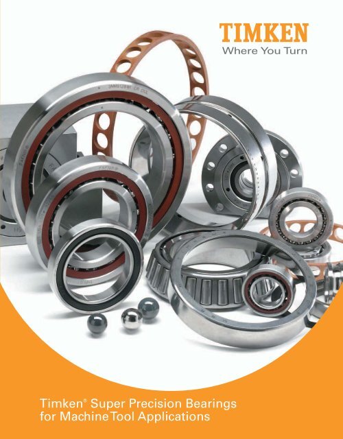
<strong>Timken</strong> ® <strong>Super</strong> <strong>Precision</strong> <strong>Bearings</strong><br />
<strong>for</strong> <strong>Machine</strong> <strong>Tool</strong> <strong>Applications</strong>
A<br />
B<br />
C<br />
D<br />
INDEX<br />
ENGINEERING<br />
Bearing Selection Process . . . . . . . . . . . . . . . . . . . . . . . . . . . . . . . . . . . . . . . . 13<br />
Determination of Applied Loads and Bearing Analysis . . . . . . . . . . . . . . . 36<br />
Bearing Reactions, Load Ratings and Life . . . . . . . . . . . . . . . . . . . . . . . . . . 42<br />
Permissible Operating Speed . . . . . . . . . . . . . . . . . . . . . . . . . . . . . . . . . . . . . 53<br />
Lubrication . . . . . . . . . . . . . . . . . . . . . . . . . . . . . . . . . . . . . . . . . . . . . . . . . . . . . . 56<br />
Run-In Procedures . . . . . . . . . . . . . . . . . . . . . . . . . . . . . . . . . . . . . . . . . . . . . . . 61<br />
Heat Generation and Dissipation . . . . . . . . . . . . . . . . . . . . . . . . . . . . . . . . . . . 64<br />
Tolerances . . . . . . . . . . . . . . . . . . . . . . . . . . . . . . . . . . . . . . . . . . . . . . . . . . . . . . 67<br />
Fitting Practices . . . . . . . . . . . . . . . . . . . . . . . . . . . . . . . . . . . . . . . . . . . . . . . . . 80<br />
Shaft and Housing Considerations . . . . . . . . . . . . . . . . . . . . . . . . . . . . . . . . . 88<br />
Mounting Designs . . . . . . . . . . . . . . . . . . . . . . . . . . . . . . . . . . . . . . . . . . . . . . . . 92<br />
Setting and Preloading Guidelines . . . . . . . . . . . . . . . . . . . . . . . . . . . . . . . . 101<br />
PRECISION TAPERED ROLLER BEARINGS<br />
Part Numbering Systems . . . . . . . . . . . . . . . . . . . . . . . . . . . . . . . . . . . . . . . . . 107<br />
Introduction . . . . . . . . . . . . . . . . . . . . . . . . . . . . . . . . . . . . . . . . . . . . . . . . . . . . 110<br />
TS Style – Metric, Inch . . . . . . . . . . . . . . . . . . . . . . . . . . . . . . . . . . . . . . . . . . 112<br />
TSF Style – Metric, Inch . . . . . . . . . . . . . . . . . . . . . . . . . . . . . . . . . . . . . . . . . 116<br />
TXR Style – Metric, Inch . . . . . . . . . . . . . . . . . . . . . . . . . . . . . . . . . . . . . . . . . 120<br />
TSHR Style – Metric, Inch . . . . . . . . . . . . . . . . . . . . . . . . . . . . . . . . . . . . . . . . 122<br />
SUPER PRECISION BALL BEARINGS<br />
Introduction . . . . . . . . . . . . . . . . . . . . . . . . . . . . . . . . . . . . . . . . . . . . . . . . . . . . 134<br />
Optimized Grades of <strong>Precision</strong> . . . . . . . . . . . . . . . . . . . . . . . . . . . . . . . . . . . . 134<br />
Bearing Types . . . . . . . . . . . . . . . . . . . . . . . . . . . . . . . . . . . . . . . . . . . . . . . . . . 134<br />
<strong>Applications</strong> . . . . . . . . . . . . . . . . . . . . . . . . . . . . . . . . . . . . . . . . . . . . . . . . . . . . 137<br />
Spindle <strong>Bearings</strong> . . . . . . . . . . . . . . . . . . . . . . . . . . . . . . . . . . . . . . . . . . . . . . . . 142<br />
Ball Screw Support <strong>Bearings</strong> . . . . . . . . . . . . . . . . . . . . . . . . . . . . . . . . . . . . 200<br />
Ex-Cell-O Spindle <strong>Bearings</strong> . . . . . . . . . . . . . . . . . . . . . . . . . . . . . . . . . . . . . . 214<br />
APPENDIX<br />
Frequency Coefficients . . . . . . . . . . . . . . . . . . . . . . . . . . . . . . . . . . . . . . . . . . 218<br />
Tapered Roller <strong>Bearings</strong> . . . . . . . . . . . . . . . . . . . . . . . . . . . . . . . . . . . . . . . 218<br />
Ball <strong>Bearings</strong> . . . . . . . . . . . . . . . . . . . . . . . . . . . . . . . . . . . . . . . . . . . . . . . . . 222<br />
Ball Screw Support Series . . . . . . . . . . . . . . . . . . . . . . . . . . . . . . . . . . . . . 236<br />
<strong>Precision</strong> Tag Deviation and Runout Charts . . . . . . . . . . . . . . . . . . . . . . . . 237<br />
Geometry Factors . . . . . . . . . . . . . . . . . . . . . . . . . . . . . . . . . . . . . . . . . . . . . . . 239<br />
Radial Internal Clearance . . . . . . . . . . . . . . . . . . . . . . . . . . . . . . . . . . . . . . . . 241<br />
Bearing Locknuts . . . . . . . . . . . . . . . . . . . . . . . . . . . . . . . . . . . . . . . . . . . . . . . 242<br />
Locknut Torque . . . . . . . . . . . . . . . . . . . . . . . . . . . . . . . . . . . . . . . . . . . . . . . . . 242<br />
Lubrication Specifications . . . . . . . . . . . . . . . . . . . . . . . . . . . . . . . . . . . . . . . 243<br />
Operating Temperatures <strong>for</strong> Bearing Component Materials . . . . . . . . . . 245<br />
Conversion Tables . . . . . . . . . . . . . . . . . . . . . . . . . . . . . . . . . . . . . . . . . . . . . . . 246<br />
Forms . . . . . . . . . . . . . . . . . . . . . . . . . . . . . . . . . . . . . . . . . . . . . . . . . . . . . . . . . . 247<br />
2<br />
2<br />
2<br />
TIMKEN PRODUCTS CATALOG 1<br />
• • •
TIMKEN MACHINE TOOL CATALOG<br />
TIMKEN. WHERE YOU TURN.<br />
The world turns to <strong>Timken</strong> <strong>for</strong> innovation to move ahead of the<br />
competition. Our contributions to advancing work and living<br />
standards – through innovations surrounding friction management<br />
and power transmission – are invaluable. We have played a role<br />
in virtually all major technologies that have shaped our age, from<br />
automobile travel to artificial hearts. You’ll find our products<br />
wherever you turn – on land, sea and in space.<br />
When customers turn to us, they are turning to a worldwide team of<br />
highly trained and experienced associates. Because of our ability to<br />
help their products per<strong>for</strong>m better, customers honor us with more<br />
than 300 awards each year. Whether it is a wheel assembly <strong>for</strong> a<br />
family vehicle, bearings <strong>for</strong> a roller coaster, repair services <strong>for</strong> rail<br />
bearings or steel <strong>for</strong> an aircraft engine shaft, we supply the products<br />
and services that help keep the world turning.<br />
FRICTION MANAGEMENT SOLUTIONS –<br />
A TOTAL SYSTEM APPROACH<br />
2<br />
2<br />
As needs change and advanced motion control systems evolve,<br />
<strong>Timken</strong> is leveraging its knowledge of friction management to offer a<br />
broader array of bearings, related products and integrated services<br />
to the marketplace. We supply quality products and services that<br />
extend beyond bearings to help all systems run smoothly.<br />
We are committed to providing a wide array of friction management<br />
solutions. Customers can benefit by having <strong>Timken</strong>, a trusted name<br />
<strong>for</strong> more than 100 years, evaluate entire systems, not just individual<br />
components. This approach provides cost-effective solutions, while<br />
also helping to achieve application-specific objectives.<br />
2<br />
2 TIMKEN MACHINE TOOL CATALOG
Introduction<br />
TECHNOLOGY THAT MOVES YOU<br />
Today, major industries turn to <strong>Timken</strong> <strong>for</strong> our ability to influence the<br />
fundamentals of motion through the creation, transfer, and control<br />
of power. We invest in people, attracting scholars, engineers and<br />
specialists from around the world. We invest in tools – computers,<br />
manufacturing equipment and state-of-the-art laboratories. We<br />
invest in the future by identifying new concepts that will help <strong>Timken</strong><br />
and its customers make their mark <strong>for</strong> years to come. Innovation is<br />
one of our core values.<br />
The return on our technology investment has grown exponentially.<br />
Our associates increase the reliability of <strong>Timken</strong> ® products and<br />
create designs that can set new per<strong>for</strong>mance standards. We help<br />
customers solve their immediate system issues, while developing<br />
the systems of tomorrow.<br />
Our teams of engineers and scientists are dedicated to using<br />
everything they know about friction management and power<br />
transmission. They translate the scientific aspects of metallurgy,<br />
bearing operating characteristics, lubrication, torque, noise,<br />
heat treatment, advanced processing concepts and application<br />
development into friction management solutions.<br />
Because our teams are located at technology centers in North<br />
America, Europe and Asia – as well as in our manufacturing<br />
facilities and field offices on six continents – customers have<br />
access to ideas and resources to trans<strong>for</strong>m concepts<br />
into reality. Our technology focuses on products,<br />
materials, processes and emerging technology to<br />
create new solutions.<br />
TIMKEN MACHINE TOOL CATALOG 3
TIMKEN MACHINE TOOL CATALOG<br />
BRANDS YOU CAN TRUST<br />
<strong>Timken</strong> has built a strong tradition of quality,<br />
technology and innovation. A long list of customer<br />
certifications provides solid evidence that our<br />
products have earned customer trust. As our<br />
founder, Henry <strong>Timken</strong>, said, “Don’t set your<br />
name to anything you will ever have cause to be<br />
ashamed of.”<br />
From design to distribution, <strong>Timken</strong> gives<br />
customers expanded options and the security of<br />
knowing that each box contains an industry-trusted<br />
product.<br />
ABOUT THE TIMKEN COMPANY<br />
2<br />
The <strong>Timken</strong> Company is a diversified industrial manufacturer of<br />
innovative, highly<br />
engineered materials, products and power<br />
transmission systems. <strong>Timken</strong>'s proprietary technologies reduce<br />
friction and enable machinery to operate more efficiently, powerfully<br />
and reliably, using less energy. With operations throughout the<br />
world, the company serves a wide range of mobile, industrial and<br />
aerospace customers<br />
<strong>Timken</strong> has technical centers in North America, Europe and Asia<br />
and more than 100 years of engineering experience. Recognized<br />
by Forbes magazine in 2009 as one of the “100 Most Trustworthy<br />
Companies in America,” <strong>Timken</strong> has been listed on the New York<br />
Stock Exchange since 1922.<br />
2<br />
2<br />
4 TIMKEN MACHINE TOOL CATALOG
Introduction<br />
TIMKEN MACHINE TOOL SOLUTIONS<br />
When it comes to improving machine tool per<strong>for</strong>mance, <strong>Timken</strong> leads<br />
the industry with an unmatched offering of friction management<br />
solutions. Our roller bearings and related products and services set<br />
the standard in high-speed spindles, ball screws, rotary tables and<br />
other demanding applications. This wide variety means that we can<br />
offer the right bearing <strong>for</strong> almost any machine position.<br />
Backed by global <strong>Timken</strong> innovation and a long machine tool<br />
heritage, we focus on enhancing customer per<strong>for</strong>mance and<br />
productivity through our product technology and application<br />
experience. With renowned <strong>Timken</strong> quality and a commitment to<br />
precision that exceeds industry standards, we continue to develop<br />
bearings that support the drive <strong>for</strong> higher speeds, maximum<br />
resolution, accuracy and repeatability. Longer bearing service life<br />
translates to more machine uptime and production throughput.<br />
PRODUCT BREADTH<br />
<strong>Timken</strong> offers a broad range of rolling bearings and related<br />
products and services to meet worldwide machine tool<br />
needs. Our portfolio includes specialized tapered ed roller<br />
and ball bearings, produced to the precision classes<br />
that deliver the operating characteristics necessary<br />
<strong>for</strong> the highest per<strong>for</strong>mance. <strong>Timken</strong> ® bearings<br />
meet or exceed application needs <strong>for</strong> rotational<br />
accuracy, consistency and rigidity. Our total<br />
friction management approach also includes<br />
lubrication, condition monitors and other<br />
products “around the bearing.”<br />
<strong>Timken</strong> ® tapered roller bearing types available in precision classes<br />
include the single-row TS and TSF styles, as well as the variablepreload<br />
Hydra-Rib bearing, the high-speed TSMA bearing and<br />
the compact TXR crossed roller bearing. <strong>Timken</strong> ® precision tapered<br />
roller bearings range from less than 20.000 mm (0.7874 in.) bore to<br />
more than 2000.000 mm (78.7402 in.) outside diameter, depending<br />
upon bearing type.<br />
<strong>Timken</strong> ® Fafnir ® angular contact ball bearings are manufactured<br />
to ABEC 7 (ISO P4) and ABEC 9 (ISO P2) precision classes. They<br />
are available in 15 degree and 25 degree contact angles, as well<br />
as custom configurations. Different ring designs (WI, WO, WN<br />
and K) meet specific application requirements with either steel or<br />
ceramic balls. The HX and sealed HXVV bearings deliver high-speed<br />
benefits with unique ball complements and raceway geometries.<br />
Sizes range from 10.000 mm (0.3937 in.) bore to 400.000 mm (15.7480<br />
in.) outside diameter.<br />
Ball screw support bearings with steep contact angles, available<br />
singly, or in housed units, provide high levels of stiffness <strong>for</strong> the<br />
demands of servo-controlled machinery. Sealed<br />
double-row flanged (or cartridge)<br />
units simplify installation.<br />
TIMKEN MACHINE TOOL CATALOG 5
TIMKEN MACHINE TOOL CATALOG<br />
The Quick Change Program can per<strong>for</strong>m cost-effective<br />
modifications and minor rework procedures to your machine<br />
tool bearings to extend operational and application<br />
flexibility.<br />
Engineered Surfaces improve wear and fatigue resistance<br />
<strong>for</strong> bearings and other components through a variety of<br />
applied treatments and finishes.<br />
Condition Monitoring Products and Services are available<br />
in an expanding offering that enables you to stay on top of<br />
machine per<strong>for</strong>mance, and quickly<br />
detect potential problems.<br />
2<br />
2<br />
As a <strong>Timken</strong> customer, you receive an uncompromising standard of<br />
quality across the broadest range of bearings and related products.<br />
Brands like <strong>Timken</strong> and Fafnir reflect an extensive line of tapered,<br />
spherical, cylindrical, ball bearings and mounted units ideal <strong>for</strong><br />
virtually every machine tool and industrial application. Our core<br />
products are complemented by an ever-growing<br />
line of friction management solutions including<br />
lubricants, single-point lubricators, maintenance<br />
tools, safety equipment, condition monitoring<br />
systems and repair services that help keep<br />
operations running smoothly.<br />
Ultra-High Speed Spindle Grease, part of <strong>Timken</strong>’s<br />
broad lubricant line, is specifically designed <strong>for</strong> the<br />
precision and high-speed bearings typically used<br />
in machine tools.<br />
2<br />
6 TIMKEN MACHINE TOOL CATALOG
Introduction<br />
ABOUT THIS CATALOG<br />
<strong>Timken</strong> offers an extensive range of bearings and accessories in<br />
both imperial and metric sizes. For your convenience, size ranges<br />
are indicated both in millimeters and inches. Contact your <strong>Timken</strong><br />
sales representative to learn more about our complete line <strong>for</strong> the<br />
special needs of your application.<br />
USING THIS CATALOG<br />
We are committed to providing our customers with maximum<br />
service and quality. This catalog contains dimensions, tolerances<br />
and load ratings, as well as an engineering section describing fitting<br />
practices <strong>for</strong> shafts and housings, internal clearances, materials,<br />
and other bearing features. It can provide valuable assistance in the<br />
initial consideration of the type and characteristics of the bearing<br />
that may best suit your particular needs.<br />
CATALOG FEATURES<br />
Dimension and load rating data within the various types and styles<br />
of bearings is organized by size.<br />
ISO, DIN, and ABMA, as used in this catalog, refer to the International<br />
Organization <strong>for</strong> Standardization, Deutsches Institut für Normung EV<br />
and the American Bearing Manufacturers Association.<br />
SPECIAL APPLICATIONS<br />
Some products, such as <strong>for</strong> aerospace applications, are made to<br />
special standards, and only the original equipment manufacturer<br />
can determine if a particular bearing is suitable <strong>for</strong> use in their<br />
equipment.<br />
NOTE<br />
Product per<strong>for</strong>mance is affected by many factors beyond the control<br />
of <strong>Timken</strong>. There<strong>for</strong>e, the suitability and feasibility of all designs<br />
and product selection should be validated by you. This catalog is<br />
provided solely to give you, a customer of <strong>Timken</strong> or its parent or<br />
affiliates, analysis tools and data to assist you in your design.<br />
No warranty, expressed or implied, including any warranty of<br />
merchantability or fitness <strong>for</strong> a particular purpose, is made by<br />
<strong>Timken</strong>. <strong>Timken</strong> products are sold subject to a Limited Warranty.<br />
TIMKEN MACHINE TOOL CATALOG 7
TIMKEN MACHINE TOOL CATALOG<br />
2<br />
2<br />
2<br />
LIMITED WARRANTY<br />
We warrant <strong>for</strong> a period of one year (unless a shorter period applies<br />
to a particular product) from the date of shipment that our products<br />
shall be free of defects in material and workmanship, as shall be<br />
determined by our manufacturing standards, and shall con<strong>for</strong>m to<br />
the description on the face of our quotation or this acknowledgment.<br />
THE WARRANTY DESCRIBED HEREIN SHALL BE IN LIEU OF ANY<br />
OTHER WARRANTY, EXPRESS OR IMPLIED, INCLUDING BUT NOT<br />
LIMITED TO ANY IMPLIED WARRANTY OF MERCHANTABILITY OR<br />
FITNESS FOR A PARTICULAR PURPOSE. The terms contained herein<br />
constitute the entire agreement of the parties and the warranty<br />
representations of the seller. There are no other representations,<br />
warranties, or guarantees applicable to the sale of our products<br />
unless otherwise expressly agreed to by us in writing.<br />
PURCHASER’S EXCLUSIVE REMEDY/<br />
SELLER’S EXPRESS LIMIT OF LIABILITY<br />
Purchaser’s exclusive remedy <strong>for</strong> any warranty<br />
claim, or <strong>for</strong> any claim arising out of the<br />
purchase or use of our products, shall be<br />
the replacement of said products. We will<br />
replace our products, without charge to the<br />
purchaser, f.o.b. our point of shipment. We will<br />
not be liable <strong>for</strong> any consequential, incidental,<br />
or other damages sustained by purchaser,<br />
including but not limited to, loss of profits or<br />
revenue, loss of use of product, cost of capital, cost<br />
of substituted product, facilities, services, or claims of<br />
purchaser’s customers <strong>for</strong> any damages. Any warranty<br />
claim of purchaser must be made within one year of the<br />
date of shipment of the product. This exclusive remedy applies<br />
regardless of the nature of purchaser’s claim, whether in contract,<br />
tort, express or implied warranty, negligence or strict liability, upon<br />
which damages are claimed and regardless of whether the same is<br />
due to our negligence or any defect in our product.<br />
TERMS AND CONDITIONS OF SALE<br />
All products described in this catalog are sold subject to <strong>Timken</strong>’s<br />
Terms and Conditions of Sale.<br />
It is understood that the buyer, in selecting and ordering from this<br />
catalog, which supersedes all previous editions, accepts all Terms<br />
and Conditions of Sale, a copy of which may be obtained from your<br />
<strong>Timken</strong> sales office. <strong>Timken</strong> objects to any additional or different<br />
terms.<br />
WARNING<br />
Failure to observe the following warnings could<br />
create a risk of serious injury.<br />
Proper maintenance and handling practices are critical.<br />
Always follow installation instructions and<br />
maintain proper lubrication.<br />
Never spin a bearing with compressed air.<br />
The rolling elements may be <strong>for</strong>cefully expelled.<br />
8 TIMKEN MACHINE TOOL CATALOG<br />
NOTE<br />
Every reasonable ef<strong>for</strong>t has been made to ensure the accuracy<br />
of the in<strong>for</strong>mation contained in this catalog, but no liability is<br />
accepted <strong>for</strong> errors, omissions or <strong>for</strong> any other reason.
Introduction<br />
SHELF LIFE AND STORAGE OF<br />
GREASE-LUBRICATED BEARINGS AND<br />
COMPONENTS<br />
<strong>Timken</strong> guidelines <strong>for</strong> the shelf life of grease-lubricated rolling<br />
bearings, components and assemblies are set <strong>for</strong>th below. Shelf<br />
life in<strong>for</strong>mation is based on test data and experience. Shelf life<br />
should be distinguished from lubricated bearing/component service<br />
life as follows:<br />
SHELF LIFE<br />
Shelf life of the grease-lubricated bearing/component represents<br />
the period of time prior to use or installation. The shelf life is a portion<br />
of the anticipated aggregate service life.<br />
It is impossible to accurately predict service life due to variations in<br />
lubricant bleed rates, oil migration, operating conditions, installation<br />
conditions, temperature, humidity and extended storage. <strong>Timken</strong><br />
cannot anticipate the per<strong>for</strong>mance of the grease lubricant after the<br />
bearing or component is installed or placed in service.<br />
The bearing shelf life is related primarily to the lubricant’s ability<br />
to maintain the bearing’s original manufactured radial internal<br />
clearance and freedom to rotate.<br />
The component shelf life is related to the ability of the component<br />
to function as originally intended.<br />
Shelf life values, available from <strong>Timken</strong>, represent a maximum<br />
limit and assume adherence to the <strong>Timken</strong> suggested storage and<br />
handling guidelines. Deviations from <strong>Timken</strong>’s storage and handling<br />
guidelines may reduce shelf life. Any specification or operating<br />
practice that defines a shorter shelf life should be used.<br />
TIMKEN DISCLAIMS RESPONSIBILITY FOR THE SHELF LIFE OF ANY<br />
BEARING/COMPONENT LUBRICATED BY ANOTHER PARTY.<br />
STORAGE<br />
<strong>Timken</strong> suggests the following storage guidelines <strong>for</strong> its finished<br />
products (bearings, components, and assemblies, hereinafter<br />
referred to as “Products”):<br />
• Unless directed otherwise by <strong>Timken</strong>, Products should be kept<br />
in their original packaging until they are ready to be placed<br />
into service.<br />
• Do not remove or alter any labels or stencil markings on the<br />
packaging.<br />
• Products should be stored in such a way that the packaging is<br />
not pierced, crushed or otherwise damaged.<br />
• After a Product is removed from its packaging, it should be<br />
placed into service as soon as possible.<br />
• When removing a Product that is not individually packaged<br />
from a bulk pack container, the container should be resealed<br />
immediately after the Product is removed.<br />
• Do not use Product that has exceeded its shelf life as defined<br />
in <strong>Timken</strong>’s shelf life guidelines statement.<br />
• The storage area temperature should be maintained between<br />
0º C (32º F) and 40º C (104º F); temperature fluctuations should<br />
be minimized.<br />
• The relative humidity should be maintained below 60 percent.<br />
• The storage area should be kept free from airborne<br />
contaminants such as, but not limited to: dust, dirt, harmful<br />
vapors, etc.<br />
• The storage area should be isolated from undue vibration.<br />
• Extreme conditions of any kind should be avoided.<br />
TIMKEN MACHINE TOOL CATALOG 9
TIMKEN MACHINE TOOL CATALOG<br />
Inasmuch as <strong>Timken</strong> is not familiar with a customer’s particular<br />
storage conditions, these guidelines are strongly suggested.<br />
However, the customer may very well be required by circumstance<br />
or applicable government requirements to adhere to stricter storage<br />
requirements.<br />
Most bearing types are typically shipped protected with a corrosionpreventive<br />
compound that is not a lubricant. Such bearings may<br />
be used in oil-lubricated applications without removal of the<br />
corrosion-preventive compound. When using some specialized<br />
grease lubrication it is advisable to remove the corrosion-preventive<br />
compound be<strong>for</strong>e packing the bearings with suitable grease.<br />
Some bearing types in this catalog are pre-packed with generalpurpose<br />
grease suitable <strong>for</strong> their normal application. Frequent<br />
replenishment of the grease may be necessary <strong>for</strong> optimum<br />
per<strong>for</strong>mance. Care must be exercised in lubricant selection,<br />
however, since different lubricants are often incompatible.<br />
When specified by the customer, bearings may be ordered prelubricated<br />
with suitable greases and oils.<br />
Upon receipt of a bearing shipment, it should be ensured that the<br />
bearings are not removed from their packaging until they are ready<br />
<strong>for</strong> mounting so that they do not become corroded or contaminated.<br />
<strong>Bearings</strong> should be stored in an appropriate atmosphere in order<br />
that they remain protected <strong>for</strong> the intended period.<br />
Any questions concerning the shelf life or storage policy should be<br />
directed to your local sales office.<br />
2<br />
2<br />
2<br />
10 TIMKEN MACHINE TOOL CATALOG
Bearing Selection<br />
A<br />
ENGINEERING<br />
A<br />
A<br />
ENGINEERING<br />
Bearing Selection Process . . . . . . . . . . . . . . . . . . . . . . . . . . . . 13<br />
Determination of Applied Loads and Bearing Analysis . . . . 36<br />
Bearing Reactions, Load Ratings and Life . . . . . . . . . . . . . . . 42<br />
Permissible Operating Speed . . . . . . . . . . . . . . . . . . . . . . . . . . 53<br />
Lubrication . . . . . . . . . . . . . . . . . . . . . . . . . . . . . . . . . . . . . . . . . . 56<br />
Run-In Procedures. . . . . . . . . . . . . . . . . . . . . . . . . . . . . . . . . . . . 61<br />
Heat Generation and Dissipation . . . . . . . . . . . . . . . . . . . . . . . 64<br />
Tolerances . . . . . . . . . . . . . . . . . . . . . . . . . . . . . . . . . . . . . . . . . . 67<br />
Fitting Practices. . . . . . . . . . . . . . . . . . . . . . . . . . . . . . . . . . . . . . 80<br />
Shaft and Housing Considerations . . . . . . . . . . . . . . . . . . . . . . 88<br />
Mounting Designs . . . . . . . . . . . . . . . . . . . . . . . . . . . . . . . . . . . . 92<br />
Setting and Preloading Guidelines . . . . . . . . . . . . . . . . . . . . 101<br />
TIMKEN MACHINE TOOL CATALOG 11 TIMKEN MACHINE TOOL CATALOG 11
A<br />
ENGINEERING<br />
A<br />
12 TIMKEN MACHINE TOOL CATALOG
THE BEARING SELECTION PROCESS<br />
TIMKEN ® BEARINGS<br />
<strong>Timken</strong> provides an extensive variety of rolling bearing types and<br />
sizes – to the extent that customers need not look elsewhere.<br />
Knowing that the bearing is often the most critical component within<br />
a moving assembly, <strong>Timken</strong> engineers take great care to ensure the<br />
customer is receiving maximum value when a <strong>Timken</strong> ® bearing is<br />
selected to per<strong>for</strong>m a given function. With the acquisition of the<br />
Fafnir ® brand, <strong>Timken</strong> can provide the proper bearing <strong>for</strong> virtually<br />
any motion-control application. With more than a century of proven<br />
experience in bearing technology, <strong>Timken</strong> is truly a world leader in<br />
the rolling bearing industry.<br />
ENGINEERING<br />
• Higher technical demands or higher levels of application<br />
requirements.<br />
• Higher levels of machine complexity.<br />
• Critical applications where system damage must be avoided<br />
<strong>for</strong> all modes of operation.<br />
• Potential exposure to personal injury.<br />
• Costly damage or downtime resulting from the use of an<br />
inappropriate bearing <strong>for</strong> a given task.<br />
A<br />
The <strong>Timken</strong> Company has an experienced, highly skilled staff of<br />
trained engineers located around the world to assist the customer<br />
in bringing new, mechanized products to market. <strong>Timken</strong> engineers<br />
are a powerful resource <strong>for</strong> customers to turn to <strong>for</strong> assistance in<br />
the appropriate selection of bearings to meet any of the following<br />
considerations:<br />
Because <strong>Timken</strong> offers so many bearing configurations to serve a<br />
wide variety of situations, a suggested starting point in the selection<br />
process should focus on the assessment of two basic categories:<br />
the first being boundary (or fixed) conditions and the second being<br />
per<strong>for</strong>mance expectations (or desired results). Depending on your<br />
application, the boundary conditions and per<strong>for</strong>mance expectations<br />
will vary. Trade-offs or compromises must often be addressed so that<br />
the final bearing type and size selected are a reasonable balance<br />
of all factors. It is a wise practice to examine factors critical to the<br />
success of the device and prioritize them.<br />
TIMKEN MACHINE TOOL CATALOG 13
ENGINEERING<br />
A<br />
Typical considerations in machine design also include optimization<br />
of controllable variables affecting application per<strong>for</strong>mance:<br />
• Bearing design.<br />
• Bearing shaft and housing arrangement; shaft and housing<br />
material.<br />
• Installation and handling requirements of the bearing, as well<br />
as shaft and housing preparation.<br />
• Presence of adequate sealing <strong>for</strong> the exclusion of<br />
contaminants; types of <strong>for</strong>eign materials possible.<br />
• Lubricating method (lubrication type and delivery system).<br />
• Maintenance procedures and intervals.<br />
Boundary (or fixed) conditions that should be taken into consideration<br />
include:<br />
• External loads, including radial, thrust, moment, shock and<br />
combination loads.<br />
• Acceleration and deceleration levels.<br />
• Operating temperature range (including extreme limits and<br />
thermal cycling).<br />
• Other environmental factors, such as humidity, fluids,<br />
vibration, debris, magnetic fields.<br />
• Spatial constraints.<br />
Per<strong>for</strong>mance expectations (or desired results) to consider<br />
include:<br />
• Rotational accuracy and repeatability (e.g., service precision<br />
level).<br />
• System rigidity (axial or radial stiffness).<br />
• Application service life.<br />
• Speed.<br />
Since the rolling bearing is an integral part of the machine, looking<br />
at the key operating parameters of the system also will help focus<br />
on the most viable bearing solution.<br />
Once these conditions and expectations have been identified and<br />
prioritized, the most appropriate bearing type(s), size(s), and part<br />
number(s) that meet the basic application requirements can be<br />
selected.<br />
BEARING PERFORMANCE CHARACTERISTICS<br />
The following matrix should be viewed only as a general overview<br />
of bearings available from <strong>Timken</strong> and their general per<strong>for</strong>mance<br />
characteristics. Bearing selection is not a clear-cut, simplistic<br />
procedure, but rather a sequence of interdependent tasks that must<br />
take into consideration customer goals, manufacturing economics,<br />
design expectations and, above all, human safety.<br />
Most machine tool applications require bearings with extreme<br />
precision, designed specifically to meet the boundary conditions<br />
and per<strong>for</strong>mance requirements. <strong>Timken</strong> ® super precision bearings<br />
offer quality and precision tolerances to help customers achieve<br />
target job requirements and production throughput. It is always<br />
prudent to enlist the assistance of your <strong>Timken</strong> representative to<br />
achieve optimum results.<br />
14 TIMKEN MACHINE TOOL CATALOG
ENGINEERING<br />
A<br />
Tapered roller bearing<br />
Thrust tapered roller bearing<br />
Cylindrical roller bearing<br />
Thrust cylindrical roller bearing<br />
Spherical roller bearing<br />
Thrust spherical roller bearing<br />
Ball bearing<br />
Thrust ball bearing<br />
Needle roller bearing<br />
Thrust needle roller bearing<br />
Characteristic<br />
Tapered roller<br />
bearing<br />
Thrust tapered<br />
roller bearing<br />
Cylindrical roller<br />
bearing<br />
Thrust cylindrical<br />
roller bearing<br />
Spherical roller<br />
bearing<br />
Thrust spherical<br />
roller bearing<br />
Ball bearing<br />
Thrust ball<br />
bearing<br />
Needle roller<br />
bearing<br />
Thrust needle<br />
roller bearing<br />
Pure radial<br />
load<br />
Excellent Unsuitable Excellent Unsuitable Excellent Unsuitable Good Poor Excellent Unsuitable<br />
Pure axial load Good Excellent Unsuitable Good Fair Excellent Fair Excellent Unsuitable Excellent<br />
Combined load Excellent Fair Fair Unsuitable Excellent Fair Good Poor Unsuitable Unsuitable<br />
Moment load Fair Poor Unsuitable Unsuitable Unsuitable Unsuitable Good Poor Fair Unsuitable<br />
High stiffness Excellent Excellent Good Excellent Good Good Fair Good Good Excellent<br />
Quiet running Fair Fair Good Poor Fair Poor Excellent Good Good Fair<br />
Low friction Fair Fair Good Poor Fair Fair Excellent Excellent Good Good<br />
Misalignment Poor Poor Poor Unsuitable Excellent Excellent Good Poor Poor Poor<br />
Locating<br />
position<br />
(fixed)<br />
Non-locating<br />
position<br />
(floating)<br />
Excellent Good Fair Fair Good Good Good Excellent Unsuitable Excellent<br />
Good Unsuitable Excellent Unsuitable Fair Unsuitable Good Unsuitable Good Unsuitable<br />
Speed Good Good Good Poor Fair Fair Excellent Excellent Good Poor<br />
Table 1. Relative operating characteristics of various bearing types.<br />
TIMKEN MACHINE TOOL CATALOG 15
A<br />
ENGINEERING<br />
TIMKEN ® SUPER PRECISION BEARINGS<br />
Manufacturers require machine tools that are extremely accurate,<br />
reliable and capable of high levels of productivity. A major<br />
contribution to the per<strong>for</strong>mance of any machine tool is supplied by<br />
the rolling bearings used to support the spindles, rotating tables,<br />
ball screws and other critical precision positions. A manufactured<br />
bearing’s precision level has a major influence on the ability to<br />
per<strong>for</strong>m in high-speed applications commonly seen in factory<br />
machining environments.<br />
WHICH TYPE OF TIMKEN BEARING IS MOST<br />
APPROPRIATE FOR YOUR MACHINE TOOL<br />
APPLICATION?<br />
To achieve the highest possible per<strong>for</strong>mance precision level, the<br />
majority of machine tool-related bearing applications must address<br />
four primary requirements: speed, stiffness, accuracy and load<br />
capacity.<br />
Speed<br />
Today’s industrial machining environments stress maximum<br />
production rates. To reach these high metal-removal goals,<br />
machines are operating at maximum speeds with working spindles<br />
tuned to provide premium running accuracy.<br />
Achievable spindle rotating speeds require management of heat<br />
generation within the bearing assembly. The bearing’s ability to not<br />
only minimize heat buildup, but also expel excess heat, is a crucial<br />
consideration in the bearing selection process. Because of the<br />
differences in rolling element contact geometry, ball bearings are<br />
superior in minimizing heat generation, especially where higher<br />
speeds are desired.<br />
Max Speed (RPM)<br />
14000<br />
12000<br />
10000<br />
8000<br />
6000<br />
4000<br />
2000<br />
Tapered Roller Bearing (TS Metric)<br />
Ball Bearing (2MM9100WI)<br />
0<br />
70 100 130 160<br />
Bore (mm)<br />
Fig. 1. Tapered roller bearing vs. ball bearing maximum permissible<br />
speed (with synthetic high-speed grease).<br />
<strong>Timken</strong> offers a wide range of<br />
products targeted <strong>for</strong> improving<br />
machining efficiency, cutting<br />
accuracy, and productivity.<br />
Qualified sales and service<br />
engineers are available to help<br />
determine an appropriate solution<br />
<strong>for</strong> individual applications.<br />
Figure 1 compares the relative maximum speed of similar cross<br />
section ball and tapered roller bearings (both using synthetic<br />
grease as a baseline lubricant). There<strong>for</strong>e, in applications where<br />
higher RPM levels are the primary concern, ball bearings have a<br />
distinct advantage.<br />
<strong>Bearings</strong> must be carefully designed to minimize heat generation<br />
and vibration to enable high speeds. Specific strategies include<br />
overall bearing configuration, precision internal geometry<br />
and material selection. Optimizing bearing ring and shoulder<br />
construction with the ball complement supports higher speed<br />
per<strong>for</strong>mance. Engineering raceway and ball geometry helps to<br />
minimize friction, while ceramic rolling elements generate less heat<br />
with reduced skidding.<br />
To prevent vibration at high speeds, close bearing tolerances are<br />
required. <strong>Timken</strong> ® machine tool bearings are designed to meet or<br />
exceed industry tolerance standards and deliver smooth running<br />
per<strong>for</strong>mance.<br />
In addition to the use of hybrid ceramic technology, further<br />
enhancements in speed, as well as control of bearing noise and<br />
temperature, can be achieved through cage design or material,<br />
and choice of lubrication.<br />
16 TIMKEN MACHINE TOOL CATALOG
Many of the factors that allow <strong>for</strong> maximum speed have been<br />
designed into <strong>Timken</strong>’s HX series of super precision ball bearings.<br />
Engineered <strong>for</strong> the reduction of friction and minimum heat buildup,<br />
this series features unique ball complements and precisionengineered<br />
surface geometries. Options <strong>for</strong> further enhancing<br />
speed include the use of low weight ceramic rolling elements,<br />
lubrication designed <strong>for</strong> high speed, and lighter preload levels.<br />
These are discussed in further detail later in this catalog.<br />
Stiffness<br />
ENGINEERING<br />
The ability to minimize tool deflection experienced under cutting<br />
loads is vital to achieving the accuracy needed to produce finished<br />
parts within specified tolerances. Less variance produces better<br />
quality and helps keep product scrap levels at a minimum. <strong>Bearings</strong><br />
have a significant effect on spindle stiffness, due to their deflection<br />
under applied load. Because of their internal geometry and rolling<br />
element type, tapered roller bearings provide considerably higher<br />
stiffness levels as shown in Figure 3 and 4.<br />
A<br />
Outer ring<br />
Seals<br />
Inner ring<br />
Cage<br />
(retainer or<br />
separator)<br />
Balls<br />
Radial Stiffness (lbs./in.)<br />
18000000<br />
16000000<br />
14000000<br />
12000000<br />
10000000<br />
8000000<br />
6000000<br />
4000000<br />
2000000<br />
Tapered Roller Bearing (TS Metric)<br />
Ball Bearing (2MM9100WI)<br />
3000<br />
2000<br />
1000<br />
(N/mm)<br />
0<br />
70 100 130 160<br />
Bore (mm)<br />
0<br />
Cup (outer ring)<br />
Fig. 3. Tapered roller bearing vs. ball bearing radial stiffness.<br />
Cone<br />
(inner ring)<br />
Cage<br />
(retainer or<br />
separator)<br />
Tapered rollers<br />
Axial Stiffness (lbs./in.)<br />
4000000<br />
3500000<br />
3000000<br />
2500000<br />
2000000<br />
1500000<br />
1000000<br />
Tapered Roller Bearing (TS Metric)<br />
Ball Bearing (2MM9100WI)<br />
700<br />
600<br />
500<br />
400<br />
300<br />
200<br />
(N/mm)<br />
Fig. 2. Bearing components.<br />
500000<br />
100<br />
0<br />
70 100 130 160<br />
Bore (mm)<br />
Fig. 4. Tapered roller bearing vs. ball bearing axial stiffness.<br />
(1) For additional in<strong>for</strong>mation, see guidelines on page 101.<br />
Bearing stiffness also depends on design load zone, which is<br />
directly related to bearing setting, clearances and applied loads.<br />
(Setting is defined as a specific amount of either end play or<br />
preload.) (1) A bearing under radial load with zero end play/zero<br />
preload has a load zone close to 180 degrees, while a bearing<br />
with preload can reach 360 degrees load zone. Figure 5 shows the<br />
effect of load zone on tapered roller bearing stiffness. The curves<br />
demonstrate that while the effect of external loads on stiffness is<br />
important, the impact from setting is more significant.<br />
TIMKEN MACHINE TOOL CATALOG 17
A<br />
ENGINEERING<br />
Stiffness (relative to 180˚ load zone)<br />
2.5<br />
2<br />
1.5<br />
1<br />
0.5<br />
0<br />
Loading:<br />
100% C 90<br />
10% C 90<br />
45 90 135 180 225 270 315 360<br />
Load Zone (˚)<br />
Fig. 5. Effect of load zone on bearing stiffness.<br />
Since thermal expansion can dramatically affect preload or setting,<br />
it can also play a very important role in the resulting static and<br />
dynamic stiffness of a spindle system. This applies to ball bearings<br />
as well.<br />
An inherent advantage of the tapered roller bearing is that it can<br />
be adjusted after mounting. This means that the optimum stiffness<br />
can be obtained either by determining the proper setting during<br />
the mounting phase <strong>for</strong> a simple bearing arrangement, or during<br />
running by the use of a “variable preload” bearing design such as<br />
<strong>Timken</strong> ® Hydra-Rib TM and Spring-Rib TM bearings.<br />
To better manage the load sharing of the set of rolling elements,<br />
<strong>Timken</strong> offers a variety of designed-in preload levels <strong>for</strong> ball<br />
bearings. Be conservative with the addition of preloading as these<br />
<strong>for</strong>ces will contribute to heat generation, reducing the maximum<br />
permissible speed of either ball or tapered roller bearing designs.<br />
Accuracy<br />
Another key factor in the machine’s precision is the runout<br />
(rotational accuracy) of the bearing. This affects the geometry and<br />
surface finish of the target workpiece. For the ultimate accuracy<br />
and repeatability of machine tool motion, <strong>Timken</strong> ® super precision<br />
ball bearings offer the best control, with quietness of operation and<br />
reduced vibration. To achieve the highest level of precision with<br />
increased stiffness and load capacity, multiple ball bearings may<br />
be used in sets specifically designed <strong>for</strong> this purpose.<br />
The most widely recognized definition of quality is contained within<br />
the ABEC/ISO classes; however some factors affecting per<strong>for</strong>mance<br />
of a bearing are not completely defined within these standards. This<br />
allows <strong>for</strong> a significant range of variability in product per<strong>for</strong>mance<br />
among bearing manufacturers. To provide premium per<strong>for</strong>mance, all<br />
<strong>Timken</strong> ball bearing MM, MMV and MMX precision grades comply<br />
with strict controls over these non-specified parameters – all of<br />
which can have a direct impact on the service life and per<strong>for</strong>mance<br />
of a bearing.<br />
18 TIMKEN MACHINE TOOL CATALOG
ENGINEERING<br />
System bearing type<br />
Tapered roller bearings<br />
<strong>Timken</strong><br />
Crossed roller bearings<br />
C<br />
S<br />
<strong>Precision</strong> bearing class<br />
B<br />
A<br />
P<br />
–<br />
AA<br />
–<br />
A<br />
Metric<br />
Inch<br />
ISO/DIN All bearing types P5 P4 P2 –<br />
ABMA<br />
Non-tapered roller bearings<br />
Ball bearings<br />
Tapered roller bearings<br />
RBEC 5<br />
ABEC 5<br />
C<br />
RBEC 7<br />
ABEC 7<br />
B<br />
RBEC 9<br />
ABEC 9<br />
A<br />
–<br />
–<br />
–<br />
<strong>Timken</strong> Tapered roller bearings<br />
3<br />
0<br />
00<br />
000<br />
Crossed roller bearings<br />
3<br />
0<br />
–<br />
–<br />
Ball bearings ABEC 5 ABEC 7 ABEC 9 –<br />
ABMA Tapered roller bearings 3 0 00 –<br />
Table 2. <strong>Precision</strong> bearing classes.<br />
<strong>Super</strong> <strong>Precision</strong> Ball <strong>Bearings</strong>, <strong>Super</strong> High <strong>Precision</strong> (ABEC 7/9;<br />
ISO P4/P2)<br />
<strong>Timken</strong> super precision ball bearings manufactured to the MM/MMV<br />
tolerance class operate with running accuracy and per<strong>for</strong>mance<br />
levels meeting ABEC 9 (ISO P2) standards yet maintain other<br />
features at ABEC 7 (ISO P4) level <strong>for</strong> cost-effectiveness. Bore and<br />
O.D. surfaces are coded in micron units <strong>for</strong> the convenience of the<br />
discriminating machine tool builder striving <strong>for</strong> optimum fitting of<br />
crucial spindle components.<br />
Ultra-<strong>Precision</strong> Ball <strong>Bearings</strong> (ABEC 9, ISO P2)<br />
<strong>Timken</strong> MMX super precision ball bearings, with closer tolerances<br />
and running accuracies than ABEC 7 (ISO P4) bearings, are made to<br />
ABEC 9 (ISO P2) tolerances. <strong>Bearings</strong> produced to these tolerances<br />
are generally used on ultra-high-speed grinding spindles designed<br />
<strong>for</strong> tight dimensional tolerances and superfine surface finishes.<br />
Contact your <strong>Timken</strong> representative <strong>for</strong> availability of product<br />
range.<br />
<strong>Precision</strong> Tapered Roller <strong>Bearings</strong> (Class C/S/3,<br />
B/P/0 and A/00)<br />
The more demanding the precision objective, the more accurate<br />
the bearing must be. <strong>Timken</strong> provides three tapered roller bearing<br />
classes, in both metric and inch systems, that cover the full range of<br />
precision application requirements. In ascending order of accuracy,<br />
they are identified in the metric system as Class C/S, B/P, and A,<br />
while in the inch system as Class 3, 0, and 00.<br />
<strong>Precision</strong> Plus Tapered Roller <strong>Bearings</strong> (Class 000/AA)<br />
To further minimize the influence of variations, <strong>Timken</strong> offers a<br />
fourth level of precision tapered roller bearing manufacture so<br />
tightly controlled that it goes beyond the grade levels of both ISO<br />
and ABMA standards. <strong>Timken</strong>’s <strong>Precision</strong> Plus TM line offers (metricnominal)<br />
AA level and (inch-nominal) 000 tapered roller bearings in<br />
various sizes and styles.<br />
• High-speed motorized routers.<br />
• <strong>Precision</strong> milling/boring machines.<br />
• <strong>Super</strong> precision lathes.<br />
Class MM/MMV<br />
• <strong>Precision</strong> surface grinding machines.<br />
• Low precision machines.<br />
• Drilling machines.<br />
• Conventional lathes. Class C or 3<br />
• Milling machines.<br />
• <strong>Precision</strong> gear drives.<br />
• NC lathes.<br />
• Milling/boring machines. Class B or 0<br />
• Machining centers.<br />
• Ultra-precision grinding machines.<br />
• Ball screws.<br />
Class MMX<br />
• Grinding machines.<br />
• Jig boring machines.<br />
• Workpiece spindles Class A or 00<br />
(of cylindrical grinders).<br />
• High accuracy machines.<br />
• <strong>Precision</strong> measuring instruments. Class AA or 000<br />
• Special applications.<br />
<strong>Timken</strong> engineers have at<br />
their disposal vast resources<br />
of engineering data and<br />
application in<strong>for</strong>mation to<br />
select the right bearing<br />
class and tune the critical<br />
components so that the<br />
machine tool achieves its<br />
per<strong>for</strong>mance objectives.<br />
The adjacent table can be<br />
considered as a general<br />
guideline <strong>for</strong> common<br />
machine tool bearing<br />
applications.<br />
Table 3. Typical precision classes <strong>for</strong> common machine tool bearing applications.<br />
TIMKEN MACHINE TOOL CATALOG 19
A<br />
ENGINEERING<br />
Load Capacity<br />
Some machining centers, such as rough grinding operations, are<br />
strategically designed <strong>for</strong> higher material removal rates. The need<br />
<strong>for</strong> aggressive feed rates requires higher load-carrying capacities.<br />
These loads can be properly distributed among the rolling elements<br />
by providing a permanent <strong>for</strong>ce called “preload” or "setting." Preload<br />
is the strategic removal of radial play within the bearing to ensure<br />
proper rolling element contact on both the inner and outer race.<br />
While <strong>Timken</strong> posts its load capacities in the product tables within<br />
this catalog, many applications often approach only a fraction of<br />
those limits. For example, workpiece finish may determine the feed<br />
rates needed in an application, thereby decreasing the importance<br />
of bearing capacity.<br />
<strong>Timken</strong> can assist in the final bearing selection to help you achieve<br />
your precision machining production goals. <strong>Timken</strong>’s staff of<br />
application engineers is ready to put its vast experience to any<br />
test <strong>for</strong> assisting our customers with the challenging bearing<br />
applications commonly found in the machine tool industry. To refine<br />
your search, please turn to the sections covering tapered roller<br />
bearings (Sec. B) or ball bearings (Sec. C) <strong>for</strong> more in<strong>for</strong>mation<br />
needed to obtain a complete <strong>Timken</strong> part number specification.<br />
TIMKEN ® MACHINE TOOL BEARING<br />
DESIGN<br />
From this introductory discussion and the additional technical<br />
content within this catalog, one can obtain an indication of which<br />
rolling bearing type should be further investigated to meet the given<br />
set of boundary conditions and per<strong>for</strong>mance expectations.<br />
Static Load - Co (lbs.)<br />
Fig. 6. Effect of preloading on ball bearing raceway contact.<br />
Figure 7 compares the levels of static capacity of ball vs. tapered<br />
roller bearings <strong>for</strong> the benefit of contrasting basic load capability<br />
of both bearing types.<br />
Tapered Roller Bearing (TS Metric)<br />
90000 Ball Bearing (2MM9100WI)<br />
67500<br />
45000<br />
22500<br />
0<br />
Unloaded<br />
Preloaded<br />
70 100 130 160<br />
Bore (mm)<br />
Fig. 7. Tapered roller bearing vs. ball bearing static capacities.<br />
400000<br />
350000<br />
300000<br />
250000<br />
200000<br />
150000<br />
100000<br />
50000<br />
0<br />
Static Load - Co (N)<br />
TIMKEN ® PRECISION TAPERED ROLLER BEARINGS<br />
The fundamental design principles of the tapered roller bearing<br />
make it an ideal solution <strong>for</strong> low-speed/high-load or low-speed/<br />
high-stiffness requirements of machine tool applications.<br />
True Rolling Motion<br />
The angled raceways of a tapered roller bearing enable it to carry<br />
combinations of radial and axial loads. True rolling motion of the<br />
rollers and line contact on the race allow the bearing to run cooler<br />
and improve spindle stiffness and accuracy as compared to other<br />
roller bearing types. The true rolling motion is the result of two<br />
design features: the taper of the roller and the contact between<br />
the spherical surface ground on the large end of the rollers and the<br />
race rib. The rollers are designed so extensions of the lines along<br />
the roller body converge toward the centerline of the bearing and<br />
meet at an apex on this centerline (Figure 8). As a result, there is<br />
no relative slip between the rollers and races.<br />
Cone<br />
(inner ring)<br />
Cup<br />
(outer ring)<br />
Consult the topics in this section addressing static and dynamic load<br />
capacity <strong>for</strong> more detailed in<strong>for</strong>mation regarding ball bearings and<br />
tapered roller bearings to refine your choice.<br />
Fig. 8. On-apex design results in true rolling motion at all points<br />
along the roller body.<br />
20 TIMKEN MACHINE TOOL CATALOG
Inner<br />
race<br />
resultant<br />
Outer<br />
race<br />
resultant<br />
Seating <strong>for</strong>ce<br />
Outer race<br />
resultant<br />
Axial<br />
Radial<br />
Radial<br />
Seating<br />
<strong>for</strong>ce<br />
Axial<br />
Inner race<br />
resultant<br />
Fig. 9. Small seating <strong>for</strong>ce from the inner race rib keeps rollers aligned on the raceway.<br />
Elliptical<br />
roller-rib<br />
contact<br />
ENGINEERING<br />
A<br />
The tapered configuration of the roller not only ensures that the<br />
surface speeds of the rollers and races match at every point along<br />
the roller body, but also generates a seating <strong>for</strong>ce that pushes the<br />
rollers’ spherical ends against the race rib. This desirable seating<br />
<strong>for</strong>ce is a function of the different angles of the outer and inner<br />
races (Figure 9) and prevents rollers from skewing off apex. No<br />
skew means positive roller alignment, thereby enhancing bearing<br />
life, stiffness and accuracy.<br />
Some applications require a level of precision that cannot be<br />
achieved with standard tapered roller bearings. <strong>Timken</strong> ® precision<br />
tapered roller bearings promote and maintain the operating<br />
accuracy required of today’s machine tool industry and various<br />
related, specialized markets. <strong>Precision</strong> class tapered roller bearings<br />
offer machine tool builders an economical design solution that<br />
exceeds most application needs <strong>for</strong> rotational accuracy and<br />
rigidity.<br />
PRECISION CLASSES<br />
<strong>Timken</strong>’s high-precision tapered roller bearings consist of carefully<br />
matched components that offer an added degree of fine-tuning<br />
in the bearing setting and adjustment procedure to maximize<br />
customer machine productivity. <strong>Timken</strong> manufactures high-speed<br />
designs with a variable preload capability <strong>for</strong> optimum machining<br />
and <strong>Precision</strong> Plus bearings – having an overall radial runout less<br />
than a single micron.<br />
The application of precision tapered roller bearings is not limited<br />
to machine tools. Wherever spindles turn and rotational accuracy<br />
is essential to the machine’s per<strong>for</strong>mance, precision tapered roller<br />
bearings can be an excellent choice. Other typical applications<br />
are printing presses, optical grinders, profile cutters, indexing<br />
tables, precision drives, measuring gauges and ball screw drive<br />
applications.<br />
To better serve the global machine tool market, <strong>Timken</strong> has<br />
manufacturing resources around the world focused exclusively<br />
on premium precision bearings. With these dedicated resources,<br />
precision quality is built into the bearing during manufacturing. To<br />
further increase service reliability, <strong>Timken</strong> precision tapered roller<br />
bearings are manufactured from high-quality steel alloys.<br />
TIMKEN MACHINE TOOL CATALOG 21
A<br />
ENGINEERING<br />
<strong>Precision</strong> Tapered Roller Bearing Types<br />
The size range of <strong>Timken</strong> precision tapered roller bearings starts<br />
from less than 20.000 mm (0.7874 in.) bore and extends to more<br />
than 2000.000 mm (78.7402 in.) O.D., depending on bearing type. The<br />
most popular types made in precision classes are the single-row<br />
TS and flanged TSF as shown in Sec. B. Comprised of two main<br />
separable parts, they are usually fitted as one of an opposing pair.<br />
These bearing types are supported by a range of special bearings<br />
which have been designed <strong>for</strong> machine tool applications, such<br />
as the variable preload Hydra-Rib bearing, the high-speed TSMA<br />
bearing, and the compact TXR crossed roller bearing, which is<br />
available only in precision classes. <strong>Timken</strong> also offers a selection of<br />
two-row precision tapered roller bearings types such as the double<br />
outer ring type TDO.<br />
Crossed Roller <strong>Bearings</strong><br />
A crossed roller (TXR) bearing is comprised of two sets of bearing<br />
races and rollers brought together at right angles to each other,<br />
with alternate rollers facing opposite directions, within a section<br />
height not much greater than that of a single-row bearing. Also,<br />
the steep-angle, tapered geometry of the bearing causes the loadcarrying<br />
center of each of the races to be projected along the axis,<br />
resulting in a total effective bearing spread many times greater than<br />
the width of the bearing itself.<br />
Because of the ability of the crossed roller bearing to withstand high<br />
overturning moments, it is ideal <strong>for</strong> the table bearing of machine<br />
tools such as vertical boring and grinding machines. This bearing<br />
also is well-suited <strong>for</strong> other pivot and pedestal applications where<br />
space is limited or the lowest possible center of gravity of a rotating<br />
mass is required.<br />
Crossed roller bearings are available in two precision classes:<br />
• Metric system Class S and P.<br />
• Inch system Class 3 and 0.<br />
The most common <strong>for</strong>m of the bearing is type TXRDO, which has<br />
a double outer race and two inner races, with rollers spaced by<br />
separators.<br />
Other mounting configurations and sizes of crossed roller bearings<br />
can be supplied to meet particular assembly or setting requirements.<br />
Please contact your <strong>Timken</strong> representative <strong>for</strong> further in<strong>for</strong>mation.<br />
Also, refer to Section B <strong>for</strong> more details.<br />
Fig. 10. TXRDI and TXRDO.<br />
Hydra-Rib <strong>Bearings</strong><br />
TXRDI<br />
TXRDO<br />
Experience has demonstrated that by optimizing the design<br />
parameters of bearing geometry, spindle diameter, bearing spread,<br />
lubrication system and mounting, the two single-row bearing layout<br />
provides good results over a range of speeds and power. However,<br />
<strong>for</strong> very wide variations of speed and load, the variable preload<br />
<strong>Timken</strong> Hydra-Rib bearing concept is an excellent solution.<br />
The Hydra-Rib bearing (Figure 11) has a floating outer ring rib in<br />
contact with the large roller ends instead of the usual fixed inner<br />
ring rib. This floating rib operates within a sealed cavity at a given<br />
pressure controlled by an appropriate hydraulic or pneumatic<br />
pressure system. Changing the pressure consequently changes<br />
the preload in the bearing system.<br />
Fig. 11. Exploded view of a typical Hydra-Rib TM bearing.<br />
22 TIMKEN MACHINE TOOL CATALOG
The controlled pressure enables the floating rib to maintain constant<br />
spindle preload even though differential thermal expansion occurs<br />
in the spindle system during the working cycle. By changing the<br />
pressure, a variable preload setting can readily be achieved.<br />
This unique bearing concept allows the operator to control any<br />
machining condition by simply changing the pressure to optimize<br />
the dynamic stiffness and damping characteristics of the spindle.<br />
Furthermore, the hydraulic or pneumatic pressure control system<br />
can easily be monitored by the numerical control of the machine. In<br />
the case of oil pressure control, the hydraulic circuit of the machine<br />
can be used.<br />
Your <strong>Timken</strong> representative should be consulted to determine the<br />
optimum bearing selection as well as the pressure figures, as a<br />
function of the given running conditions.<br />
TIMKEN ® SUPER PRECISION BALL BEARINGS<br />
The <strong>Timken</strong> line of super precision machine tool ball bearings is<br />
designed to meet ABEC 7/9 (ISO P4/P2) tolerance levels. However,<br />
<strong>Timken</strong> manufactures all super precision ball bearings to surpass<br />
ISO/ABMA criteria to ensure that the end users receive only the<br />
highest quality product to maximize machine per<strong>for</strong>mance.<br />
Spindle bearings are the most popular type of super precision<br />
ball bearing used within the machine tool industry. These angular<br />
contact bearings are used primarily in precision, high-speed<br />
machine tool spindles. <strong>Timken</strong> manufactures super precision<br />
machine tool bearings in four metric ISO dimensional series. In<br />
addition, because of specialized variations of bearing design and<br />
geometry, <strong>Timken</strong> offers a total of seven angular contact bearing<br />
types within these four basic series:<br />
• ISO 19 (9300WI, 9300HX series).<br />
• ISO 10 (9100WI, 9100HX, 99100WN series).<br />
• ISO 02 (200WI series).<br />
• ISO 03 (300WI series).<br />
Multiple internal geometries are available to optimize either loadcarrying<br />
capacity or speed capability: WI, WN, HX or K. WI-type<br />
bearings are designed to maximize capacity of the various bearing<br />
cross sections and are used in low to moderate speeds. The HX is<br />
<strong>Timken</strong>’s proven high-speed design. It has a significant advantage<br />
at higher speeds, generating less heat and less centrifugal loading<br />
<strong>for</strong>ces. The WN-type is generally a compromise between the WI<br />
and HX as it offers higher speed capability than the WI, but lower<br />
capacity and higher stiffness than the HX design, with lower speed<br />
capability.<br />
ENGINEERING<br />
Most of the bearing types are available in either 15 degree (2MM)<br />
or 25 degree (3MM) contact angles. In addition, <strong>Timken</strong> now<br />
stocks more ceramic ball sizes than ever <strong>for</strong> the highest speed<br />
requirements.<br />
The K-type deep-groove (Conrad) super precision radial bearing is<br />
generally used in applications where capacity and stiffness do not<br />
require sets containing multiple bearings. By virtue of the singlerow,<br />
radial deep-groove construction, and super precision level<br />
tolerances, these are capable of carrying thrust loads in either<br />
direction, and have a relatively high-speed capability – especially<br />
if a light axial preload is applied. <strong>Timken</strong> offers deep-groove<br />
super precision radial machine tool bearings in the following ISO<br />
dimensional series:<br />
• ISO 10 (9100K series).<br />
• ISO 02 (200K series).<br />
• ISO 03 (300K series).<br />
Ball Screw Support <strong>Bearings</strong><br />
To meet the demands of the servo-controlled machinery field,<br />
<strong>Timken</strong> ® ball screw support bearings are specially designed with<br />
steep contact angles and provide high levels of stiffness <strong>for</strong> ball<br />
screw application requirements. <strong>Timken</strong>’s series of double-row,<br />
sealed, flanged (or cartridge) units use an integral double-row<br />
outer ring to help simplify installation procedures. <strong>Timken</strong> offers<br />
the following ball screw support bearing products:<br />
• Inch series bearings (MM9300).<br />
• Metric series bearings (MMBS).<br />
• Flanged cylindrical cartridge housings (BSBU).<br />
• Pillow block housings (BSPB).<br />
• Integral double-row units (MMN, MMF).<br />
A<br />
TIMKEN MACHINE TOOL CATALOG 23
A<br />
ENGINEERING<br />
SELECTING THE APPROPRIATE MACHINE<br />
TOOL BEARING<br />
PRECISION TAPERED ROLLER BEARINGS<br />
Angularity (K-factor)<br />
The angled raceways allow the tapered roller bearing to carry<br />
combinations of radial and axial loads. Since load capacities are<br />
intrinsically linked to the bearing stiffness, the selection of the most<br />
appropriate tapered roller bearing cup angle can help optimize the<br />
bearing selection <strong>for</strong> a given application.<br />
The angularity of the bearing is often described by a factor called<br />
“K.” This factor is the ratio of basic dynamic radial load rating (C 90)<br />
to basic dynamic axial load rating (C a90) in a single-row bearing.<br />
For a bearing with a ribbed cone (the most common design), it is a<br />
function of the half-included cup angle (α) and can be found listed<br />
with the geometry factors in the catalog appendix. The smaller the<br />
K factor, the steeper the bearing angle. (See Figure 12).<br />
Size<br />
<br />
Shallow angle <strong>for</strong><br />
heavy radial load<br />
K = C 90 = 0.39<br />
tan (α)<br />
C a90<br />
Fig. 12. Designs to support radial and axial loads in any combination.<br />
Optimizing stiffness is often a customer’s primary design goal<br />
when choosing a tapered roller bearing. This usually results in the<br />
determination of a desired spindle diameter. There<strong>for</strong>e, meeting a<br />
given envelope narrows the choices <strong>for</strong> the tapered roller bearing<br />
size selection.<br />
<br />
Steep angle <strong>for</strong><br />
heavy axial load<br />
Speed<br />
The next most common criteria are the speed capability/limitations<br />
of the remaining potential candidates. This can be challenging, since<br />
the speed rating of a tapered roller bearing is a function of its internal<br />
geometry, the axial setting under operation conditions, the lubricant<br />
used and method of delivery. There is a speed guideline matrix on<br />
page 54 that will aid in determining the speed rating and suggested<br />
lubricant/delivery method <strong>for</strong> your tapered roller bearing application.<br />
Included in the appendix is a table listing the G 1 and G 2 factors that<br />
can be utilized to compare the relative speed capability and heat<br />
generation between the various tapered roller bearing selections.<br />
Please refer to the topics on permissible operating speeds and heat<br />
generation <strong>for</strong> further discussion.<br />
Construction<br />
Tapered bearings are uniquely designed to manage both axial and<br />
radial loads on rotating shafts and in housings. The steeper the cup<br />
angle, the greater the ability of the bearing to handle axial loads.<br />
Customized geometries and engineered surfaces can be applied<br />
to these bearings to further enhance per<strong>for</strong>mance in demanding<br />
applications.<br />
<strong>Timken</strong> has designed a variety of tapered roller bearing types to<br />
specifically address various machine tool requirements. Each of<br />
these designs is best suited to a specific set of application needs.<br />
The key features of each type are highlighted below:<br />
TS or TSF Bearing<br />
• Most widely used type of tapered roller bearing.<br />
• Minimum precision grade Level 3 or C (ISO P5).<br />
• TSF has a flanged outer ring to facilitate axial location.<br />
• Available in most bearing series.<br />
• Used in rotating shaft applications.<br />
TSMA Bearing<br />
• Axial oil manifold with axial holes through rib.<br />
• Suitable with circulating oil or oil mist lubrication.<br />
• Centrifugal <strong>for</strong>ce distributes oil to critical rib/roller end<br />
contact.<br />
• Available in most precision grades.<br />
• Available in most bearing series.<br />
• Used in rotating shaft applications.<br />
24 TIMKEN MACHINE TOOL CATALOG
Hydra-Rib Bearing<br />
• Designed to maintain optimum spindle system preload.<br />
• Floating outer ring rib is positioned by a “pressure” system.<br />
• Rib in contact with the large roller ends instead of the usual<br />
fixed inner ring rib.<br />
• Variable preload setting adaptable to manual, tape, or<br />
computer control.<br />
• Wide speed range with optimum preload setting.<br />
• Improved spindle accuracy.<br />
• Improved static and dynamic stiffness.<br />
• Lower operating temperatures.<br />
• Heavier cuts with better tool life.<br />
Spring-Rib Bearing<br />
• Designed to maintain optimum spindle system preload.<br />
• Floating outer ring rib is positioned by a “spring” system –<br />
pressurizing system not required.<br />
• Rib in contact with the large roller ends instead of the usual<br />
fixed inner ring rib.<br />
• Improved spindle accuracy.<br />
• Improved static and dynamic stiffness.<br />
• Heavier cuts with better tool life.<br />
Crossed Roller Bearing<br />
• Designed to resist overturning loads.<br />
• Steep-angled geometry provides wider effective spread.<br />
• High tilting stiffness.<br />
• Adjustable design <strong>for</strong> optimum preload.<br />
• Compact design reduces space requirement.<br />
• Reduced application machining costs.<br />
End Play (Preload)<br />
ENGINEERING<br />
The end play of a tapered roller bearing during installation<br />
affects:<br />
• Load zone control, impacting bearing life.<br />
• System rigidity, impacting deflection.<br />
• Housing and shaft diameter tolerances.<br />
End play/preload setting is determined based on desired stiffness,<br />
reduction in heat generation, and optimal rated life. For in<strong>for</strong>mation<br />
on setting, please see page 101.<br />
<strong>Precision</strong> Class<br />
Typically, once the most appropriate bearing part number is<br />
identified <strong>for</strong> a particular application, the final parameter is the<br />
desired precision level. Standard class tapered roller bearings<br />
have crowned or enhanced profiles <strong>for</strong> races and rollers. <strong>Timken</strong><br />
precision tapered roller bearings have straight profiles with running<br />
accuracy and per<strong>for</strong>mance meeting ABEC 5/ISO P5, ABEC 7/ISO P4,<br />
and ABEC 9/ISO P2 levels. The <strong>Precision</strong> Plus series offers total<br />
radial runout of less than a single micron, exceeding the ABEC 9/<br />
ISO P2 precision level and allowing <strong>for</strong> improved accuracy. The<br />
suggested assembly and/or inspection code (precision class and<br />
per<strong>for</strong>mance code) can be applied to the chosen part number to<br />
obtain the necessary precision level.<br />
Other<br />
Consult <strong>Timken</strong> <strong>for</strong> suggestions related to appropriate bearing<br />
enhancements that can improve the per<strong>for</strong>mance of your<br />
application.<br />
Such enhancements might include unique precision levels,<br />
conversion of a TS-style design to a (flanged) TSF or (multi-row)<br />
TDO, or possibly ceramic rolling elements <strong>for</strong> better stiffness and<br />
speedability.<br />
A<br />
TIMKEN MACHINE TOOL CATALOG 25
A<br />
ENGINEERING<br />
SUPER PRECISION BALL BEARINGS<br />
As previously noted, optimizing speed, stiffness, accuracy and load<br />
capacity is often a customer’s primary design goal. This usually<br />
results in the identification of several characteristics that will<br />
determine the final bearing selection. The following design variables<br />
influence bearing per<strong>for</strong>mance as noted.<br />
Contact Angle<br />
A contact angle is created between the rolling element and raceway<br />
to support a combination of radial and axial (thrust) loads. Deepgroove<br />
(Conrad) bearings designed with 0-degree contact angle<br />
are best <strong>for</strong> supporting radial loads or small axial loads in two<br />
directions. To support high axial or combination loads, angular<br />
contact bearings are often preferred. For additional support of<br />
radial and axial load in either direction, sets of bearings in opposing<br />
directions are utilized.<br />
The majority of <strong>Timken</strong> angular contact super precision ball bearings<br />
are available with standard high (25 degree) and low (15 degree)<br />
contact angles, with additional options upon request. Each type has<br />
inherent characteristics that are desirable <strong>for</strong> machine tool spindles.<br />
Contact angle is chosen primarily based on the predominant load<br />
direction.<br />
• 15º - used when loading is primarily radial;<br />
<strong>for</strong> very high speed applications.<br />
• 25º - used when loading is primarily axial.<br />
• 60º - highest axial stiffness;<br />
used in ball screw support bearings.<br />
High speeds cause centrifugal <strong>for</strong>ces on the ball. A lower contact<br />
angle handles the centrifugal <strong>for</strong>ce more favorably as higher speeds<br />
lead to higher internal radial loads.<br />
Combined load<br />
Radial<br />
load<br />
Contact angle<br />
Axial or<br />
thrust load<br />
Fig 13. Example of ball bearing loading.<br />
Fig 14. Centrifugal <strong>for</strong>ces of a rotating ball bearing.<br />
0˚ 15˚ 25˚<br />
60˚<br />
Fig 15. Examples of common machine tool ball bearing contact angles.<br />
26 TIMKEN MACHINE TOOL CATALOG
Spindle rotating speeds are limited by heat generated within the<br />
bearing assembly. As viewed in Figure 16, a lower contact angle<br />
minimizes heat buildup yielding lower operating temperatures at<br />
higher speeds.<br />
Temperature (˚C)<br />
120<br />
100<br />
80<br />
60<br />
40<br />
20<br />
0<br />
Bearing Outer Ring Temperature Versus Shaft Speed<br />
0 5000 10000 15000 20000<br />
Speed (RPM)<br />
Fig 16. Effect of contact angle on temperature.<br />
3MMVC9120HX CR SUL<br />
25 degree contact angle<br />
2MMVC9120HX CR SUL<br />
15 degree contact angle<br />
25000 30000<br />
ENGINEERING<br />
Axial deflection curves <strong>for</strong> two like-series, equal bore-sized bearings<br />
with standard preloads and contact angles are shown below.<br />
A comparison of the curves in Figure 17 shows the 25-degree<br />
contact angle bearing to be more rigid axially under axial loads than<br />
the 15-degree contact angle bearing. Similar comparisons of the<br />
radial deflection characteristics of the same two types of angular<br />
contact ball bearings can be made from the two graphs shown in<br />
Figure 18. These curves show that decreased radial deflections<br />
result when bearings having a lower, 15-degree angle are used.<br />
Generally, the <strong>for</strong>ce <strong>for</strong> the equivalent preload level <strong>for</strong> a 15-degree<br />
contact angle bearing is about one-half that of the preload level <strong>for</strong><br />
a 25-degree contact angle bearing. Preload values <strong>for</strong> all <strong>Timken</strong><br />
machine tool grade angular contact bearings are calculated to give<br />
optimum per<strong>for</strong>mance over a wide range of applications.<br />
A<br />
Low Contact Angle (15˚) – Less Axial Rigidity<br />
High Contact Angle (25˚) – More Axial Rigidity<br />
Increasing Axial Deflection<br />
A<br />
B<br />
C<br />
D<br />
Increasing Axial Deflection<br />
A<br />
B<br />
C<br />
D<br />
A No Preload<br />
B Light Preload<br />
C Medium Preload<br />
D Heavy Preload<br />
Increasing Axial Load<br />
Increasing Axial Load<br />
A No Preload<br />
B Light Preload<br />
C Medium Preload<br />
D Heavy Preload<br />
Fig. 17. Effect of contact angle on axial deflection.<br />
TIMKEN MACHINE TOOL CATALOG 27
A<br />
ENGINEERING<br />
High Contact Angle (25˚) – Less Radial Rigidity<br />
Low Contact Angle (15˚) – More Radial Rigidity<br />
Increasing Radial Deflection<br />
B<br />
C<br />
D<br />
Increasing Radial Deflection<br />
B<br />
C<br />
D<br />
B Light Preload<br />
C Medium Preload<br />
D Heavy Preload<br />
Increasing Radial Load<br />
B Light Preload<br />
C Medium Preload<br />
D Heavy Preload<br />
Increasing Radial Load<br />
Fig. 18. Effect of contact angle on radial deflection.<br />
<strong>Timken</strong> ball screw support bearings are designed with a 60-degree<br />
contact angle. They are used <strong>for</strong> low-speed operations and offer the<br />
highest axial stiffness in the standard super precision ball bearing<br />
machine tool line. As contact angle increases, axial stiffness<br />
increases, radial stiffness decreases, and maximum operating<br />
speed decreases.<br />
<strong>Precision</strong> Class<br />
<strong>Super</strong> high precision MM/MMV bearings are manufactured with<br />
running accuracy and per<strong>for</strong>mance meeting ABEC 9/ISO P2 while<br />
maintaining other features at ABEC 7/ISO P4 levels <strong>for</strong> costeffectiveness.<br />
Ultraprecision MMX ABEC 9/ISO P2 have closer tolerances on<br />
bore and O.D. <strong>Bearings</strong> produced to these tolerances are used on<br />
ultra-high-speed grinding spindles designed <strong>for</strong> tight dimensional<br />
tolerances and superfine surface finishes.<br />
Hybrid Ceramic<br />
<strong>Timken</strong> has designed an advanced bearing that combines ceramic<br />
rolling elements with premium steel rings and state-of-the-art<br />
bearing technology to achieve maximum speed capability and<br />
greater stiffness. Compared with an all-steel bearing, the hybrid<br />
ceramic bearing's lower friction characteristics, even under<br />
marginal lubrication, result in less ball skidding, lower heat<br />
generation, higher speeds and greater overall system reliability.<br />
Ceramic balls are 60 percent lighter than steel with extremely fine<br />
surface finishes equal to or less than 0.5 micro-inch Ra. This helps to<br />
reduce centrifugal <strong>for</strong>ces and allows <strong>for</strong> a 20 percent higher speed<br />
factor than steel balls. Oil-lubricated ceramic hybrid bearings can<br />
operate up to three million dN, while grease-lubricated ceramic<br />
hybrids can run up to one million dN.<br />
dN = bore size (mm) x speed (RPM)<br />
The ceramic material has a modulus of elasticity 50 percent greater<br />
than steel, increasing bearing rigidity. This higher stiffness may<br />
result in higher contact stress levels in the bearings. Ceramics are<br />
generally not appropriate <strong>for</strong> higher loads and/or low speeds. As<br />
seen in Figure 19, below 750,000 dN, ceramic balls experience a<br />
reduction in overall rated bearing life.<br />
Theoretical Life (hours)<br />
1000000<br />
100000<br />
10000<br />
1000<br />
2MMVC99110WN CR<br />
50 mm bore<br />
750000 dN<br />
Steel balls<br />
0.0010 in. press fit<br />
100 lbs. spring preload<br />
Ceramic balls<br />
0 5 10 15 20 25 30 35 40 45 50<br />
Spindle (kRPM)<br />
Fig. 19. L 10 life vs. speed comparison of steel and ceramic balls.<br />
28 TIMKEN MACHINE TOOL CATALOG
Size/Series<br />
Increasing bearing size causes an increase in centrifugal <strong>for</strong>ces<br />
which, as discussed earlier, reduces the speedability of the bearing.<br />
An increase in ISO cross-section series improves the ability of a<br />
bearing to carry higher loads as shown in Figure 20.<br />
• 9300 series: ultra-light loads, high speed.<br />
• 9100 series: extra-light loads, high speed.<br />
• 200 series: light loads.<br />
• 300 series: medium loads.<br />
Basic Radial Load Rating (1000 lbs.)<br />
60<br />
40<br />
20<br />
0<br />
Fig 20. Angular contact ball bearing load ratings.<br />
When stiffness is a factor of the design, this usually results in the<br />
determination of a desired spindle diameter and corresponding<br />
bearing bore size. Speedability and load capacity then determine<br />
the series selected.<br />
Construction<br />
2MM300WI<br />
2MM200WI<br />
WI is the standard construction <strong>for</strong> an angular contact ball bearing.<br />
The WI-type has full shoulders on both sides of the inner ring and<br />
a low shoulder on the outer ring. This simplifies bearing assembly<br />
during manufacturing.<br />
WI<br />
WN/HX<br />
Fig. 21. Angular contact spindle bearing types.<br />
2MM9300WI<br />
<strong>Timken</strong> has developed an HX bearing design to enhance two key<br />
factors contributing to metalworking throughput: spindle speed and<br />
radial stiffness. This design enables spindle heads to remove more<br />
material in less time while maintaining superior finished product<br />
tolerances by minimizing tool “wander.” This efficient combination<br />
K<br />
2MM9100WI<br />
0 25 50 75 100 125 150 175 200<br />
Bore (mm)<br />
ENGINEERING<br />
translates into faster turnaround of finished product. These<br />
improvements are imparted by subtle changes to ball complements<br />
and internal geometries. The <strong>Timken</strong> HX Series is dimensionally<br />
interchangeable with the 9300 and 9100 series ball bearings.<br />
The HX and WN-types also are designed to meet the needs of<br />
machine manufacturers who require optimum lubrication through<br />
the bearings. These designs incorporate a low shoulder on the nonthrust<br />
side of both the inner and outer rings to facilitate oil flow.<br />
K-type, deep groove (Conrad), 0-degree radial ball bearings are<br />
generally chosen in applications where capacity and stiffness do<br />
not require a duplex set of bearings. Axial load applied to the bearing<br />
will increase the contact angle.<br />
Cage (Retainer or Separator)<br />
A cage’s function is to separate the rolling elements within the<br />
bearing. It first affects bearing per<strong>for</strong>mance by adding weight,<br />
which will increase the centrifugal <strong>for</strong>ces and resulting radial load<br />
at high speeds. This limits the ability of the bearing to per<strong>for</strong>m at<br />
high temperatures. <strong>Timken</strong>’s range of cage types includes:<br />
CR Phenolic (composition) - standard<br />
PRC Molded rein<strong>for</strong>ced nylon - <strong>for</strong>mer standard<br />
MBR <strong>Machine</strong>d bronze<br />
PRJ High-per<strong>for</strong>mance polymer<br />
SR Silver-plated machined steel<br />
<strong>Timken</strong>’s phenolic composition cage is standard <strong>for</strong> high-speed<br />
applications up to 93ºC (200ºF). For high-heat applications, machined<br />
bronze is often used. However, the increase in weight reduces the<br />
speedability of the bearing assembly.<br />
Seals<br />
Seals are used to exclude contaminants and retain lubricant<br />
<strong>for</strong> reliable bearing operation and extended service life. The HX<br />
bearing has an optional non-contacting seal, available as single<br />
or pair (V, VV). The WI 9100 and 9300 series have an optional lightdrag<br />
contacting seal (P, PP). Ball screw support bearing cartridges<br />
(MMN/MMF) include integral, low-torque contact seals.<br />
Bearing Set Quantity<br />
<strong>Timken</strong> super precision ball bearings are available as single, duplex,<br />
triplex, and quadruplex matched sets:<br />
SU (X, L, M, H) - single bearing/preload level<br />
DU (X, L, M, H) - duplex pairs/preload level<br />
TU (X, L, M, H) - triplex set/preload level<br />
QU (X, L, M, H) - quadruplex set/preload level<br />
Each additional bearing increases system rigidity and load-carrying<br />
capabilities. The quantity of bearings in a set is specified in the part<br />
number as shown.<br />
A<br />
TIMKEN MACHINE TOOL CATALOG 29
A<br />
ENGINEERING<br />
<strong>Timken</strong> super precision ball bearings are universal flush ground,<br />
which allows <strong>for</strong> DB (back-to-back), DF (face-to-face), or DT<br />
(tandem) mounting of all matched duplex sets. This does not need<br />
to be specified during order.<br />
Preload Level<br />
The internal condition of a preloaded ball bearing is similar to<br />
that of one in operation under axial load. This initial axial load<br />
serves to decrease markedly the axial and radial deflections when<br />
subsequent operational loads are imposed on the bearing assembly.<br />
Preload levels limit change in contact angle at very high speeds, and<br />
prevent ball skidding under very high acceleration and speed.<br />
In many cases, the amount of bearing preload is a trade-off between<br />
having the desired degree of rigidity and reducing any adverse effect<br />
preloading has on the equipment. If the operating speed is high, a<br />
heavy preload can lead to excessively high operating temperatures,<br />
which may result in bearing damage. To match general per<strong>for</strong>mance<br />
requirements, four classes of ball bearing preloads are used –<br />
extra-light, light, medium and heavy. To maximize per<strong>for</strong>mance,<br />
<strong>Timken</strong> can design specially preloaded super precision ball<br />
bearings.<br />
Sealed Ball Screw Support <strong>Bearings</strong><br />
Available in flanged (MMF) and non-flanged (MMN) series, these<br />
designs simplify installation <strong>for</strong> both standard and rotating nut<br />
mountings. The flanged version eliminates the need <strong>for</strong> external<br />
clamping of the outer ring. The standard version is the sealed duplex<br />
configuration, but both series may be ordered with seals or shields<br />
in either a duplex or quad set arrangement.<br />
Wear/Debris-Resistant Material<br />
Advanced bearings can resist debris wear <strong>for</strong> improved machine<br />
tool per<strong>for</strong>mance and service life. <strong>Timken</strong> super precision bearings<br />
with WearEver technology combine a special high-alloy steel with<br />
ceramic balls to provide superior per<strong>for</strong>mance and cutting quality<br />
<strong>for</strong> high-speed applications. Extended capabilities help improve<br />
machine efficiency and utilization while reducing secondary<br />
finishing operations and downtime.<br />
This unique, wear/debris-resistant steel was specifically<br />
incorporated into the bearing design to withstand damage from<br />
hard contaminants, a primary cause <strong>for</strong> shortened bearing life.<br />
Studies have shown that bearings with this advanced material can<br />
deliver up to ten times the standard service life in the presence of<br />
hard contamination. This represents a significant advancement in<br />
high-speed machining productivity and improved product quality.<br />
Consult your <strong>Timken</strong> representative <strong>for</strong> availability.<br />
Other<br />
<strong>Bearings</strong> may be customized to specify lubrication type,<br />
special coding, special part marking, etc. Contact your <strong>Timken</strong><br />
representative <strong>for</strong> more in<strong>for</strong>mation.<br />
2 MM C 91 04 WI CR DUL A4437<br />
FS637<br />
A4437 = Special coding requirement<br />
FS637 = Kluber isoflex NBU 15 Grease<br />
Fig. 22. Examples of non-standard specification numbers.<br />
30 TIMKEN MACHINE TOOL CATALOG
SPINDLE SYSTEM CHARACTERISTICS<br />
A machine tool designer’s goal is to build a precise spindle with the<br />
least possible vibration and with the optimum heat generation and<br />
dissipation characteristics. This will then produce the best surface<br />
finish, dimensional accuracy and optimum production rates.<br />
Due to increasing cutting speeds and <strong>for</strong>ces, machine tool builders<br />
are developing spindle designs to improve dynamic stiffness.<br />
Dynamic stiffness depends upon:<br />
• Static stiffness.<br />
• Damping.<br />
• Mass.<br />
From a design standpoint, the bearing selection has little effect on<br />
mass, but static stiffness and damping can be altered by bearing<br />
and application design criteria. The natural frequency of a system<br />
can be radically altered by any change in the static stiffness. On the<br />
other hand, damping will determine the magnitude of displacement<br />
of a system in the chatter mode. Tests have shown that the damping<br />
varies with the type of rolling bearing used.<br />
SPINDLE SYSTEM STATIC STIFFNESS<br />
The static stiffness, or “spring rate,” of a system is defined as the<br />
ratio of the amount of load to the deflection of the spindle at the<br />
point of load, and is expressed in N/mm (lbs./in.).<br />
In conventional spindle designs, the load is usually applied at the<br />
end of the spindle nose.<br />
In a spindle system, a few factors contribute to the total static<br />
stiffness:<br />
• Bare spindle stiffness.<br />
• Bearing stiffness.<br />
• Housing stiffness.<br />
Bare Spindle Stiffness<br />
ENGINEERING<br />
Figure 23 illustrates the important elements that need to be<br />
considered to determine the bare spindle stiffness:<br />
• Diameter of the spindle.<br />
• Overhung distance from the nose bearing to the load.<br />
• Bearing spread.<br />
Fig. 23. Deflection of the bare spindle on two supports.<br />
The maximum value of the spindle deflection at the point of load<br />
is:<br />
y = Frx2 ( X + L) (mm) with I = π x d4 (mm 4 )<br />
3EI 64<br />
Where:<br />
F r = radial load applied at spindle nose (N)<br />
L = bearing spread (mm)<br />
x = overhung distance (mm)<br />
I = moment of inertia (mm 4 )<br />
y = deflection at point of load (mm)<br />
d = diameter of spindle (mm)<br />
E = modulus of elasticity (N/mm 2 )<br />
There<strong>for</strong>e, the static stiffness of the bare spindle at this point is:<br />
K =<br />
d<br />
L<br />
F r 3El 3Eπd 4<br />
= =<br />
y x 2 (x + L) 64x 2 (x + L)<br />
The previous <strong>for</strong>mula shows that the diameter of a shaft is considered<br />
to the fourth power. Thus, any increase in spindle diameter will<br />
significantly increase stiffness. From a design standpoint, this means<br />
that the selected bearings should have as large a bore diameter as<br />
practical <strong>for</strong> a given outside diameter (Figure 24).<br />
x<br />
Fr<br />
y<br />
A<br />
TIMKEN MACHINE TOOL CATALOG 31
A<br />
ENGINEERING<br />
The overhung distance from the nose bearing to the applied loads is<br />
generally fixed by design constraints (or load cycles). However, the<br />
stiffness of the bare spindle can be increased by determining the<br />
optimum spread between the two supports. For a given overhung<br />
distance “x ,” the bearing spread has an optimum value <strong>for</strong> minimum<br />
deflection at the cutting point (Figure 25).<br />
Relative Stiffness<br />
of Bare Spindle<br />
200%<br />
160%<br />
125%<br />
Bearing Stiffness<br />
Stiffness is significant in precision machining applications. This<br />
impacts machine repeatability and running accuracy. Bearing<br />
stiffness is determined by movement or microscopic deflection<br />
under load within the bearing assembly.<br />
Because of the contribution of bearing stiffness to the global system,<br />
it is of prime importance to consider the effect of the selection of the<br />
bearing and its geometrical characteristics. A tapered roller bearing<br />
is a line contact bearing with a high number of rolling elements.<br />
Compared to other popular bearings in spindle applications, such<br />
as angular contact ball bearings (point contact) or cylindrical roller<br />
bearings (line contact), the preloaded tapered roller bearing (line<br />
contact) has a significantly higher radial stiffness in the same given<br />
envelope.<br />
100%<br />
85 90 95 100<br />
Spindle Diameter (mm)<br />
Fig. 24. Influence of spindle diameter on its stiffness <strong>for</strong> different<br />
tapered roller bearings sections within same envelope (85 mm bore<br />
taken as reference).<br />
Spring Rate Ratio<br />
8<br />
7<br />
6<br />
5<br />
4<br />
3<br />
2<br />
Tapered Roller Bearing<br />
Cylindrical Roller Bearing<br />
Angular Contact Ball Bearing<br />
Spindle deflection<br />
at point of load<br />
Fr<br />
x<br />
Optimum spread<br />
Support spread<br />
Fig. 25. Influence of spread on bare spindle deflection at point of load.<br />
1<br />
0<br />
0 50% 100%<br />
Radial Load on the Bearing<br />
(relative to tapered roller bearing radial rating)<br />
Fig. 26. Radial spring rate comparison between popular machine tool<br />
bearings of a comparable size under zero internal clearance.<br />
Comparisons (Figure 26) show that a tapered roller bearing has<br />
as much as six times more radial stiffness than a comparable size<br />
angular contact ball bearing, and twice as much as a comparable<br />
size cylindrical roller bearing, <strong>for</strong> a zero clearance condition.<br />
There<strong>for</strong>e, <strong>for</strong> most spindle applications only two tapered roller<br />
bearings are required, which can result in a more economical<br />
solution.<br />
Housing Stiffness<br />
Experience and basic calculations show that good axial and<br />
radial housing stiffness are required to support the loads that are<br />
transmitted through the bearings. In most machine tool designs,<br />
the housing is normally adequate. However, when light sections or<br />
nonferrous housings are used, the axial and radial housing stiffness<br />
should be verified.<br />
32 TIMKEN MACHINE TOOL CATALOG
SPINDLE SYSTEM DYNAMIC STIFFNESS<br />
Dynamic stiffness is influenced to a large degree by the damping<br />
characteristics and the static stiffness of the system.<br />
Figure 27 demonstrates that bearing setting plays a major role in the<br />
static stiffness of a spindle-bearing-housing system. As the preload<br />
is increased, the static stiffness increases.<br />
Relative Radial Static Stiffness<br />
130%<br />
120%<br />
ENGINEERING<br />
Finally, the resulting dynamic stiffness characteristics of a spindle<br />
system are directly affected by the bearing setting. The curve plotted<br />
in Figure 29 shows an optimum setting slightly in the preload region.<br />
This gives the least compliance, or maximum dynamic stiffness, of a<br />
spindle system since the damping decreases as preload increases.<br />
As previously explained, any preload increase beyond the optimum<br />
setting will reduce the dynamic spindle characteristics.<br />
Extensive research by <strong>Timken</strong> has resulted in a better knowledge of<br />
machine tool spindle behavior. It was identified that higher accuracy<br />
and improved surface finish can be achieved at an optimum preload<br />
setting (Figure 30).<br />
Relative Compliance<br />
A<br />
110%<br />
120%<br />
100%<br />
100%<br />
-120<br />
Preload<br />
90%<br />
-80 -40 0 40 80 120<br />
Axial Bearing Setting (m)<br />
Fig. 27. Effect of bearing setting on spindle system static stiffness.<br />
A load that would cause very little static deflection can cause very<br />
high dynamic deflections if the frequency of the dynamic load is<br />
the same as the natural frequency of the spindle. To control the<br />
dynamic stiffness, the damping characteristics of the system are<br />
very important.<br />
Damping can be visualized as resistance to vibration. It can be seen<br />
in Figure 28 that the damping ratio of a spindle system is higher when<br />
bearings are preloaded. The optimum value is, however, obtained<br />
around the zero clearance condition.<br />
Relative Damping Ratio<br />
100%<br />
75%<br />
50%<br />
End play<br />
60%<br />
-80 -60 -40 -20 0 20 40<br />
Axial Bearing Setting (m)<br />
Fig. 29. Effect of bearing setting on spindle system dynamic stiffness.<br />
Preload<br />
Preload<br />
80%<br />
End play<br />
Workpiece Accuracy and Surface Finish<br />
-40 -30 -20 -10 0 10 20<br />
+<br />
–<br />
Axial Bearing Setting (m)<br />
End play<br />
Deviation from<br />
round (accuracy)<br />
Surface finish<br />
Preload<br />
25%<br />
End play<br />
Fig. 30. Effect of bearing setting on surface finish and accuracy of<br />
the workpieces.<br />
-120 -80 -40 0 40 80 120<br />
Axial Bearing Setting (m)<br />
Fig. 28. Effect of bearing setting on spindle system damping ratio.<br />
TIMKEN MACHINE TOOL CATALOG 33
A<br />
ENGINEERING<br />
The unique design of a tapered roller bearing with its line contact<br />
produces a damping characteristic that is not necessarily inherent<br />
to other bearing designs (Figure 31). This is due to the bending<br />
mode of the spindle and bearing centerline caused by dynamic<br />
deflection which is resisted inside the bearing through a shearing<br />
action of the viscous lubricant between the rollers and the cup<br />
and cone races.<br />
It is the combination of the tapered roller bearing construction<br />
and proper bearing setting that results in improved damping<br />
characteristics.<br />
Fig. 31. Damping in a tapered roller bearing.<br />
An extension of this insight culminated in the development of a<br />
bearing system called the Hydra-Rib. It is, specifically designed to<br />
provide the optimum bearing preload and thus the ultimate dynamic<br />
stability <strong>for</strong> the spindle system under any operating conditions.<br />
Proper selection of the preload <strong>for</strong> a given application must not focus<br />
only on stiffness and damping characteristics. Also, the lubrication<br />
method, operating speeds and loads must be reviewed to determine<br />
the optimum setting/preload to maximize per<strong>for</strong>mance. Consult the<br />
appropriate topic in this engineering section <strong>for</strong> more details.<br />
OTHER FACTORS AFFECTING<br />
BEARING SELECTION<br />
Some additional controllable factors having a significant impact<br />
on bearing per<strong>for</strong>mance include mounting fits, internal clearances,<br />
lubricant type and integrity. For example, when using radial ball<br />
bearings, appropriate internal clearance is needed to ensure<br />
proper operation.<br />
THERMAL EXPANSION<br />
Issues such as axial displacement must be addressed where shaft<br />
length differentials must be tolerated when thermal expansion<br />
occurs. For these situations, the rotating component supports<br />
include a fixed (locating) and floating (non-locating) bearing<br />
arrangement.<br />
The fixed bearing is subject to combination loads and is usually<br />
placed nearest the working end of the shaft to minimize motion and<br />
thereby maintain workpiece accuracy. Installation considerations<br />
<strong>for</strong> the typical fixed bearing positions should note the fitting<br />
suggestions listed in this catalog. These are compiled from a wealth<br />
of experience in a wide range of operating conditions.<br />
Where floating bearings are necessary, the design must allow<br />
<strong>for</strong> axial displacement of the shaft. This can be accomplished by<br />
allowing the bearing to “slide” laterally along the shaft or housing<br />
respectively. A looser fit during the machining of the shaft or housing<br />
cavity is required. This not only alleviates the axial stresses on<br />
this end of the assembly, but will also facilitate bearing and shaft<br />
installation.<br />
MISALIGNMENT<br />
When the size of the machine increases, so do concerns about<br />
alignment. Shaft bending or additional loading can impart moment<br />
loads that need to be considered. Bearing selection must further<br />
consider installation practices with distant machined bearing<br />
housing cavities. Manufacturing limitations to position housing<br />
bores might encourage the choice of a self-aligning bearing<br />
mounting (DF, face-to-face).<br />
This can help compensate <strong>for</strong> machining variations and assist in<br />
managing dynamic <strong>for</strong>ces by featuring a spherical outside diameter<br />
or thrust face.<br />
Duplex - DF<br />
Face-to-Face<br />
Duplex<br />
Direct Mounting<br />
Fig. 32. Self-aligning bearing mountings.<br />
34 TIMKEN MACHINE TOOL CATALOG
ENGINEERING<br />
A<br />
Effective bearing<br />
spread<br />
Effective bearing<br />
spread<br />
Effective bearing<br />
spread<br />
Effective bearing<br />
spread<br />
Indirect Mounting – Tapered Roller <strong>Bearings</strong><br />
Back-to-Back/DB – Angular Contact Ball <strong>Bearings</strong><br />
Direct Mounting – Tapered Roller <strong>Bearings</strong><br />
Face-to-Face/DF – Angular Contact Ball <strong>Bearings</strong><br />
Fig. 33. Choice of mounting configuration <strong>for</strong> single-row bearings, showing position of effective load-carrying centers.<br />
EFFECTIVE SPREAD<br />
When a load is applied to a tapered roller or angular contact<br />
ball bearing, the internal <strong>for</strong>ces at each rolling element-to-outer<br />
raceway contact act normal to the raceway. These <strong>for</strong>ces have<br />
radial and axial components. With the exception of the special<br />
case of pure axial loads, the inner ring and the shaft will experience<br />
moments imposed by the asymmetrical axial components of the<br />
<strong>for</strong>ces on the rolling elements.<br />
It can be demonstrated mathematically that, if the shaft is modeled<br />
as being supported at its effective bearing center rather than at its<br />
geometric bearing center, the bearing moment may be ignored when<br />
calculating radial loads on the bearing. Only externally applied loads<br />
need to be considered, and moments are taken about the effective<br />
centers of the bearings to determine loads or reactions. Figure<br />
33 shows single-row bearings in a direct and indirect mounting<br />
configuration. The choice of whether to use direct or indirect<br />
mounting depends upon the application.<br />
With so many factors to consider <strong>for</strong> the successful operation of any<br />
device incorporating rolling bearings, <strong>Timken</strong> brings to its customers<br />
more than a century of talent and experience to assist with these<br />
choices. Though the content in this catalog is an excellent start in<br />
the rolling bearing selection process, it should not be considered the<br />
final word. <strong>Timken</strong> bearing expertise is only a phone call away.<br />
TIMKEN MACHINE TOOL CATALOG 35
ENGINEERING<br />
A<br />
DETERMINATION OF APPLIED LOADS AND BEARING ANALYSIS<br />
This key is not intended to be comprehensive, but serves as a useful reference <strong>for</strong> symbols found in this catalog.<br />
Symbol Description Units<br />
a 1 Reliability Life Factor<br />
a 2 Material Life Factor<br />
a 3 Operating Condition Life Factor<br />
a 3d Debris Life Factor<br />
a 3h Hardness Life Factor<br />
a 3k Load Zone Life Factor<br />
a 3l Lubrication Life Factor<br />
a 3m Misalignment Life Factor<br />
a 3p Low Load Life Factor<br />
a e Effective Bearing Spread mm, in.<br />
b Tooth Length mm, in.<br />
c 1, c 2 Linear Distance (positive or negative) mm, in.<br />
C Dynamic Radial Load Rating N, lbf<br />
C 0 Static Load Rating N, lbf<br />
C 90 Single-Row Basic Dynamic Load Rating N, lbf<br />
C e Extended Dynamic Capacity N, lbf<br />
C p Specific Heat of Lubricant J/(kg -˚C),<br />
BTU/(lb x ˚F)<br />
d Bearing Bore Diameter mm, in.<br />
d c Distance Between Gear Centers mm, in.<br />
d m Mean Bearing Diameter mm, in.<br />
dN Bore in mm • RPM<br />
D Bearing Outside Diameter mm, in.<br />
D m Mean Diameter or Effective Working<br />
Diameter of a Sprocket, Pulley, Wheel or Tire<br />
Also, Tapered Roller Bearing Mean<br />
Large Rib Diameter<br />
mm, in.<br />
D mG Mean or Effective Working Diameter of the Gear mm, in.<br />
D mP Effective Working Diameter of the Pinion mm, in.<br />
D mW Effective Working Diameter of the Worm mm, in.<br />
D pG Pitch Diameter of the Gear mm, in.<br />
D pP Pitch Diameter of the Pinion mm, in.<br />
D pW Pitch Diameter of the Worm mm, in.<br />
e Life Exponent<br />
Lubricant Flow Rate<br />
L/min, U.S. pt/min<br />
B Belt or Chain Pull Factor<br />
F General Term <strong>for</strong> Force N, lbf<br />
F a Applied Axial Load N, lbf<br />
F ae External Axial Load N, lbf<br />
F aG Axial Force on Gear N, lbf<br />
F aP Axial Force on Pinion N, lbf<br />
F aW Axial Force on Worm N, lbf<br />
F c Centrifugal Force N, lbf<br />
F r Applied Radial Load N, lbf<br />
F sG Separating Force on Gear N, lbf<br />
F sP Separating Force on Pinion N, lbf<br />
F sW Separating Force on Worm N, lbf<br />
F tG Tangential Force on Gear N, lbf<br />
F tP Tangential Force on Pinion N, lbf<br />
F tW Tangential Force on Worm N, lbf<br />
F W Force of Unbalance N, lbf<br />
F P Axial Force on Pinion N, lbf<br />
H Power kW, HP<br />
HF s Static Load Rating Adjustment Factor <strong>for</strong><br />
Raceway Hardness<br />
k Centrifugal Force Constant lbf/RPM 2<br />
k 1 Bearing Torque Constant N-m, lbf-in.<br />
k 4, k 5, k 6 Dimensional Factor to Calculate Heat Generation<br />
SUMMARY OF SYMBOLS USED IN THIS CATALOG<br />
Symbol Description Units<br />
K Tapered Roller Bearing Radial-to-Axial Dynamic<br />
Load Rating Factor<br />
K T Relative Axial Load Factor (Ball <strong>Bearings</strong>)<br />
L H Lead Axial Advance of a Helix <strong>for</strong><br />
One Complete Revolution<br />
mm, in.<br />
L Distance Between Bearing Geometric<br />
Center Lines<br />
mm, in.<br />
m Gearing Ratio<br />
M Bearing Operating Torque or Moment N-m, N-mm, lbf-in.<br />
n Bearing Operating Speed or<br />
General Term <strong>for</strong> Speed<br />
rot/min, RPM<br />
n G Gear Operating Speed (RPM) rot/min, RPM<br />
n P Pinion Operating Speed (RPM) rot/min, RPM<br />
n W Worm Operating Speed (RPM) rot/min, RPM<br />
N G Number of Teeth in the Gear<br />
N P Number of Teeth in the Pinion<br />
N S Number of Teeth in the Sprocket<br />
P a Dynamic Equivalent Axial Load N, lbf<br />
P 0 Static Equivalent Load N, lbf<br />
P 0a Static Equivalent Axial Load N, lbf<br />
P 0r Static Equivalent Radial Load N, lbf<br />
P r Dynamic Equivalent Radial Load N, lbf<br />
Q Generated Heat or Heat Dissipation Rate W, BTU/min<br />
r Radius<br />
R Percent Reliability Used in the Calculation<br />
of the a 1 Factor<br />
T Torque N-m, lbf-in.<br />
v Vertical (used as subscript)<br />
V Linear Velocity or Speed km/h, mph<br />
V r Rubbing, Surface or Tapered Roller<br />
Bearing Rib Velocity<br />
m/s, fpm<br />
X Dynamic Radial Load Factor<br />
Y Dynamic Axial Load Factor<br />
Y 1, Y 2, Y 3 Axial Load Factors<br />
G Bevel Gearing – Gear Pitch Angle deg.<br />
Hypoid Gearing – Gear Root Angle<br />
deg.<br />
P Bevel Gearing – Pinion Pitch Angle deg.<br />
Hypoid Gearing – Pinion Face Angle<br />
deg.<br />
Half Included Cup Angle<br />
deg.<br />
A, B... Bearing Position (used as a subscript) cSt<br />
Efficiency, Decimal Fraction<br />
ambt Ambient Temperature ˚C, ˚F<br />
1, 2, 3 Gear Mesh Angles Relative to the<br />
Reference Plane<br />
deg.<br />
i, o Oil Inlet or Outlet Temperature ˚C, ˚F<br />
Worm Gear Lead Angle deg.<br />
μ Coefficient of Friction<br />
v Lubricant Kinematic Viscosity cSt<br />
0 Approximate Maximum Contact Stress MPa, psi<br />
Normal Tooth Pressure <strong>for</strong> the Worm (Gearing) deg.<br />
G Normal Tooth Pressure Angle <strong>for</strong> the Gear deg.<br />
P Normal Tooth Pressure Angle <strong>for</strong> the Pinion deg.<br />
G Helix (Helical) or Spiral Angle <strong>for</strong> the Gear deg.<br />
P Helix (Helical) or Spiral Angle <strong>for</strong> the Pinion deg.<br />
Lubricant Density kg/m 3 , lb/ft 3<br />
1, 2, ...n Conditions (used as subscript)<br />
36 TIMKEN MACHINE TOOL CATALOG
The following equations are used to determine the <strong>for</strong>ces<br />
developed by machine elements commonly encountered in bearing<br />
DETERMINATION applications. OF APPLIED LOADS<br />
Spur Gearing<br />
Tangential <strong>for</strong>ce<br />
F tG =<br />
=<br />
(1.91 x 10 7 ) H (newtons)<br />
D pG n G<br />
(1.26 x 10 5 ) H (pounds-<strong>for</strong>ce)<br />
D pG n G<br />
Straight Bevel and Zerol Gearing with Zero<br />
Degrees Spiral<br />
ENGINEERING<br />
In straight bevel and zerol gearing, the gear <strong>for</strong>ces tend to push the<br />
pinion and gear out of mesh, such that the direction of the thrust<br />
and separating <strong>for</strong>ces is always the same regardless of direction<br />
of rotation (Figure 36). In calculating the tangential <strong>for</strong>ce (F tP or F tG)<br />
<strong>for</strong> bevel gearing, the pinion or gear mean diameter (D mP or D mG) is<br />
used instead of the pitch diameter (D pP or D pG). The mean diameter<br />
is calculated as follows:<br />
D mG = D pG - b sin G or D mP = D pP - b sin P<br />
In straight bevel and zerol gearing:<br />
F tP = F tG<br />
A<br />
Separating <strong>for</strong>ce<br />
F sG<br />
F sG = F tG tan G<br />
Single Helical Gearing<br />
Tangential <strong>for</strong>ce<br />
F sP<br />
F tP<br />
F tG<br />
Fig. 34. Spur gearing.<br />
Clockwise<br />
C o u nterclockwise<br />
Positive<br />
thrust away from<br />
+<br />
pinion apex<br />
Fig. 36. Straight bevel and<br />
zerol gears – thrust and<br />
separating <strong>for</strong>ces are always<br />
in same direction regardless<br />
of direction of rotation.<br />
F tG =<br />
(1.91 x 10 7 ) H (newtons)<br />
=<br />
Thrust <strong>for</strong>ce<br />
F aG = F tG tan G<br />
D pG n G<br />
(1.26 x 10 5 ) H (pounds-<strong>for</strong>ce)<br />
D pG n G<br />
F sG<br />
F aG<br />
Pinion<br />
Tangential <strong>for</strong>ce<br />
F tP =<br />
(1.91 x 10 7 ) H (newtons)<br />
D mP n P<br />
=<br />
(1.26 x 10 5 ) H (pounds-<strong>for</strong>ce)<br />
D mP n P<br />
Separating <strong>for</strong>ce<br />
F aP<br />
F sP<br />
F tP<br />
F tG<br />
Fig. 35. Helical gearing.<br />
Thrust <strong>for</strong>ce<br />
F aP = F tP tan P sin P<br />
F sG =<br />
F tG tan G<br />
cos G<br />
Separating <strong>for</strong>ce<br />
F sP = F tP tan P cos P<br />
TIMKEN MACHINE TOOL CATALOG 37
ENGINEERING<br />
A<br />
Straight Bevel Gear<br />
Tangential <strong>for</strong>ce<br />
F tG =<br />
(1.91 x 10 7 ) H (newtons)<br />
D mG n G<br />
F aG<br />
F sG<br />
F tG<br />
F tP<br />
F aP<br />
F sP<br />
=<br />
Thrust <strong>for</strong>ce<br />
(1.26 x 10 5 ) H (pounds-<strong>for</strong>ce)<br />
D mG n G<br />
Fig. 37. Straight bevel gearing.<br />
F aG = F tG tan G sin G<br />
Separating <strong>for</strong>ce<br />
F sG = F tG tan G cos G<br />
Spiral Bevel and Hypoid Gearing<br />
In spiral bevel and hypoid gearing, the direction of the thrust<br />
and separating <strong>for</strong>ces depends upon spiral angle, hand of spiral,<br />
direction of rotation, and whether the gear is driving or driven (see<br />
4). The hand of the spiral is determined by noting whether the tooth<br />
curvature on the near face of the gear (Figure 38) inclines to the<br />
left or right from the shaft axis. Direction of rotation is determined<br />
by viewing toward the gear or pinion apex.<br />
In spiral bevel gearing:<br />
Clockwise<br />
C o u nterclockwise<br />
–<br />
Positive<br />
thrust away from<br />
+<br />
pinion apex<br />
Negative<br />
thrust toward<br />
pinion apex<br />
F tP = F tG<br />
In hypoid gearing:<br />
F tP =<br />
F tG cos P<br />
cos G<br />
Hypoid pinion effective working diameter:<br />
N p cos G<br />
D mP = D mG<br />
( N G )( cos P )<br />
Tangential <strong>for</strong>ce<br />
F tG =<br />
(1.91 x 10 7 ) H (newtons)<br />
D mG n G<br />
F aG<br />
F sG<br />
F tG<br />
F tP<br />
F aP<br />
F sP<br />
Fig. 38. Spiral bevel and hypoid gears –<br />
the direction of thrust and separating<br />
<strong>for</strong>ces depends upon spiral angle, hand<br />
of spiral, direction of rotation, and<br />
whether the gear is driving or driven.<br />
Fig. 39. Spiral bevel<br />
and hypoid gearing.<br />
=<br />
(1.26 x 10 5 ) H (pounds-<strong>for</strong>ce)<br />
D mG n G<br />
Hypoid gear effective working diameter:<br />
D mG = D pG - b sin G<br />
38 TIMKEN MACHINE TOOL CATALOG
ENGINEERING<br />
Driving member rotation Thrust <strong>for</strong>ce Separating <strong>for</strong>ce<br />
Right hand spiral<br />
clockwise<br />
or<br />
Left hand spiral<br />
counterclockwise<br />
Right hand spiral<br />
counterclockwise<br />
or<br />
Left hand spiral<br />
clockwise<br />
F aP =<br />
F aG =<br />
F aP =<br />
F aG =<br />
Driving member<br />
F tP (tan P sin P – sin P cos P )<br />
cos P<br />
F tG<br />
cos G<br />
Driven member<br />
(tan G sin G + sin G cos G )<br />
Driving member<br />
F tP (tan P sin P + sin P cos P )<br />
cos P<br />
F tG<br />
cos G<br />
Driven member<br />
(tan G sin G – sin G cos G )<br />
F sP =<br />
F sG =<br />
F sP =<br />
F sG =<br />
F tP<br />
cos P<br />
F tG<br />
cos G<br />
F tP<br />
cos P<br />
F tG<br />
cos G<br />
Driving member<br />
(tan P cos P + sin P sin P )<br />
Driven member<br />
(tan G cos G – sin G sin G )<br />
Driving member<br />
(tan P cos P – sin P sin P )<br />
Driven member<br />
(tan G cos G + sin G sin G )<br />
A<br />
Table 4. Spiral bevel and hypoid bearing equations.<br />
Straight Worm Gearing<br />
Worm<br />
Tangential <strong>for</strong>ce<br />
F sW<br />
F tW =<br />
(1.91 x 10 7 ) H (newtons)<br />
D PW n W<br />
F tW<br />
F aW<br />
=<br />
(1.26 x 10 5 ) H (pounds-<strong>for</strong>ce)<br />
D pW n W<br />
F aG<br />
Fig. 40. Straight worm gearing.<br />
Thrust <strong>for</strong>ce<br />
F tG<br />
F sG<br />
F aW =<br />
=<br />
(1.91 x 10 7 ) H (newtons)<br />
D pG n G<br />
(1.26 x 10 5 ) H (pounds-<strong>for</strong>ce)<br />
D pG n G<br />
or<br />
F aW =<br />
F tW <br />
tan <br />
Separating <strong>for</strong>ce<br />
F sW =<br />
F tW sin <br />
cos sin + μ cos <br />
TIMKEN MACHINE TOOL CATALOG 39
A<br />
ENGINEERING<br />
Worm Gear<br />
Tangential <strong>for</strong>ce<br />
F tG =<br />
or<br />
=<br />
F tG =<br />
Thrust <strong>for</strong>ce<br />
F aG =<br />
=<br />
(1.91 x 10 7 ) H (newtons)<br />
D pG n G<br />
(1.26 x 10 5 ) H (pounds-<strong>for</strong>ce)<br />
F tW <br />
tan <br />
D pG n G<br />
(1.91 x 10 7 ) H (newtons)<br />
D pW n W<br />
(1.26 x 10 5 ) H (pounds-<strong>for</strong>ce)<br />
D pW n W<br />
Separating <strong>for</strong>ce<br />
F sG =<br />
F tW sin <br />
cos sin + μ cos <br />
Where:<br />
= tan -1<br />
or<br />
= tan -1<br />
and<br />
=<br />
Metric system<br />
D<br />
(<br />
pG<br />
m D pW )<br />
L<br />
(<br />
H<br />
π D pW )<br />
cos – μ tan <br />
cos + μ cot <br />
μ (1) = (5.34 x 10 -7 ) V r<br />
3 + 0.146 - 0.103<br />
V r<br />
0.09<br />
V r =<br />
Inch system<br />
D pW n W<br />
(1.91 x 10 4 ) cos <br />
(meters per second)<br />
μ (1) = (7 x 10 -14 ) V r<br />
3 + 0.235 - 0.103<br />
V r<br />
0.09<br />
V r =<br />
D pW n W<br />
3.82 cos <br />
(feet per minute)<br />
(1) Approximate coefficient of friction <strong>for</strong> the 0.015 to 15 m/s (3 to 3000 ft/min) rubbing<br />
velocity range.<br />
Double Enveloping Worm Gearing<br />
Worm<br />
Tangential <strong>for</strong>ce<br />
F tW =<br />
=<br />
Thrust <strong>for</strong>ce<br />
F aW = 0.98 F tG<br />
Separating <strong>for</strong>ce<br />
F sW =<br />
Worm Gear<br />
Tangential <strong>for</strong>ce<br />
F tG =<br />
or<br />
=<br />
F tG =<br />
=<br />
Thrust <strong>for</strong>ce<br />
F aG =<br />
=<br />
Separating <strong>for</strong>ce<br />
F sG =<br />
Where:<br />
<br />
D mW<br />
(1.91 x 10 7 ) H (newtons)<br />
D mW n W<br />
(1.26 x 10 5 ) H (pounds-<strong>for</strong>ce)<br />
D mW n W<br />
0.98 F tG tan <br />
cos <br />
(1.91 x 10 7 ) H m (newtons)<br />
D pG n W<br />
(1.26 x 10 5 ) H m (pounds-<strong>for</strong>ce)<br />
D pG n W<br />
(1.91 x 10 7 ) H (newtons)<br />
D pG n G<br />
(1.26 x 10 5 ) H (pounds-<strong>for</strong>ce)<br />
D pG n G<br />
(1.91 x 10 7 ) H (newtons)<br />
D mW n W<br />
(1.26 x 10 5 ) H (pounds-<strong>for</strong>ce)<br />
D mW n W<br />
0.98 F tG tan <br />
cos <br />
= efficiency (refer to manufacturer’s catalog)<br />
= 2d c -0.98 D pG<br />
Lead angle at center of worm:<br />
( ) ( D pW<br />
)<br />
= tan -1 DpG = tan -1 L<br />
m D pW<br />
Use this value <strong>for</strong> F tG <strong>for</strong> bearing loading<br />
calculations on worm gear shaft. For torque<br />
calculations, use the following F tG equations.<br />
Use this value <strong>for</strong><br />
calculating torque in<br />
subsequent gears and<br />
shafts. For bearing<br />
loading calculations,<br />
use the equation <strong>for</strong> F aW.<br />
40 TIMKEN MACHINE TOOL CATALOG
Belt and Chain Drive Factors<br />
Due to the variations of belt tightness as set by various operators, an<br />
exact equation relating total belt pull to tension F 1 on the tight side<br />
and tension F 2 on the slack side (Figure 41) is difficult to establish.<br />
The following equation and Table 5 may be used to estimate the total<br />
pull from various types of belt and pulley, and chain and sprocket<br />
designs:<br />
F b = (1.91 x 10⁷ ) H B<br />
D m n<br />
180<br />
( N s<br />
)<br />
Fig. 9-8<br />
Fig. 41. Belt or chain drive.<br />
Type<br />
(newtons)<br />
= (1.26 x 10 5 ) H B (pounds-<strong>for</strong>ce)<br />
D m n<br />
Standard roller chain sprocket mean diameter.<br />
Where:<br />
D m =<br />
sin<br />
P<br />
P = chain pitch<br />
D m<br />
F 2 = Tension, slack side<br />
F b<br />
F 1 = Tension, tight side<br />
Chains, single .............................................. 1.00<br />
Chains, double ............................................ 1.25<br />
“V” belts...................................................... 1.50<br />
Table 5. Belt or chain pull factor based on 180 degrees angle of<br />
wrap.<br />
B<br />
ENGINEERING<br />
Shaft on Two Supports<br />
Simple beam equations are used to translate the externally applied<br />
<strong>for</strong>ces on a shaft into bearing reactions acting at the bearing<br />
effective centers.<br />
With two-row tapered roller and angular contact ball bearings, the<br />
geometric center of the bearing is considered to be the support<br />
point except where the thrust <strong>for</strong>ce is large enough to unload one<br />
row. Then the effective center of the loaded row is used as the<br />
point from which bearing load reactions are calculated. These<br />
approaches approximate the load distribution within a two-row<br />
bearing, assuming rigid shaft and housing. These are statically<br />
indeterminate problems in which shaft and support rigidity can<br />
significantly influence bearing loading and require the use of<br />
computer programs to solve.<br />
Shaft on Three or More Supports<br />
The equations of static equilibrium are insufficient to solve bearing<br />
reactions on a shaft having more than two supports. Such cases<br />
can be solved using computer programs if adequate in<strong>for</strong>mation<br />
is available.<br />
In such problems, the deflections of the shaft, bearings and housings<br />
affect the distribution of loads. Any variance in these parameters<br />
can significantly affect bearing reactions.<br />
Bearing radial loads are determined by:<br />
• Resolving <strong>for</strong>ces applied to the shaft into horizontal and<br />
vertical components, relative to a convenient reference plane.<br />
• Taking moments about the opposite support.<br />
• Combining the horizontal and vertical reactions at each<br />
support into one resultant load.<br />
Shown (on the next page) are equations <strong>for</strong> the case of a shaft on<br />
two supports with gear <strong>for</strong>ces F t (tangential), F s (separating), and<br />
F a (thrust), an external radial load F, and an external moment M.<br />
The loads are applied at arbitrary angles ( 1, 2, and 3) relative<br />
to the reference plane indicated in Figure 42. Using the principle of<br />
superposition, the equations <strong>for</strong> vertical and horizontal reactions<br />
(F rv and F rh) can be expanded to include any number of gears,<br />
external <strong>for</strong>ces or moments. Use signs as determined from gear<br />
<strong>for</strong>ce equation.<br />
Care should be used when doing this to ensure proper supporting<br />
degrees of freedom are used. That is, tapered roller bearings and<br />
ball bearings support radial loads, moment loads and axial loads<br />
in both directions.<br />
A<br />
TIMKEN MACHINE TOOL CATALOG 41
A<br />
ENGINEERING<br />
BEARING REACTIONS<br />
Calculation equations<br />
Symbols used<br />
a e Effective bearing spread mm, in.<br />
A, B, ... Bearing position, used as subscripts<br />
c 1, c 2, ... Linear distance (positive or negative) mm, in.<br />
D pG Pitch diameter of the gear mm, in.<br />
F Applied <strong>for</strong>ce N, lbf<br />
F r Radial bearing load N, lbf<br />
h<br />
Horizontal (used as subscript)<br />
M Moment N-mm, lbf-in.<br />
v<br />
Vertical (used as subscript)<br />
1<br />
Gear mesh angle relative to plane<br />
of reference defined in the figure below<br />
deg, rad<br />
2<br />
3<br />
1<br />
2<br />
3<br />
Plane of<br />
Reference<br />
F aG<br />
Angle of applied <strong>for</strong>ce relative to plane<br />
of reference defined in the figure below<br />
Angle of applied moment relative to plane<br />
of reference defined in the figure below<br />
F sG<br />
F sG<br />
F tG F<br />
F aG F tG<br />
F<br />
Plane of Moment<br />
Bearing A<br />
Fig. 42. Bearing radial reactions.<br />
F rA h<br />
F rA v<br />
c 1<br />
c 2<br />
a e<br />
M<br />
deg, rad<br />
deg, rad<br />
Bearing B<br />
F rB h<br />
F rB v<br />
Centrifugal <strong>for</strong>ce<br />
Centrifugal <strong>for</strong>ce resulting from imbalance in a rotating member:<br />
F c =<br />
=<br />
Shock loads<br />
F w r n 2<br />
8.94 x 10 5<br />
F w r n 2<br />
3.52 x 10 4<br />
(newtons)<br />
(pounds-<strong>for</strong>ce)<br />
It is difficult to determine the exact effect that shock loading has<br />
on bearing life. The magnitude of the shock load depends on the<br />
masses of the colliding bodies, their velocities, and de<strong>for</strong>mations<br />
at impact.<br />
The effect on the bearing depends on how much of the shock is<br />
absorbed between the point of impact and the bearings, as well as<br />
whether the shock load is great enough to cause bearing damage.<br />
It also is dependent on frequency and duration of shock loads.<br />
At a minimum, a suddenly applied load is equivalent to twice its<br />
static value. It may be considerably more than this, depending on<br />
the velocity of impact.<br />
Shock involves a number of variables that generally are not known<br />
or easily determined. There<strong>for</strong>e, it is good practice to rely on<br />
experience. The <strong>Timken</strong> Company has years of experience with<br />
many types of equipment under the most severe loading conditions.<br />
Your <strong>Timken</strong> representative should be consulted on any application<br />
involving unusual loading or service requirements.<br />
Vertical reaction component at bearing position B:<br />
F rB v = 1 c 1 (F sG cos 1 + F tG sin 1) + 1 (DpG - b sin G) F aG cos 1 +c 2 F cos 2 + M cos 3<br />
a e 2<br />
(<br />
Horizontal reaction component at bearing position B:<br />
F rB h = 1 c 1 (F sG sin 1 - F tG cos 1) + 1 (DpG - b sin G) F aG sin 1 +c 2 F sin 2 + M sin 3<br />
a e 2<br />
(<br />
Vertical reaction component at bearing position A:<br />
F rAv = F sG cos 1 + F tG sin 1 + F cos 2 - F rBv<br />
Horizontal reaction component at bearing position A:<br />
F rA h = F sG sin 1 - F tG cos 1 + F sin 2 - F rB h<br />
Resultant radial reaction: F rA = [(F rA v) 2 + (F rA h) 2 ] 1/2 F rB = [(F rB v) 2 + (F rB h) 2 ] 1/2<br />
Resultant axial reaction: F aA = F aG (fixed position) F aB = O (float position)<br />
(<br />
(<br />
42 TIMKEN MACHINE TOOL CATALOG
LOAD RATINGS<br />
The basic dynamic load rating and the static load rating are<br />
commonly used <strong>for</strong> bearing selection. The basic dynamic load rating<br />
is used to estimate life of a rotating bearing. Static load ratings are<br />
used to determine the maximum permissible load that can be applied<br />
to a non-rotating bearing.<br />
The basic philosophy of The <strong>Timken</strong> Company is to provide the<br />
most realistic bearing rating to assist our customers in the bearing<br />
selection process. Published ratings <strong>for</strong> <strong>Timken</strong> bearings include the<br />
basic dynamic radial load ratings, C 1, <strong>for</strong> tapered roller bearings,<br />
and C e <strong>for</strong> ball bearings. These values are based on a basic rating<br />
life of one million revolutions. <strong>Timken</strong> tapered roller bearings also<br />
include the basic dynamic load rating C 90, which is based on a basic<br />
rating life of ninety million revolutions. The basic static radial load<br />
rating is C o.<br />
STATIC LOAD RATING<br />
The basic static radial load ratings <strong>for</strong> <strong>Timken</strong> bearings are based<br />
on a maximum contact stress within a non-rotating bearing of<br />
4000 MPa (580 ksi) <strong>for</strong> roller bearings and 4200 MPa (609 ksi) <strong>for</strong><br />
ball bearings, at the center of contact on the most heavily loaded<br />
rolling element.<br />
The 4000 MPa (580 ksi) or 4200 MPa (609 ksi) stress levels may cause<br />
visible light Brinell marks on the bearing raceways. This degree of<br />
marking will not have a measurable effect on fatigue life when the<br />
bearing is subsequently rotating under a lower-application load. If<br />
sound, vibration or torque are critical, or if a pronounced shock load<br />
is present, a lower load limit should be applied.<br />
Raceway<br />
hardness HRC<br />
Hardness<br />
factor HF s<br />
58 1.00<br />
57 1.06<br />
56 1.13<br />
55 1.21<br />
54 1.29<br />
53 1.37<br />
52 1.46<br />
51 1.55<br />
50 1.65<br />
49 1.76<br />
48 1.88<br />
47 2.00<br />
46 2.13<br />
45 2.27<br />
44 2.41<br />
43 2.57<br />
42 2.74<br />
41 2.92<br />
40 3.10<br />
Table 6. Hardness factors to modify basic static load rating.<br />
For roller bearings:<br />
0 = 4000 x<br />
0 = 580 x<br />
( )<br />
( )<br />
1/2<br />
P 0 MPa<br />
C 0<br />
1/2<br />
P 0<br />
C 0<br />
Radial ball bearings<br />
ENGINEERING<br />
When the loading is static, it is usually suggested that the applied<br />
load be no greater than the basic static load rating divided by the<br />
appropriate hardness factor (HF s) as shown in Table 6.<br />
For more in<strong>for</strong>mation on selecting a bearing <strong>for</strong> static load<br />
conditions, consult your <strong>Timken</strong> representative.<br />
STATIC RADIAL AND/OR AXIAL EQUIVALENT LOADS<br />
The static equivalent radial and/or axial loading is dependent on<br />
the bearing type selected. For bearings designed to accommodate<br />
only radial or axial loading, the static equivalent load is equivalent<br />
to the applied load.<br />
For all bearings, the maximum contact stress can be approximated<br />
using the static equivalent load and the static rating.<br />
The dynamic equivalent radial load is used <strong>for</strong> comparison with the<br />
static load rating.<br />
P 0r = 1/2 C 0<br />
ksi<br />
Thrust ball bearings<br />
Similar to radial ball bearings, thrust ball bearings use the same<br />
equation <strong>for</strong> equivalent static and dynamic loading.<br />
P 0a = XF r + YF a<br />
The X and Y factors are listed later in this section along with the<br />
minimum required axial load-to-radial load ratio <strong>for</strong> maintaining<br />
proper operation.<br />
Tapered roller bearings<br />
For ball bearings:<br />
0 = 4200 x<br />
0 = 609 x<br />
1/3<br />
P<br />
(<br />
0 MPa<br />
C 0<br />
)<br />
( )<br />
1/3<br />
P 0<br />
C 0<br />
To determine the static equivalent radial load <strong>for</strong> a single-row<br />
mounting, first determine the axial load (F a), then use the following<br />
equations, depending on the appropriate axial load condition.<br />
ksi<br />
A<br />
TIMKEN MACHINE TOOL CATALOG 43
ENGINEERING<br />
A<br />
FrA<br />
Bearing A<br />
Fae<br />
Bearing A<br />
FrA<br />
Design Thrust condition Axial load<br />
Bearing B<br />
Fae<br />
Bearing B<br />
FrB<br />
Design (external axial load, F ae,<br />
onto bearing A)<br />
FrB<br />
F aA = 0.47 F<br />
P OB = F rB<br />
rB<br />
+ F<br />
0.47 F rA 0.47 F ae<br />
rB<br />
≤<br />
+ F ae<br />
K B<br />
K A K B<br />
F aB = 0.47 F rB<br />
K B<br />
F aA = 0.47 F rA<br />
0.47 F rA 0.47 F rB K<br />
><br />
+ F A<br />
ae<br />
K A K B F aB = 0.47 F rA<br />
K A<br />
- Fae<br />
Static equivalent<br />
radial load<br />
<strong>for</strong> F aA < 0.6 F rA / K A<br />
P OA = 1.6 F rA - 1.269 K A F aA<br />
<strong>for</strong> F aA < 0.6 F rA / K A<br />
P OA = 0.5 F rA + 0.564 K A F aA<br />
<strong>for</strong> F aB < 0.6 F rB / K B<br />
P OB = 0.5 F rB + 0.564 K B F aB<br />
<strong>for</strong> F aB < 0.6 F rB / K B<br />
P OB = 1.6 F rB - 1.269 K B F aB<br />
P OA = F rA<br />
Use the values of P O calculated <strong>for</strong> comparison with the static rating (C O), even if P O is less than the radial applied F r.<br />
Where:<br />
F r = applied radial load<br />
F a = net bearing axial load. F aA and F aB calculated from equations<br />
Fig. 43. Static equivalent load equations, single-row tapered roller bearing.<br />
Static Equivalent Radial Load (Two-Row <strong>Bearings</strong>)<br />
The bearing data tables do not include static rating <strong>for</strong> two-row<br />
bearings. The two-row static radial rating can be estimated as:<br />
Where:<br />
C o(2) = 2C o<br />
C o(2) = two-row static radial rating<br />
C o = static radial load rating of a single-row bearing,<br />
type TS, from the same series.<br />
Dynamic Equivalent Radial Bearing Loads (P r )<br />
To calculate the L 10 life, it is necessary to calculate a dynamic<br />
equivalent radial load, designated by P r. The dynamic equivalent<br />
radial load is defined as a single radial load that, if applied to the<br />
bearing, will result in the same life as the combined loading under<br />
which the bearing operates.<br />
P r = XF r + YF a<br />
Where:<br />
P r = dynamic equivalent radial load<br />
F r = applied radial load<br />
F a = applied axial load<br />
X = radial load factor<br />
Y = axial load factor<br />
Tapered roller bearings use the equations based on the number of<br />
rows and type of mounting utilized. For single-row bearings in direct<br />
or indirect mounting, the figure on page 46 can be used based on the<br />
direction of the externally applied axial load. Once the appropriate<br />
design is chosen, review the table and check the thrust condition<br />
to determine which axial load and dynamic equivalent radial load<br />
calculations apply.<br />
For ball bearings, the dynamic equivalent radial load can be found<br />
in the table below.<br />
Bearing<br />
description<br />
(ref.)<br />
Bearing type<br />
and or series<br />
MM9300K<br />
MM9100K<br />
MM200K<br />
MM300K<br />
2MMV9300WI<br />
2MM9300WI<br />
2MMV9100WI<br />
2MM99100WI<br />
2MV9100WI<br />
2MMV200WI<br />
2MM200WI<br />
2MV300WI<br />
Contact<br />
angle<br />
Single-row<br />
and tandem mountings<br />
Double-row<br />
and preload pair<br />
mountings<br />
K T =<br />
F a<br />
K T = Fa<br />
(# of bearings) x C o C o<br />
Radial type ball bearings – use larger of resulting “P r” value (1)<br />
0° P r = F r or<br />
P r = 0.56F r + Y 1F a<br />
Angular contact ball bearings – use larger of resulting “P r” value<br />
2MMV9300HX<br />
2MV9300WI<br />
2MMV9100HX<br />
2MM9100WI<br />
2MV200WI<br />
2MMV300WI<br />
2MM300WI<br />
15°<br />
P r = F r<br />
or<br />
P r = 0.44F r +Y 2F a<br />
2MM9100WO 15° P r = F r<br />
or<br />
P r = 0.44F r + Y 3F a<br />
3MMV9300WI<br />
3MM9300WI<br />
3MMV9100WI<br />
3MM9100WI<br />
3MM99100WI<br />
3MMV200WI<br />
3MM200WI<br />
3MV300WI<br />
3MMV9300HX<br />
3MV9300WI<br />
3MMV9100HX<br />
3MV9100WI<br />
3MV200WI<br />
3MM300WI<br />
3MV300WI<br />
25° P r = F r<br />
or<br />
P r = 0.41F r +0.87F a<br />
P r = F r + 1.20Y 1F a or<br />
P r = 0.78F r + 1.625Y 1F a<br />
P r = F r + 1.124Y 2F a<br />
or<br />
P r = 0.72F r + 1.625Y 2F a<br />
P r = F r + 1.124Y 3F a<br />
or<br />
P r = 0.72F r + 1.625Y 3F a<br />
P r = F r + 0.92F a<br />
or<br />
P r = 0.67F r + 1.41F a<br />
(1) If Pr > Co or Pr > 1/2 Ce consult with your <strong>Timken</strong> representative on Life Calculations.<br />
Table 7. Dynamic equivalent load equations.<br />
44 TIMKEN MACHINE TOOL CATALOG
K T Y 1 Y 2 Y 3<br />
0.015 2.30 1.47 1.60<br />
0.020 2.22 1.44 1.59<br />
0.025 2.10 1.41 1.57<br />
0.030 2.00 1.39 1.56<br />
0.040 1.86 1.35 1.55<br />
0.050 1.76 1.32 1.53<br />
0.060 1.68 1.29 1.51<br />
0.080 1.57 1.25 1.49<br />
0.100 1.48 1.21 1.47<br />
0.120 1.42 1.19 1.45<br />
0.150 1.34 1.14 1.42<br />
0.200 1.25 1.09 1.39<br />
0.250 1.18 1.05 1.35<br />
0.300 1.13 1.02 1.33<br />
0.400 1.05 1.00 1.29<br />
0.500 1.00 1.00 1.25<br />
0.600 — — 1.22<br />
0.800 — — 1.17<br />
1.000 — — 1.13<br />
1.200 — — 1.10<br />
Table 8. The required Y factors <strong>for</strong> ball bearings are found in the<br />
table above.<br />
Dynamic Equivalent Axial Bearing Loads (P a )<br />
For thrust ball and thrust tapered roller bearings, the existence of<br />
radial loads introduces complex load calculations that must be<br />
carefully considered. If radial load is zero, the dynamic equivalent<br />
axial load (P a) will be equal to the applied axial load (F a). If any<br />
radial load is expected in the application, consult your <strong>Timken</strong><br />
representative <strong>for</strong> advice on bearing selection.<br />
For thrust angular contact ball bearings, the dynamic equivalent<br />
axial load is determined by:<br />
When:<br />
When:<br />
If:<br />
P a = XF r + YF a<br />
F a < 2.17 X = 1.90 Y = 0.54<br />
F r<br />
F a > 2.17 X = 0.92 Y = 1.00<br />
F r<br />
F a<br />
- < 2.17<br />
F r<br />
then bearings with a contact angle<br />
< 60˚ should be considered.<br />
ENGINEERING<br />
BEARING EQUIVALENT LOADS AND REQUIRED<br />
RATINGS FOR TAPERED ROLLER BEARINGS<br />
Tapered roller bearings are ideally suited to carry all types of loads<br />
– radial, axial, and any combination of both. Due to the tapered<br />
design of the bearing, a radial load will induce an axial reaction<br />
within the bearing that must be opposed by an equal or greater axial<br />
load to keep the bearing cone and cup from separating. The ratio<br />
of the radial to the axial load and the bearing included cup angle<br />
determine the load zone in a given bearing. The number of rollers<br />
in contact as a result of this ratio determines the load zone in the<br />
bearing. If all the rollers are in contact, the load zone is referred to<br />
as being 360 degrees.<br />
When only radial load is applied to a tapered roller bearing, <strong>for</strong><br />
convenience it is assumed in using the traditional calculation<br />
method that half the rollers support the load – the load zone is 180<br />
degrees. In this case, induced bearing axial load is:<br />
F a(180) = 0.47<br />
K<br />
The equations <strong>for</strong> determining bearing axial reactions and equivalent<br />
radial loads in a system of two single-row bearings are based on<br />
the assumption of a 180-degree load zone in one of the bearings<br />
and 180 degrees or more in the opposite bearing.<br />
Dynamic Equivalent Radial Load<br />
The basic dynamic radial load rating, C 90, is assumed to be the<br />
radial load-carrying capacity with a 180-degree load zone in the<br />
bearing. When the axial load on a bearing exceeds the induced<br />
thrust, F a(180), a dynamic equivalent radial load must be used to<br />
calculate bearing life.<br />
The dynamic equivalent radial load is that radial load which, if<br />
applied to a bearing, will give the same life as the bearing will attain<br />
under the actual loading.<br />
The equations presented give close approximations of the dynamic<br />
equivalent radial load assuming a 180-degree load zone in one<br />
bearing and 180 degrees or more in the opposite bearing.<br />
Tapered roller bearings use the equations based on the number of<br />
rows and type of mounting utilized. For single-row bearings in direct<br />
or indirect mounting, the following table can be used based on the<br />
direction of the externally applied axial load. Once the appropriate<br />
design is chosen, review the table and check the thrust condition<br />
to determine which axial load and dynamic equivalent radial load<br />
calculations apply.<br />
A<br />
TIMKEN MACHINE TOOL CATALOG 45
A<br />
ENGINEERING<br />
ALTERNATE APPROACH FOR DETERMINING<br />
DYNAMIC EQUIVALENT RADIAL LOADS<br />
The following is a general approach to determining the dynamic<br />
equivalent radial loads. Here, a factor “m” has to be defined as<br />
+1 <strong>for</strong> direct-mounted single-row or two-row bearings, or -1 <strong>for</strong><br />
indirect mounted bearings. Also, a sign convention is necessary<br />
<strong>for</strong> the external axial load F ae as follows:<br />
• In case of external axial load applied to the shaft (typical<br />
rotating cone application), F ae to the right is positive; to the left<br />
is negative.<br />
• When external axial load is applied to the housing (typical<br />
rotating cup application), F ae to the right is negative; to the left<br />
is positive.<br />
Design Thrust condition Axial load<br />
Dynamic equivalent<br />
radial load<br />
Indirect Mounting (m = -1)<br />
Bearing A Bearing B<br />
–F ae<br />
+F ae<br />
F rA<br />
F rB<br />
Direct Mounting (m = +1)<br />
Bearing A<br />
Bearing B<br />
F rA<br />
–F ae<br />
+F ae<br />
F rB<br />
P A = 0.4 F rA + K A F aA<br />
0.47 x F rA<br />
≤ 0.47 x FrB - m F ae<br />
F aA = 0.47 x F rB - m Fae<br />
K B<br />
K A K B F aB = 0.47 x F rA<br />
+ m F ae P B = 0.4 F rB + K B F aB<br />
K A K B<br />
F aB = 0.47 x F rB<br />
P B = F rB<br />
K B<br />
F aA = 0.47 x F rA<br />
0.47 x F rA<br />
> 0.47 x FrB - m F ae<br />
K A<br />
P A = F rA<br />
K A<br />
If P A < F rA, use P A = F rA or if P B < F rB, use P B = F rB.<br />
Fig. 44. Dynamic equivalent radial load equations, single-row tapered roller bearing mounting.<br />
Design<br />
Thrust condition<br />
Dynamic equivalent<br />
radial load<br />
Bearing A<br />
F rAB<br />
Bearing B<br />
F ae ≤<br />
0.6 x FrAB<br />
K (1) P A =<br />
K A<br />
(F rAB - 1.67 m K B F ae)<br />
K A + K B<br />
Fixed Bearing<br />
Indirect Mounting (m = -1)<br />
–F ae<br />
+F ae<br />
P B =<br />
K B<br />
K A + K B<br />
(F rAB + 1.67 m K A F ae)<br />
F rAB<br />
Bearing A<br />
Bearing B<br />
F ae ><br />
0.6 x FrAB<br />
K (1)<br />
P A = 0.4 F rAB - m K A F ae<br />
P B = 0.4 F rAB + m K B F ae<br />
–F ae<br />
+Fae<br />
Fixed Bearing<br />
Direct Mounting (m = +1)<br />
(1) If "m F ae" is positive, K = K A; If "m F ae" is negative, K = K B.<br />
F rAB is the radial load on the two-row assembly. The single-row basic dynamic radial load rating, C 90, is to be applied when calculating<br />
life based on the above equations.<br />
Fig. 45. Dynamic equivalent radial load equations, two-row tapered roller bearing mounting – fixed bearing with external axial load,<br />
F ae (similar or dissimilar series).<br />
46 TIMKEN MACHINE TOOL CATALOG
BEARING LIFE<br />
Many different per<strong>for</strong>mance criteria exist that dictate how a<br />
bearing should be selected. These include bearing fatigue life,<br />
rotational precision, power requirements, temperature limits,<br />
speed capabilities, sound, etc. This publication deals primarily with<br />
bearing life as related to material-associated fatigue. Bearing life<br />
is defined here as the length of time, or number of revolutions, until<br />
a fatigue spall of 6.0 mm 2 (0.01 in. 2 ) develops. Since metal fatigue<br />
is a statistical phenomenon, the life of an individual bearing is<br />
impossible to predetermine precisely. <strong>Bearings</strong> that may appear to<br />
be identical can exhibit considerable life scatter when tested under<br />
identical conditions. Thus it is necessary to base life predictions on a<br />
statistical evaluation of a large number of bearings operating under<br />
similar conditions. The Weibull distribution function is commonly<br />
used to predict the life of a population of bearings at any given<br />
reliability level.<br />
RATING LIFE<br />
Rating life, (L 10), is the life that 90 percent of a group of apparently<br />
identical bearings will complete or exceed be<strong>for</strong>e a fatigue spall<br />
develops. The L 10 life also is associated with 90 percent reliability<br />
<strong>for</strong> a single bearing under a certain load.<br />
BEARING LIFE EQUATIONS<br />
Traditionally, the L 10 life has been calculated as follows <strong>for</strong> bearings<br />
under radial or combined loading where the dynamic equivalent<br />
radial load, (P r) , has been determined:<br />
C<br />
e<br />
L 10 = x (1x10 6 )<br />
( P r<br />
)<br />
revolutions<br />
or,<br />
C<br />
e<br />
1x10<br />
L 10 =<br />
( 6<br />
x<br />
P r<br />
) (<br />
60n<br />
)<br />
hours<br />
For thrust bearings, the above equations change to the following.<br />
or,<br />
L 10 =<br />
L 10 =<br />
( )<br />
C a<br />
e<br />
x (1x10 6 ) revolutions<br />
P a<br />
( P a<br />
)<br />
C<br />
e a 1x10 6<br />
x<br />
( 60n )<br />
e = 3 <strong>for</strong> ball bearings<br />
= 10 / 3 <strong>for</strong> roller bearings<br />
hours<br />
( )<br />
( P a<br />
)<br />
ENGINEERING<br />
Tapered roller bearings often use a dynamic load rating based on<br />
ninety million cycles, as opposed to one million cycles, changing<br />
the equations as follows.<br />
or,<br />
and<br />
or,<br />
L 10 =<br />
L 10 =<br />
L 10 =<br />
L 10 =<br />
( P r<br />
)<br />
C 90<br />
10/3<br />
x (90x10 6)<br />
C 90<br />
10/3 90x10<br />
( ) 6<br />
x<br />
(<br />
60n<br />
)<br />
P r<br />
C a90<br />
10/3<br />
x (90x10 6)<br />
P a<br />
C a90<br />
10/3 90x10 6<br />
x<br />
( 60n )<br />
As the first set of equations <strong>for</strong> radial bearings with dynamic ratings<br />
based on one million revolutions is the most common <strong>for</strong>m of the<br />
equations, this will be used through the rest of this section. The<br />
dynamic equivalent load equations and the life adjustment factors<br />
are applicable to all <strong>for</strong>ms of the life equation.<br />
With increased emphasis on the relationship between the reference<br />
conditions and the actual environment in which the bearing operates<br />
in the machine, the traditional life equations have been expanded to<br />
include certain additional variables that affect bearing per<strong>for</strong>mance.<br />
The approach whereby these factors, including a factor <strong>for</strong> useful<br />
life, are considered in the bearing analysis and selection has been<br />
termed Bearing Systems Analysis (BSA).<br />
The ISO/ABMA adjusted bearing life equation is:<br />
L na = a 1<br />
a 2<br />
a 3<br />
L 10<br />
Where:<br />
a 1<br />
= reliability life factor<br />
a 2<br />
= material life factor<br />
a 3<br />
= operating condition life factor<br />
(to be specified by the manufacturer)<br />
The <strong>Timken</strong> adjusted bearing life equation is:<br />
( P r<br />
)<br />
L na = a 1<br />
a 2<br />
a 3d<br />
a 3h<br />
a 3k<br />
a 3l<br />
a 3m<br />
a 3p<br />
C<br />
e<br />
(1x10 6 ) revolutions<br />
Where:<br />
a 1<br />
= reliability life factor<br />
a 2<br />
= material life factor<br />
a 3d<br />
= debris life factor<br />
a 3h<br />
= hardness life factor<br />
a 3k<br />
= load zone life factor<br />
a 3l<br />
= lubrication life factor<br />
a 3m<br />
= misalignment life factor<br />
a 3p<br />
= low load life factor<br />
C = dynamic radial load rating<br />
P r = dynamic equivalent radial load<br />
e = 3 <strong>for</strong> ball bearings<br />
= 10 /3 <strong>for</strong> roller bearings<br />
revolutions<br />
hours<br />
revolutions<br />
hours<br />
A<br />
TIMKEN MACHINE TOOL CATALOG 47
A<br />
ENGINEERING<br />
Reliability Life Factor (a 1 )<br />
The equation <strong>for</strong> the life adjustment factor <strong>for</strong> reliability is:<br />
( )<br />
a 1 = 4.26 x ln 100 2/3<br />
+ 0.05<br />
R<br />
ln = natural logarithm (base e)<br />
To adjust the calculated L 10 life <strong>for</strong> reliability, multiply by the a 1 factor.<br />
If 90 (90 percent reliability) is substituted <strong>for</strong> R in the above equation,<br />
a 1 = 1. For R = 99 (99 percent reliability), a 1 = 0.25. The following table<br />
lists the reliability factor <strong>for</strong> commonly used reliability values.<br />
R (percent) L n a 1<br />
90 L 10 1.00<br />
95 L 5 0.64<br />
96 L 4 0.55<br />
97 L 3 0.47<br />
98 L 2 0.37<br />
99 L 1 0.25<br />
99.5 L 0.5 0.175<br />
99.9 L 0.1 0.093<br />
Table 9. Reliability factors.<br />
Note that the equation <strong>for</strong> reliability adjustment assumes there is a<br />
short minimum life below which the probability of bearing damage<br />
is minimal (e.g., zero probability of bearing damage producing a<br />
short life). Extensive bearing fatigue life testing has shown the<br />
minimum life, below which the probability of bearing damage is<br />
negligible, to be larger than shown above. For a more accurate<br />
prediction of bearing lives at high levels of reliability, consult your<br />
<strong>Timken</strong> representative.<br />
Material Life Factor (a 2 )<br />
The life adjustment factor <strong>for</strong> bearing material (a 2) <strong>for</strong> standard<br />
<strong>Timken</strong> bearings manufactured from bearing-quality steel is 1.0.<br />
<strong>Bearings</strong> also are manufactured from premium steels, containing<br />
fewer and smaller inclusion impurities than standard steels<br />
and providing the benefit of extending bearing fatigue life (e.g.,<br />
DuraSpexx). Application of the material life factor requires that<br />
fatigue life is limited by nonmetallic inclusions, that contact stresses<br />
are approximately less than 2400 MPa (350 ksi), and adequate<br />
lubrication is provided. It is important to note that improvements<br />
in material cannot offset poor lubrication in an operating bearing<br />
system. Consult your <strong>Timken</strong> representative <strong>for</strong> applicability of the<br />
material factor.<br />
Debris Life Factor (a 3d )<br />
Debris within a lubrication system reduces the life of a rolling<br />
bearing by creating indentations on the contacting surfaces, leading<br />
to stress risers. The <strong>Timken</strong> life rating equations were developed<br />
based on test data obtained with 0.040 mm (0.00157 in.) oil filtration<br />
and measured ISO cleanness levels of approximately 15/12, which<br />
is typical of cleanness levels found in normal industrial machinery.<br />
When more or less debris is present within the system, the fatigue<br />
life predictions can be adjusted according to the measured or<br />
expected ISO lubricant cleanness level to more accurately reflect<br />
the expected bearing per<strong>for</strong>mance.<br />
As opposed to determining the debris life factor based on filtration<br />
and ISO cleanness levels, a Debris Signature Analysis can be<br />
per<strong>for</strong>med <strong>for</strong> more accurate bearing per<strong>for</strong>mance predictions.<br />
The Debris Signature Analysis is a process <strong>for</strong> determining the<br />
effects of the actual debris present in your system on the bearing<br />
per<strong>for</strong>mance. The typical way in which this occurs is through<br />
measurements of dented/bruised surfaces on actual bearings run in<br />
a given application. This type of analysis can be beneficial because<br />
different types of debris cause differing levels of per<strong>for</strong>mance, even<br />
when they are of the same size and amount in the lubricant. Soft,<br />
ductile particles can cause less per<strong>for</strong>mance degradation than<br />
hard, brittle particles. Hard, ductile particles are typically most<br />
detrimental to bearing life. Brittle particles can break down, thus<br />
not affecting per<strong>for</strong>mance to as large a degree as hard ductile<br />
particles. For more in<strong>for</strong>mation on Debris Signature Analysis or<br />
the availability of Debris Resistant bearings <strong>for</strong> your application,<br />
consult your <strong>Timken</strong> representative.<br />
600<br />
ISOMETRIC VIEW<br />
400<br />
μm<br />
200<br />
0 0<br />
Core Structure 0-5% Bearing Area 5-10% Bearing Area Pits & Valleys<br />
Fig. 46. Surface map of a bearing raceway with debris denting.<br />
200<br />
μm<br />
400<br />
600<br />
800<br />
48 TIMKEN MACHINE TOOL CATALOG
Hardness Life Factor (a 3h )<br />
For <strong>Timken</strong> bearings in this catalog, supplied as a full assembly, the<br />
hardness life factor will be one (1).<br />
Load Zone Life Factor (a 3k )<br />
The fatigue life of a bearing is a function of the stresses in rolling<br />
elements and raceways and the number of stress cycles that the<br />
loaded bearing surfaces experience in one bearing revolution. The<br />
stresses depend on applied load and on how many rolling elements<br />
support that load. The number of stress cycles depends on bearing<br />
geometry and, again, on how many rolling elements support the load.<br />
There<strong>for</strong>e, life <strong>for</strong> a given external load is related to the loaded arc<br />
or load zone of the bearing.<br />
The load zone in a bearing is dominated by the internal clearance,<br />
either radial or axial depending on the bearing type. Without<br />
considering preload, less clearance in a bearing results in a larger<br />
load zone and subsequently longer bearing life.<br />
Fig. 47. Bearing load<br />
zones and rolling<br />
element-raceway<br />
contact loading.<br />
Using the dynamic equivalent load (P r) instead of the applied radial<br />
load (F r) in the equation <strong>for</strong> L 10a roughly approximates the load zone<br />
factor <strong>for</strong> combined loading only. If a more accurate assessment of<br />
the load zone adjusted life is necessary (e.g., including the effects<br />
of internal clearance or fitting practice), consult your <strong>Timken</strong><br />
representative.<br />
Lubrication Life Factor (a 3l )<br />
ENGINEERING<br />
The influence of lubrication film due to elastohydrodynamic (EHL)<br />
lubrication on bearing per<strong>for</strong>mance is related to the reduction or<br />
prevention of asperity (metal-metal) contact between the bearing<br />
surfaces. Extensive testing was done at the <strong>Timken</strong> Technology<br />
Center to quantify the effects of the lubrication-related parameters<br />
on bearing life. It was found that the rolling element and raceway<br />
surface finish, relative to lubricant film thickness, has the most<br />
notable effect on improving bearing per<strong>for</strong>mance. Factors such<br />
as bearing geometry, material, loads and load zones also play an<br />
important role in bearing per<strong>for</strong>mance.<br />
The following equation provides a method to calculate the<br />
lubrication factor <strong>for</strong> a more accurate prediction of the influence of<br />
lubrication on tapered roller bearing life (L 10a). For more in<strong>for</strong>mation<br />
on calculating this factor <strong>for</strong> ball bearings, consult your <strong>Timken</strong><br />
representative.<br />
a 3l<br />
= C g<br />
x C l<br />
x C j<br />
x C s<br />
x C v<br />
x C gr<br />
Where:<br />
C g = geometry factor<br />
C l = load factor<br />
C j = load zone factor<br />
C s = speed factor<br />
C v = viscosity factor<br />
C gr = grease lubrication factor<br />
The a 3l maximum is 2.88 <strong>for</strong> all bearings. The a 3l minimum is<br />
0.200 <strong>for</strong> case-hardened bearings and 0.126 <strong>for</strong> through-hardened<br />
bearings.<br />
A lubricant contamination factor is not included in the lubrication<br />
factor because <strong>Timken</strong> endurance tests are typically run with a<br />
0.040 mm (0.00157 in.) filter to provide a realistic level of lubricant<br />
cleanness <strong>for</strong> most applications.<br />
Geometry Factor (C g )<br />
C g is given <strong>for</strong> most tapered roller bearing part numbers in the<br />
appendix. The geometry factor also includes the material effects<br />
and load zone considerations. It should be noted that the primary<br />
effect of the load zone is on rolling element load distributions and<br />
contact stresses within the bearing, which are not quantified within<br />
the lubrication factor. Refer to the previous section, Load Zone Life<br />
Factor (a 3k), <strong>for</strong> more in<strong>for</strong>mation.<br />
A<br />
TIMKEN MACHINE TOOL CATALOG 49
A<br />
ENGINEERING<br />
Load Factor (C l )<br />
The C l factor is obtained from the following figure. Note that the<br />
factor is different based on the type of bearing utilized. P r is the<br />
equivalent load applied to the bearing in Newtons and is determined<br />
in the Equivalent Bearing Loads (P r) section.<br />
Speed Factor (C s )<br />
C s is determined from the following figure, where rev/min (RPM)<br />
is the rotational speed of the inner ring relative to the outer ring.<br />
1000<br />
Ball <strong>Bearings</strong><br />
Tapered Roller <strong>Bearings</strong><br />
1.0<br />
0.9<br />
0.8<br />
Ball <strong>Bearings</strong><br />
Tapered Roller <strong>Bearings</strong><br />
100<br />
0.7<br />
Cs<br />
0.6<br />
Cl<br />
0.5<br />
10<br />
0.4<br />
0.3<br />
0.2<br />
0.1<br />
0.0<br />
1 10 100 1000 10000 100000 1000000 10000000<br />
Pr (Newtons)<br />
Fig. 48. Load factor (C l) vs. equivalent bearing load (P r).<br />
Load Zone Factor (C j )<br />
As mentioned previously, <strong>for</strong> all non-tapered roller bearings the<br />
load zone factor is one (1). For tapered roller bearings, the load<br />
zone factor can be taken from the graph based on the axial load<br />
applied to that bearing.<br />
1<br />
1 10 100 1000 10000<br />
Rotational Speed (RPM)<br />
Fig. 50. Speed factor (C s) vs. rotational speed.<br />
Viscosity Factor (C v )<br />
The lubricant kinematic viscosity (centistokes [cSt]) is taken at the<br />
operating temperature of the bearing. The operating viscosity can<br />
be estimated by Figure 51. The viscosity factor (C v) can then be<br />
determined from Figure 52 below.<br />
10000<br />
Cj<br />
1<br />
0.9<br />
0.8<br />
0.7<br />
0.6<br />
0.747<br />
Kinematic Viscosity (cSt)<br />
1000<br />
100<br />
10<br />
1<br />
ISO VG<br />
680<br />
460<br />
320<br />
220<br />
150<br />
100<br />
68<br />
46<br />
32<br />
0.5<br />
0 0.5 1 1.5 2 2.5<br />
F r<br />
F a K<br />
Fig. 49. Load factor (C j) vs. tapered bearing axial load (F a).<br />
0 50 100 150 200<br />
Temperature (˚C)<br />
Fig. 51. Temperature vs. kinematic viscosity.<br />
1000<br />
Ball <strong>Bearings</strong><br />
Tapered Roller <strong>Bearings</strong><br />
100<br />
Cv<br />
10<br />
1<br />
1 10 100 1000 10000<br />
Kinematic Viscosity (cSt)<br />
Fig. 52. Viscosity factor (C v) vs. kinematic viscosity.<br />
50 TIMKEN MACHINE TOOL CATALOG
ENGINEERING<br />
Grease Lubrication Factor (C gr )<br />
For grease lubrication, the EHL lubrication film becomes depleted of<br />
oil over time and is reduced in thickness. Consequently, a reduction<br />
factor (C gr) should be used to adjust <strong>for</strong> this effect.<br />
C gr = 0.79<br />
Misalignment Life Factor (a 3m )<br />
The life of the bearing depends on the magnitude of the angle of<br />
misalignment, on the internal bearing geometry, and on the applied<br />
loads.<br />
Accurate alignment of the shaft relative to the housing is critical <strong>for</strong><br />
best per<strong>for</strong>mance. The life prediction using the method defined in<br />
this publication is relatively accurate up to the limits listed within,<br />
based on bearing type. The base condition, <strong>for</strong> which the load rating<br />
of the roller bearing is defined, is 0.0005 radians misalignment.<br />
Per<strong>for</strong>mance of all <strong>Timken</strong> bearings under various levels of<br />
misalignment and radial and axial load can be predicted using<br />
sophisticated computer programs. Using these programs,<br />
<strong>Timken</strong> engineers can design special bearing-contact profiles<br />
to accommodate the conditions of radial load, axial load and/or<br />
bearing misalignment in your application. Consult your <strong>Timken</strong><br />
representative <strong>for</strong> more in<strong>for</strong>mation.<br />
a3p<br />
Low Load Life Factor (a 3p )<br />
Bearing life tests at the <strong>Timken</strong> Technology Center have shown<br />
greatly extended bearing fatigue life per<strong>for</strong>mance is achievable<br />
when the bearing contact stresses are low and the lubricant film is<br />
sufficient to fully separate the micro-scale textures of the contacting<br />
surfaces. Mating the test data with sophisticated computer<br />
programs <strong>for</strong> predicting bearing per<strong>for</strong>mance, <strong>Timken</strong> engineers<br />
developed a low-load factor <strong>for</strong> use in the catalog to predict the life<br />
increase expected when operating under low-bearing loads. The<br />
following figure shows the low-load factor (a 3p) as a function of the<br />
lubricant life factor (a 3l) and the ratio of bearing dynamic rating to<br />
the bearing equivalent load.<br />
6.5<br />
C 90 /P r =3.50<br />
6<br />
C 90 /P r =2.50 C 90 /P r =2.00 C90/P r =1.75 C 90 /P r =1.50<br />
5.5<br />
5<br />
C90/P r =1.33<br />
4.5<br />
4<br />
C90/P r =1.25<br />
3.5<br />
3<br />
2.5<br />
C 90 /P r =1.10<br />
2<br />
1.5<br />
C 90 /P r =1.00<br />
C<br />
1<br />
90 /P r =.90<br />
C 90 /P r =.80<br />
0.5<br />
0 0.5 1 1.5 2 2.5 3<br />
a 3l<br />
A<br />
Fig. 53. Low load factor (a 3P ) vs. lubricant life factor (a 3l )<br />
and C 90/P r ratio.<br />
TIMKEN MACHINE TOOL CATALOG 51
A<br />
ENGINEERING<br />
SYSTEM LIFE AND WEIGHTED<br />
AVERAGE LOAD AND LIFE<br />
SYSTEM LIFE<br />
System reliability is the probability that all of the given bearings in a<br />
system will attain or exceed some required life. System reliability is<br />
the product of the individual bearing reliabilities in the system:<br />
R (system) = R A R B R C…. R n<br />
In the application, the L 10 system life <strong>for</strong> a number of bearings each<br />
having different L 10 life is:<br />
L 10 (system) = [(1/L 10A) 3/2 + (1/L 10B) 3/2 + ….(1/L 10n) 3/2 ] -2/3<br />
WEIGHTED AVERAGE LIFE AND LOAD EQUATIONS<br />
In many applications, bearings are subjected to various conditions<br />
of loading and bearing selection is often made on the basis of<br />
maximum load and speed. However, under these conditions a more<br />
meaningful analysis may be made examining the loading cycle to<br />
determine the weighted average load.<br />
Bearing selection based on weighted average loading will take<br />
into account variations in speed, load, and proportion of time<br />
during which the variable loads and speed occur. However, it is<br />
still necessary to consider extreme loading conditions to evaluate<br />
bearing contact stresses and alignment.<br />
Weighted Average Load<br />
Variable speed, load and proportion time:<br />
F wt = [(n 1 T 1 F 1<br />
10/3 + ….n n T n F n 10/3 ) / n a] 0.3<br />
Where during each condition in a load cycle:<br />
T = proportion of total time<br />
F = load applied<br />
n = RPM<br />
n a = reference speed of rotation <strong>for</strong> use in<br />
bearing life equations. For convenience,<br />
500 RPM is normally used by <strong>Timken</strong>.<br />
Uni<strong>for</strong>mly increasing load, constant speed:<br />
F w = [(3/13) (F max<br />
13/3 - F min 13/3 ) / (F max - F min)] 0.3<br />
Where, during a load cycle:<br />
F max = maximum applied load<br />
F min = minimum applied load<br />
The above <strong>for</strong>mulae do not allow the use of the life-modifying factor<br />
<strong>for</strong> lubrication a 3l, except in the case of constant speed. There<strong>for</strong>e,<br />
when these equations are used in the bearing selection process,<br />
the design L 10 bearing life should be based on a similar successful<br />
machine that operates in the same environment. Life calculations<br />
<strong>for</strong> both machines must be per<strong>for</strong>ming on the same basis. To allow<br />
<strong>for</strong> varying lubrication conditions in a load cycle, it is necessary to<br />
per<strong>for</strong>m the weighted average life calculation.<br />
Weighted Average Life<br />
L nwt = 1/ { [T 1 / (L n) 1]+ [T 2 / (L n) 2]+… [T n / (L n) n]}<br />
Where, during a load cycle:<br />
T<br />
L n<br />
= proportion of total time<br />
= calculated rating life <strong>for</strong> each condition<br />
RATIOS OF BEARING LIFE TO LOADS,<br />
POWER AND SPEEDS<br />
In applications subjected to variable conditions of loading, bearing<br />
life is calculated <strong>for</strong> one condition. Life <strong>for</strong> any other condition can<br />
easily be calculated by taking the ratio of certain variables. To use<br />
these ratios, the bearing load must vary proportionally with power,<br />
speed, or both. Nevertheless, this applies only to “catalog” lives<br />
or adjusted lives by any life adjustment factor(s). The following<br />
relationships hold under stated specific conditions:<br />
Condition Equation<br />
Variable load<br />
(L 10) 2 = (L 10) 1 (P 1 / P 2) 10/3 (n 1 / n 2)<br />
Variable speed<br />
Variable power<br />
Variable speed<br />
Constant load<br />
Variable speed<br />
Constant power<br />
Variable speed<br />
Variable load<br />
Constant speed<br />
Variable power<br />
Constant speed<br />
[P = Load, torque or tangential gear <strong>for</strong>ce]<br />
Table 10. Life ratio equations.<br />
(L 10) 2 = (L 10) 1 (H 1 / H 2) 10/3 (n 2 / n 1) 7/3<br />
(L 10) 2 = (L 10) 1 (n 1 / n 2)<br />
(L 10) 2 = (L 10) 1 (n 2 / n 1) 7/3<br />
(L 10) 2 = (L 10) 1 (P 1 / P 2) 10/3<br />
(L 10) 2 = (L 10) 1 (H 1 / H 2) 10/3<br />
To calculate system weighted life <strong>Timken</strong> determines the weighted<br />
life <strong>for</strong> each bearing separately and then calculates a system<br />
weighted life.<br />
52 TIMKEN MACHINE TOOL CATALOG
PERMISSIBLE OPERATING SPEED<br />
When determining the permissible operating speeds corresponding<br />
to the bearing preloads used in machine tool spindles, many<br />
influencing factors are involved. Among those considered are<br />
spindle mass and construction, type of mounting, spindle rigidity and<br />
accuracy requirements, spindle loads, service life, type of service<br />
(intermittent or continuous), and method of lubrication.<br />
Bearing temperatures, generally, vary directly with both speed and<br />
load. However, high-speed applications must have sufficient axial<br />
loading on the bearings to prevent heat generation due to rolling<br />
element skidding. The amount of bearing preload is determined<br />
primarily from these operating conditions. At lower speeds, the<br />
operating loads are heavier and the bearing deflections are<br />
greater. There<strong>for</strong>e, the bearing preload must be high enough to<br />
provide adequate bearing rigidity under the heaviest loads and still<br />
maintain reasonable temperatures when the spindle is operated at<br />
high speeds.<br />
TAPERED ROLLER BEARINGS<br />
Measuring Rib Speed<br />
The usual measure of the speed of a tapered roller bearing is the rib<br />
speed, which is the circumferential velocity at the midpoint of the<br />
inner ring large end rib (Figure 54). This may be calculated as:<br />
Rib speed:<br />
Where:<br />
V r =<br />
=<br />
D mn<br />
60000<br />
D mn<br />
12<br />
(m/s)<br />
(ft/min)<br />
D m = mean inner ring large rib diameter mm, in.<br />
n = bearing speed rev/min<br />
Effect of Lubrication on Speed Capability<br />
ENGINEERING<br />
The design of the tapered roller bearing results in a natural pumping<br />
effect on the lubricant, where the lubricant is <strong>for</strong>ced from the small<br />
end of the roller end, heading toward the wider end. As speed<br />
increases, the lubricant begins to move outward due to centrifugal<br />
effects. At excessive speed, the contact between the roller large<br />
ends and the cone’s rib face can become a concern. This is the<br />
primary reason <strong>for</strong> suggestions on the use of oil jets at this large<br />
end, ribbed-cup designs, or high-speed TSMA designs as operating<br />
speeds increase. Refer to the following speed guidelines <strong>for</strong> more<br />
details.<br />
Fig. 55. Pumping effect of<br />
a tapered roller bearing<br />
There are no clear-cut speed limitations <strong>for</strong> tapered roller bearings<br />
since per<strong>for</strong>mance depends on the bearing design and lubrication<br />
system. The guidelines given in the table on page 54 are based on<br />
typical industrial experiences relating to speed and temperature<br />
<strong>for</strong> various types of lubrication systems, with bearings having low<br />
G 1 factor.<br />
<strong>Timken</strong> suggests that testing be per<strong>for</strong>med <strong>for</strong> all new high-speed<br />
applications.<br />
A<br />
Inner ring rib diameter<br />
Fig. 54. Cone rib diameter. The inner ring rib diameter may be scaled<br />
from a print.<br />
TIMKEN MACHINE TOOL CATALOG 53
A<br />
ENGINEERING<br />
SPEED GUIDELINES FOR TAPERED ROLLER BEARINGS IN MACHINE TOOL SPINDLES<br />
Bearing type and position<br />
Cone rib speed (feet/minute)<br />
0 - 2500 2500 - 4000 4000 - 6000 6000 - 8000 8000 - 10000 10000 - 20000<br />
TS bearing at nose position<br />
With standard stamped cage Yes Yes Yes No No No<br />
With thermal compensating device N/R (10) N/R Consider (1) Yes (1) No No<br />
With internal geometry modifications N/R N/R Consider Yes No No<br />
With cage modifications N/R N/R N/R Yes No No<br />
With silver-plated cage N/R N/R N/R Consider No No<br />
With machined cage N/R N/R N/R N/R No No<br />
With improved finish N/R N/R N/R Consider No No<br />
TSMA bearing at nose position<br />
TSMA N/R N/R N/R Consider (1) Yes (1) Yes (1)<br />
With internal geometry modifications N/R N/R N/R Yes Yes Yes<br />
With cage modifications N/R N/R N/R Yes Yes Yes<br />
With silver-plated cage N/R N/R N/R Consider Yes Yes<br />
With machined cage N/R N/R N/R N/R Consider Yes<br />
With improved finish N/R N/R N/R Consider Consider Yes<br />
Ribbed cup bearing at nose position<br />
Ribbed cup N/R N/R N/R N/R Yes Yes<br />
With internal geometry modifications N/R N/R N/R N/R Yes Yes<br />
With silver-plated cage N/R N/R N/R N/R Yes Yes<br />
With machined cage N/R N/R N/R N/R Consider Yes<br />
With oil drainage holes in cup N/R N/R N/R N/R Consider Yes<br />
With improved finish N/R N/R N/R N/R Consider Yes<br />
Hydra-Rib bearing at rear position<br />
Standard Hydra-Rib Consider Consider Consider Yes No No<br />
Modified Hydra-Rib N/R N/R N/R N/R Yes Yes<br />
With internal geometry modifications N/R N/R N/R Yes Yes Yes<br />
With silver-plated cage N/R N/R N/R Consider Yes Yes<br />
With machined cage N/R N/R N/R N/R Consider Yes<br />
With oil drainage holes in cup N/R N/R N/R N/R Consider Yes<br />
With improved finish N/R N/R N/R Consider Consider Yes<br />
Lubrication system<br />
Standard spindle grease Yes No No No No No<br />
Special high-speed grease N/R Yes (2) No No No No<br />
Oil level Yes (4) Yes (4) No No No No<br />
Air/oil or mist N/R Consider Yes (1) Yes (1)(8) No No<br />
Circulating oil N/R N/R Yes (5) Yes (5) Yes (6) Yes (6)<br />
Oil jets required under cage N/R N/R N/R Yes (7) Yes (7) Yes (7)<br />
Oil jets required to backface rib N/R N/R N/R Yes (4)(7) Yes (3)(7) Yes (3)(7)<br />
(1) Requires use of Hydra-Rib, Spring-Rib, or spring loaded design at rear position.<br />
(2) Kluber NBU15, Mobil 28, or equivalent.<br />
(3) Only <strong>for</strong> TSMA bearings.<br />
(4) Use ISO VG32 or equivalent <strong>for</strong> oil level.<br />
(5) Do not use greater than ISO VG32 or equivalent <strong>for</strong> circulating oil. Preferred is ISO VG22 or equivalent.<br />
(6) Same as (9) except water jackets in housing would also be required.<br />
(7) 3 Jets at 120 degrees.<br />
(8) Not to be used with TSMA design.<br />
(9) Normally used <strong>for</strong> operating speeds less than 12.7 m/s (2500 fpm).<br />
(10) Not required (N/R).<br />
Tapered roller bearing designs<br />
2TS mounting (standard design)<br />
2TS + TDO at rear (box mounting) (9)<br />
2TS mounting w/spring mounting<br />
TS mounting + Hydra-Rib<br />
2 TSMA mounting front and rear<br />
TSMA mounting + Hydra-Rib<br />
2 TS ribbed cup mounting<br />
Ribbed cup mounting + Hydra-Rib<br />
Spindle bearing design factors<br />
K-Factor of 1.00 to 1.80 preferred.<br />
Look at G 1 Factor <strong>for</strong> indication of<br />
heat generation characteristics.<br />
Thin section L and LL type bearings<br />
should be given primary consideration.<br />
Consult with your <strong>Timken</strong> representative<br />
to ensure bearings selected have good<br />
high-speed characteristics.<br />
54 TIMKEN MACHINE TOOL CATALOG
Lubrication Guidelines <strong>for</strong> Higher Speed <strong>Bearings</strong><br />
A precision tapered roller bearing can meet almost any level of<br />
speed required by the machine tool industry with the TSMA and<br />
Hydra-Rib high-speed bearing designs, providing circulating oil<br />
lubrication can be accommodated.<br />
Both the lubricant and lubrication system have an effect on heatgeneration<br />
and heat-dissipation rates and thus are important to the<br />
speed capabilities of a bearing.<br />
The choice of lubrication will depend on:<br />
• Maximum speed requirement.<br />
• Heat dissipation rate of the system.<br />
• Spindle layout.<br />
• Orientation of the spindle.<br />
Special high-speed bearings with circulating oil<br />
Oil jets<br />
Oil mist<br />
Circulating oil<br />
Oil level<br />
Grease<br />
Speed guidelines<br />
Typical industry experience indicates no problems<br />
under ordinary circumstances.<br />
Industry experience indicates testing may be<br />
required to optimize system.<br />
Testing will be needed and special bearings may be<br />
required to achieve these speeds.<br />
Internal Bearing Design – G 1 Factor<br />
ENGINEERING<br />
Internal bearing geometry has a direct influence on torque<br />
and, there<strong>for</strong>e heat generation. In order to rate the torque/heat<br />
generation characteristics of its bearings and to assist designers in<br />
selecting appropriate bearings, <strong>Timken</strong> developed a factor called G 1:<br />
the lower the G 1 factor, the lower the heat generation. The G 1 factors<br />
are published in <strong>Timken</strong> catalogs and are listed in the appendix of<br />
this catalog <strong>for</strong> the precision tapered roller bearing part numbers<br />
listed in the tapered roller bearing section.<br />
This G 1 factor is of prime importance to a designer because of the<br />
influence of operating temperature on spindle accuracy.<br />
A<br />
0 10 20 30 40 50 100 200 m/s<br />
0 2000 4000 6000 8000 10000 20000 40000 ft/min<br />
dN<br />
Fig. 56. Speed capability guidelines <strong>for</strong> various types of lubrication<br />
systems.<br />
TIMKEN MACHINE TOOL CATALOG 55
ENGINEERING<br />
A<br />
LUBRICATION<br />
TAPERED ROLLER BEARINGS<br />
The selection of the lubricant and lubricant delivery method is directly<br />
linked with the speedability of a bearing. It is strongly suggested<br />
that the section on permissible operating speed be reviewed by the<br />
customer in addition to this section on lubrication.<br />
Fig. 57. Filling<br />
a bearing with<br />
synthetic grease.<br />
Fig. 58. Simple<br />
radial oil inlet<br />
hole with oil<br />
collector.<br />
Fig. 59. Axial oil<br />
jet to direct oil<br />
at small end of<br />
the rollers.<br />
GREASE<br />
Grease lubrication speed limits are lower than limits <strong>for</strong> oil<br />
lubrication because all the heat must be carried away by conduction<br />
through the shaft and housing.<br />
Mineral Grease<br />
When conventional (mineral) greases are used, the rib speed should<br />
be limited to 5 m/s (985 fpm). This limit can be increased under pure<br />
radial loads up to 13 m/s (2560 fpm) provided that the bearings<br />
remain in end play under all operating conditions. Generally, No.<br />
2 consistency greases are used with medium- to low-viscosity<br />
base oils.<br />
Lubricant quantity (V mg) may be approximated by using the following<br />
equation:<br />
V mg = f mg x V = f mg x [<br />
x T x (D 2 - d 2 ) x 10 -3 M<br />
- (cm3)<br />
7.8 x 10 -3] 4<br />
Where:<br />
f mg = factor depending on speed: 0.3 < f mg < 0.5<br />
V = free volume of the bearing (cm 3 )<br />
T = overall bearing width (mm)<br />
D = cup outer diameter (mm)<br />
d = cone bore (mm)<br />
M = bearing weight (kg)<br />
= 3.1416<br />
Synthetic Grease<br />
The use of “low-torque” greases (or synthetic greases) can be<br />
considered <strong>for</strong> rib speeds over 13 m/s (2560 fpm), up to maximum<br />
of 25 m/s (4920 fpm). Experience has shown that stabilized<br />
temperatures, around 15° C to 20° C (27˚ F to 36˚ F) above ambient,<br />
can be obtained at the maximum permissible speed.<br />
It is important to follow these procedures to help achieve the<br />
above per<strong>for</strong>mance:<br />
• All corrosion protection is removed from the bearing surfaces<br />
by using an organic solvent.<br />
• Very small initial quantity of grease is applied to prevent<br />
excessive churning.<br />
• Initial run-in period to evacuate unnecessary grease from<br />
the bearing.<br />
• Good spindle design to retain grease around the bearings.<br />
• Efficient sealing to protect against external contamination.<br />
Lubricant quantity (V sg) may be approximated by using the following<br />
equation:<br />
V sg = f sg x V = f sg x [<br />
x T x (D 2 - d 2 ) x 10 -3 M<br />
- (cm3)<br />
4<br />
7.8 x 10 -3]<br />
Where:<br />
f sg = factor depending on speed: 0.15 < fsg < 0.3<br />
= 3.1416<br />
When using synthetic greases, the limiting factor is the "lubrication<br />
<strong>for</strong> life” concept (without re-greasing). Depending on load and<br />
speed conditions, the grease life will typically be limited to 5000<br />
to 8000 hours.<br />
The <strong>Timken</strong> Company's suggestions <strong>for</strong> the use and run-in of<br />
synthetic greases are illustrated later in this section.<br />
A normal way to fill the bearing with grease is to do it by hand be<strong>for</strong>e<br />
heating and fitting the components. For the cone, the free volume<br />
corresponding to the first third of the rollers, starting from their large<br />
end, is filled with grease; an additional quantity is provided below<br />
the cage. For the cup, a thin film of grease is spread all around the<br />
race as shown in Figure 57.<br />
OIL<br />
Grease lubrication of spindle bearings is generally preferred by<br />
machine tool builders over oil circulation lubrication due to its<br />
simplicity and low heat generation. For high loads or high speeds,<br />
however, circulating oil is probably the most widely used method<br />
because of its capability to remove heat from the spindle.<br />
56 TIMKEN MACHINE TOOL CATALOG
Oil Circulation<br />
Many parameters have to be considered in designing an efficient<br />
oil circulation lubrication system:<br />
• Oil characteristics.<br />
• Oil flow rates.<br />
• Oil feed and drain systems.<br />
• Heat dissipation rate of the bearing system.<br />
The latter is affected by factors such as conduction through the<br />
housing walls and convection by the circulating lubricant.<br />
Oil Characteristics<br />
A low-viscosity mineral oil in the range of ISO VG10 to ISO VG22<br />
is generally specified <strong>for</strong> the bearings. This choice will minimize<br />
heat generation, particularly at high speeds, where the lowest<br />
practical viscosity is required. Care must be taken, however, if<br />
gears are used <strong>for</strong> the power transmission because the choice of<br />
the common lubricant will be systematically dictated by the needs<br />
of the gears. High-quality mineral oils having suitable additives<br />
<strong>for</strong> lubricating both the gears and bearings are available with a<br />
relatively low viscosity.<br />
Oil Feed System<br />
Forced-feed oil systems are generally used in the machine tool<br />
industry. In a typical system, oil is pumped from a central reservoir<br />
to each bearing separately. Oil is introduced at the small end of the<br />
rollers and drained away at the large end to take advantage of the<br />
natural pumping action of tapered roller bearings.<br />
Circulating oil allows a continuous regulated oil flow. Apart from<br />
providing the advantages of maximum heat dissipation, it also has<br />
the added benefit of removing any contamination or debris that<br />
could possibly cause bearing wear.<br />
Heat exchangers can be included in a circulating system to reduce<br />
oil inlet temperature and better regulate the running temperature of<br />
the system. Filters of 0.040 mm (0.00157 in.) size also are generally<br />
provided to remove debris.<br />
ENGINEERING<br />
Experience has shown that <strong>for</strong> speeds up to 20 m/s (3940 fpm), a<br />
simple radial oil inlet hole in the top part of the housing in conjunction<br />
with an oil collector is sufficient (Figure 58). For speeds over 20 m/s<br />
(3940 fpm), an axial oil jet should be positioned to direct oil at the<br />
small end of the roller at the gap between the cage and the inner<br />
ring (Figure 59). For high speeds or in case of large size bearings,<br />
additional oil jets can be arranged about the circumference to better<br />
distribute the oil within the bearings.<br />
With increasing speeds (approximately<br />
25 m/s [4920 fpm] and above),<br />
the effect of centrifugal <strong>for</strong>ce will<br />
throw the oil to the outside along<br />
the cup race. To prevent lubricant<br />
starvation at the inner ring rib, and<br />
consequent bearing burnup, additional<br />
oil jets have to be provided in the top<br />
part of the housing (Figure 60).<br />
For rib speeds over 40 m/s (7874 fpm),<br />
Fig. 61. The TSMA bearing.<br />
special high-speed TSMA bearings<br />
have been developed. A special provision <strong>for</strong> lubrication of the<br />
roller-rib contact area is provided to ensure adequate lubrication.<br />
The concept works by capturing oil in a manifold attached to the<br />
inner ring and directing it to the roller-rib contact area through holes<br />
drilled axially in the inner ring (Figure 61).<br />
Oil Drainage System<br />
An effective circulating oil system requires adequate drainage to<br />
prevent an oil buildup that would cause excessive churning and<br />
unnecessary heat generation. Oil passing through a high-speed<br />
bearing will exit the bearing at a high velocity and also will swirl<br />
around the housing in the direction of rotation of the bearing. To<br />
effectively drain the oil away, the high velocity must be slowed and<br />
the swirling action stopped so that the oil will fall down into the drain<br />
area. A drain catch basin is required to break up the flow of oil and<br />
direct the oil to the drain hole (Figure 62). Oil drain sections must be<br />
adequately dimensioned to ease the rapid evacuation of the oil.<br />
A<br />
Provide 3 jets in upper part of housing as shown<br />
60˚<br />
60˚<br />
Fig. 60. Cooling jets in top part of the housing <strong>for</strong> speed above 25 m/s<br />
(4920 fpm).<br />
Oil drain<br />
Oil catch basin<br />
Fig. 62. Oil drain design.<br />
TIMKEN MACHINE TOOL CATALOG 57
A<br />
ENGINEERING<br />
BALL BEARINGS<br />
Even though ball bearings have the least amount of friction of any<br />
of the common rolling bearings, lubrication is required to minimize<br />
rolling resistance due to de<strong>for</strong>mation of the balls in the raceways<br />
under load, and to minimize any sliding friction that occurs between<br />
the balls, the raceway and the cage. Lubrication also serves to<br />
protect the accurately ground and polished surfaces from corrosion.<br />
In addition, lubrication in general dissipates generated heat and can<br />
help protect the bearing from the entry of <strong>for</strong>eign matter.<br />
Regardless of the method of lubrication or type of lubricant, it is<br />
important that quality lubricants be used to minimize oxidation,<br />
gumming or sludging and that the lubricant be clean and free of<br />
moisture to minimize wear.<br />
Only enough lubrication to accomplish these purposes should be<br />
used since another source of heat may become present, namely<br />
friction between the lubricant and the moving parts, in the <strong>for</strong>m of<br />
churning or internal shear of the lubricant itself.<br />
In the lubrication of ball bearings it is important to realize that a small<br />
quantity of oil or grease will, if constantly present in the bearing,<br />
suffice <strong>for</strong> its requirements. It should be noted that trouble can<br />
result from too much lubrication just as it can from too little. Both<br />
conditions should be avoided. Excessive oil or grease will result<br />
in high temperature and possible damage. When grease is used,<br />
it is necessary to take into consideration the maximum operating<br />
temperature. Particular attention must be given to the housing<br />
design relating to the proximity of the grease to the bearing, to<br />
assure adequate purge room and grease retention.<br />
Depending upon operating speeds, loads and temperatures,<br />
machine tool ball bearings are lubricated with grease, oil or oil mist.<br />
In general, oils are required when bearings operate at high speeds<br />
as they provide greater cooling than is possible with grease.<br />
The following relationship may be used to estimate the effect<br />
of preload and lubrication method on the Permissible Operating<br />
Speed (S P).<br />
Where:<br />
S P = F L x F P x F B x N G<br />
F L = lubrication factor<br />
F P = preload factor<br />
F B = ball material factor<br />
N G is Permissible Speed <strong>for</strong> a single, grease-lubricated bearing<br />
with inner ring rotation. This value is found with the part number<br />
tables.<br />
Factors are as follows:<br />
Lubrication factor (F L)<br />
Grease F L = 1.00<br />
Oil bath F L = 1.50<br />
Oil mist F L = 1.70<br />
Oil jet or<br />
metered oil<br />
F L = 2.00<br />
Table 11. Lubrication factor = (F L).<br />
Bearing mounting<br />
arrangement<br />
Bearing preload<br />
L M H<br />
0.85 0.70 0.50<br />
0.80 0.60 0.40<br />
0.65 0.50 0.30<br />
0.65 0.50 0.30<br />
0.70 0.60 0.35<br />
0.60 0.40 0.20<br />
0.65 0.45 0.25<br />
Table 12. Bearing preload factor = (F p).<br />
Ball material factor (F B)<br />
Steel balls F B = 1.00<br />
Ceramic balls (1) F B = 1.20<br />
(1) Ceramic balls allow 20 percent increase to speed factor.<br />
Table 13. Ball material factor (F B).<br />
58 TIMKEN MACHINE TOOL CATALOG
GREASE<br />
The use of grease as a lubricant <strong>for</strong> <strong>Timken</strong> super precision ball<br />
bearings on various spindle applications is becoming more popular,<br />
due to the development of better ball bearing greases, simplification<br />
of design and elimination of the “human maintenance factor,”<br />
which is frequently responsible <strong>for</strong> too much lubrication, not<br />
enough lubrication, or the wrong kind of lubrication. Prelubricating<br />
the bearings at assembly with the correct amount of the correct<br />
grease, thus eliminating all grease fittings, has increased bearing<br />
life in many instances.<br />
For successful lubrication, grease <strong>for</strong> ball bearings should have good<br />
mechanical and chemical stability with low-torque characteristics.<br />
Two different types of grease, one soft and the other firmer, have<br />
proved to be suitable lubricants <strong>for</strong> machine tool spindle bearings.<br />
The “soft” greases have a worked penetration factor corresponding<br />
to NLGI of two or less. The firmer grease has a worked penetration<br />
factor of three or more and is of the channeling type. All greases<br />
show a very slight change in consistency after operation in a<br />
bearing. As the softer grease has a tendency to churn, particular<br />
attention should be given to the quantity packed into the bearing.<br />
Because the firmer grease is of the channeling type, the amount<br />
used is not as critical.<br />
For super precision ball bearings below a 500000 dN value, which<br />
is equivalent to a 50.000 mm (1.9685 in.) bore bearing rotating at<br />
10000 RPM, either a light-consistency grease or the channeling<br />
grease may be used.<br />
At continuous speeds above a dN value of 500000, the operating<br />
temperature is generally lower when the bearings are lubricated<br />
with a lower-consistency grease and after sufficient break-in.<br />
However, the grease quantity in each bearing must be limited.<br />
At these higher speeds, an excessive amount of grease in the<br />
bearing may result in greatly increased operating temperatures<br />
due to churning action. This condition, if uncontrolled, may lead to<br />
premature bearing damage.<br />
Grease and Speed Capability<br />
ENGINEERING<br />
Be<strong>for</strong>e selecting a grease, it is important to define a relative speed<br />
capability of the application. There is no precise method that can<br />
be applied to determine the operating speed of a bearing. Over the<br />
years, designers of machine tool systems have been guided by their<br />
own experiences from which many basic “rules of thumb” have<br />
been established. One such rule is the dN speed value.<br />
dN = Bore in millimeters x RPM<br />
The most common spindle greases that <strong>Timken</strong> suggests <strong>for</strong> <strong>Timken</strong><br />
spindle ball bearings are:<br />
Unirex N3<br />
Vertical applications < 500000 dN<br />
Mobil 28<br />
Light loads < 600000 dN<br />
Chevron SRI<br />
Medium to heavy loads < 350000 dN<br />
Kluber Isoflex NBU 15/ Light loads, vertical or<br />
NCA 15<br />
horizontal applications > 500000 dN<br />
<strong>Timken</strong> Ultra-High Speed Light loads, vertical or horizontal<br />
Spindle Grease/<br />
applications at higher speeds<br />
Kluber BF-7222<br />
> 750000 dN<br />
A<br />
TIMKEN MACHINE TOOL CATALOG 59
A<br />
ENGINEERING<br />
OIL<br />
Although several grease products have been successful at dN values<br />
as high as one million, oils are generally suggested <strong>for</strong> bearings<br />
operating at high speeds or to provide more cooling and dissipation<br />
of heat than is possible with grease. High-grade spindle oil having<br />
a viscosity of 100 seconds Saybolt at 37° C (100° F) is suggested<br />
<strong>for</strong> use in drip-feed oilers, oil bath lubrication arrangements and oil<br />
mist systems. In heavily loaded applications, oil in relatively large<br />
quantities must be supplied, and where temperatures run higher<br />
than normal, oil coolers will be suggested. Churning of a large pool<br />
of oil is to be avoided if speed is significant.<br />
Oil Bath<br />
The conventional oil-bath system <strong>for</strong> lubricating the bearings is<br />
satisfactory <strong>for</strong> low and moderate speeds. The static oil level must<br />
never be higher than the center of the lowermost ball. When the<br />
shaft is rotating, the running level may drop considerably below the<br />
standstill level, depending on the speed of the revolving parts. A<br />
sight gauge or other suitable method should be provided to permit<br />
an easy check.<br />
Drip-Feed Oil<br />
Where the speeds are considered high <strong>for</strong> oil bath and the bearings<br />
are moderately loaded, oil introduced through a filter-type, sightfeed<br />
oiler is suggested. This assures a constant supply of lubricant.<br />
The feed in drops-per-minute is determined by closely observing<br />
the operating temperatures.<br />
Oil Jet<br />
In applications where the ball bearing is heavily loaded and<br />
operating at high speed and high temperatures, or where the<br />
operating conditions are severe with high ambient temperatures,<br />
oil jet lubrication may be required. In such cases, it is necessary<br />
to lubricate each bearing location individually and to provide<br />
adequately large drain openings to prevent excessive accumulation<br />
of oil after it has passed through the bearings. (1)<br />
Oil Mist<br />
Oil mist lubrication is often used <strong>for</strong> spindles running continuously<br />
at high speeds. With this method of lubrication, oil of the proper<br />
viscosity is atomized into finely divided particles, mixed with clean,<br />
filtered, dry compressed air and directed to pass through the<br />
bearings in a constant stream. This oil is metered into the air under<br />
pressure. This system not only lubricates the bearings, it af<strong>for</strong>ds<br />
some cooling due to the air flow. This continuous passage of air<br />
and oil through the bearings and the labyrinth seals also serves to<br />
prevent the entrance of contaminants into the bearings.<br />
To ensure the “wetting” of the bearings and to prevent possible<br />
damage to the balls and raceways, it is imperative that the oil mist<br />
system be turned on <strong>for</strong> several minutes be<strong>for</strong>e the spindle is started.<br />
The importance of wetting the bearings be<strong>for</strong>e starting cannot be<br />
overstated and has particular significance <strong>for</strong> spindles that have<br />
been idle <strong>for</strong> extended periods of time. To avoid such effects, most<br />
oil mist systems have interlocks that make it impossible to start<br />
the spindle until the lubricating system is working properly and the<br />
bearings are thoroughly wetted. (1)<br />
Metered Air/Oil<br />
This method is similar to the oil mist; however, the oil is fed by<br />
periodic pulses to the lubrication line providing a higher air-tooil<br />
ratio. There<strong>for</strong>e, this method lowers the operating bearing<br />
temperature and lubricant shear effects, enabling higher operating<br />
speeds. (1) System cost Typical speed (dN) (2)<br />
Grease Low 500000<br />
High-speed grease Low 750000<br />
Oil bath Low 400000<br />
Oil drip Low 600000<br />
Oil mist Medium 1000000<br />
Metered air/oil High >1000000<br />
Oil jet High >1000000<br />
(2) Speed value is an approximation and assumes proper mounting and preload<br />
techniques along with average loading conditions. For more specific guidance<br />
contact your <strong>Timken</strong> representative.<br />
The speed, “dN,” value is obtained by multiplying the bearing bore size in<br />
millimeters by the shaft RPM.<br />
Table 14. Lubrication system comparison.<br />
(1) For further in<strong>for</strong>mation, refer to the lubrication specification tables found on pages 243-244.<br />
60 TIMKEN MACHINE TOOL CATALOG
RUN-IN PROCEDURES<br />
TAPERED ROLLER BEARINGS WITH SYNTHETIC<br />
GREASE<br />
The aim of run-in cycles is to correctly spread the grease inside<br />
the bearing, to avoid churning of the grease and excessive bearing<br />
temperature.<br />
During run-in operations, the bearing temperature must be<br />
constantly monitored and immediately plotted on a graph so that any<br />
tendency of the curve toward a vertical asymptote can be averted.<br />
Temperature probes, placed closest to the bearings, will provide<br />
better control of the run-in operations.<br />
The other advantage of the graph is to help determine the run-in<br />
time at a given speed. When the curve becomes horizontal, it shows<br />
that the temperature has stabilized. It is then possible to proceed<br />
to the next speed.<br />
The indicated times may vary depending on the speeds and heat<br />
dissipation capacity of the spindles.<br />
According to the results obtained on the prototype, it may be<br />
possible to reduce either the number or the length (or both) of the<br />
run-in steps <strong>for</strong> production spindles. In any event, temperature<br />
control should be retained <strong>for</strong> safety reasons.<br />
When running-in multi-speed spindles, reduced speeds must be<br />
chosen at start-up of the cycles. The speed can be progressively<br />
increased until the bearings evacuate any excessive quantities of<br />
grease.<br />
Time<br />
Action<br />
10 sec Run<br />
1 min Stop<br />
20 sec Run<br />
1 min Stop<br />
30 sec Run<br />
1 min Stop<br />
40 sec Run<br />
1 min Stop<br />
50 sec Run<br />
1 min Stop<br />
1 min Run<br />
1 min Stop<br />
90 sec Run<br />
1 min Stop<br />
2 min Run<br />
1 min Stop<br />
3 min Run*<br />
1 min Stop<br />
4 min Run*<br />
1 min Stop<br />
6 min Run*<br />
1 min Stop<br />
10 min Run*<br />
20 min Stop<br />
⇒ Then run until temperature stabilizes.<br />
At this step of the cycle, as well as at the<br />
other steps marked *, closely watch the<br />
curve’s shape. If it tends to be vertical, stop<br />
15 minutes and run again at 75 percent of<br />
max. speed until the temperature stabilizes<br />
again. Then restart the cycle from the<br />
beginning at max. speed.<br />
ENGINEERING<br />
Table 15. Run-in suggestions <strong>for</strong> synthetic grease-lubricated<br />
tapered roller bearings with single-speed spindles.<br />
A<br />
25% Max. speed 50% Max. speed 75% Max speed Max. speed<br />
Time Action Time Action Time Action Time Action<br />
1 min Run 1 min Run 1 min Run 1 min Run<br />
1 min Stop 1 min Stop 1 min Stop 1 min Stop<br />
1 min Run 1 min Run 1 min Run 1 min Run<br />
1 min Stop 1 min Stop 1 min Stop 1 min Stop<br />
2 min Run 2 min Run 2 min Run 2 min Run<br />
1 min Stop 1 min Stop 1 min Stop 1 min Stop<br />
3 min Run 3 min Run 3 min Run 3 min Run<br />
5 min Stop 5 min Stop 5 min Stop 5 min Stop<br />
⇒ Then run until<br />
temperature stabilizes.<br />
⇒ Then run until<br />
temperature stabilizes.<br />
⇒ Then run and closely watch the curve’s<br />
shape during running, until stabilization. If it<br />
tends to be vertical, stop 15 minutes and run<br />
again at same speed.<br />
⇒ Then run until temperature stabilizes.<br />
At this step of the cycle, closely watch the<br />
curve’s shape. If it tends to be vertical, stop<br />
15 minutes and run again at 75 percent of<br />
max. speed until the temperature stabilizes<br />
again. Then restart the cycle from the beginning<br />
at max. speed.<br />
Table 16. Run-in suggestions <strong>for</strong> synthetic grease-lubricated tapered roller bearings with multi-speed spindles.<br />
TIMKEN MACHINE TOOL CATALOG 61
A<br />
ENGINEERING<br />
BALL BEARINGS WITH GREASE LUBRICATION<br />
Figure 63 shows bearing temperature increase due to run-in<br />
procedure. The peaking temperature followed by the leveling off is<br />
a result of the new grease being worked and then stabilized <strong>for</strong> a<br />
particular condition of load and speed.<br />
It is important that the peak temperature not exceed 55° C (100° F)<br />
above room temperature since the chemical consistency and<br />
characteristics of the grease can be permanently altered. Thus,<br />
the proper run-in procedure is to run the machine until the spindle<br />
temperature rises to 65° C (150° F) and then turn it off to allow the<br />
grease to cool. Repeat until the spindle temperature stabilizes at a<br />
temperature below 54° C (130° F).<br />
Figure 64 shows the typical temperature rise of the bearing once the<br />
grease has been worked in <strong>for</strong> the specific speed and load.<br />
Approximate Temperature<br />
Approximate Temperature<br />
140˚ F<br />
130˚ F<br />
120˚ F<br />
110˚ F<br />
100˚ F<br />
90˚ F<br />
80˚ F<br />
70˚ F<br />
0<br />
130˚ F<br />
120˚ F<br />
110˚ F<br />
100˚ F<br />
90˚ F<br />
80˚ F<br />
50 100 150 200 250 300<br />
Time (minutes)<br />
Temperature<br />
55˚ C<br />
45˚ C<br />
35˚ C<br />
25˚ C<br />
Fig. 63. Typical temperature profile during break-in (4 speed increments<br />
from 200000 dN start to 800000 dN finish).<br />
45˚ C<br />
35˚ C<br />
25˚ C<br />
BALL BEARINGS WITH GREASE<br />
(FOR SPEEDS > 500000 dN)<br />
A proper run-in procedure will provide the following results:<br />
• Expel the excess grease from the bearings.<br />
• Orient the lubricating film on each contact surface.<br />
• Establish a low-equilibrium operating temperature.<br />
Run-In Procedure<br />
1) Install proper quantity of grease.<br />
2) Start at a reasonable low speed, typically 10 percent of the<br />
maximum operating speed.<br />
3) Increase speed with small, reasonable increments when<br />
a stable temperature is reached.<br />
4) Continue incremental increase in speed as described.<br />
If a rapid temperature increase occurs (temperature<br />
exceeds 70° C [170° F]), stop the run-in process.<br />
Maximum bearing temperatures should not exceed 70° C<br />
(170° F). Temperatures in excess of 70° C (170˚ F) may cause<br />
excessive bearing preloads and possible permanent grease or<br />
bearing damage.<br />
5) Allow the system to cool to room temperature.<br />
6) Restart procedure at the last speed prior to the temperature<br />
spike.<br />
7) Continue repeating the above cycle until an equilibrium<br />
temperature is reached at the maximum operating speed of<br />
the application. The ideal equilibrium operating temperature is<br />
35° C to 46° C (95° F to 115° F).<br />
Alternative Run-In Procedure<br />
(When Unable to Control Incremental Speeds)<br />
Run-in at constant speed also is possible. In this operation, the<br />
bearing should run at full speed <strong>for</strong> about 30 seconds. After<br />
stopping, the heat in the bearing dissipates. In this way, a dangerous<br />
temperature rise is prevented. The non-running time depends on the<br />
various design factors, but it should be at least five times greater<br />
than the running time. This process is repeated until the bearing<br />
temperature becomes constant.<br />
70˚ F<br />
0<br />
50 100 150 200 250 300<br />
Time (minutes)<br />
Temperature<br />
Fig. 64. Typical temperature after break-in procedure.<br />
62 TIMKEN MACHINE TOOL CATALOG
ENGINEERING<br />
VERTICAL SPINDLES<br />
For vertical axis spindles, special attention must be paid to the<br />
lubrication and sealing. Modified sealing is required to prevent the<br />
coolant from contaminating the lubricant when the spindle nose<br />
bearing is at the upper position (Figure 65).<br />
In the case of grease lubrication, deflectors have to be installed to<br />
prevent grease migration away from the bearing cavity. Alternatively,<br />
when oil lubrication is adopted and the nose bearing is at the lower<br />
position, a system to collect and extract the oil has to be provided<br />
to prevent leakage (Figure 66).<br />
A<br />
Fig. 65. Vertical axis spindle.<br />
Pressure<br />
control<br />
Fig. 66. Typical example of proper use of an oil-lubricated vertical<br />
axis spindle with pressure control <strong>for</strong> the oil and a means to collect<br />
and extract the oil.<br />
TIMKEN MACHINE TOOL CATALOG 63
ENGINEERING<br />
A<br />
HEAT GENERATION AND DISSIPATION<br />
TAPERED ROLLER BEARINGS<br />
Heat Generation<br />
Under normal operating conditions, most of the torque and heat<br />
generated by the bearing is due to the elastohydrodynamic losses<br />
at the contact area between rollers and races.<br />
The following equation is used to calculate the heat generated by<br />
the bearing:<br />
Q gen = k 4n M<br />
M = k 1G 1 (nμ) 0.62 (P eq) 0.3<br />
Where:<br />
Q gen = generated heat (W or Btu/min)<br />
M = running torque N.m or lbf-in.<br />
n = rotational speed (RPM)<br />
G 1 = geometry factor from bearing data tables<br />
μ = viscosity at operating temperature (cP)<br />
P eq = dynamic equivalent load (N or lbf)<br />
k 1 = bearing torque constant<br />
= 2.56 x 10 -6 <strong>for</strong> M in N-m<br />
Fig. 67. Determination of combined load factors f 1 and f 2.<br />
= 3.54 x 10 -5 <strong>for</strong> M in lbf-in.<br />
k 4 = dimensional factor to calculate heat generation rate<br />
= 0.105 <strong>for</strong> Qgen in W when M in N-m<br />
= 6.73 x 10 -4 <strong>for</strong> Qgen in Btu/min when M in lbf-in.<br />
The generated heat will be underestimated if operating speed:<br />
n<br />
k 2<br />
( f2 x ) Fr 0.66 RPM<br />
G 2 x μ K<br />
Where:<br />
G 2 = geometry factor (from bearing data tables)<br />
k 2 = 625 (metric) or 1700 (inch)<br />
K = K factor of the bearing (from bearing data tables)<br />
f 2 = combined load factor (Figure 67)<br />
Design<br />
(thrust f ae onto A)<br />
Thrust condition Net axial load Dynamic equivalent<br />
load P eq<br />
Bearing A Bearing B<br />
F aA = 0.47 x FrB + F<br />
0.47 x F ae<br />
rA 0.47 x F rB<br />
≤<br />
+ Fae<br />
K B<br />
K A K B<br />
0.47 x FrB<br />
F aB =<br />
K B<br />
P eq =<br />
( f1 x )<br />
Fr Fae<br />
K<br />
FrA<br />
FrB<br />
Bearing A<br />
Bearing B<br />
0.47 x FrA<br />
F aA =<br />
0.47 x F rA<br />
><br />
0.47 x F rB + Fae<br />
K A<br />
K A<br />
K B<br />
F aB = 0.47 x FrA - F ae<br />
Fae<br />
K A<br />
FrA<br />
FrB<br />
Combined Load Factors, f1 and f2<br />
2.8<br />
2.6<br />
2.4<br />
2.2<br />
2.0<br />
1.8<br />
1.6<br />
1.4<br />
1.2<br />
1.0<br />
0.8<br />
0.6<br />
0.4<br />
0.2<br />
0<br />
0 0.2 0.4 0.6 0.8 1.0 1.2 1.4 1.6 1.8 2.0<br />
KF a /F r<br />
f 2<br />
f 1<br />
if K x Fa<br />
> 2.0<br />
Fr<br />
if K x Fa<br />
= 0.47<br />
Fr<br />
f1 = K x Fa<br />
Fr<br />
{<br />
f2 = f1 + 0.8<br />
K x Fa<br />
if 0.47 < < 2.0: Use graph<br />
- Fr -<br />
{<br />
f1 = 0.06<br />
f2 = 1.78<br />
f 1 = combined load factor<br />
(see Figure 67)<br />
64 TIMKEN MACHINE TOOL CATALOG
Heat Dissipation<br />
The heat dissipation rate of a bearing system is affected by many<br />
factors, and the modes of heat transfer need to be considered.<br />
Major heat transfer modes in most systems are conduction through<br />
the housing walls, convection at the inside and outside surfaces<br />
of the housing, and convection by the circulating lubricant. In<br />
many applications, overall heat dissipation can be divided into two<br />
categories:<br />
• Heat removed by circulating oil.<br />
• Heat removed through the housing.<br />
Heat Dissipation by Circulating Oil<br />
Heat dissipated by a circulating oil system is:<br />
Q oil = k 5 x x (θ o - θ i)<br />
If a circulating lubricant other than petroleum oil is used, the heat<br />
carried away by that lubricant will be:<br />
Q oil = k 6 x C p x ρ x x (θ o - θ i)<br />
Where:<br />
k 5 = dimensional factor to calculate heat carried<br />
away by a petroleum oil<br />
k 5 = 28 <strong>for</strong> Q oil in W when in L/min and θ in ˚C<br />
k 5 = 0.42 <strong>for</strong> Q oil in Btu/min when in<br />
U.S. pt/min and θ in ˚F<br />
k 6 = dimensional factor to calculate heat carried<br />
away by a circulating fluid<br />
k 6 = 1.67 x 10 -5 <strong>for</strong> Q oil in W<br />
k 6 = 1.67 x 10 -2 <strong>for</strong> Q oil in Btu/min<br />
Q oil = heat dissipation rate of circulating oil W, Btu/min<br />
θ i = oil inlet temperature<br />
˚C, ˚F<br />
θ o = oil outlet temperature<br />
˚C, ˚F<br />
C p = specific heat of lubricant<br />
J/(kg x ˚C),<br />
Btu/(lb x ˚F)<br />
= lubricant flow rate L/min, U.S. pt/min<br />
ρ = lubricant density kg/m 3 , lb/ft 3<br />
If lubricant flow is unrestricted on the outlet side of a bearing, the<br />
flow rate that can freely pass through the bearing depends on<br />
bearing size and internal geometry, direction of oil flow, bearing<br />
speed and lubricant properties.<br />
ENGINEERING<br />
A tapered roller bearing has a natural tendency to pump oil from<br />
the small end to the large end of the rollers. For maximum oil flow<br />
and heat dissipation, the oil inlet should be adjacent to the small<br />
end of the rollers.<br />
In a splash or oil level lubrication system, heat will be carried by<br />
convection to the inner walls of the housing. The heat dissipation<br />
rate with this lubrication method can be enhanced by using cooling<br />
coils in the housing sump.<br />
Heat Dissipation Through Housing<br />
Heat removed through the housing is, in most cases, difficult to<br />
determine analytically. If the steady-state bearing temperature is<br />
known <strong>for</strong> one operating condition, the following method can be<br />
used to estimate the housing heat dissipation rate.<br />
At the steady-state temperature, the total heat dissipation rate<br />
from the bearing must equal the heat generation rate of the<br />
bearing. The difference between the heat generation rate and heat<br />
dissipation rate of the oil is the heat dissipation rate of the housing at<br />
the known temperature.<br />
Heat losses from housings are primarily by conduction and<br />
convection and are there<strong>for</strong>e nearly linearly related to temperature<br />
difference. Thus, the housing heat dissipation rate is:<br />
Q hsg = C (θ o - θ ambt)<br />
At the operating condition where the steady-state temperature is<br />
known, the housing heat dissipation factor can be estimated as:<br />
C = Q gen - Q oil<br />
θ o - θ ambt<br />
A<br />
TIMKEN MACHINE TOOL CATALOG 65
A<br />
ENGINEERING<br />
BALL BEARINGS<br />
Heat Generation<br />
Low operating temperatures, combined with adequate spindle<br />
rigidity, are important and highly desirable <strong>for</strong> precision machine<br />
tools. This is particularly true <strong>for</strong> high-speed grinding spindles where<br />
the preload of the bearings is the principal load imposed upon them.<br />
Some of the benefits derived from low operating temperatures are<br />
better dimensional stability of the processed work, less need <strong>for</strong><br />
bearing lubrication, prevention of objectionable heat at the external<br />
surfaces of the spindle housing, and elimination of troubles due to<br />
thermal effects on mounting fits and preloads.<br />
Preload and Heat Generation<br />
The heat developed at the bearings under load is a function of the<br />
operating speed and the bearing preload. Preloading is necessary<br />
<strong>for</strong> maximum axial and radial rigidity. Un<strong>for</strong>tunately, if speeds are<br />
increased, the bearing preload may have to be lessened to maintain<br />
proper operating temperatures at the bearing.<br />
For high-speed operation, the bearing preload should be sufficient<br />
to maintain proper rolling friction <strong>for</strong> the balls, but not so high as to<br />
generate excessive heat. In cases where lower operating speeds<br />
are desired, bearing preloads may be increased to obtain additional<br />
bearing rigidity, provided the proper operating temperatures<br />
are maintained. Thus, a balance between heat generation and<br />
spindle rigidity dictates the amount of bearing preload that is<br />
used, commensurate with the operational speed and the bearing<br />
life required.<br />
How bearing preload affects the operating temperature is<br />
illustrated in Figure 69. This graph applies to 207-size, angular<br />
contact, duplexed super precision ball bearings, mounted backto-back.<br />
Curve A is a plot of operating temperature at the bearing<br />
outside diameter <strong>for</strong> the speeds indicated, using bearings with<br />
Approximate Temperature Rise Above Room<br />
100˚ F<br />
90˚ F<br />
80˚ F<br />
70˚ F<br />
60˚ F<br />
50˚ F<br />
40˚ F<br />
30˚ F<br />
20˚ F<br />
10˚ F<br />
0<br />
A<br />
1 2 3 4 5 6 7 8 9 10 11 12 13 14 15 16<br />
Speed in RPM 1 = 1000<br />
A High Preload<br />
B Low Preload<br />
Fig. 69. Effect of preload on temperature rise.<br />
B<br />
50˚ C<br />
40˚ C<br />
30˚ C<br />
20˚ C<br />
10˚ C<br />
a high built-in preload. Curve B is <strong>for</strong> bearings having a low<br />
preload. The slope of Curve A is much steeper than that of Curve<br />
B. Using bearings with a high preload, the temperature rise at the<br />
bearing outside diameter is 34˚ C (60° F) when operating at 3600 RPM.<br />
For the same temperature rise using bearings with low preload, an<br />
operating speed of 15300 RPM is indicated. There<strong>for</strong>e, it is evident<br />
that <strong>for</strong> higher-speed operation, the bearing preload should be kept<br />
to the minimum necessary to ensure sufficient bearing rigidity.<br />
For workhead spindles, the operating speeds are generally low and<br />
the loading conditions heavy. Maximum radial and axial spindle<br />
rigidity is required under these loads, making increased bearing<br />
preload mandatory.<br />
Bearing Geometry and Heat Generation<br />
It should be noted that a bearing's internal geometry has a major<br />
impact on heat generation. High-speed designs, such as the <strong>Timken</strong><br />
HX Series, incorporate “optimized” internal geometries that balance<br />
load-carrying capacity, stiffness and heat generation.<br />
Heat Dissipation<br />
When ball bearing spindles are grease lubricated, the heat<br />
generated is removed only by conduction through the surrounding<br />
parts. With jet or circulating oil lubrication, generated heat is<br />
dissipated by the oil passing through the bearings as well as by<br />
conduction through the shaft and housing. Both means of removing<br />
heat from the bearings are important, but generally, dissipation<br />
through conduction is less obvious.<br />
As an example, in an oil mist-lubricated grinding spindle, the nose<br />
or wheel-end bearings are fixed and close to the grinding coolant.<br />
The pulley-end or rear bearings are secured axially on the shaft,<br />
but permitted to float laterally in the housing to compensate <strong>for</strong> size<br />
variations due to thermal changes. Heat is conducted away from<br />
the front bearings at a faster rate because of the thermal mass of<br />
the spindle nose and the intimate contact of the outer rings with<br />
the housing shoulder, the end cover and the housing bore. This<br />
condition, coupled with oil mist lubrication and the proximity of the<br />
grinding coolant, takes away generated heat efficiently.<br />
The rear or floating pair of bearings is not so favored. Usually, the<br />
thermal mass of the shaft at the drive-end is not so great. The driveend<br />
possesses some heat-conduction ability, but also receives heat<br />
generated by belt friction. The absence of grinding coolant and<br />
the reduced area of conduction usually results in a slightly higher<br />
operating temperature.<br />
66 TIMKEN MACHINE TOOL CATALOG
TOLERANCES<br />
TAPERED ROLLER BEARINGS<br />
Tapered roller bearings are manufactured to a number of<br />
specifications or “classes” that define tolerances on dimensions<br />
such as bore, O.D., width and runout. The <strong>Timken</strong> Company produces<br />
bearings in both inch and metric systems. The boundary dimension<br />
tolerances applicable to these two categories of bearings differ.<br />
Metric<br />
Inch<br />
System bearing type<br />
<strong>Precision</strong> bearing class<br />
Tapered roller bearings C B A AA<br />
<strong>Timken</strong><br />
Crossed roller bearings S P - -<br />
ISO/DIN Tapered roller bearings P5 P4 P2 -<br />
ABMA Tapered roller bearings C B A -<br />
Tapered roller bearings 3 0 00 000<br />
<strong>Timken</strong><br />
Crossed roller bearings 3 0 - -<br />
ABMA Tapered roller bearings 3 0 00 -<br />
Table 17. Tapered roller bearing precision classes.<br />
ENGINEERING<br />
The major difference between the two tolerance systems is that inch<br />
bearings have historically been manufactured to positive bore and<br />
O.D. tolerances, whereas metric bearings have been manufactured<br />
to negative tolerances.<br />
METRIC SYSTEM BEARINGS<br />
(ISO AND “J” PREFIX PARTS)<br />
<strong>Timken</strong> manufactures metric system bearings to four tolerance<br />
classes. Classes C, B, A and AA are “precision” classes. These<br />
tolerances lie within those currently specified in ISO 492 with<br />
the exception of a small number of dimensions indicated in the<br />
tables. The differences normally have an insignificant effect on<br />
the mounting and per<strong>for</strong>mance of tapered roller bearings.<br />
The adjacent table illustrates the current ISO bearing class that<br />
corresponds approximately to each of The <strong>Timken</strong> Company metric<br />
bearing classes.<br />
A<br />
Bearing<br />
types (1)<br />
TS<br />
TSF<br />
Cone bore<br />
Bore<br />
Over Incl.<br />
mm<br />
in.<br />
mm<br />
in.<br />
Metric bearing tolerances<br />
<strong>Precision</strong> bearing class<br />
C B A AA<br />
Max. Min. Max. Min. Max. Min. Max. Min.<br />
mm<br />
in.<br />
mm<br />
in.<br />
mm<br />
in.<br />
10.000 18.000 0.000 -0.007 0.000 -0.005 0.000 -0.005 0.000 -0.005<br />
0.3937 0.7087 0.0000 -0.0002 0.0000 -0.0001 0.0000 -0.0001 0.0000 -0.0001<br />
18.000 30.000 0.000 -0.008 0.000 -0.006 0.000 -0.006 0.000 -0.006<br />
0.7087 1.1811 0.0000 -0.0003 0.0000 -0.0002 0.0000 -0.0002 0.0000 -0.0002<br />
30.000 50.000 0.000 -0.010 0.000 -0.008 0.000 -0.008 0.000 -0.008<br />
1.1811 1.9685 0.0000 -0.0004 0.0000 -0.0003 0.0000 -0.0003 0.0000 -0.0003<br />
50.000 80.000 0.000 -0.012 0.000 -0.009 0.000 -0.008 0.000 -0.008<br />
1.9685 3.1496 0.0000 -0.0005 0.0000 -0.0004 0.0000 -0.0003 0.0000 -0.0003<br />
80.000 120.000 0.000 -0.015 0.000 -0.010 0.000 -0.008 0.000 -0.008<br />
3.1496 4.7244 0.0000 -0.0006 0.0000 -0.0004 0.0000 -0.0003 0.0000 -0.0003<br />
120.000 180.000 0.000 -0.018 0.000 -0.013 0.000 -0.008 0.000 -0.008<br />
4.7244 7.0866 0.0000 -0.0007 0.0000 -0.0005 0.0000 -0.0003 0.0000 -0.0003<br />
180.000 250.000 0.000 -0.022 0.000 -0.015 0.000 -0.008 0.000 -0.008<br />
7.0866 9.8425 0.0000 -0.0009 0.0000 -0.0006 0.0000 -0.0003 0.0000 -0.0003<br />
250.000 265.000 0.000 -0.022 0.000 -0.015 0.000 -0.008 0.000 -0.008<br />
9.8425 10.4331 0.0000 -0.0009 0.0000 -0.0006 0.0000 -0.0003 0.0000 -0.0003<br />
265.000 315.000 0.000 -0.022 0.000 -0.015 0.000 -0.008 0.000 -0.008<br />
10.4331 12.4016 0.0000 -0.0009 0.0000 -0.0006 0.0000 -0.0003 0.0000 -0.0003<br />
315.000 400.000 0.000 -0.025 – – – – – –<br />
12.4016 15.7480 0.0000 -0.0010 – – – – – –<br />
400.000 500.000 0.000 -0.025 – – – – – –<br />
15.7480 19.6850 0.0000 -0.0010 – – – – – –<br />
500.000 630.000 0.000 -0.030 – – – – – –<br />
19.6850 24.8031 0.0000 -0.0012 – – – – – –<br />
630.000 800.000 0.000 -0.040 – – – – – –<br />
24.8031 31.4961 0.0000 -0.0014 – – – – – –<br />
800.000 1000.000 0.000 -0.050 – – – – – –<br />
31.4961 39.3701 0.0000 -0.0020 – – – – – –<br />
1000.000 1200.000 0.000 -0.060 – – – – – –<br />
39.3701 47.2441 0.0000 -0.0024 – – – – – –<br />
1200.000 1600.000 0.000 -0.080 – – – – – –<br />
47.2441 62.9921 0.0000 -0.0031 – – – – – –<br />
mm<br />
in.<br />
mm<br />
in.<br />
mm<br />
in.<br />
mm<br />
in.<br />
mm<br />
in.<br />
(1) Not all types and sizes are listed in this catalog. Contact your <strong>Timken</strong> representative <strong>for</strong> further in<strong>for</strong>mation.<br />
TIMKEN MACHINE TOOL CATALOG 67
ENGINEERING<br />
A<br />
TOLERANCES – continued<br />
METRIC SYSTEM BEARINGS (ISO AND “J” PREFIX PARTS) - continued<br />
Bearing<br />
types (1)<br />
TS<br />
TSF<br />
Metric bearing tolerances<br />
Cup O.D.<br />
<strong>Precision</strong> bearing class<br />
Bore<br />
C B A AA<br />
Over Incl.<br />
Max. Min. Max. Min. Max. Min. Max. Min.<br />
mm mm mm mm mm mm mm mm mm mm<br />
in.<br />
in.<br />
in.<br />
in.<br />
in.<br />
in.<br />
in.<br />
in.<br />
in.<br />
in.<br />
10.000 18.000 – – – – 0.000 -0.008 0.000 -0.008<br />
0.3937 0.7087 – – – – 0.0000 -0.0003 0.0000 -0.0003<br />
18.000 30.000 0.000 -0.008 0.000 -0.006 0.000 -0.008 0.000 -0.008<br />
0.7087 1.1811 0.0000 -0.0003 0.0000 -0.0002 0.0000 -0.0003 0.0000 -0.0003<br />
30.000 50.000 0.000 -0.009 0.000 -0.007 0.000 -0.008 0.000 -0.008<br />
1.1811 1.9685 0.0000 -0.0004 0.0000 -0.0003 0.0000 -0.0003 0.0000 -0.0003<br />
50.000 80.000 0.000 -0.011 0.000 -0.009 0.000 -0.008 0.000 -0.008<br />
1.9685 3.1496 0.0000 -0.0004 0.0000 -0.0004 0.0000 -0.0003 0.0000 -0.0003<br />
80.000 120.000 0.000 -0.013 0.000 -0.010 0.000 -0.008 0.000 -0.008<br />
3.1496 4.7244 0.0000 -0.0005 0.0000 -0.0004 0.0000 -0.0003 0.0000 -0.0003<br />
120.000 150.000 0.000 -0.015 0.000 -0.011 0.000 -0.008 0.000 -0.008<br />
4.7244 5.9055 0.0000 -0.0006 0.0000 -0.0004 0.0000 -0.0003 0.0000 -0.0003<br />
150.000 180.000 0.000 -0.018 0.000 -0.013 0.000 -0.008 0.000 -0.008<br />
5.9055 7.0866 0.0000 -0.0007 0.0000 -0.0005 0.0000 -0.0003 0.0000 -0.0003<br />
180.000 250.000 0.000 -0.020 0.000 -0.015 0.000 -0.008 0.000 -0.008<br />
7.0866 9.8425 0.0000 -0.0008 0.0000 -0.0006 0.0000 -0.0003 0.0000 -0.0003<br />
250.000 265.000 0.000 -0.025 0.000 -0.018 0.000 -0.008 0.000 -0.008<br />
9.8425 10.4331 0.0000 -0.0010 0.0000 -0.0007 0.0000 -0.0003 0.0000 -0.0003<br />
265.000 315.000 0.000 -0.025 0.000 -0.018 0.000 -0.008 0.000 -0.008<br />
10.4331 12.4016 0.0000 -0.0010 0.0000 -0.0007 0.0000 -0.0003 0.0000 -0.0003<br />
315.000 400.000 0.000 -0.028 0.000 -0.018 – – – –<br />
12.4016 15.7480 0.0000 -0.0011 0.0000 -0.0007 – – – –<br />
400.000 500.000 0.000 -0.030 – – – – – –<br />
15.7480 19.6850 0.0000 -0.0012 – – – – – –<br />
500.000 630.000 0.000 -0.035 – – – – – –<br />
19.6850 24.8031 0.0000 -0.0014 – – – – – –<br />
630.000 800.000 0.000 -0.040 – – – – – –<br />
24.8031 31.4961 0.0000 -0.0016 – – – – – –<br />
800.000 1000.000 0.000 -0.050 – – – – – –<br />
31.4961 39.3701 0.0000 -0.0020 – – – – – –<br />
1000.000 1200.000 0.000 -0.060 – – – – – –<br />
39.3701 47.2441 0.0000 -0.0024 – – – – – –<br />
1200.000 1600.000 0.000 -0.080 – – – – – –<br />
47.2441 62.9921 0.0000 -0.0031 – – – – – –<br />
Bearing<br />
types (1)<br />
TS<br />
TSF<br />
Metric bearing tolerances<br />
Cone width<br />
<strong>Precision</strong> bearing class<br />
Bore<br />
C B A AA<br />
Over Incl.<br />
Max. Min. Max. Min. Max. Min. Max. Min.<br />
mm mm mm mm mm mm mm mm mm mm<br />
in.<br />
in.<br />
in.<br />
in.<br />
in.<br />
in.<br />
in.<br />
in.<br />
in. in.<br />
10.000 50.000 0.000 -0.200 0.000 -0.200 0.000 -0.200 0.000 -0.200<br />
0.3937 1.9685 0.0000 -0.0079 0.0000 -0.0079 0.0000 -0.0079 0.0000 -0.0079<br />
50.000 120.000 0.000 -0.300 0.000 -0.300 0.000 -0.300 0.000 -0.300<br />
1.9685 4.7244 0.0000 -0.0118 0.0000 -0.0118 0.0000 -0.0118 0.0000 -0.0118<br />
120.000 180.000 0.000 -0.300 0.000 -0.300 0.000 -0.300 0.000 -0.300<br />
4.7244 7.0866 0.0000 -0.0118 0.0000 -0.0118 0.0000 -0.0118 0.0000 -0.0118<br />
180.000 250.000 0.000 -0.350 0.000 -0.350 0.000 -0.350 0.000 -0.350<br />
7.0866 9.8425 0.0000 -0.0138 0.0000 -0.0138 0.0000 -0.0138 0.0000 -0.0138<br />
250.000 265.000 0.000 -0.350 0.000 -0.350 0.000 -0.350 0.000 -0.350<br />
9.8425 10.4331 0.0000 -0.0138 0.0000 -0.0138 0.0000 -0.0138 0.0000 -0.0138<br />
265.000 315.000 0.000 -0.350 0.000 -0.350 0.000 -0.350 0.000 -0.350<br />
10.4331 12.4016 0.0000 -0.0138 0.0000 -0.0138 0.0000 -0.0138 0.0000 -0.0138<br />
315.000 500.000 0.000 -0.350 – – – – – –<br />
12.4016 19.6850 0.0000 -0.0138 – – – – – –<br />
500.000 630.000 0.000 -0.350 – – – – – –<br />
19.6850 24.8031 0.0000 -0.0138 – – – – – –<br />
630.000 1200.000 0.000 -0.350 – – – – – –<br />
24.8031 47.2441 0.0000 -0.0138 – – – – – –<br />
1200.000 1600.000 0.000 -0.350 – – – – – –<br />
47.2441 62.9921 0.0000 -0.0138 – – – – – –<br />
(1) Not all types and sizes are listed in this catalog. Contact your <strong>Timken</strong> representative <strong>for</strong> further in<strong>for</strong>mation.<br />
68 TIMKEN MACHINE TOOL CATALOG
ENGINEERING<br />
Bearing<br />
types (1)<br />
TS<br />
TSF<br />
Metric bearing tolerances<br />
Cup width<br />
<strong>Precision</strong> bearing class<br />
Bore<br />
C B A AA<br />
Over Incl.<br />
Max. Min. Max. Min. Max. Min. Max. Min.<br />
mm mm mm mm mm mm mm mm mm mm<br />
in.<br />
in.<br />
in.<br />
in.<br />
in.<br />
in.<br />
in.<br />
in.<br />
in.<br />
in.<br />
10.000 80.000 0.000 -0.150 0.000 -0.150 0.000 -0.150 0.000 -0.150<br />
0.3937 3.1496 0.0000 -0.0059 0.0000 -0.0059 0.0000 -0.0059 0.0000 -0.0059<br />
80.000 150.000 0.000 -0.200 0.000 -0.200 0.000 -0.200 0.000 -0.200<br />
3.1496 5.9055 0.0000 -0.0079 0.0000 -0.0079 0.0000 -0.0079 0.0000 -0.0079<br />
150.000 180.000 0.000 -0.250 0.000 -0.250 0.000 -0.250 0.000 -0.250<br />
5.9055 7.0866 0.0000 -0.0098 0.0000 -0.0098 0.0000 -0.0098 0.0000 -0.0098<br />
180.000 250.000 0.000 -0.250 0.000 -0.250 0.000 -0.250 0.000 -0.250<br />
7.0866 9.8425 0.0000 -0.0098 0.0000 -0.0098 0.0000 -0.0098 0.0000 -0.0098<br />
250.000 265.000 0.000 -0.300 0.000 -0.300 0.000 -0.300 0.000 -0.300<br />
9.8425 10.4331 0.0000 -0.0118 0.0000 -0.0118 0.0000 -0.0118 0.0000 -0.0118<br />
265.000 315.000 0.000 -0.300 0.000 -0.300 0.000 -0.300 0.000 -0.300<br />
10.4331 12.4016 0.0000 -0.0118 0.0000 -0.0118 0.0000 -0.0118 0.0000 -0.0118<br />
315.000 400.000 0.000 -0.300 0.000 -0.300 – – – –<br />
12.4016 15.7480 0.0000 -0.0118 0.0000 -0.0118 – – – –<br />
400.000 500.000 0.000 -0.350 – – – – – –<br />
15.7480 19.6850 0.0000 -0.0138 – – – – – –<br />
500.000 800.000 0.000 -0.350 – – – – – –<br />
19.6850 31.4961 0.0000 -0.0138 – – – – – –<br />
800.000 1200.000 0.000 -0.400 – – – – – –<br />
31.4961 47.2441 0.0000 -0.0157 – – – – – –<br />
1200.000 1600.000 0.000 -0.400 – – – – – –<br />
47.2441 62.9921 0.0000 -0.0157 – – – – – –<br />
A<br />
Bearing<br />
types (1)<br />
TS<br />
TSF<br />
Metric bearing tolerances<br />
Cone stand<br />
<strong>Precision</strong> bearing class<br />
Bore<br />
C B A AA<br />
Over Incl.<br />
Max. Min. Max. Min. Max. Min. Max. Min.<br />
mm mm mm mm mm mm mm mm mm mm<br />
in.<br />
in.<br />
in.<br />
in.<br />
in.<br />
in.<br />
in.<br />
in.<br />
in.<br />
in.<br />
10.000 80.000 +0.100 -0.100<br />
0.3937 3.1496 +0.0039 -0.0039<br />
80.000 120.000 +0.100 -0.100<br />
3.1496 4.7244 +0.0039 -0.0039<br />
120.000 180.000 +0.100 -0.100<br />
4.7244 7.0866 +0.0039 -0.0039<br />
(2) (2) (2) (2) (2) (2)<br />
180.000 250.000 +0.100 -0.150<br />
7.0866 9.8425 +0.0039 -0.0059<br />
250.000 265.000 +0.100 -0.150<br />
9.8425 10.4331 +0.0039 -0.0059<br />
265.000 315.000 +0.100 -0.150 – – – –<br />
10.4331 12.4016 +0.0039 -0.0059 – – – –<br />
315.000 400.000 +0.150 -0.150 – – – – – –<br />
12.4016 15.7480 +0.0059 -0.0059 – – – – – –<br />
400.000 –<br />
– – – – – –<br />
(2) (2)<br />
15.7480 – – – – – – –<br />
Cone Stand. Cone stand<br />
is a measure of the<br />
variation in cone raceway<br />
size, taper and roller<br />
diameter. This is checked<br />
by measuring the axial<br />
location of the reference<br />
surface of a master cup<br />
or other type gage with<br />
respect to the reference<br />
cone face.<br />
Bearing<br />
types (1)<br />
Cup stand<br />
Bore<br />
Over Incl.<br />
mm mm<br />
in.<br />
in.<br />
Metric bearing tolerances<br />
<strong>Precision</strong> bearing class<br />
C B A AA<br />
Max. Min. Max. Min. Max. Min. Max. Min.<br />
mm mm mm mm mm mm mm mm<br />
in.<br />
in.<br />
in.<br />
in.<br />
in.<br />
in.<br />
in.<br />
in.<br />
TS<br />
TSF (3) 3.1496 4.7244 +0.0039 -0.0039<br />
120.000 265.000 +0.100 -0.150<br />
10.000 18.000 +0.100 -0.100<br />
0.3937 0.7087 +0.0039 -0.0039<br />
18.000 80.000 +0.100 -0.100<br />
0.7087 3.1496 +0.0039 -0.0039<br />
80.000 120.000 +0.100 -0.100<br />
(2) (2) (2) (2) (2) (2)<br />
4.7244 10.4331 +0.0039 -0.0059<br />
265.000 315.000 +0.100 -0.150 – – – –<br />
10.4331 12.4016 +0.0039 -0.0059 – – – –<br />
315.000 400.000 +0.100 -0.150 – – – – – –<br />
12.4016 15.7480 +0.0039 -0.0059 – – – – – –<br />
400.000 –<br />
– – – – – –<br />
(2) (2)<br />
15.7480 – – – – – – –<br />
(1) Not all types and sizes are listed in this catalog. Contact your <strong>Timken</strong> representative <strong>for</strong> further in<strong>for</strong>mation.<br />
(2) These sizes manufactured as matched assemblies only.<br />
(3) Stand <strong>for</strong> flanged cup is measured from flange backface (seating face).<br />
Cup Stand. Cup stand is a<br />
measure of the variation<br />
in cup I.D. size and<br />
taper. This is checked<br />
by measuring the axial<br />
location of the reference<br />
surface of a master plug<br />
or other type gage with<br />
respect to the reference<br />
face of the cup.<br />
TIMKEN MACHINE TOOL CATALOG 69
ENGINEERING<br />
A<br />
METRIC SYSTEM BEARINGS (ISO AND “J” PREFIX PARTS) - continued<br />
Metric bearing tolerances<br />
Overall bearing width<br />
<strong>Precision</strong> bearing class<br />
Bearing<br />
Bore<br />
C B A AA<br />
types (1) Over Incl.<br />
Max. Min. Max. Min. Max. Min. Max. Min.<br />
mm<br />
in.<br />
mm<br />
in.<br />
mm<br />
in.<br />
mm<br />
in.<br />
mm<br />
in.<br />
mm<br />
in.<br />
mm<br />
in.<br />
mm<br />
in.<br />
mm<br />
in.<br />
mm<br />
in.<br />
TS<br />
TSF (2) 9.8425 10.4331 +0.0138 -0.0118 +0.0079 -0.0118 +0.0079 -0.0118 +0.0079 -0.0118<br />
265.000 315.000 +0.350 -0.300 +0.200 -0.300 +0.200 -0.300 +0.200 -0.300<br />
10.000 80.000 +0.200 -0.200 +0.200 -0.200 +0.200 -0.200 +0.200 -0.200<br />
0.3937 3.1496 +0.0079 -0.0079 +0.0079 -0.0079 +0.0079 -0.0079 +0.0079 -0.0079<br />
80.000 120.000 +0.200 -0.200 +0.200 -0.200 +0.200 -0.200 +0.200 -0.200<br />
3.1496 4.7244 +0.0079 -0.0079 +0.0079 -0.0079 +0.0079 -0.0079 +0.0079 -0.0079<br />
120.000 180.000 +0.350 -0.250 +0.200 -0.250 +0.200 -0.250 +0.200 -0.250<br />
4.7244 7.0866 +0.0138 -0.0098 +0.0079 -0.0098 +0.0079 -0.0098 +0.0079 -0.0098<br />
180.000 250.000 +0.350 -0.250 +0.200 -0.300 +0.200 -0.300 +0.200 -0.300<br />
7.0866 9.8425 +0.0138 -0.0098 +0.0079 -0.0118 +0.0079 -0.0118 +0.0079 -0.0118<br />
250.000 265.000 +0.350 -0.300 +0.200 -0.300 +0.200 -0.300 +0.200 -0.300<br />
10.4331 12.4016 +0.0138 -0.0118 +0.0079 -0.0118 +0.0079 -0.0118 +0.0079 -0.0118<br />
315.000 500.000 +0.350 -0.300 – – – – – –<br />
12.4016 19.6850 +0.0138 -0.0118 – – – – – –<br />
500.000 800.000 +0.350 -0.400 – – – – – –<br />
19.6850 31.4961 +0.0138 -0.0157 – – – – – –<br />
800.000 1000.000 +0.350 -0.400 – – – – – –<br />
31.4961 39.3701 +0.0138 -0.0157 – – – – – –<br />
1000.000 1200.000 +0.350 -0.450 – – – – – –<br />
39.3701 47.2441 +0.0138 -0.0177 – – – – – –<br />
1200.000 1600.000 +0.350 -0.500 – – – – – –<br />
47.2441 62.9921 +0.0138 -0.0197 – – – – – –<br />
Metric bearing tolerances<br />
Assembled bearing<br />
maximum radial runout<br />
<strong>Precision</strong> bearing class<br />
Bearing<br />
Bore<br />
types (1) Over Incl. C B A AA<br />
mm<br />
in.<br />
mm<br />
in.<br />
mm<br />
in.<br />
mm<br />
in.<br />
mm<br />
in.<br />
mm<br />
in.<br />
10.000 18.000 – – 0.002 0.001<br />
0.3937 0.7087 – – 0.00008 0.00004<br />
18.000 30.000 0.005 0.003 0.002 0.001<br />
0.7087 1.1811 0.0002 0.0001 0.00008 0.00004<br />
30.000 50.000 0.006 0.003 0.002 0.001<br />
1.1811 1.9685 0.0002 0.0001 0.00008 0.00004<br />
50.000 80.000 0.006 0.004 0.002 0.001<br />
1.9685 3.1496 0.0002 0.0002 0.00008 0.00004<br />
80.000 120.000 0.006 0.004 0.002 0.001<br />
3.1496 4.7244 0.0002 0.0002 0.00008 0.00004<br />
120.000 150.000 0.007 0.004 0.002 0.001<br />
4.7244 5.9055 0.0003 0.0002 0.00008 0.00004<br />
150.000 180.000 0.008 0.004 0.002 0.001<br />
5.9055 7.0866 0.0003 0.0002 0.00008 0.00004<br />
180.000 250.000 0.010 0.005 0.002 0.001<br />
7.0866 9.8425 0.0004 0.0002 0.00008 0.00004<br />
TS<br />
TSF 250.000 265.000 0.011 0.005 0.002 0.001<br />
9.8425 10.4331 0.0004 0.0002 0.00008 0.00004<br />
265.000 315.000 0.011 0.005 0.002 0.001<br />
10.4331 12.4016 0.0004 0.0002 0.00008 0.00004<br />
315.000 400.000 0.013 0.005 – –<br />
12.4016 15.7480 0.0005 0.0002 – –<br />
400.000 500.000 0.018 – – –<br />
15.7480 19.6850 0.0007 – – –<br />
500.000 630.000 0.025 – – –<br />
19.6850 24.8031 0.0010 – – –<br />
630.000 800.000 0.035 – – –<br />
24.8031 31.4961 0.0014 – – –<br />
800.000 1000.000 0.050 – – –<br />
31.4961 39.3701 0.0020 – – –<br />
1000.000 1200.000 0.060 – – –<br />
39.3701 47.2441 0.0024 – – –<br />
1200.000 1600.000 0.080 – – –<br />
47.2441 62.9921 0.0031 – – –<br />
Runout. Runout is a measure of<br />
rotational accuracy expressed<br />
by Total Indicator Reading (T.I.R.).<br />
Total displacement is measured<br />
by an instrument sensing against<br />
a moving surface, or moved<br />
with respect to a fixed surface.<br />
A radial runout measurement<br />
includes both roundness errors<br />
and the centering error of the<br />
surface that the instrument head<br />
senses against.<br />
(1) Not all types and sizes are listed in this catalog. Contact your<br />
<strong>Timken</strong> representative <strong>for</strong> further in<strong>for</strong>mation.<br />
(2) For bearing type TSF, the tolerance applies to the dimension T 1.<br />
70 TIMKEN MACHINE TOOL CATALOG
ENGINEERING<br />
METRIC SYSTEM BEARINGS (TXR PREFIX PARTS)<br />
A<br />
Bearing<br />
types<br />
TXR<br />
Metric bearing tolerances<br />
Outer race<br />
<strong>Precision</strong> bearing class<br />
O.D.<br />
S<br />
P<br />
Over Incl.<br />
Max. Min. Max. Min.<br />
mm mm mm mm mm mm<br />
in.<br />
in.<br />
in.<br />
in.<br />
in.<br />
in.<br />
18.000 30.000 0.000 -0.010 0.000 -0.008<br />
0.7087 1.1811 0.0000 -0.0004 0.0000 -0.0003<br />
30.000 50.000 0.000 -0.013 0.000 -0.010<br />
1.1811 1.9685 0.0000 -0.0005 0.0000 -0.0004<br />
50.000 80.000 0.000 -0.015 0.000 -0.010<br />
1.9685 3.1496 0.0000 -0.0006 0.0000 -0.0004<br />
80.000 120.000 0.000 -0.020 0.000 -0.013<br />
3.1496 4.7244 0.0000 -0.0008 0.0000 -0.0005<br />
120.000 180.000 0.000 -0.025 0.000 -0.013<br />
4.7244 7.0866 0.0000 -0.0010 0.0000 -0.0005<br />
180.000 250.000 0.000 -0.030 0.000 -0.015<br />
7.0866 9.8425 0.0000 -0.0012 0.0000 -0.0006<br />
250.000 400.000 0.000 -0.040 0.000 -0.020<br />
9.8425 15.7480 0.0000 -0.0016 0.0000 -0.0008<br />
400.000 630.000 0.000 -0.050 0.000 -0.025<br />
15.7480 24.8031 0.0000 -0.0020 0.0000 -0.0010<br />
630.000 800.000 0.000 -0.060 – –<br />
24.8031 31.4961 0.0000 -0.0024 – –<br />
800.000 1000.000 0.000 -0.080 – –<br />
31.4961 39.3701 0.0000 -0.0031 – –<br />
1000.000 1200.000 0.000 -0.100 – –<br />
39.3701 47.2441 0.0000 -0.0039 – –<br />
1200.000 1600.000 0.000 -0.120 – –<br />
47.2441 62.9921 0.0000 -0.0047 – –<br />
1600.000 2000.000 0.000 -0.140 – –<br />
62.9921 78.7402 0.0000 -0.0055 – –<br />
2000.000 – 0.000 -0.140 – –<br />
78.7402 – 0.0000 -0.0055 – –<br />
Bearing<br />
types<br />
TXR<br />
Metric bearing tolerances<br />
Inner race<br />
<strong>Precision</strong> bearing class<br />
Bore<br />
S<br />
P<br />
Over Incl.<br />
Max. Min. Max. Min.<br />
mm mm mm mm mm mm<br />
in.<br />
in.<br />
in.<br />
in.<br />
in.<br />
in.<br />
10.000 50.000 0.000 -0.013 0.000 -0.010<br />
0.3937 1.9685 0.0000 -0.0005 0.0000 -0.0004<br />
50.000 80.000 0.000 -0.015 0.000 -0.013<br />
1.9685 3.1496 0.0000 -0.0006 0.0000 -0.0005<br />
80.000 120.000 0.000 -0.020 0.000 -0.013<br />
3.1496 4.7244 0.0000 -0.0008 0.0000 -0.0005<br />
120.000 180.000 0.000 -0.025 0.000 -0.013<br />
4.7244 7.0866 0.0000 -0.0010 0.0000 -0.0005<br />
180.000 250.000 0.000 -0.030 0.000 -0.015<br />
7.0866 9.8425 0.0000 -0.0012 0.0000 -0.0006<br />
250.000 315.000 0.000 -0.035 0.000 -0.018<br />
9.8425 12.4016 0.0000 -0.0014 0.0000 -0.0007<br />
315.000 400.000 0.000 -0.040 0.000 -0.020<br />
12.4016 15.7480 0.0000 -0.0016 0.0000 -0.0008<br />
400.000 500.000 0.000 -0.045 0.000 -0.025<br />
15.7480 19.6850 0.0000 -0.0018 0.0000 -0.0010<br />
500.000 630.000 0.000 -0.050 0.000 -0.030<br />
19.6850 24.8031 0.0000 -0.0020 0.0000 -0.0012<br />
630.000 800.000 0.000 -0.060 – –<br />
24.8031 31.4961 0.0000 -0.0024 – –<br />
800.000 1000.000 0.000 -0.080 – –<br />
31.4961 39.3701 0.0000 -0.0031 – –<br />
1000.000 1200.000 0.000 -0.100 – –<br />
39.3701 47.2441 0.0000 -0.0039 – –<br />
1200.000 1600.000 0.000 -0.120 – –<br />
47.2441 62.9921 0.0000 -0.0047 – –<br />
1600.000 2000.000 0.000 -0.140 – –<br />
62.9921 78.7402 0.0000 -0.0055 – –<br />
2000.000 – 0.000 -0.140 – –<br />
78.7402 – 0.0000 -0.0055 – –<br />
TIMKEN MACHINE TOOL CATALOG 71
ENGINEERING<br />
A<br />
TOLERANCES – continued<br />
INCH SYSTEM BEARINGS<br />
Inch system bearings are manufactured to a number of tolerance<br />
classes. Classes 3, 0, 00 and 000 are “precision” classes.<br />
Bearing<br />
types (1)<br />
TS<br />
TSF<br />
TSL (2)<br />
TDI<br />
TDIT<br />
TDO<br />
TNA<br />
Cone bore<br />
Bore<br />
Over Incl.<br />
mm<br />
in.<br />
mm<br />
in.<br />
Inch bearing tolerances<br />
<strong>Precision</strong> bearing class<br />
3 0 00 000<br />
Max. Min. Max. Min. Max. Min. Max. Min.<br />
mm<br />
in.<br />
mm<br />
in.<br />
mm<br />
in.<br />
0.000 76.200 +0.013 0.000 +0.013 0.000 +0.008 0.000 +0.008 0.000<br />
0.0000 3.0000 +0.0005 0.0000 +0.0005 0.0000 +0.0003 0.0000 +0.0003 0.0000<br />
76.200 304.800 +0.013 0.000 +0.013 0.000 +0.008 0.000 +0.008 0.000<br />
3.0000 12.0000 +0.0005 0.0000 +0.0005 0.0000 +0.0003 0.0000 +0.0003 0.0000<br />
304.800 609.600 +0.025 0.000 – – – – – –<br />
12.0000 24.0000 +0.0010 0.0000 – – – – – –<br />
609.600 914.400 +0.038 0.000 – – – – – –<br />
24.0000 36.0000 +0.0015 0.0000 – – – – – –<br />
914.400 1219.200 +0.051 0.000 – – – – – –<br />
36.0000 48.0000 +0.0020 0.0000 – – – – – –<br />
1219.200 +0.076 0.000 – – – – – –<br />
48.0000 +0.0030 0.0000 – – – – – –<br />
mm<br />
in.<br />
mm<br />
in.<br />
mm<br />
in.<br />
mm<br />
in.<br />
mm<br />
in.<br />
Bearing<br />
types (1)<br />
TS<br />
TSF<br />
TSL<br />
TDI<br />
TDIT<br />
TDO<br />
TNA<br />
TNASW<br />
TNASWE<br />
Cup O.D.<br />
Bore<br />
Over Incl.<br />
mm<br />
in.<br />
mm<br />
in.<br />
Inch bearing tolerances<br />
<strong>Precision</strong> bearing class<br />
3 0 00 000<br />
Max. Min. Max. Min. Max. Min. Max. Min.<br />
mm<br />
in.<br />
mm<br />
in.<br />
mm<br />
in.<br />
0.000 304.800 +0.013 0.000 +0.013 0.000 +0.008 0.000 +0.008 0.000<br />
0.0000 12.0000 +0.0005 0.0000 +0.0005 0.0000 +0.0003 0.0000 +0.0003 0.0000<br />
304.800 609.600 +0.025 0.000 – – – – – –<br />
12.0000 24.0000 +0.0010 0.0000 – – – – – –<br />
609.600 914.400 +0.038 0.000 – – – – – –<br />
24.0000 36.0000 +0.0015 0.0000 – – – – – –<br />
914.400 1219.200 +0.051 0.000 – – – – – –<br />
36.0000 48.0000 +0.0020 0.0000 – – – – – –<br />
1219.200 +0.076 0.000 – – – – – –<br />
48.0000 +0.0030 0.0000 – – – – – –<br />
mm<br />
in.<br />
mm<br />
in.<br />
mm<br />
in.<br />
mm<br />
in.<br />
mm<br />
in.<br />
(1)Not all types and sizes are listed in this catalog. Contact your <strong>Timken</strong> representative <strong>for</strong> further in<strong>for</strong>mation.<br />
(2)For TSL bearings these are the normal tolerances of cone bore. However, bore size can be slightly reduced at large end due to tight<br />
fit assembly of the seal on the rib. This should not have any effect on the per<strong>for</strong>mance of the bearing.<br />
72 TIMKEN MACHINE TOOL CATALOG
ENGINEERING<br />
A<br />
Bearing<br />
types (1)<br />
TSF<br />
Cup flange O.D.<br />
Bore<br />
Over Incl.<br />
mm<br />
in.<br />
mm<br />
in.<br />
Inch bearing tolerances<br />
<strong>Precision</strong> bearing class<br />
3 0 00 000<br />
Max. Min. Max. Min. Max. Min. Max. Min.<br />
mm<br />
in.<br />
mm<br />
in.<br />
mm<br />
in.<br />
0.000 304.800 +0.051 0.000 +0.051 0.000 +0.051 0.000 +0.051 0.000<br />
0.0000 12.0000 +0.0020 0.0000 +0.0020 0.0000 +0.0020 0.0000 +0.0020 0.0000<br />
304.800 609.600 +0.076 0.000 – – – – – –<br />
12.0000 24.0000 +0.0030 0.0000 – – – – – –<br />
609.600 914.400 +0.102 0.000 – – – – – –<br />
24.0000 36.0000 +0.0040 0.0000 – – – – – –<br />
914.400 +0.127 0.000 – – – – – –<br />
36.0000 +0.0050 0.0000 – – – – – –<br />
mm<br />
in.<br />
mm<br />
in.<br />
mm<br />
in.<br />
mm<br />
in.<br />
mm<br />
in.<br />
Bearing<br />
types (1)<br />
TS<br />
TSF<br />
TSL<br />
TDI<br />
TDIT<br />
TDO<br />
Cone width<br />
Bore<br />
Over Incl.<br />
mm<br />
in.<br />
All sizes<br />
mm<br />
in.<br />
Inch bearing tolerances<br />
<strong>Precision</strong> bearing class<br />
3 0 00 000<br />
Max. Min. Max. Min. Max. Min. Max. Min.<br />
mm<br />
in.<br />
mm<br />
in.<br />
mm<br />
in.<br />
mm<br />
in.<br />
+0.076 -0.254 +0.076 -0.254 +0.076 -0.254 +0.076 -0.254<br />
+0.0030 -0.0100 +0.0030 -0.0100 +0.0030 -0.0100 +0.0030 -0.0100<br />
mm<br />
in.<br />
mm<br />
in.<br />
mm<br />
in.<br />
mm<br />
in.<br />
Bearing<br />
types (1)<br />
Cup width<br />
Bore<br />
Over Incl.<br />
mm<br />
in.<br />
mm<br />
in.<br />
Inch bearing tolerances<br />
<strong>Precision</strong> bearing class<br />
3 0 00 000<br />
Max. Min. Max. Min. Max. Min. Max. Min.<br />
mm<br />
in.<br />
mm<br />
in.<br />
mm<br />
in.<br />
mm<br />
in.<br />
mm<br />
in.<br />
mm<br />
in.<br />
mm<br />
in.<br />
mm<br />
in.<br />
All types<br />
All sizes<br />
+0.051 -0.254 +0.051 -0.254 +0.051 -0.254 +0.051 -0.254<br />
+0.0020 -0.0100 +0.0020 -0.0100 +0.0020 -0.0100 +0.0020 -0.0100<br />
(1) Not all types and sizes are listed in this catalog. Contact your <strong>Timken</strong> representative <strong>for</strong> further in<strong>for</strong>mation.<br />
TIMKEN MACHINE TOOL CATALOG 73
ENGINEERING<br />
A<br />
TOLERANCES – continued<br />
INCH SYSTEM BEARINGS - continued<br />
Bearing<br />
types (1)<br />
TS<br />
TSF<br />
TSL<br />
TDI<br />
TDIT<br />
TDO<br />
Cone stand<br />
Bore<br />
Over Incl.<br />
mm<br />
in.<br />
mm<br />
in.<br />
Inch bearing tolerances<br />
<strong>Precision</strong> bearing class<br />
3 0 00 000<br />
Max. Min. Max. Min. Max. Min. Max. Min.<br />
mm<br />
in.<br />
mm<br />
in.<br />
0.000 101.600 +0.102 -0.102<br />
mm<br />
in.<br />
0.0000 4.0000 +0.0040 -0.0040<br />
101.600 266.700 +0.102 -0.102<br />
(2) (2) (2) (2) (2) (2)<br />
4.0000 10.5000 +0.0040 -0.0040<br />
266.700 304.800 +0.102 -0.102 – – – –<br />
10.5000 12.0000 +0.0040 -0.0040 – – – –<br />
304.800 406.400 +0.102 -0.102 – – – – – –<br />
12.0000 16.0000 +0.0040 -0.0040 – – – – – –<br />
406.400<br />
– – – – – –<br />
(2) (2)<br />
16.0000 – – – – – –<br />
mm<br />
in.<br />
mm<br />
in.<br />
mm<br />
in.<br />
mm<br />
in.<br />
mm<br />
in.<br />
Cone Stand. Cone stand<br />
is a measure of the<br />
variation in cone raceway<br />
size, taper and roller<br />
diameter. This is checked<br />
by measuring the axial<br />
location of the reference<br />
surface of a master cup<br />
or other type gage with<br />
respect to the reference<br />
cone face.<br />
Bearing<br />
types (1)<br />
TS<br />
TSF (3)<br />
TSL<br />
TDI<br />
TDIT<br />
Cup stand<br />
Bore<br />
Over Incl.<br />
mm<br />
in.<br />
mm<br />
in.<br />
Inch bearing tolerances<br />
<strong>Precision</strong> bearing class<br />
3 0 00 000<br />
Max. Min. Max. Min. Max. Min. Max. Min.<br />
mm<br />
in.<br />
mm<br />
in.<br />
0.000 101.600 +0.102 -0.102<br />
mm<br />
in.<br />
0.0000 4.0000 +0.0040 -0.0040<br />
101.600 266.700 +0.102 -0.102<br />
(2) (2) (2) (2) (2) (2)<br />
4.0000 10.5000 +0.0040 -0.0040<br />
266.700 304.800 +0.102 -0.102 – – – –<br />
10.5000 12.0000 +0.0040 -0.0040 – – – –<br />
304.800 406.400 +0.102 -0.102 – – – – – –<br />
12.0000 16.0000 +0.0040 -0.0040 – – – – – –<br />
406.400<br />
– – – – – –<br />
(2) (2)<br />
16.0000 – – – – – –<br />
mm<br />
in.<br />
mm<br />
in.<br />
mm<br />
in.<br />
mm<br />
in.<br />
mm<br />
in.<br />
Cup Stand. Cup stand is a<br />
measure of the variation<br />
in cup I.D. size and<br />
taper. This is checked<br />
by measuring the axial<br />
location of the reference<br />
surface of a master plug<br />
or other type gage with<br />
respect to the reference<br />
face of the cup.<br />
(1) Not all types and sizes are listed in this catalog. Please contact your <strong>Timken</strong> representative <strong>for</strong> further in<strong>for</strong>mation.<br />
(2) These sizes manufactured as matched assemblies only.<br />
(3) Stand <strong>for</strong> flanged cup is measured from flange backface (seating face).<br />
74 TIMKEN MACHINE TOOL CATALOG
ENGINEERING<br />
A<br />
Overall bearing width<br />
Bearing<br />
Bore<br />
types (1) Over Incl.<br />
mm mm<br />
in. in.<br />
TS<br />
TSF (2)<br />
TSL<br />
TNA<br />
TNASW<br />
TNASWE<br />
TDI<br />
TDIT<br />
TDO<br />
Inch bearing tolerances<br />
Bearing class<br />
O.D.<br />
3 0 00 000<br />
Over Incl. Max. Min. Max. Min. Max. Min. Max. Min.<br />
mm mm mm mm mm mm mm mm mm mm<br />
in. in. in. in. in. in. in. in. in. in.<br />
0.000 101.600 – – +0.203 -0.203 +0.203 -0.203 +0.203 -0.203 +0.203 -0.203<br />
0.0000 4.0000 – – +0.0080 -0.0080 +0.0080 -0.0080 +0.0080 -0.0080 +0.0080 -0.0080<br />
101.600 304.800 – – +0.203 -0.203 +0.203 -0.203 +0.203 -0.203 +0.203 -0.203<br />
4.0000 12.0000 – – +0.0080 -0.0080 +0.0080 -0.0080 +0.0080 -0.0080 +0.0080 -0.0080<br />
304.800 609.600 0.000 508.000 +0.203 -0.203 – – – – – –<br />
12.0000 24.0000 0.0000 20.0000 +0.0080 -0.0080 – – – – – –<br />
304.800 609.600 508.000 +0.381 -0.381 – – – – – –<br />
12.0000 24.0000 20.0000 +0.0150 -0.0150 – – – – – –<br />
609.600 – – +0.381 -0.381 – – – – – –<br />
24.0000 – – +0.0150 -0.0150 – – – – – –<br />
0.000 127.000 – – +0.254 0.000 – – – – – –<br />
0.0000 5.0000 – – +0.0100 0.0000 – – – – – –<br />
127.000 – – +0.762 0.000 – – – – – –<br />
5.0000 – – +0.0300 0.0000 – – – – – –<br />
0.000 101.600 – – +0.406 -0.406 +0.406 -0.406 +0.406 -0.406 +0.406 -0.406<br />
0.0000 4.0000 – – +0.0160 -0.0160 +0.0160 -0.0160 +0.0160 -0.0160 +0.0160 -0.0160<br />
101.600 304.800 – – +0.406 -0.406 +0.406 -0.406 +0.406 -0.406 +0.406 -0.406<br />
4.0000 12.0000 – – +0.0160 -0.0160 +0.0160 -0.0160 +0.0160 -0.0160 +0.0160 -0.0160<br />
304.800 609.600 0.000 508.000 +0.406 -0.406 – – – – – –<br />
12.0000 24.0000 0.0000 20.0000 +0.0160 -0.0160 – – – – – –<br />
304.800 609.600 508.000 +0.762 -0.762 – – – – – –<br />
12.0000 24.0000 20.0000 +0.0300 -0.0300 – – – – – –<br />
609.600 – – – +0.762 -0.762 – – – – – –<br />
24.0000 – – – +0.0300 -0.0300 – – – – – –<br />
Inch bearing tolerances<br />
Assembled bearing<br />
Bearing class<br />
maximum radial runout<br />
Bearing<br />
Bore<br />
types (1) Over Incl. 3 0 00 000<br />
mm<br />
in.<br />
mm<br />
in.<br />
mm<br />
in.<br />
mm<br />
in.<br />
mm<br />
in.<br />
mm<br />
in.<br />
0.000 266.700 0.008 0.004 0.002 0.001<br />
0.0000 10.5000 0.0003 0.00015 0.00075 0.00040<br />
TS<br />
TSF 266.700 304.800 0.008 0.004 0.002 0.001<br />
TSL 10.5000 12.0000 0.0003 0.00015 0200075 0.00040<br />
TDI 304.800 609.600 0.018 – – –<br />
TDIT<br />
TDO 12.0000 24.0000 0.0007 – – –<br />
TNA 609.600 914.400 0.051 – – –<br />
TNASW 24.0000 36.0000 0.0020 – – –<br />
TNASWE<br />
914.400 0.076 – – –<br />
36.0000 0.0030 – – –<br />
Runout. Runout is a measure of<br />
rotational accuracy expressed by<br />
Total Indicator Reading (T.I.R.). Total<br />
displacement is measured by an<br />
instrument sensing against a moving<br />
surface, or moved with respect<br />
to a fixed surface. A radial runout<br />
measurement includes both roundness<br />
errors and the centering error of the<br />
surface that the instrument head<br />
senses against.<br />
(1) Not all types and sizes are listed in this catalog. Please contact your <strong>Timken</strong> representative <strong>for</strong> further in<strong>for</strong>mation.<br />
(2) For bearing type TSF, the tolerance applies to the dimension T 1.<br />
TIMKEN MACHINE TOOL CATALOG 75
ENGINEERING<br />
A<br />
TOLERANCES – continued<br />
INCH SYSTEM BEARINGS - continued<br />
Bearing<br />
types<br />
TXR<br />
Inch bearing tolerances<br />
Outer race<br />
<strong>Precision</strong> bearing class<br />
O.D.<br />
3 0<br />
Over Incl.<br />
Max. Min. Max. Min.<br />
mm mm mm mm mm mm<br />
in.<br />
in.<br />
in.<br />
in.<br />
in.<br />
in.<br />
– 304.800 0.025 0.000 0.127 0.000<br />
– 12.0000 0.0010 0.0000 0.0005 0.0000<br />
304.800 609.600 0.051 0.000 0.025 0.000<br />
12.0000 24.0000 0.0020 0.0000 0.0010 0.0000<br />
609.600 914.400 0.076 0.000 – –<br />
24.0000 36.000 0.0030 0.0000 – –<br />
914.400 1219.200 0.102 0.000 – –<br />
36.0000 48.0000 0.0040 0.0000 – –<br />
1219.200 1524.000 0.127 0.000 – –<br />
48.0000 60.0000 0.0050 0.0000 – –<br />
1524.000 – 0.127 0.000 – –<br />
60.0000 – 0.0050 0.0000 – –<br />
Bearing<br />
types<br />
TXR<br />
Inch bearing tolerances<br />
Inner race<br />
<strong>Precision</strong> bearing class<br />
Bore<br />
3 0<br />
Over Incl.<br />
Max. Min. Max. Min.<br />
mm mm mm mm mm mm<br />
in.<br />
in.<br />
in.<br />
in.<br />
in.<br />
in.<br />
– 76.200 0.013 0.000 0.013 0.000<br />
– 3.0000 0.0005 0.0000 0.0005 0.0000<br />
76.200 304.800 0.025 0.000 0.013 0.000<br />
3.0000 12.0000 0.0010 0.0000 0.0005 0.0000<br />
304.800 609.600 0.051 0.000 0.025 0.000<br />
12.0000 24.0000 0.0020 0.0000 0.0010 0.0000<br />
609.600 914.400 0.076 0.000 – –<br />
24.0000 36.0000 0.0030 0.0000 – –<br />
914.400 1219.200 0.102 0.000 – –<br />
36.0000 48.0000 0.0040 0.0000 – –<br />
1219.200 – 0.127 0.000 – –<br />
48.0000 – 0.0050 0.0000 – –<br />
76 TIMKEN MACHINE TOOL CATALOG
BALL BEARINGS<br />
The Annular Bearing Engineers’ Committee has established five<br />
classes of tolerances <strong>for</strong> ball bearings, known as ABEC 1, ABEC 3,<br />
ABEC 5, ABEC 7 and ABEC 9. The highest number indicates the<br />
class with the most exacting tolerances. Every ball bearing<br />
manufactured by <strong>Timken</strong> is made to close tolerances, adhering to<br />
the established ABEC standards.<br />
In general, these standards are equivalent to the comparable<br />
classes of tolerance established by the International Organization<br />
<strong>for</strong> Standardization, known as ISO P0 (ABEC 1), ISO P5 (ABEC 5),<br />
ISO P4 (ABEC 7) and ISO P2 (ABEC 9).<br />
<strong>Timken</strong> manufactures a complete line of super precision ball bearings<br />
made to ABEC 7 and 9/ISO P4 and P2 tolerances <strong>for</strong> applications<br />
involving high speeds, extreme accuracy and rigidity. The range of<br />
such equipment includes high-grade machine tools, jet engines,<br />
computer hardware, robotics and space exploration vehicles.<br />
<strong>Machine</strong> tool bearings, basically single-row construction, are<br />
available in four series, named ultra-light (9300/ISO 19), extra-light<br />
(9100/ISO 10), light (200/ISO 02) and medium (300/ISO 03), providing<br />
a considerable range in external dimension relationships.<br />
The chart below shows the various classes of tolerances <strong>for</strong><br />
35.000 mm (1.3779 in.) bore size, light-series bearings (207). To<br />
meet the exacting requirements of the machine tool industry, even<br />
ABEC 9/ISO P2 tolerances do not represent the ultimate, since some<br />
special applications require even higher precision.<br />
SYSTEM TOLERANCES<br />
ENGINEERING<br />
Be<strong>for</strong>e determining which type and classification of <strong>Timken</strong> super<br />
precision ball bearing is best suited <strong>for</strong> a particular application,<br />
it is important to explore all relevant details of the bearing<br />
characteristics, tolerances and mounting, as listed in the catalog<br />
data tables. Although cost is another factor, it is not economical to<br />
attempt the use of low-precision bearings on an application where<br />
extra-high speeds and ultra-precision bearings are required.<br />
<strong>Timken</strong> precision bearings are manufactured to close tolerances to<br />
help assure consistent per<strong>for</strong>mance and interchangeability. To take<br />
full advantage of this precision product, it is expected that equally<br />
close tolerances be used in the production of mounting components<br />
(housings, shafts, spacers, etc.). There<strong>for</strong>e, special consideration<br />
must be given to the particular details relating to proper shaft and<br />
housing fits and the housing design.<br />
A<br />
0.030<br />
Inner ring<br />
Outer ring<br />
0.00120<br />
0.025<br />
0.00100<br />
Tolerances in mm<br />
0.020<br />
0.015<br />
0.010<br />
0.005<br />
Not specified<br />
Not specified<br />
0.00080<br />
0.00060<br />
0.00040<br />
0.00020<br />
Tolerances in in.<br />
0.000<br />
Bore diameter Radial runout Lateral runout Outer O.D. Radial runout Lateral runout<br />
0.00000<br />
ABEC 9 (ISO P2) ABEC 7 (ISO P4) ABEC 5 (ISO P5) ABEC 1 (ISO P0)<br />
Fig. 70. Comparison of tolerances among ABEC/ISO classes (light series, 35.000 mm bore [1.3779 in.] type).<br />
TIMKEN MACHINE TOOL CATALOG 77
ENGINEERING<br />
A<br />
TOLERANCES – continued<br />
BALL BEARINGS<br />
Outer, Inner Rings ABEC 5, 7, 9 – ISO P5, P4, P2<br />
Values of tolerances <strong>for</strong> super precision ball bearings are shown below.<br />
All <strong>Timken</strong> sizes in this catalog are manufactured to MM and MMV levels.<br />
Bearing bore<br />
Δ dmp<br />
Bore diameter (1)<br />
+0.000 mm, +0.0000 in.<br />
Standard ABEC/ISO tolerances – inner ring<br />
All tolerances in number of millimeters (mm) and inches (in.)<br />
V Bs<br />
Width<br />
variation<br />
K ia<br />
Raceway<br />
radial runout<br />
S ia<br />
Raceway<br />
axial runout<br />
S d<br />
Face runout<br />
with bore<br />
Δ Bs<br />
Width<br />
inner rings<br />
+0.000 mm,<br />
+0.0000 in.<br />
ABEC/ISO ABEC/ISO ABEC/ISO ABEC/ISO ABEC/ISO ABEC/ISO<br />
Over Incl. 5/P5 7/P4 9/P2 5/P5 7/P4 9/P2 5/P5 7/P4 9/P2 5/P5 7/P4 9/P2 5/P5 7/P4 9/P2<br />
mm<br />
in.<br />
mm<br />
in.<br />
mm<br />
in.<br />
mm<br />
in.<br />
mm<br />
in.<br />
mm<br />
in.<br />
mm<br />
in.<br />
mm<br />
in.<br />
mm<br />
in.<br />
2.500 10.000 -0.005 -0.004 -0.0025 0.005 0.0025 0.0015 0.004 0.0025 0.0015 0.007 0.003 0.0015 0.007 0.003 0.0015 -0.040<br />
0.0984 0.3937 -0.0002 -0.0002 -0.0001 0.0002 0.0001 0.0001 0.0002 0.0001 0.0001 0.0003 0.0001 0.00005 0.0003 0.0001 0.00005 -0.0015<br />
10.000 18.000 -0.005 -0.004 -0.0025 0.005 0.0025 0.0015 0.004 0.0025 0.0015 0.007 0.003 0.0015 0.007 0.003 0.0015 -0.080<br />
0.3937 0.7087 -0.0002 -0.0002 -0.0001 0.0002 0.0001 0.0001 0.0002 0.0001 0.0001 0.0003 0.0001 0.00005 0.0003 0.0001 0.00005 -0.0030<br />
18.000 30.000 -0.006 -0.005 -0.0025 0.005 0.0025 0.0015 0.004 0.003 0.0025 0.008 0.004 0.0025 0.008 0.004 0.0015 -0.120<br />
0.7087 1.1811 -0.0002 -0.0002 -0.0001 0.0002 0.0001 0.0001 0.0002 0.0001 0.0001 0.0003 0.0002 0.0001 0.0003 0.0002 0.00005 -0.0050<br />
30.000 50.000 -0.008 -0.006 -0.004 0.005 0.003 0.0015 0.005 0.004 0.0025 0.008 0.004 0.0025 0.008 0.004 0.0015 -0.120<br />
1.1811 1.9685 -0.0003 -0.0002 -0.00015 0.0002 0.0001 0.0001 0.0002 0.00015 0.0001 0.0003 0.0002 0.0001 0.0003 0.0002 0.00005 -0.0050<br />
50.000 80.000 -0.009 -0.007 -0.0025 0.006 0.004 0.0015 0.005 0.004 0.0025 0.008 0.005 0.0025 0.008 0.005 0.0015 -0.150<br />
1.9685 3.1496 -0.0004 -0.0003 -0.0001 0.0002 0.00015 0.0001 0.0002 0.00015 0.0001 0.0003 0.0002 0.0001 0.0003 0.0002 0.00005 -0.0060<br />
80.000 120.000 -0.010 -0.008 -0.005 0.007 0.004 0.0025 0.006 0.005 0.0025 0.009 0.005 0.0025 0.009 0.005 0.0025 -0.200<br />
3.1496 4.7244 -0.0004 -0.0003 -0.0002 0.0003 0.00015 0.0001 0.0002 0.0002 0.0001 0.00035 0.0002 0.0001 0.00035 0.0002 0.0001 -0.0080<br />
120.000 150.000 -0.013 -0.010 -0.007 0.008 0.005 0.0025 0.008 0.006 0.0025 0.010 0.007 0.0025 0.010 0.006 0.0025 -0.250<br />
4.7244 5.9055 -0.0005 -0.0004 -0.0003 0.0003 0.0002 0.0001 0.0003 0.00025 0.0001 0.0004 0.0003 0.0001 0.0004 0.00025 0.0001 -0.0100<br />
150.000 180.000 -0.013 -0.010 -0.008 0.008 0.005 0.004 0.008 0.006 0.005 0.010 0.007 0.005 0.010 0.006 0.004 -0.250<br />
5.9055 7.0866 -0.0005 -0.0004 -0.0003 0.0003 0.0002 0.00015 0.0003 0.00025 0.0002 0.0004 0.0003 0.0002 0.0004 0.00025 0.00015 -0.0100<br />
180.000 250.000 -0.015 -0.012 -0.008 0.010 0.006 0.005 0.010 0.008 0.005 0.013 0.008 0.005 0.011 0.007 0.005 -0.300<br />
7.0866 9.8425 -0.0006 -0.0004 -0.0003 0.0004 0.00025 0.0002 0.0004 0.0003 0.0002 0.0005 0.0003 0.0002 0.00045 0.0003 0.0002 -0.0120<br />
The tolerances in this table are in con<strong>for</strong>mance with ANSI ABMA Standard 20 - 1996.<br />
(1) d min (the smallest single diameter of a bore) and d max (the largest single diameter of a bore) may fall outside limits shown. dmin + dmax must be within bore diameter tabulated.<br />
2<br />
mm<br />
in.<br />
mm<br />
in.<br />
mm<br />
in.<br />
mm<br />
in.<br />
mm<br />
in.<br />
mm<br />
in.<br />
mm<br />
in.<br />
mm<br />
in.<br />
5/P5, 7/P4,<br />
9/P2<br />
mm<br />
in.<br />
ABMA ⁄ ISO Symbols - Inner Ring<br />
dmp Single plane mean bore diameter deviation from basic bore<br />
diameter, e.g., bore tolerance <strong>for</strong> a basically tapered bore,<br />
dmp refers only to the theoretical small bore end of the bore<br />
K ia Radial runout of assembled bearing inner ring, e.g., radial<br />
runout of raceway<br />
V Bs Inner ring width variation, e.g., parallelism<br />
S d Inner ring reference face runout with bore, e.g.,<br />
squareness - bore to face<br />
S ia Axial runout of assembled bearing inner ring, e.g., lateral<br />
(axial) runout of raceway<br />
Bs Inner ring width deviation from basic, e.g., width tolerance<br />
78 TIMKEN MACHINE TOOL CATALOG
Width Tolerances<br />
The width tolerances <strong>for</strong> individual inner and outer rings are shown<br />
in the tables below. To allow <strong>for</strong> the preload grinding on bearings<br />
<strong>for</strong> various preloads, the total width tolerances of duplex sets are<br />
as shown in the table to the right. The total width tolerance is<br />
proportional to the number of bearings. Note the <strong>Timken</strong> values are<br />
significantly tighter than ABMA/ISO requirements.<br />
ENGINEERING<br />
Nominal bore<br />
Width tolerance<br />
(duplex set)<br />
ABMA/ISO<br />
<strong>Timken</strong><br />
Over Incl. Max. Min. Max. Min.<br />
mm<br />
in.<br />
mm<br />
in.<br />
mm<br />
in.<br />
0.000 80.000 0.000 -0.500 0.000 -0.250<br />
0.0000 3.1496 0.0000 -0.0196 0.0000 -0.0100<br />
80.000 180.000 0.000 -0.760 0.000 -0.250<br />
3.1496 7.0866 0.0000 -0.0300 0.0000 -0.0100<br />
180.000 250.000 0.000 -1.000 0.000 -0.250<br />
7.0866 9.8425 0.0000 -0.0394 0.0000 -0.0100<br />
mm<br />
in.<br />
Table 18. Preloaded duplex set width tolerance.<br />
mm<br />
in.<br />
mm<br />
in.<br />
A<br />
Bearing O.D.<br />
Δ Dmp<br />
Outside diameter (1)<br />
+0.000 mm, +0.0000 in.<br />
Standard ABEC/ISO tolerances – outer ring<br />
All tolerances in number of millimeters (mm) and inches (in.)<br />
V Cs<br />
Width<br />
variation<br />
K ea<br />
Raceway<br />
radial runout<br />
S ea<br />
Raceway<br />
axial runout<br />
S D<br />
Face runout<br />
with O.D.<br />
Δ Cs<br />
Width<br />
outer rings<br />
+0.000 mm,<br />
+0.0000 in.<br />
ABEC/ISO ABEC/ISO ABEC/ISO ABEC/ISO ABEC/ISO ABEC/ISO<br />
Over Incl. 5/P5 7/P4 9/P2 5/P5 7/P4 9/P2 5/P5 7/P4 9/P2 5/P5 7/P4 9/P2 5/P5 7/P4 9/P2<br />
mm<br />
in.<br />
mm<br />
in.<br />
mm<br />
in.<br />
mm<br />
in.<br />
mm<br />
in.<br />
mm<br />
in.<br />
mm<br />
in.<br />
mm<br />
in.<br />
mm<br />
in.<br />
6.000 18.000 -0.005 -0.004 -0.0025 0.005 0.0025 0.015 0.005 0.003 0.0015 0.008 0.005 0.0015 0.008 0.004 0.0015<br />
0.2362 0.7087 -0.0002 -0.00015 -0.0001 0.0002 0.0001 0.00005 0.0002 0.0001 0.00005 0.0003 0.0002 0.00005 0.0003 0.00015 0.00005<br />
18.000 30.000 -0.006 -0.005 -0.004 0.005 0.0025 0.015 0.006 0.004 0.0025 0.008 0.005 0.0025 0.008 0.004 0.0015<br />
0.7087 1.1811 -0.00025 -0.0002 -0.00015 0.0002 0.0001 0.00005 0.00025 0.00015 0.0001 0.0003 0.0002 0.0001 0.0003 0.00015 0.00005<br />
30.000 50.000 -0.007 -0.006 -0.004 0.005 0.0025 0.015 0.007 0.005 0.0025 0.008 0.005 0.0025 0.008 0.004 0.0015<br />
1.1811 1.9685 -0.0003 -0.0002 -0.00015 0.0002 0.0001 0.00005 0.0003 0.0002 0.0001 0.0003 0.0002 0.0001 0.0003 0.00015 0.00005<br />
50.000 80.000 -0.009 -0.007 -0.004 0.006 0.003 0.015 0.008 0.005 0.004 0.010 0.005 0.004 0.008 0.004 0.0015<br />
1.9685 3.1496 -0.00035 -0.0003 -0.00015 0.00025 0.0001 0.00005 0.0003 0.0002 0.00015 0.0004 0.0002 0.00015 0.0003 0.00015 0.00005<br />
80.000 120.000 -0.010 -0.008 -0.005 0.008 0.004 0.0025 0.010 0.006 0.005 0.011 0.006 0.005 0.009 0.005 0.0025<br />
3.1496 4.7244 -0.0004 -0.0003 -0.0002 0.0003 0.00015 0.0001 0.0004 0.00025 0.0002 0.00045 0.00025 0.0002 0.00035 0.0002 0.0001<br />
120.000 150.000 -0.011 -0.009 -0.005 0.008 0.005 0.0025 0.011 0.007 0.005 0.013 0.007 0.005 0.010 0.005 0.0025<br />
4.7244 5.9055 -0.00045 -0.00035 -0.0002 0.0003 0.0002 0.0001 0.00045 0.0003 0.0002 0.0005 0.0003 0.0002 0.0004 0.0002 0.0001<br />
150.000 180.000 -0.013 -0.010 -0.007 0.008 0.005 0.0025 0.013 0.008 0.005 0.014 0.008 0.005 0.010 0.005 0.0025<br />
5.9055 7.0866 -0.0005 -0.0004 -0.0003 0.0003 0.0002 0.0001 0.0005 0.0003 0.0002 0.00055 0.0003 0.0002 0.0004 0.0002 0.0001<br />
180.000 250.000 -0.015 -0.011 -0.008 0.010 0.007 0.004 0.015 0.010 0.007 0.015 0.010 0.007 0.011 0.007 0.004<br />
7.0866 9.8425 -0.0006 -0.00045 -0.0003 0.0004 0.0003 0.00015 0.0006 0.0004 0.0003 0.0006 0.0004 0.0003 0.00045 0.0003 0.00015<br />
250.000 315.000 -0.018 -0.013 -0.008 0.011 0.007 0.005 0.018 0.011 0.007 0.018 0.010 0.007 0.013 0.008 0.005<br />
9.8425 12.4016 -0.0007 -0.0005 -0.0003 0.00045 0.0003 0.0002 0.0007 0.00045 0.0003 0.0007 0.0004 0.0003 0.0005 0.0003 0.0002<br />
315.000 400.000 -0.020 -0.015 -0.010 0.013 0.008 0.007 0.020 0.013 0.008 0.020 0.013 0.008 0.013 0.010 0.007<br />
12.4016 15.7480 -0.0008 -0.0006 -0.0004 0.0005 0.0003 0.0003 0.0008 0.0005 0.0003 0.0008 0.0005 0.0003 0.0005 0.0004 0.0003<br />
5/P5, 7/P4,<br />
9/P2<br />
The tolerances in this table are in con<strong>for</strong>mance with ANSI ABMA Standard 20 - 1996.<br />
(1) D min (the smallest single diameter of an O.D.) and D max (the largest single diameter of an O.D.) may fall outside limits shown. Dmin + Dmax must be within outside diameter tabulated.<br />
(2)Identical to Δ Bs of inner ring of same bearing.<br />
2<br />
mm<br />
in.<br />
mm<br />
in.<br />
mm<br />
in.<br />
mm<br />
in.<br />
mm<br />
in.<br />
mm<br />
in.<br />
mm<br />
in.<br />
mm<br />
in.<br />
mm<br />
in.<br />
(2)<br />
ABMA ⁄ ISO Symbols - Outer Ring<br />
Dmp Single plane mean outside diameter deviation from basic<br />
outside diameter, e.g., O.D. tolerance<br />
K ea Radial runout of assembled bearing outer ring, e.g., radial<br />
runout of raceway<br />
V Cs Outer ring width variation, e.g., parallelism<br />
S D Outer ring reference face runout with O.D., e.g., squareness<br />
O.D. to face<br />
S ea Axial runout of assembled bearing outer ring, e.g., lateral<br />
(axial) runout of raceway<br />
Cs Outer ring width deviation from basic, e.g., width tolerance<br />
TIMKEN MACHINE TOOL CATALOG 79
A<br />
ENGINEERING<br />
FITTING PRACTICES<br />
GENERAL GUIDELINES FOR<br />
TAPERED ROLLER BEARINGS<br />
The design of a tapered roller bearing permits the setting to be<br />
achieved during installation (or during running when using a Hydra-<br />
Rib), irrespective of the inner and outer ring fits on shaft and housing.<br />
This allows the use of the widest possible machining tolerances <strong>for</strong><br />
shaft and housing and the use of the best possible fits <strong>for</strong> the inner<br />
and outer rings to match the duty of the bearing.<br />
The fitting practice will depend upon the following parameters:<br />
• <strong>Precision</strong> class of the bearing.<br />
• Type of layout.<br />
• Type and direction of loads.<br />
• Running conditions (vibrations, high speeds).<br />
• Shaft and housing sections and materials.<br />
• Mounting and setting conditions.<br />
Certain table fits may not be adequate <strong>for</strong> light shaft and housing<br />
sections, shafts other than steel, nonferrous housings, critical<br />
operation conditions such as high speed, unusual thermal or loading<br />
conditions or a combination thereof. Also assembly procedures<br />
and the means and ease of obtaining the bearing setting may<br />
require special fits. In these cases, experience should be used as<br />
a guideline or your <strong>Timken</strong> representative should be consulted <strong>for</strong><br />
review and suggestions.<br />
<strong>Precision</strong> class bearings should be mounted on shafts and in<br />
housings which are similarly finished to at least the same precision<br />
limits as the bearing bore and O.D. High-quality surface finishes<br />
should also be provided.<br />
In the machine tool industry, where almost 100 percent of cases are<br />
rotating shaft applications, the general rule is to tight-fit both the<br />
inner and outer rings <strong>for</strong> simple layouts to eliminate any undesirable<br />
radial clearance.<br />
Tapered roller bearing envelope tolerances can be adjusted to the<br />
needs of a specific application.<br />
NON-FERROUS HOUSINGS<br />
Care should be taken when pressing cups into aluminum or<br />
magnesium housings to avoid metal pick up. This may result in<br />
unsatisfactory fits, backing, and alignment from debris trapped<br />
between the cup and backing shoulder. Preferably, the cup should<br />
be frozen or the housing heated, or both, during assembly. Also, a<br />
special lubricant may be used to ease assembly. In some cases,<br />
cups are mounted in steel inserts which are attached to the<br />
aluminum or magnesium housings. Table fits may then be used.<br />
Where the cup is fitted directly into an aluminum housing, it is<br />
suggested that a minimum tight fit of 1.0 μm per mm (0.0010 in. per<br />
in.) of cup outside diameter be used. For a magnesium housing, a<br />
minimum tight fit of 1.5 μm per mm (0.0015 in. per in.) of cup outside<br />
diameter is suggested.<br />
80 TIMKEN MACHINE TOOL CATALOG
ENGINEERING<br />
PRECISION CLASS TAPERED ROLLER BEARINGS – HYDRA-RIB<br />
The Hydra-Rib cup is designed to be mounted either as a flanged cup or shouldered against the cup<br />
backface. The 50.000 mm (1.968 in.) bore assembly does not have a flanged cup and the cup backface<br />
must be mounted against the housing shoulder.<br />
A<br />
SUGGESTED FITTING GUIDELINES FOR FERROUS SHAFT AND HOUSING<br />
For heavy loads, high speed or shock, contact your <strong>Timken</strong> representative <strong>for</strong> further in<strong>for</strong>mation.<br />
SHAFT O.D.<br />
Deviation from nominal (maximum) bearing<br />
bore and resultant fit.<br />
T= Tight<br />
L = Loose<br />
Bearing bore Class C Class B<br />
Range<br />
Bearing<br />
Shaft<br />
Bearing<br />
Shaft<br />
bore<br />
O.D. Resultant bore<br />
O.D.<br />
Over Incl. tolerance Symbol deviation fi t tolerance Symbol deviation<br />
mm<br />
in.<br />
mm<br />
in.<br />
mm<br />
in.<br />
mm<br />
in.<br />
mm<br />
in.<br />
mm<br />
in.<br />
mm<br />
in.<br />
Resultant<br />
fi t<br />
30.000 50.000 -0.010 k5 +0.013 0.023T -0.010 k5 +0.013 0.023T<br />
0.000 +0.002 0.002T 0.000 +0.002 0.002T<br />
1.1811 1.9685 -0.0004 +0.0005 0.0009T -0.0004 +0.0005 0.0009T<br />
0.0000 +0.0001 0.0001T 0.0000 +0.0001 0.0001T<br />
50.000 80.000 -0.013 k5 +0.015 0.028T -0.010 k5 +0.015 0.025T<br />
0.000 +0.002 0.002T 0.000 +0.002 0.002T<br />
1.9685 3.1496 -0.0005 +0.0006 0.0011T -0.0004 +0.0006 0.0010T<br />
0.0000 +0.0001 0.0001T 0.0000 +0.0001 0.0001T<br />
80.000 120.000 -0.013 k5 +0.018 0.031T -0.010 k5 +0.018 0.028T<br />
0.000 +0.003 0.003T 0.000 +0.003 0.003T<br />
3.1496 4.7244 -0.0005 +0.0007 0.0012T -0.0004 +0.0007 0.0011T<br />
0.0000 +0.0001 0.0001T 0.0000 +0.0001 0.0001T<br />
120.000 180.000 -0.013 k5 +0.021 0.034T -0.010 k5 +0.021 0.031T<br />
0.000 +0.003 0.003T 0.000 +0.003 0.003T<br />
4.7244 7.0866 -0.0005 +0.0008 0.0013T -0.0004 +0.0008 0.0012T<br />
0.0000 +0.0001 0.0001T 0.0000 +0.0001 0.0001T<br />
180.000 250.000 -0.015 k5 +0.024 0.039T -0.013 k5 +0.024 0.037T<br />
0.000 +0.004 0.004T 0.000 +0.004 0.004T<br />
7.0866 9.8425 -0.0006 +0.0010 0.0016T -0.0005 +0.0010 0.0015T<br />
0.0000 +0.0002 0.0002T 0.0000 +0.0002 0.0002T<br />
mm<br />
in.<br />
HOUSING BORE Bearing O.D. Class C Class B<br />
Deviation from nominal (maximum) bearing<br />
O.D. and resultant fit.<br />
T= Tight<br />
L = Loose<br />
Range<br />
Bearing<br />
O.D.<br />
tolerance<br />
Housing<br />
bore<br />
deviation<br />
Resultant<br />
fi t<br />
Bearing<br />
O.D.<br />
tolerance<br />
Housing<br />
bore<br />
deviation<br />
Resultant<br />
fi t<br />
Over Incl.<br />
Symbol<br />
Symbol<br />
mm mm mm<br />
mm mm mm<br />
mm mm<br />
in. in. in.<br />
in. in. in.<br />
in. in.<br />
80.000 120.000 0.000 M5 -0.023 0.023T 0.000 M5 -0.023 0.023T<br />
-0.013 -0.008 0.005L -0.010 -0.008 0.002L<br />
3.1496 4.7244 0.0000 -0.0009 0.0009T 0.0000 -0.0009 0.0009T<br />
-0.0005 -0.0003 0.0002L -0.0004 -0.0003 0.0001L<br />
120.000 180.000 0.000 M5 -0.027 0.027T 0.000 M5 -0.027 0.027T<br />
-0.013 -0.009 0.004L -0.010 -0.009 0.001L<br />
4.7244 7.0866 0.0000 -0.0011 0.0011T 0.0000 -0.0011 0.0011T<br />
-0.0005 -0.0004 0.0001L -0.0004 -0.0004 0.0000<br />
180.000 250.000 0.000 M5 -0.031 0.031T 0.000 M5 -0.031 0.031T<br />
-0.015 -0.011 0.004L -0.013 -0.011 0.002L<br />
7.0866 9.8425 0.0000 -0.0012 0.0012T 0.0000 -0.0012 0.0012T<br />
-0.0006 -0.0004 0.0002L -0.0005 -0.0004 0.0001L<br />
250.000 315.000 0.000 M5 -0.036 0.036T 0.000 M5 -0.036 0.036T<br />
-0.020 -0.013 0.007L -0.015 -0.013 0.002L<br />
9.8425 12.4016 0.0000 -0.0014 0.0014T 0.0000 -0.0014 0.0014T<br />
-0.0008 -0.0005 0.0003L -0.0006 -0.0005 0.0001L<br />
315.000 400.000 0.000 M5 -0.039 0.039T – – – –<br />
-0.020 -0.014 0.006L – – – –<br />
12.4016 15.7480 0.0000 -0.0015 0.0015T – – – –<br />
-0.0008 -0.0006 0.0002L – – – –<br />
TIMKEN MACHINE TOOL CATALOG 81
ENGINEERING<br />
A<br />
PRECISION CLASS TAPERED ROLLER BEARINGS (EXCEPT HYDRA-RIB AND TXR BEARINGS)<br />
SUGGESTED FITTING GUIDELINES FOR FERROUS SHAFT AND HOUSING<br />
For heavy loads, high speed or shock, contact your <strong>Timken</strong> representative <strong>for</strong> further in<strong>for</strong>mation.<br />
HOUSING BORE METRIC BEARINGS<br />
ISO + J Prefix<br />
Deviation from nominal (maximum) bearing<br />
O.D. and resultant fit<br />
T= Tight<br />
L = Loose<br />
Deviation from nominal (minimum) bearing<br />
O.D. and resultant fit<br />
T= Tight<br />
L = Loose<br />
HOUSING BORE INCH BEARINGS<br />
Bearing O.D.<br />
Range Tolerance Non-adjustable<br />
or in carrier<br />
Over Incl. Symbol<br />
mm<br />
in.<br />
Over<br />
mm<br />
in.<br />
mm<br />
in.<br />
Bearing O.D. Class 3 and 0 (1)<br />
Range Tolerance Non-adjustable<br />
Floating<br />
or in carrier<br />
Incl.<br />
mm<br />
in.<br />
mm<br />
in.<br />
mm<br />
in.<br />
Housing<br />
bore<br />
Resultant<br />
deviation<br />
fi t<br />
mm<br />
in.<br />
Housing<br />
bore<br />
deviation<br />
mm<br />
in.<br />
mm<br />
in.<br />
Resultant<br />
fi t<br />
mm<br />
in.<br />
Symbol<br />
Class C<br />
Floating<br />
Housing<br />
bore<br />
Resultant<br />
deviation<br />
fi t<br />
Housing bore<br />
deviation<br />
mm<br />
in.<br />
Resultant<br />
fi t<br />
mm<br />
in.<br />
Symbol<br />
Housing<br />
bore<br />
deviation<br />
mm<br />
in.<br />
Adjustable<br />
Housing<br />
bore<br />
Resultant<br />
deviation<br />
fi t<br />
18.000 30.000 0.000 N5 -0.021 0.021T G5 +0.007 0.007L K5 -0.008 0.008T<br />
-0.008 -0.012 0.004T +0.016 0.024L +0.001 0.009L<br />
0.7087 1.1811 0.0000 -0.0008 0.0008T +0.0003 0.0003L -0.0003 0.0003T<br />
-0.0003 -0.0004 0.0002T +0.0006 0.0009L +0.00004 0.0004L<br />
30.000 50.000 0.000 N5 -0.024 0.024T G5 +0.009 0.009L K5 -0.009 0.009T<br />
-0.009 -0.013 0.004T +0.020 0.029L +0.002 0.011L<br />
1.1811 1.9685 0.0000 -0.0009 0.0009T +0.00035 0.0004L -0.0004 0.0003T<br />
-0.0004 -0.0005 0.0002T +0.0008 0.0011L +0.0001 0.0004L<br />
50.000 80.000 0.000 N5 -0.028 0.028T G5 +0.010 0.010L K5 -0.010 0.010T<br />
-0.011 -0.015 0.004T +0.023 0.034L +0.003 0.014L<br />
1.9685 3.1496 0.0000 -0.0011 0.0011T +0.0004 0.0004L -0.0004 0.0004T<br />
-0.00045 -0.0006 0.0002T +0.0009 0.0013L +0.0001 0.0006L<br />
80.000 120.000 0.000 N5 -0.033 0.033T G5 +0.012 0.012L K5 -0.013 0.013T<br />
-0.013 -0.018 0.005T +0.027 0.040L +0.002 0.015L<br />
3.1496 4.7244 0.0000 -0.0013 0.0013T +0.0005 0.0008L '-0.0005 0.0005T<br />
-0.0005 -0.0007 0.0002T +0.0011 0.0016L +0.0001 0.0006L<br />
120.000 150.000 0.000 N5 -0.039 0.039T G5 +0.014 0.014L K5 -0.015 0.015T<br />
-0.015 -0.021 0.006T +0.032 0.047L +0.003 0.018L<br />
4.7244 5.9055 0.0000 -0.0015 0.0015T +0.0006 0.0006L -0.0006 0.0006T<br />
-0.0006 -0.0008 0.0002T +0.0013 0.0019L +0.0001 0.0007L<br />
150.000 180.000 0.000 N5 -0.039 0.039T G5 +0.014 0.014L K5 -0.015 0.015T<br />
-0.018 -0.021 0.003T +0.032 0.050L +0.003 0.021L<br />
5.9055 7.0866 0.0000 -0.0015 0.0015T +0.0006 0.0006L -0.0006 0.0006T<br />
-0.0007 -0.0008 0.0001T +0.0013 0.0020T +0.0001 0.0008L<br />
180.000 250.000 0.000 N5 -0.045 0.045T G5 +0.015 0.015L K5 -0.018 0.018T<br />
-0.020 -0.025 0.005T +0.035 0.055L +0.002 0.027L<br />
7.0866 9.8425 0.0000 -0.0018 0.0018T +0.0006 0.0006L -0.0007 0.0007T<br />
-0.0008 -0.0010 0.0002T +0.0014 0.0022L +0.0001 0.0011L<br />
250.000 315.000 0.000 N5 -0.050 0.050T G5 +0.017 0.017L K5 -0.020 0.020T<br />
-0.025 -0.027 0.002T +0.040 0.065L +0.003 0.028L<br />
9.8425 12.4016 0.0000 -0.0020 0.0020T +0.0007 0.0007L -0.0008 0.0008T<br />
-0.0010 -0.0011 0.0001T +0.0016 0.0023L +0.0001 0.0011L<br />
Adjustable<br />
Resultant<br />
fi t<br />
– 152.400 +0.013 -0.013 0.026T +0.025 0.012L 0.000 0.013T<br />
0.000 0.000 0.000 +0.038 0.038L +0.013 0.013L<br />
– 6.0000 +0.0005 -0.0005 0.0010T +0.0010 0.0005L 0.000 0.0005T<br />
0.0000 0.0000 0.0000 +0.0015 0.0015L +0.0005 0.0005L<br />
152.400 304.800 +0.013 -0.025 0.038T +0.025 0.012L 0.000 0.013T<br />
0.000 0.000 0.000 +0.038 0.038L +0.025 0.025L<br />
6.0000 12.0000 +0.0005 -0.0010 0.0015T +0.0010 0.0005L 0.0000 0.0005T<br />
0.0000 0.0000 0.0000 +0.0015 0.0015L +0.0010 0.0010L<br />
304.800 609.600 +0.025 -0.025 0.050T +0.038 0.013L 0.000 0.025T<br />
0.000 0.000 0.000 +0.064 0.064L +0.025 0.025L<br />
12.0000 24.0000 +0.0010 -0.0010 0.0020T +0.0015 0.0005L 0.0000 0.0010T<br />
0.0000 0.0000 0.0000 +0.0025 0.0025L +0.0010 0.0010L<br />
609.600 914.400 +0.038 -0.038 0.076T +0.051 0.013L .0000 0.038T<br />
0.000 0.000 0.000 +0.089 0.089L +0.038 0.038L<br />
24.0000 36.0000 +0.0015 -0.0015 0.0030T +0.0020 0.0005L 0.0000 0.0015T<br />
0.0000 0.0000 0.0000 +0.0035 0.0035L +0.0015 0.0015L<br />
mm<br />
in.<br />
mm<br />
in.<br />
mm<br />
in.<br />
mm<br />
in.<br />
mm<br />
in.<br />
(1)Class O made only to 304.800 mm (12.0000 in.) O.D.<br />
82 TIMKEN MACHINE TOOL CATALOG
ENGINEERING<br />
A<br />
Bearing O.D.<br />
Range Tolerance Non-adjustable<br />
or in carrier<br />
Over Incl. Symbol<br />
mm<br />
in.<br />
mm<br />
in.<br />
mm<br />
in.<br />
Housing<br />
bore<br />
deviation<br />
mm<br />
in.<br />
Resultant<br />
fit<br />
mm<br />
in.<br />
Symbol<br />
Class B<br />
Floating<br />
Housing<br />
bore<br />
Resultant<br />
deviation<br />
fi t<br />
Symbol<br />
Adjustable<br />
Housing<br />
bore<br />
Resultant<br />
deviation<br />
fi t<br />
18.000 30.000 0.000 M5 -0.014 0.014T G5 +0.007 0.007L K5 -0.008 0.008T<br />
-0.006 -0.005 0.001L +0.016 0.022L +0.001 0.007L<br />
0.7087 1.1811 0.0000 -0.0006 0.0006T +0.0003 0.0003L -0.0003 0.0003T<br />
0.0002 -0.0002 0.00004L +0.0006 0.0009L +0.00004 0.0003L<br />
30.000 50.000 0.000 M5 -0.016 0.016T G5 +0.009 0.009L K5 -0.009 0.009T<br />
-0.007 -0.005 0.002L +0.020 0.027L +0.002 0.009L<br />
1.1811 1.9685 0.0000 -0.0006 0.0006T +0.0004 0.0004L -0.0004 0.0004T<br />
-0.0003 -0.0002 0.0001L +0.0008 0.0011L +0.0001 0.0004L<br />
50.000 80.000 0.000 M5 -0.019 0.019T G5 +0.010 0.010L K5 -0.010 0.010T<br />
-0.009 -0.006 0.003L +0.023 0.032L +0.003 0.012L<br />
1.9685 3.1496 0.000 -0.0008 0.0008T +0.0004 0.0004L -0.0004 0.0004T<br />
-0.0004 -0.0002 0.0001L +0.0009 0.0013L +0.0001 0.0005L<br />
80.000 120.000 0.000 M5 -0.023 0.023T G5 +0.012 0.012L K5 -0.013 0.013T<br />
-0.010 -0.008 0.002L +0.027 0.037L +0.002 0.012L<br />
3.1496 4.7244 0.000 0.0009 0.0009T +0.0005 0.0004L -0.0005 0.0005T<br />
-0.0004 0.0003 0.0001L +0.0011 0.0015L +0.0001 0.0005L<br />
120.000 150.000 0.000 M5 -0.027 0.027T G5 +0.014 0.014L K5 -0.015 0.015T<br />
-0.011 -0.009 0.002L +0.032 0.043L +0.003 0.012L<br />
4.7244 5.9055 0.000 -0.0011 0.0011T +0.0006 0.0006L -0.0006 0.0006T<br />
-0.0004 -0.0004 0.0001L +0.0013 0.0017L +0.0001 0.0005L<br />
150.000 180.000 0.000 M5 -0.027 0.027T G5 +0.014 0.014L K5 -0.015 0.015T<br />
-0.013 -0.009 0.004L +0.032 0.045L +0.003 0.016L<br />
5.9055 7.0866 0.000 -0.0011 0.0011T +0.0006 0.0006L -0.0006 0.0006T<br />
-0.0005 -0.0004 0.0002L +0.0013 0.0018L +0.0001 0.0006L<br />
180.000 250.000 0.000 M5 -0.031 0.031T G5 +0.015 0.015L K5 -0.018 0.018T<br />
-0.015 -0.011 0.004L +0.035 0.050L +0.002 0.017L<br />
7.0866 9.8425 0.000 -0.0012 0.0012T +0.0006 0.0006L -0.0007 0.0007T<br />
0.0006 -0.0004 0.0002L +0.0014 0.0020L +0.0001 0.0007L<br />
250.000 315.000 0.000 M5 -0.036 0.036T G5 +0.017 0.017L K5 -0.020 0.020T<br />
-0.018 -0.013 0.005L +0.040 0.058L +0.003 0.021L<br />
9.8425 12.4016 0.000 -0.0014 0.0014T +0.0007 0.0007L -0.0008 0.0008T<br />
-0.0007 -0.0005 0.0002L +0.0016 0.0023L +0.0001 0.0008L<br />
mm<br />
in.<br />
mm<br />
in.<br />
mm<br />
in.<br />
mm<br />
in.<br />
Over<br />
mm<br />
in.<br />
Bearing O.D.<br />
Range Tolerance Non-adjustable<br />
or in carrier<br />
Incl.<br />
mm<br />
in.<br />
mm<br />
in.<br />
Housing<br />
bore<br />
deviation<br />
mm<br />
in.<br />
Resultant<br />
fi t<br />
mm<br />
in.<br />
Class A and AA<br />
Housing<br />
bore<br />
deviation<br />
mm<br />
in.<br />
Floating<br />
Resultant<br />
fi t<br />
mm<br />
in.<br />
Housing<br />
bore<br />
deviation<br />
mm<br />
in.<br />
Adjustable<br />
Resultant<br />
fi t<br />
0.000 315.000 -0.000 -0.016 0.016T +0.008 0.008L -0.008 0.008T<br />
-0.008 -0.008 0.000 +0.016 0.024L -0.000 0.008L<br />
0.0000 12.4016 -0.0000 -0.0006 0.0006T +0.0003 0.0003L -0.0003 0.0003T<br />
-0.0003 -0.0003 0.0000 +0.0006 0.0009L -0.0000 0.0003L<br />
Over<br />
mm<br />
in.<br />
Bearing O.D. Class 00 and 000<br />
Range Tolerance Non-adjustable<br />
Floating<br />
or in carrier<br />
Incl.<br />
mm<br />
in.<br />
mm<br />
in.<br />
Housing<br />
bore<br />
deviation<br />
mm<br />
in.<br />
Resultant<br />
fi t<br />
mm<br />
in.<br />
Housing<br />
bore<br />
deviation<br />
mm<br />
in.<br />
Resultant<br />
fi t<br />
mm<br />
in.<br />
Housing<br />
bore<br />
deviation<br />
mm<br />
in.<br />
Adjustable<br />
mm<br />
in.<br />
Resultant<br />
fi t<br />
0.000 304.800 +0.008 -0.008 0.016T +0.015 0.007L 0.000 0.008T<br />
0.000 0.000 0.000 +0.023 0.023L +0.008 0.008L<br />
0.0000 12.0000 +0.0003 -0.0003 0.0006T +0.0006 0.0003L 0.0000 0.0003T<br />
0.0000 0.0000 0.0000 +0.0009 0.0009L +0.0003 0.0003L<br />
mm<br />
in.<br />
TIMKEN MACHINE TOOL CATALOG 83
ENGINEERING<br />
A<br />
PRECISION CLASS TAPERED ROLLER BEARINGS (EXCEPT HYDRA-RIB AND TXR BEARINGS)<br />
SUGGESTED FITTING GUIDELINES FOR FERROUS SHAFT AND HOUSING<br />
For heavy loads, high speed or shock, contact your <strong>Timken</strong> representative <strong>for</strong> further in<strong>for</strong>mation.<br />
SHAFT O.D. METRIC BEARINGS<br />
(ISO and J Prefix)<br />
Deviation from nominal (maximum) bearing<br />
bore and resultant fit<br />
T= Tight<br />
L = Loose<br />
Bearing bore<br />
Class C<br />
Range<br />
Bearing bore<br />
Shaft O.D.<br />
Symbol<br />
Over<br />
Incl.<br />
tolerance<br />
deviation<br />
Resultant fit<br />
mm<br />
in.<br />
mm<br />
in.<br />
mm<br />
in.<br />
mm<br />
in.<br />
mm<br />
in.<br />
10.000 18.000 -0.007 k5 +0.009 0.016T<br />
0.000 +0.001 0.001T<br />
0.3937 0.7087 -0.0003 +0.0004 0.0006T<br />
0.0000 +0.00004 0.00004T<br />
18.000 30.000 -0.008 k5 +0.011 0.019T<br />
0.000 +0.002 0.002T<br />
0.7087 1.1811 -0.0003 +0.0005 0.0007T<br />
0.0000 +0.0001 0.0001T<br />
30.000 50.000 -0.010 k5 +0.013 0.023T<br />
0.000 +0.002 0.002T<br />
1.1811 1.9685 -0.0004 +0.0005 0.0009T<br />
0.0000 +0.0001 0.0001T<br />
50.000 80.000 -0.012 k5 +0.015 0.027T<br />
0.000 +0.003 0.002T<br />
1.9685 3.1496 -0.0005 +0.0006 0.0011T<br />
0.0000 +0.0001 0.0001T<br />
80.000 120.000 -0.015 k5 +0.018 0.033T<br />
0.000 +0.003 0.003T<br />
3.1496 4.7244 -0.0006 +0.0007 0.0013T<br />
0.0000 +0.0001 0.0001T<br />
120.000 180.000 -0.018 k5 +0.021 0.039T<br />
0.000 +0.003 0.003T<br />
4.7244 7.0866 -0.0007 +0.0008 0.0015T<br />
0.0000 +0.0001 0.0001T<br />
180.000 250.000 -0.022 k5 +0.024 0.046T<br />
0.000 +0.004 0.004T<br />
7.0866 9.8425 -0.0009 +0.0009 0.0018T<br />
0.0000 +0.0002 0.0002T<br />
250.000 315.000 -0.022 k5 +0.027 0.049T<br />
0.000 +0.004 0.004T<br />
9.8425 12.4016 -0.0009 +0.0011 0.0019T<br />
0.0000 +0.0002 0.0002T<br />
SHAFT O.D. INCH BEARINGS<br />
Deviation from nominal (minimum) bearing<br />
bore and resultant fit<br />
T= Tight<br />
L = Loose<br />
Bearing bore Class 3 and 0 (1) Class 00 and 000<br />
Range<br />
Bearing bore<br />
Bearing bore Shaft O.D.<br />
Shaft O.D.<br />
Resultant fit tolerance<br />
Resultant fit<br />
Over<br />
Incl. tolerance deviation<br />
deviation<br />
μm (0.0001 in.)<br />
mm<br />
in.<br />
mm<br />
in.<br />
mm<br />
in.<br />
mm<br />
in.<br />
– 304.800 0.000 +0.030 0.030T 0.000 +0.020 0.020T<br />
+0.013 +0.018 0.005T +0.008 +0.013 0.005T<br />
– 12.0000 0.0000 +0.0012 0.0012T 0.0000 +0.0008 0.0008T<br />
+0.0005 +0.0007 0.0002T +0.0003 +0.0005 0.0002T<br />
304.800 609.600 0.000 +0.064 0.064T – – –<br />
+0.025 +0.038 0.013T<br />
12.0000 24.0000 0.0000 +0.0025 0.0025T – – –<br />
+0.0010 +0.0015 0.0005T<br />
609.600 914.400 0.000 +0.102 0.102T – – –<br />
+0.038 +0.064 0.026T<br />
24.0000 36.0000 0.0000 +0.0040 0.0040T – – –<br />
+0.0015 +0.0025 0.0010T<br />
mm<br />
in.<br />
mm<br />
in.<br />
(1) Class O made only to 304.800 mm (12.0000 in.) O.D.<br />
84 TIMKEN MACHINE TOOL CATALOG
ENGINEERING<br />
A<br />
Bearing bore<br />
tolerance<br />
mm<br />
in.<br />
Symbol<br />
Class B Bearing bore Class A and AA<br />
Shaft O.D.<br />
deviation<br />
mm<br />
in.<br />
Resultant fit<br />
mm<br />
in.<br />
Over<br />
mm<br />
in.<br />
Range<br />
Incl.<br />
mm<br />
in.<br />
Bearing bore<br />
tolerance<br />
mm<br />
in.<br />
Symbol<br />
Shaft O.D.<br />
deviation<br />
mm<br />
in.<br />
Resultant fit<br />
-0.005 k5 +0.009 0.014T 10.000 18.000 -0.005 k4 +0.006 0.011T<br />
0.000 +0.001 0.001T 0.000 +0.001 0.001T<br />
-0.0002 +0.0004 0.0006T 0.3937 0.7087 -0.0002 +0.0002 0.0004T<br />
0.0000 +0.00004 0.00004T 0.0000 +0.00004 0.00004T<br />
-0.006 k5 +0.011 0.017T 18.000 30.000 -0.006 k4 +0.008 0.014T<br />
0.000 +0.002 0.002T 0.000 +0.002 0.002T<br />
-0.0002 +0.0004 0.0007T 0.7087 1.1811 -0.0002 +0.0003 0.0006T<br />
0.0000 +0.0001 0.0001T 0.0000 +0.0001 0.0001T<br />
-0.008 k5 +0.013 0.021T 30.000 315.000 -0.008 +0.013 0.021T<br />
0.000 +0.002 0.002T 0.000 +0.005 0.005T<br />
-0.0003 +0.0005 0.0008T 1.1811 12.4016 -0.0003 +0.0005 0.0008T<br />
0.0000 +0.0001 0.0001T 0.0000 +0.0002 0.0002T<br />
-0.009 k5 +0.015 0.024T<br />
0.000 +0.002 0.002T<br />
-0.0004 +0.0006 0.0009T<br />
0.0000 +0.0001 0.0001T<br />
-0.010 k5 +0.018 0.028T<br />
0.000 +0.003 0.003T<br />
-0.0004 +0.0007 0.0011T<br />
0.0000 +0.0001 0.0001T<br />
-0.013 k5 +0.021 0.034T<br />
0.000 +0.003 0.003T<br />
-0.0005 +0.0008 0.0013T<br />
0.0000 +0.0001 0.0001T<br />
-0.015 k5 +0.024 0.039T<br />
0.000 +0.004 0.004T<br />
-0.0006 +0.0009 0.0015T<br />
0.0000 +0.0002 0.0002T<br />
-0.015 k5 +0.027 0.042T<br />
0.000 +0.004 0.004T<br />
-0.0006 +0.0011 0.0017T<br />
0.0000 +0.0002 0.0002T<br />
mm<br />
in.<br />
TIMKEN MACHINE TOOL CATALOG 85
ENGINEERING<br />
A<br />
PRECISION CLASS TAPERED ROLLER BEARINGS – TXR<br />
SUGGESTED FITTING GUIDELINES FOR FERROUS SHAFT AND HOUSING<br />
For heavy loads, high speed or shock, contact your <strong>Timken</strong> representative <strong>for</strong> further in<strong>for</strong>mation.<br />
SHAFT O.D. METRIC BEARINGS<br />
Deviation from nominal (maximum) bearing<br />
bore and resultant fit<br />
T= Tight<br />
L = Loose<br />
Bearing bore Class S Class P<br />
Range<br />
Over<br />
Incl.<br />
Max. Min. Max. Min.<br />
mm<br />
in.<br />
mm<br />
in.<br />
mm<br />
in.<br />
– 50.000 0.020T 0.007T 0.014T 0.004T<br />
– 1.9685 0.0008T 0.0003T 0.0006T 0.0002T<br />
50.000 80.000 0.025T 0.010T 0.017T 0.004T<br />
1.9685 3.1496 0.0010T 0.0004T 0.0007T 0.0002T<br />
80.000 120.000 0.033T 0.013T 0.017T 0.004T<br />
3.1496 4.7244 0.0013T 0.0005T 0.0007T 0.0002T<br />
120.000 180.000 0.052T 0.027T 0.017T 0.004T<br />
4.7244 7.0866 0.0021T 0.0011T 0.0007T 0.0002T<br />
180.000 250.000 0.060T 0.030T 0.020T 0.004T<br />
7.0866 9.8425 0.0024T 0.0012T 0.0008T 0.0002T<br />
250.000 315.000 0.070T 0.035T 0.022T 0.004T<br />
9.8425 12.4016 0.0028T 0.0014T 0.0009T 0.0002T<br />
315.000 400.000 0.077T 0.037T 0.024T 0.004T<br />
12.4016 15.7480 0.0030T 0.0015T 0.0009T 0.0002T<br />
400.000 500.000 0.085T 0.040T 0.030T 0.004T<br />
15.7480 19.6850 0.0034T 0.0016T 0.0012T 0.0002T<br />
mm<br />
in.<br />
mm<br />
in.<br />
mm<br />
in.<br />
HOUSING BORE METRIC BEARINGS<br />
Deviation from nominal (maximum) bearing<br />
O.D. and resultant fit<br />
T= Tight<br />
L = Loose<br />
Bearing O.D. Class S Class P<br />
Range<br />
Over<br />
Incl.<br />
Max. Min. Max. Min.<br />
mm<br />
in.<br />
mm<br />
in.<br />
mm<br />
in.<br />
– 50.000 0.020T 0.007T 0.014T 0.004T<br />
– 1.9685 0.0008T 0.0003T 0.0006T 0.0002T<br />
50.000 80.000 0.025T 0.010T 0.017T 0.004T<br />
1.9685 3.1496 0.0010T 0.0004T 0.0007T 0.0002T<br />
80.000 120.000 0.033T 0.013T 0.017T 0.004T<br />
3.1496 4.7244 0.0013T 0.0005T 0.0007T 0.0002T<br />
120.000 180.000 0.052T 0.027T 0.017T 0.004T<br />
4.7244 7.0866 0.0021T 0.0011T 0.0007T 0.0002T<br />
180.000 250.000 0.060T 0.030T 0.020T 0.004T<br />
7.0866 9.8425 0.0024T 0.0012T 0.0008T 0.0002T<br />
250.000 315.000 0.070T 0.035T 0.022T 0.004T<br />
9.8425 12.4016 0.0028T 0.0014T 0.0009T 0.0002T<br />
315.000 400.000 0.077T 0.037T 0.024T 0.004T<br />
12.4016 15.7480 0.0030T 0.0015T 0.0009T 0.0002T<br />
400.000 500.000 0.085T 0.040T 0.030T 0.004T<br />
15.7480 19.6850 0.0034T 0.0016T 0.0012T 0.0002T<br />
mm<br />
in.<br />
mm<br />
in.<br />
mm<br />
in.<br />
86 TIMKEN MACHINE TOOL CATALOG
ENGINEERING<br />
A<br />
SHAFT O.D. INCH BEARINGS<br />
Deviation from nominal (maximum) bearing<br />
bore and resultant fit<br />
T= Tight<br />
L = Loose<br />
Bearing bore Class 3 Class 0<br />
Range<br />
Over<br />
Incl.<br />
Max. Min. Max. Min.<br />
mm<br />
in.<br />
mm<br />
in.<br />
mm<br />
in.<br />
– 304.800 0.037T 0.013T 0.020T 0.007T<br />
– 12.0000 0.0015T 0.0005T 0.0008T 0.0003T<br />
304.800 609.600 0.077T 0.025T 0.037T 0.013T<br />
12.0000 24.0000 0.0030T 0.0010T 0.0015T 0.0005T<br />
609.600 914.400 0.114T 0.037T – –<br />
24.0000 36.0000 0.0045T 0.0015T – –<br />
914.400 1219.200 0.152T 0.051T – –<br />
36.0000 48.0000 0.0060T 0.0020T – –<br />
1219.200 – 0.191T 0.064T – –<br />
48.0000 – 0.0075T 0.0025T – –<br />
mm<br />
in.<br />
mm<br />
in.<br />
mm<br />
in.<br />
HOUSING BORE INCH BEARINGS<br />
Deviation from nominal (maximum) bearing<br />
O.D. and resultant fit<br />
T= Tight<br />
L = Loose<br />
Bearing O.D. Class 3 Class 0<br />
Range<br />
Over<br />
Incl.<br />
Max. Min. Max. Min.<br />
mm<br />
in.<br />
mm<br />
in.<br />
mm<br />
in.<br />
– 304.800 0.037T 0.013T 0.020T 0.007T<br />
– 12.0000 0.0015T 0.0005T 0.0008T 0.0003T<br />
304.800 609.600 0.077T 0.025T 0.037T 0.013T<br />
12.0000 24.0000 0.0030T 0.0010T 0.0015T 0.0005T<br />
609.600 914.400 0.114T 0.037T – –<br />
24.0000 36.0000 0.0045T 0.0015T – –<br />
914.400 1219.200 0.152T 0.051T – –<br />
36.0000 48.0000 0.0060T 0.0020T – –<br />
1219.200 – 0.191T 0.064T – –<br />
48.0000 – 0.0075T 0.0025T – –<br />
mm<br />
in.<br />
mm<br />
in.<br />
mm<br />
in.<br />
TIMKEN MACHINE TOOL CATALOG 87
A<br />
ENGINEERING<br />
SHAFT AND HOUSING CONSIDERATIONS<br />
TAPERED ROLLER BEARINGS<br />
In general, machining bearing seats and shoulders in spindles and<br />
housings requires careful consideration of the following <strong>for</strong>m and<br />
orientation characteristics. The first four characteristics apply to<br />
the seats of bearing rings.<br />
• Circularity (roundness) of each seat at every cross section.<br />
• Cylindricity of each seat. Cylindricity includes the taper,<br />
roundness and other <strong>for</strong>m characteristics of the seat.<br />
• Coaxiality of the inner ring seats on the spindle and coaxiality<br />
of the outer ring seats in the housing. Coaxiality includes<br />
offset misalignment and angular misalignment between seats.<br />
• Angularity of each bearing ring seat. This is a consideration<br />
when an inner ring seat is tapered.<br />
The following two characteristics apply to the shoulders<br />
corresponding to each bearing seat.<br />
• Perpendicularity (squareness) of each shoulder to its<br />
corresponding bearing seat, or as a more practical measure,<br />
perpendicularity of each shoulder to the spindle or housing<br />
centerline established from the two bearing seats.<br />
• Flatness of each shoulder. A practical way of assessing the<br />
combined perpendicularity and flatness of each shoulder is to<br />
measure the total runout of the shoulder relative to the spindle<br />
or housing centerline. The runout of the face of the adjusting<br />
nuts, if used, should also be measured.<br />
The tolerances to which these characteristics should be held are<br />
dependent upon the class, size and application of the bearing.<br />
In general, these tolerances should be no greater than the total<br />
indicator reading (T.I.R.) of the assembled bearing.<br />
Some of the characteristics can be difficult to measure precisely.<br />
The individual user may elect to measure a subset of these<br />
characteristics (roundness and taper as an alternative to<br />
cylindricity). The individual user must determine the degree of ef<strong>for</strong>t<br />
and expense to be invested in the measurements. That determination<br />
should be based on the intended application of the bearing and<br />
the level of confidence in the machining process employed to<br />
manufacture the spindle and housing.<br />
Surface Finishes – <strong>Precision</strong> <strong>Bearings</strong><br />
<strong>Precision</strong> class bearings should be mounted on shafts and in<br />
housings that are finished to at least the same precision limits as<br />
the bearing bore or outside diameter.<br />
Furthermore, high-quality surface finishes together with close<br />
machining tolerances of bearing seats also must be provided. The<br />
following tabulations give some guidelines <strong>for</strong> all these criteria.<br />
Bearing class<br />
All sizes C B A AA<br />
3 0 00 000<br />
μm<br />
μin<br />
μm<br />
μin<br />
μm<br />
μin<br />
μm<br />
μin<br />
Shaft - Ra 0.8 0.6 0.4 0.2<br />
32 24 16 8<br />
Housing - Ra 1.6 0.8 0.6 0.4<br />
63 32 24 16<br />
Table 19. Suggested tapered roller bearing shaft and housing finishes.<br />
88 TIMKEN MACHINE TOOL CATALOG
BALL BEARINGS<br />
Shaft Fits<br />
The main purpose of the shaft fit is to assure a proper attachment<br />
of the inner ring to the shaft. Under normal conditions of shaft<br />
rotation, a loosely fitted inner ring will creep on the shaft, leading<br />
to wear and fretting. This condition will be further aggravated by<br />
increase of load or speed. To prevent creeping or slipping, the<br />
inner ring should be mounted firmly in place and held securely<br />
against the shaft shoulder. However, it is important that the shaft<br />
fit should not result in any undue tightening of the bearing. An<br />
excessive interference fit of the bearing bore with the shaft could<br />
result in a proportionate expansion of the bearing inner ring which<br />
could disturb the internal fit of the bearing and lead to heating and<br />
increased power consumption.<br />
As a general rule, it is suggested that the shaft size and tolerance <strong>for</strong><br />
seating super precision ball bearings (ABEC 7/ISO P4 and ABEC 9/<br />
ISO P2) be the same as the bearing bore. In the case of<br />
preloaded bearings, the suggested shaft fit is line-to-line, since<br />
an excessively tight fit expands the bearing inner ring and<br />
increases the bearing preload, which can lead to overheating.<br />
For example, a duplex pair of 2MM9111WI DUL bearings with<br />
16 kg (35 lbs.) built-in preload, when mounted on a shaft that<br />
provides an interference fit of 0.010 mm (0.0004 in.), will increase<br />
the preload to approximately 86 kg (180 lbs.), which could result in<br />
elevated operating temperatures.<br />
Bore size Shaft diameter Resulting mounting fit<br />
Max Min. Max. Min. Loose Tight<br />
mm<br />
in.<br />
mm<br />
in.<br />
mm<br />
in.<br />
55.000 54.994 55.000 54.994 0.004 0.006<br />
2.1654 2.1651 2.1654 2.1651 0.0002 0.0003<br />
mm<br />
in.<br />
Table 20. Shaft fit example: MMV (ABEC 7/ISO P4).<br />
mm<br />
in.<br />
mm<br />
in.<br />
Housing Fits<br />
ENGINEERING<br />
Under normal conditions of rotating shaft, the outer ring is stationary<br />
and should be mounted with a hand push to a light tapping fit.<br />
Should the housing be the rotating member, the same fundamental<br />
considerations apply in mounting the outer ring as in the case of<br />
an inner ring mounted on a rotating shaft. Contact your <strong>Timken</strong><br />
representative <strong>for</strong> outer ring rotation requirements.<br />
As a general rule, the minimum housing bore dimension <strong>for</strong> super<br />
precision ball bearings may be established as the same as the<br />
maximum bearing outside diameter. If the bearing O.D. tolerance<br />
is 0.008 mm (0.0003 in.), the maximum housing bore should be<br />
established as 0.008 mm (0.0003 in.) larger than the minimum housing<br />
bore dimensions.<br />
Resulting<br />
Outside diameter Housing bore<br />
Average fit<br />
mounting fit<br />
Max Min. Max. Min. Loose Tight Loose Loose<br />
mm<br />
in.<br />
mm<br />
in.<br />
mm<br />
in.<br />
mm<br />
in.<br />
90.000 89.992 90.007 90.000 0.015 0.000 0.006 0.006<br />
3.5433 3.5430 3.5436 3.5433 0.0006 0.0000 0.0003 0.0003<br />
Table 21. Housing bore fit example: MMV (ABEC 7/ISO P4).<br />
Tables covering suggested shaft and housing seat dimensions <strong>for</strong><br />
super precision (ABEC 7/ISO P4) ball bearings are shown with part<br />
numbers in the product pages.<br />
To accomplish the optimum mounting condition, it is important<br />
to follow the tabulated tolerances, except when deviations are<br />
suggested by your <strong>Timken</strong> representative. It is equally important<br />
that all shaft and housing shoulders be square and properly relieved<br />
to assure accurate seating and positioning of the bearings in the<br />
mounting.<br />
On high-speed applications where nearby heat input is along<br />
the shaft, it is extremely important that the floating bearings can<br />
move axially to compensate <strong>for</strong> thermal changes. Ball bearings<br />
cannot float axially if they are restricted by tight housing bores or<br />
by the radial expansion of the bearing itself due to temperature<br />
differentials. There<strong>for</strong>e, in such cases, the suggested housing<br />
mounting fit <strong>for</strong> the floating bearings is slightly looser than the<br />
tabulated average fit.<br />
Likewise, in spring-loaded ball bearing applications, the housing<br />
mounting fit must be free enough to permit axial movement of<br />
the bearings under the spring pressure during all conditions of<br />
operation. The suggested housing dimensions to ensure proper<br />
“float” of the bearings under average conditions are listed in the<br />
product pages.<br />
mm<br />
in.<br />
mm<br />
in.<br />
mm<br />
in.<br />
mm<br />
in.<br />
A<br />
TIMKEN MACHINE TOOL CATALOG 89
ENGINEERING<br />
A<br />
SHAFT AND HOUSING TOLERANCES<br />
Shaft Geometry Requirements<br />
t3<br />
A<br />
t3<br />
B<br />
A<br />
Ra<br />
Ra<br />
B<br />
t2<br />
d<br />
d<br />
t2<br />
t1<br />
t1<br />
Shaft Tolerances<br />
t4<br />
A<br />
Description<br />
Symbol<br />
Tolerance<br />
value<br />
MV<br />
ABEC 7 (ISO P4)<br />
MMV/MM<br />
ABEC 7/9 (ISO P4S)<br />
MMX<br />
ABEC 9 (ISO P2)<br />
Roundness t1 IT2 IT1 IT0<br />
Parallelism //<br />
t2 IT2 IT1 IT0<br />
Squareness t3 IT2 IT1 IT0<br />
Concentricity t4 IT3 IT2 IT2<br />
Surface Finish Ra 16 (μin.) or 0.4 μm<br />
Shaft journal diameter<br />
(d)<br />
mm<br />
Units – micrometer (μm)<br />
Shaft journal diameter<br />
(d)<br />
mm<br />
Units – microinches (μin.)<br />
> ≤ IT0 IT1 IT2 IT3 > ≤ IT0 IT1 IT2 IT3<br />
— 10 0.6 1.0 1.5 2.5 — 10 20 40 60 100<br />
10 18 0.8 1.2 2.0 3.0 10 18 30 50 80 120<br />
18 30 1.0 1.5 2.5 4.0 18 30 40 60 100 160<br />
30 50 1.0 1.5 2.5 4.0 30 50 40 60 100 160<br />
50 80 1.2 2.0 3.0 5.0 50 80 50 80 120 200<br />
80 120 1.5 2.5 4.0 6.0 80 120 60 100 160 240<br />
120 180 2.0 3.5 5.0 8.0 120 180 80 140 200 310<br />
180 250 3.0 4.5 7.0 10.0 180 250 120 180 280 390<br />
250 315 — 6.0 8.0 12.0 250 315 — 240 310 470<br />
Reference ISO 286.<br />
90 TIMKEN MACHINE TOOL CATALOG
ENGINEERING<br />
Housing Geometry Requirements<br />
A<br />
A<br />
t3<br />
A<br />
t3<br />
B<br />
B<br />
t2<br />
D<br />
D<br />
t2<br />
Ra<br />
Ra<br />
t1<br />
Housing Tolerances<br />
t1<br />
t4<br />
A<br />
Description<br />
Symbol<br />
Tolerance<br />
value<br />
MV<br />
ABEC 7 (ISO P4)<br />
MMV/MM<br />
ABEC 7/9 (ISO P4S)<br />
MMX<br />
ABEC 9 (ISOP2)<br />
Roundness t1 IT2 IT1 IT0<br />
Parallelism t2 IT2 IT1 IT0<br />
Squareness t3 IT2 IT1 IT0<br />
Concentricity t4 IT3 IT2 IT2<br />
Surface Finish Ra 16 (μin.) or 0.4 μm<br />
Housing journal diameter<br />
(D)<br />
mm<br />
Units – micrometer (μm)<br />
Housing journal diameter<br />
(D)<br />
mm<br />
Units – microinches (μin.)<br />
> ≤ IT0 IT1 IT2 IT3 > ≤ IT0 IT1 IT2 IT3<br />
10 18 0.8 1.2 2.0 3.0 10 18 30 50 80 120<br />
18 30 1.0 1.5 2.5 4.0 18 30 40 60 100 160<br />
30 50 1.0 1.5 2.5 4.0 30 50 40 60 100 160<br />
50 80 1.2 2.0 3.0 5.0 50 80 50 80 120 200<br />
80 120 1.5 2.5 4.0 6.0 80 120 60 100 160 240<br />
120 180 2.0 3.5 5.0 8.0 120 180 80 140 200 310<br />
180 250 3.0 4.5 7.0 10.0 180 250 120 180 280 390<br />
250 315 3.5 6.0 8.0 12.0 250 315 140 240 310 470<br />
315 400 4.5 6.0 8.0 12.0 315 400 180 240 310 470<br />
Reference ISO 286.<br />
TIMKEN MACHINE TOOL CATALOG 91
A<br />
ENGINEERING<br />
MOUNTING DESIGNS<br />
Obtaining good spindle accuracy depends not only on selecting the<br />
proper precision bearings but also on the following factors:<br />
• Good design and machining of the components that<br />
support the bearing (roundness and alignment of the seats,<br />
squareness of backing shoulders of both the spindle and the<br />
housing, and surface finish).<br />
• Correct use of in<strong>for</strong>mation given on bearings.<br />
• Correct fitting practices.<br />
• Appropriate bearing setting.<br />
Selection of the most appropriate mounting design is largely dictated<br />
by optimizing the stiffness, speedability and ease of assembly.<br />
DESIGN AND ACCURACY OF MOUNTING SURFACES<br />
The total runout of a spindle-bearing-housing system is a<br />
combination of the runout of each component. A precision bearing<br />
will assume the shape of the spindle and perpetuate whatever<br />
runout is present. If the runout is caused by a defective housing, the<br />
spindle and bearing will simply transmit the error to the workpiece.<br />
There<strong>for</strong>e, particular attention needs to be paid to the design and<br />
accuracy of the mounting surfaces.<br />
The primary function of the inner or outer ring seat and abutment<br />
is to positively establish the location and alignment of the bearing<br />
under all loading and operating conditions. To achieve optimum<br />
bearing per<strong>for</strong>mance, it is essential to design housing seats and<br />
abutments that are round and square in alignment with the spindle<br />
axis. Shoulders must be of sufficient section and design to resist<br />
axial deflection under load. The shoulder diameters should be<br />
respected to help obtain optimum bearing per<strong>for</strong>mance.<br />
HOUSING DESIGN<br />
Housings are usually made of cast iron or steel and are generally<br />
heat-treated to lessen possible distortion. For smaller high-speed<br />
applications, steel housings are preferred.<br />
The bore of the housing should be ground or bored and checked<br />
at a number of points throughout its length and diameter to ensure<br />
that it is round and does not taper.<br />
It is preferable to mount the bearings in one casting; this permits<br />
machining the two housing bores in one setting, as well as accurate<br />
alignment of the bearings.<br />
In many cases of machine design, it is advantageous to employ a<br />
subhousing or a steel sleeve between the outer ring of the bearing<br />
and the machine frame, thus allowing assembly of the bearings on<br />
the shaft and insertion of the entire unit into the machine frame. This<br />
method also provides a surface of proper hardness where machine<br />
frames are made of a material that has a low Brinell value, such as<br />
aluminum and other soft metals.<br />
Shaft shoulders and housing shoulders should be square and<br />
true, and should be of such diameters as to meet the suggestions<br />
shown with the part numbers given. The choice between fillets<br />
and undercut reliefs rests with the individual shaft design and<br />
conditions surrounding its normal use. Suggested housing geometry<br />
requirements are discussed on pages 89 and 91.<br />
Where screws are used to fasten end caps into the main housing,<br />
adequate section should be left between the screw hole and the<br />
housing bore. This is required to prevent distortion of the housing<br />
bore when the screws are tightened and the covers or others parts<br />
are pulled tightly into place.<br />
Prior to assembly, shafts and housings, as well as all lubricant holes<br />
and channels, should be cleaned thoroughly to remove all chips and<br />
particles that may be carried by the lubricant into the bearings and<br />
cause bearing damage.<br />
HOUSING SEALS<br />
A labyrinth combination of slinger and end cover provides a highly<br />
effective seal against the intrusion of <strong>for</strong>eign matter. This seal is<br />
suggested <strong>for</strong> use over a wide range of speeds. For slower-speed<br />
applications, a combination of slinger and a commercial contacttype<br />
seal is usually employed.<br />
Slingers should be machined all over to assure true-running. Their<br />
diameters should be concentric with the bore. The outside diameter<br />
of the slinger is often tapered to throw off cutting compounds,<br />
coolants, etc., from the point at which such liquids may enter the<br />
spindle. A drip or run-off groove adjacent to the open lip of the end<br />
cover is highly desirable and practical.<br />
The axial clearances of the internal faces between slinger and<br />
end cover should be about 1.600 mm (0.0629 in.). The first radial<br />
clearance opening on any design through which liquid may pass<br />
should be made very close, about 0.089 mm (0.0035 in.) on a side. The<br />
inner radial clearances should be between 0.380 mm (0.0149 in.) and<br />
0.190 mm (0.0075 in.).<br />
92 TIMKEN MACHINE TOOL CATALOG
ENGINEERING<br />
(a) (b) (c)<br />
A<br />
2 spacers<br />
Fig. 71.<br />
Locking devices.<br />
2 screws<br />
spaced<br />
180˚ apart<br />
Soft metal shoe<br />
Nut loose fitted<br />
on thread<br />
SHAFTS<br />
Shafts are preferably made from hardened and ground steel; and,<br />
where suitable, a hardness of 45-50 HRC has been successful.<br />
When designing a spindle or shaft, it is highly desirable to plan so<br />
that it can be ground all over in one setting as a final operation. This<br />
promotes true balance and running accuracy, which are critical in<br />
high-speed applications. Suggested shaft geometry can be found<br />
on pages 89 and 90.<br />
LOCKING DEVICES<br />
In most cases, simple 2TS(F) spindle layouts are adjusted by correct<br />
positioning of the tail bearing cone. A commonly used device is<br />
a precision adjusting nut. A locking device must be provided to<br />
properly maintain the nut after setting: either axially by means of two<br />
screws 180 degrees opposite pinching the threads (Figure 71a), or<br />
radially by pressure of a screw on a soft metal shoe (Figure 71b).<br />
For improved accuracy, a ground spacer in conjunction with a<br />
square-ground spindle shoulder and a locking precision nut also can<br />
be used (Figure 72). Good parallelism of the ground spacer faces as<br />
well as the squareness of the spindle shoulder will ensure a perfect<br />
positioning of the cone backface. This mounting configuration<br />
also offers assurance that the initially defined setting cannot be<br />
interfered with by the final user. Figure 71c shows two different<br />
solutions with ground spacers. Note the practicality of the above<br />
centerline solution, which allows the spacer to both increase or<br />
decrease the initial setting.<br />
A well-known method of providing good spindle alignment,<br />
roundness and backing squareness is to grind the cone seats and<br />
the backing shoulders during the same operation (Figure 73). In this<br />
method, the grinding of the square backing of the adjusting nut (if<br />
any) also can be achieved by locking the nut on its thread. This<br />
eliminates any possible default of the nut due to internal thread<br />
clearance.<br />
Cone seat<br />
Spindle shoulder<br />
Fig. 72. Using ground spacer and spindle shoulder together with a<br />
precision nut <strong>for</strong> improved accuracy.<br />
Adjusting nut<br />
Grinding wheel travel<br />
Locking precision nut<br />
Grinding<br />
wheel<br />
Spacer<br />
Fig. 73. Grinding of cone shaft and backing shoulders.<br />
TIMKEN MACHINE TOOL CATALOG 93
A<br />
ENGINEERING<br />
TAPERED ROLLER BEARINGS<br />
Tapered roller bearings are generally used in two fundamental<br />
spindle design configurations:<br />
• Three-support mountings <strong>for</strong> heavily loaded or long spindles.<br />
• Simple mounting of two single-row bearings.<br />
Three-Support Mounting<br />
Figure 74 shows the “box type” mounting using three bearings. The<br />
two nose bearings are located axially (fixed position) and accept axial<br />
<strong>for</strong>ces in both directions, while the tail bearing is fitted as a floating<br />
position to accommodate the thermal expansion of the spindle. The<br />
floating position can be supported either by a tapered roller bearing or<br />
a cylindrical roller bearing.<br />
This kind of arrangement is mainly used <strong>for</strong> special heavy machines<br />
running at low or medium speeds, or <strong>for</strong> long spindle designs.<br />
Fig. 74. “Box-type” mounting with a TDO at the floating position.<br />
94 TIMKEN MACHINE TOOL CATALOG
Simple Mounting<br />
The evolution of two single-row bearing arrangements <strong>for</strong> spindles,<br />
discussed below, is directly related to the speed requirements and,<br />
consequently, the lubrication modes (see page 56).<br />
TS and TSF Arrangement<br />
The spindle is supported by one bearing at the nose position and a<br />
second one at the tail position. This layout offers the advantage of being<br />
a simple isostatic design that allows easy machining of adjacent parts.<br />
The mounting and setting procedures can be achieved without any<br />
specific tooling.<br />
Static stiffness calculations of the spindle-bearing system allow<br />
the optimum bearing spread to be determined precisely <strong>for</strong> each<br />
mounting, as a function of the overhung value of the spindle nose.<br />
A good approximation, however, is to consider that the distance<br />
between bearing centers should be of two and a half to three times<br />
ENGINEERING<br />
the spindle nose diameter. This represents an optimum value not<br />
only <strong>for</strong> stiffness, but also <strong>for</strong> thermal equilibrium.<br />
Figure 75 represents the simplest layout of a two single-row bearing<br />
concept. The view above the centerline shows flanged cups (Type<br />
TSF) allowing a through-bore machining concept <strong>for</strong> the housing,<br />
which offers increased accuracy with no need <strong>for</strong> cup backing<br />
shoulders. The arrangement shown below the centerline uses two<br />
single-row bearings (Type TS).<br />
The bearings are adjusted by means of a ground spacer locked by a<br />
precision nut. Lubrication is often achieved by oil circulation, which<br />
enters through radial oil inlets or special high-speed grease.<br />
As shown below, the next evolution of this arrangement consists<br />
of improving the lubrication system by using appropriate jets <strong>for</strong> oil<br />
inlets and cooling (Figure 76 and Figure 77).<br />
A<br />
2.5 to 3 times d<br />
(theoretical)<br />
d<br />
Fig. 75. Simple mounting with a pair of TS or TSF bearings.<br />
Fig. 76. Simple paired TS mounting with oil inlet at the small end of<br />
the rollers.<br />
Fig. 77. Simple paired TS mounting with oil jets at both ends of the<br />
rollers <strong>for</strong> inlet and cooling.<br />
TIMKEN MACHINE TOOL CATALOG 95
ENGINEERING<br />
A<br />
Fig. 78. Two designs of the Hydra-Rib bearing.<br />
TS(F) and Hydra-Rib<br />
A typical spindle arrangement is the combination of a Hydra-Rib<br />
bearing with a single-row TS bearing (Figure 79). The Hydra-Rib<br />
bearing is fitted at the tail position and the TS bearing at the nose<br />
position of the spindle. The outer ring rib simplifies the lubrication<br />
at high speed since the natural flow of the oil under centrifugal<br />
effect feeds the oil to the rib. A simple axial oil inlet above the cage<br />
on the small roller end is there<strong>for</strong>e sufficient <strong>for</strong> lubricating the<br />
Hydra-Rib bearing.<br />
TSMA and Hydra-Rib<br />
Figure 80 shows the same arrangement with a TSMA bearing. This<br />
arrangement allows the widest range of operating speeds, under<br />
optimum preload.<br />
Pressure control<br />
Pressure control<br />
Fig. 79. Simple mounting with a Hydra-Rib cooled by an axial oil<br />
inlet and a TS bearing with oil jets at both end of the rollers <strong>for</strong><br />
inlet and cooling.<br />
Fig. 80. Simple mounting with a Hydra-Rib bearing cooled by an<br />
axial oil inlet and a TSMA bearing with oil jets at both ends of the<br />
rollers <strong>for</strong> inlet and cooling.<br />
96 TIMKEN MACHINE TOOL CATALOG
TXR(DO)<br />
A typical mounting arrangement <strong>for</strong> the type TXRDO crossed roller<br />
bearing is shown in Figure 81.<br />
The arrangement shown is <strong>for</strong> lubrication by oil circulation in<br />
conjunction with an oil level. It can, however, be designed <strong>for</strong> grease<br />
lubrication with appropriate sealing arrangements.<br />
The bore of the housing (DH) and the diameter of the spigot (DS)<br />
(Figure 82) should be machined to give a mean of the suggested<br />
interference fits (pages 86-87).<br />
The bearing is adjusted externally by segments beneath the top inner<br />
ring clamping plate (Figure 82) to get the required preload.<br />
Your <strong>Timken</strong> representative should be consulted <strong>for</strong> more details<br />
about the use of crossed roller bearings.<br />
ENGINEERING<br />
Fig. 81. Typical mounting arrangement of a TXRDO bearing.<br />
A<br />
DH<br />
DS<br />
Fig. 82. Fitting and setting of TXR bearings.<br />
TIMKEN MACHINE TOOL CATALOG 97
A<br />
ENGINEERING<br />
DUPLEX BALL BEARINGS<br />
Back-to-Back Mounting, DB or (“O”)<br />
(Contact angles diverging toward shaft centerline)<br />
Be<strong>for</strong>e mounting, there is clearance between the two adjacent<br />
inner ring faces. After mounting, these faces are clamped together<br />
to provide an internal preload on each bearing. This arrangement is<br />
well-suited <strong>for</strong> pulleys, sheaves and other applications where there<br />
are overturning loads and also all floating positions where thermal<br />
expansion of the shaft occurs. It also provides axial and radial<br />
rigidity and equal axial capacity in either direction when used in<br />
a fixed location. Back-to-back is the most commonly used of all<br />
duplex arrangements. <strong>Timken</strong> pairs <strong>for</strong> back-to-back mounting<br />
should be ordered as DU. Example: 2MM207WI-DU. Also available<br />
as two single flush-ground bearings, e.g., -SU (two bearings).<br />
DB<br />
Marked faces<br />
of outer rings<br />
together<br />
method of assembly or disassembly occurs from its use. <strong>Timken</strong><br />
pairs <strong>for</strong> face-to-face mounting should be ordered as DU. Example:<br />
2MM212WI-DU. Also available as two single flush-ground bearings,<br />
e.g., -SU (two bearings).<br />
Tandem Mounting, DT<br />
Be<strong>for</strong>e mounting, the inner ring faces of each bearing are offset<br />
from the outer ring faces. After mounting, when an axial load is<br />
applied equal to that of twice the normal preload, the inner and<br />
outer ring faces are brought into alignment on both sides. This<br />
arrangement provides double axial capacity in one direction only.<br />
More than two bearings can be used in tandem if additional axial<br />
capacity is required. <strong>Timken</strong> pairs <strong>for</strong> tandem mounting should be<br />
specified as DU. Example: 2MM205WI-DU. Also available as two<br />
single flush-ground bearings, e.g., -SU (two bearings).<br />
DT<br />
One marked and<br />
one unmarked<br />
outer ring face<br />
together<br />
Clearance<br />
between<br />
inner ring faces<br />
Inner ring faces<br />
clamped together<br />
These inner and<br />
outer ring faces<br />
are flush<br />
Inner and<br />
outer ring faces<br />
not flush<br />
on either side<br />
Under axial load<br />
equivalent to<br />
twice the normal<br />
preload. Inner and<br />
outer ring faces<br />
are flush<br />
on both sides<br />
Be<strong>for</strong>e Mounting<br />
Mounted<br />
Fig. 83. Back-to-back bearing assemblies be<strong>for</strong>e and after mounting.<br />
Face-to-Face Mounting, DF or (“X”)<br />
(Contact angles converging toward shaft centerline)<br />
Be<strong>for</strong>e mounting, there is clearance between the two adjacent<br />
outer ring faces. After mounting, these faces are clamped together<br />
between the housing shoulder and cover plate shoulder, providing<br />
an internal preload on each bearing. This arrangement provides<br />
equal axial capacity in either direction as well as radial and axial<br />
rigidity. Since the face-to-face mounting has inherent disadvantages<br />
of low resistance to moment loading and thermal instability, it<br />
should not be considered unless a significantly more convenient<br />
DF<br />
Unmarked faces<br />
of outer rings<br />
together<br />
Be<strong>for</strong>e Mounting<br />
Mounted<br />
Fig. 85. Tandem bearing assemblies be<strong>for</strong>e and after mounting.<br />
Other Mountings<br />
Flush-ground (DU) pairs may be mounted in combination with a<br />
single flush-ground bearing as a “triplex” (TU) set shown below.<br />
Also shown below is a “quadruplex” (QU) set where three bearings<br />
in tandem are mounted back-to-back with a single bearing. These<br />
arrangements provide high capacity in one direction and also a<br />
positively rigid mounting capable of carrying a moderate amount<br />
of reverse thrust.<br />
Clearance<br />
between<br />
outer ring faces<br />
These inner and<br />
outer ring faces<br />
not flush<br />
Inner and<br />
outer ring faces<br />
clamped together<br />
Faces flush<br />
on both sides<br />
TU<br />
QU<br />
Fig. 86. Typical triplex and quadruplex bearing mountings.<br />
Be<strong>for</strong>e Mounting<br />
Mounted<br />
Fig. 84. Face-to-face bearing assemblies be<strong>for</strong>e and after<br />
mounting.<br />
98 TIMKEN MACHINE TOOL CATALOG
Back-To-Back Versus Face-To-Face Mountings<br />
Mountings having bearings applied in any of the face-to-face (DF)<br />
arrangements are objectionable because they provide the least<br />
rigidity. Furthermore, when the operating speeds are comparatively<br />
high, such mountings may buildup bearing preload excessively<br />
because of the temperature gradient between the housings,<br />
bearings and shafts. As this gradient increases, the bearing preload<br />
builds up, starting a detrimental cycle that may lead to premature<br />
spindle damage.<br />
In spindle mountings, the shaft temperature usually changes at<br />
a faster rate than the housing, creating temperature differentials<br />
between the two members. These are due to their difference in mass<br />
and their respective abilities to act as heat sinks. Thus, the shaft<br />
and the inner-ring spacer expand at a faster rate than the housing<br />
and the outer-ring spacer. As the shaft expands longitudinally and<br />
the inner-ring spacer lengthens, an axial load builds up on each<br />
bearing and continues to increase until the equilibrium temperature<br />
is reached. This occurs when the temperature at the housing levels<br />
off and the heat transferred from the bearings balances the heat<br />
generated within the system. There<strong>for</strong>e, if the housing attains an<br />
excessively high temperature, the initial bearing temperature is<br />
built up considerably.<br />
In a face-to-face mounting, Figure 87, the shaft expands radially and<br />
longitudinally and the inner-ring spacer lengthens, but at a faster<br />
rate than the outer-ring spacer. This thermal expansion causes an<br />
additional axial load to be imposed on both inner rings, increasing<br />
the preload of the bearings. Conversely, in back-to-back mounting,<br />
Figure 88, the longitudinal expansion of the inner-ring spacer tends<br />
to relieve, rather than build up, the bearing preload.<br />
The two back-to-back pairs, shown in Figure 89, are mounted<br />
so that the two middle bearings are face-to-face. As previously<br />
observed, temperature differentials cause the preload of these inner<br />
bearings to increase during operation. This mounting operation is<br />
not suggested. In bearing mountings of the system seen in Figure<br />
90, undue axial loads are put on the two outer bearings as the<br />
temperature along the shaft becomes higher than at the housing.<br />
The two inner bearings unload, starting a vicious cycle of increasing<br />
temperature, preload buildup and lubricant breakdown. This also<br />
is an unacceptable mounting arrangement and is not suggested.<br />
The same bearings are shown correctly mounted in tandem and<br />
arranged back-to-back in Figure 91. Lateral expansion of the shaft<br />
and inner-ring spacer of such mountings increases neither axial<br />
loading nor bearing preload.<br />
There<strong>for</strong>e, to prevent increases in preload due to the thermal<br />
expansion, back-to-back mountings are preferred <strong>for</strong> bearings on<br />
machine tool spindles. When two pairs are used, each pair should<br />
be mounted in tandem, but the combination should be arranged<br />
back-to-back as in Figure 91.<br />
FACE-TO-FACE<br />
MOUNTING<br />
Fig. 87. DF Mounting, fixed (not suggested).<br />
BACK-TO-BACK<br />
MOUNTING<br />
Fig. 88. DB Mounting, fixed (suggested).<br />
TWO<br />
BACK-TO-BACK<br />
PAIRS<br />
Fig. 89. DB-DB Mounting, fixed (not suggested).<br />
TWO<br />
FACE-TO-FACE<br />
PAIRS<br />
Fig. 90. DF-DF Mounting, fixed (not suggested).<br />
TWO<br />
TANDEM PAIRS<br />
MOUNTED DB<br />
Fig. 91. DT-DB Mounting, fixed (suggested)<br />
ENGINEERING<br />
A<br />
TIMKEN MACHINE TOOL CATALOG 99
A<br />
ENGINEERING<br />
Spring-Loaded Mountings<br />
For high-speed applications, radial and axial rigidity and smooth<br />
spindle per<strong>for</strong>mance may be obtained by spring-loading the ball<br />
bearings with a predetermined axial load. Spring-loading allows<br />
the spindle to float laterally during temperature changes without<br />
appreciably increasing or decreasing the original spring axial<br />
load.<br />
As the inner ring heats up during operation, it expands radially. This<br />
radial expansion applies an increasing load through the ball and<br />
outer ring and finally to the preload springs. The preload springs<br />
deflect slightly to compensate <strong>for</strong> the loads due to thermal expansion<br />
and maintain a consistent load on the spindle system.<br />
In some applications, single, spring-loaded bearings are employed at<br />
the front and rear locations, mounted in back-to-back arrangement.<br />
Other mountings, similarly spring-loaded, have a pair of bearings<br />
installed in tandem at each end of the spindle in back-to-back<br />
arrangement (DT-DB). In either case, the spring pressure is applied<br />
to the pulley-end or rear bearing position, placing the shaft in tension<br />
between the two bearing locations.<br />
High Points of Runout<br />
The correct use of the high point of runout etched on the bearing<br />
components allows the accuracy of the spindle to be optimized. The<br />
components should be mounted in the housing and on the spindle<br />
so that the high points are aligned with each other. In other words,<br />
the inner ring is fitted on the spindle so the high point of the rear<br />
ring is aligned with the high point of the nose bearing. Similarly, the<br />
high points of the outer ring are aligned in the housing.<br />
To obtain maximum precision, and when the high points of runout<br />
of both the spindle and the housing are known, the respective high<br />
points of the bearing components should be 180 degrees opposite<br />
to those of the spindle and the housing. This will tend to neutralize<br />
the eccentricity and minimize the effect of the high spots of all<br />
components. The figures to the right show typical examples of the<br />
correct and incorrect use of the high point of runout of bearings.<br />
The greatest accuracy can be provided by grinding the spindle nose<br />
after the bearings are installed. This procedure will produce spindle<br />
runout considerably smaller than the bearing runout.<br />
Correct: high points of runout in line.<br />
Incorrect: high points of runout not in line.<br />
Correct: bearing having largest runout at rear.<br />
High points of runout in line.<br />
Incorrect: bearing having largest runout at rear.<br />
High points of runout not in line.<br />
Incorrect: bearing having largest runout at nose.<br />
High points of runout in line.<br />
Fig. 92. The effect of bearing<br />
runout high point locations<br />
on spindle accuracy.<br />
Incorrect: bearing having largest runout at nose.<br />
High points of runout not in line.<br />
100 TIMKEN MACHINE TOOL CATALOG
SETTING AND PRELOADING GUIDELINES<br />
TAPERED ROLLER BEARINGS<br />
The optimum operating setting of a bearing system has a<br />
direct influence on the spindle per<strong>for</strong>mance as far as accuracy,<br />
dynamic stiffness, operating temperature and cutting capabilities<br />
are concerned.<br />
An operating setting range between zero and light preload is<br />
generally the optimum value <strong>for</strong> simple dual TS or TSF layouts.<br />
To reach this range, it is important to evaluate the different<br />
parameters that will directly influence the operating setting in order<br />
to determine the cold-mounted setting:<br />
• Rotating speed.<br />
• Applied loads.<br />
• Spindle layout.<br />
• Lubrication system.<br />
• External sources of heat.<br />
This evaluation occurs generally during the testing phase of the<br />
spindle because of the complexity of each individual parameter<br />
and the interaction of all of them during running conditions. At the<br />
same time, it also is important to consider the bearing layout and<br />
particularly the bearing spread to evaluate their effect on bearing<br />
setting.<br />
It has been demonstrated that an optimum bearing spread <strong>for</strong><br />
stiffness exists. In the same way, an optimum spread <strong>for</strong> thermal<br />
stability can be determined should this be the overriding factor.<br />
Under steady-state temperature<br />
conditions, the spindle and<br />
housing temperature is not<br />
uni<strong>for</strong>mly distributed. Generally,<br />
a temperature gradient of 2° C to<br />
5° C (4˚ F to 9˚ F) exists between<br />
the spindle and housing. This<br />
phenomenon is valid <strong>for</strong> any<br />
type of bearing and has a direct<br />
influence on the bearing setting.<br />
In the case of pure radial<br />
bearings, such as cylindrical<br />
roller bearings, the radial setting<br />
will vary proportionally to the<br />
radial temperature gradient without any possibility <strong>for</strong> correction.<br />
The use of tapered roller bearings allows the radial loss of end<br />
play due to the gradient between the spindle and the housing to be<br />
compensated by the axial expansion of the spindle with respect to<br />
the housing through optimization of the bearing spread.<br />
D o1<br />
L<br />
ENGINEERING<br />
Figure 93 shows a graphical way to determine this optimum spread.<br />
To define the optimum spread <strong>for</strong> thermal compensation or to<br />
calculate the effect on setting <strong>for</strong> a given spread in a simple 2TS(F)<br />
bearing system, the designer can use the <strong>for</strong>mula below <strong>for</strong> ferrous<br />
housings and spindles.<br />
Fig. 93. Graphical determination of optimum thermal spread.<br />
Fig. 94. Resulting distance between bearing geometric centerlines.<br />
Loss of end play = 12 x 10 -6 x t x<br />
[ ( K1<br />
Where:<br />
t = temperature difference between shaft /<br />
inner ring rollers and housing /<br />
outer ring ( θ s - θ h )<br />
K 1 and K 2 = respective K factor of bearings 1 and 2<br />
from bearing tables<br />
D o1 and D o2 = respective outer race mean diameter<br />
L = distance between bearings geometric<br />
centerlines<br />
D o2<br />
x<br />
) ( Do2)<br />
Do1 + K2 x<br />
]<br />
- L 0.39 2 0.39 2<br />
(°C)<br />
(mm)<br />
(mm)<br />
A<br />
TIMKEN MACHINE TOOL CATALOG 101
A<br />
ENGINEERING<br />
During the starting period, care must be taken because the radial<br />
thermal expansion is not immediately compensated by the axial<br />
expansion of the spindle. That occurs later. During this “transient<br />
period,” a decrease of the axial end play or an increase of preload<br />
is generally recorded (Figure 95). The loss of end play can be<br />
calculated by using the same <strong>for</strong>mula, but ignoring the parameter<br />
“L.” For this reason, it is generally recommended to initially set the<br />
bearings with a light, cold end play to avoid any bearing burn-up, due<br />
to excessive preload during the transient temperature rise. During<br />
the testing phase, it will be possible to modify this initial end play<br />
to obtain the optimum setting <strong>for</strong> the application.<br />
Figure 95 shows also that a three-support layout is more sensitive<br />
to thermal effects, leading to a higher temperature rise and loss of<br />
end play, than a simple arrangement because of the short bearing<br />
geometric spread at the fixed position.<br />
Bearing geometric spread<br />
a<br />
Bearing geometric spread<br />
b<br />
a<br />
Axial endplay<br />
b<br />
b<br />
Fig. 95. Evolution of the spindle system<br />
setting and temperature during the<br />
transient period:<br />
a) Simple mounting<br />
b) Three-support mounting.<br />
Temperature<br />
0<br />
Time<br />
b<br />
a<br />
0<br />
Time<br />
102 TIMKEN MACHINE TOOL CATALOG
BALL BEARINGS<br />
Preloading of precision ball bearings to a predetermined axial load<br />
<strong>for</strong> “universal” mounting is accomplished by grinding a certain<br />
amount of stock off faces of the inner and outer rings so that be<strong>for</strong>e<br />
mounting the bearing, faces on the abutting side are offset an<br />
amount equal to the deflection under “preload.” When mounted,<br />
these faces are clamped together, the opposite bearing faces<br />
become flush and the bearing parts are subjected to compressive<br />
<strong>for</strong>ces, bringing the balls into contact with their respective raceways<br />
to take up the initial clearances of the bearings. Thus, the preload<br />
built into the bearings is automatically obtained. The condition of a<br />
preloaded ball bearing is similar to that of one in operation under<br />
axial load. This initial axial load serves to decrease the axial and<br />
radial deflections when subsequent operational loads are imposed<br />
on the bearing assembly.<br />
<strong>Bearings</strong> are preloaded no more than necessary. Excessive preload<br />
adds little to the rigidity of the spindle, but appreciably reduces the<br />
range of operating speeds by causing bearings to run hot at higher<br />
speeds. To meet conditions of speed, mounting arrangement and<br />
maximum rigidity consistent with low operating temperatures,<br />
<strong>Timken</strong> precision ball bearings are designed and produced with<br />
preloads varying from light to heavy and, in some instances, with<br />
negative preload.<br />
In many cases, the amount of bearing preload is a trade-off between<br />
having the desired degree of rigidity and reducing any adverse effect<br />
preloading has on the equipment. If the operating speed is high, a<br />
heavy preload can lead to excessively high operating temperatures,<br />
resulting in shortened bearing life. For these reasons, three classes<br />
of ball bearing preloads are most commonly used – light, medium and<br />
heavy. In certain applications, such as high-speed motorized router<br />
spindles, specially preloaded, super precision ball bearings are<br />
required. Such bearings are “zero” preloaded – that is, the faces of<br />
the inner and outer rings are ground flush under negligible load.<br />
The light, medium and heavy standard preload values <strong>for</strong> <strong>Timken</strong><br />
super precision angular contact ball bearings and <strong>for</strong> both high<br />
and low contact angles are located with the dimension tables in<br />
Section C.<br />
Axial deflection curves of various preload conditions <strong>for</strong> duplex<br />
pairs of 15 degree contact angle super precision ball bearings are<br />
shown in Figure 96 and the radial deflection curves <strong>for</strong> the same<br />
bearings are shown in Figure 97.<br />
Increasing Axial Deflection<br />
Increasing Radial Deflection<br />
A No Preload<br />
B Light Preload<br />
C Medium Preload<br />
D Heavy Preload<br />
Axial Load<br />
Increasing Axial Load<br />
ENGINEERING<br />
Fig. 96. Effect of most commonly used preloads on axial deflection.<br />
Radial Load<br />
Increasing Radial Load<br />
A No Preload<br />
B Light Preload<br />
C Medium Preload<br />
D Heavy Preload<br />
Fig. 97. Effect of most commonly used preloads on radial deflection.<br />
A<br />
B<br />
C<br />
D<br />
A<br />
B<br />
C<br />
D<br />
A<br />
<strong>Timken</strong> application engineering expertise is only a phone call away. Highly skilled technical assistance can be<br />
reached by calling (US and Canada): 1-800-223-1954. Outside this region, call 330-438-3000 or visit our website at:<br />
www.timken.com<br />
TIMKEN MACHINE TOOL CATALOG 103
ENGINEERING<br />
A<br />
NOTES<br />
104 TIMKEN MACHINE TOOL CATALOG
Bearing Selection<br />
B<br />
B<br />
B<br />
TAPERED ROLLER BEARINGS<br />
PRECISION TAPERED ROLLER BEARINGS<br />
AD<br />
Part Numbering Systems . . . . . . . . . . . . . . . . . . . . . . . . . . . . . 107<br />
Introduction . . . . . . . . . . . . . . . . . . . . . . . . . . . . . . . . . . . . . . . . 110<br />
TS Style – Metric, Inch . . . . . . . . . . . . . . . . . . . . . . . . . . . . . . . 112<br />
TSF Style – Metric, Inch . . . . . . . . . . . . . . . . . . . . . . . . . . . . . 116<br />
TXR Style – Metric, Inch . . . . . . . . . . . . . . . . . . . . . . . . . . . . . 120<br />
TSHR Style – Metric, Inch . . . . . . . . . . . . . . . . . . . . . . . . . . . . 122<br />
A<br />
TIMKEN MACHINE SERVICE TOOL CATALOG CATALOG B105105
B<br />
<strong>Precision</strong> Tapered Roller <strong>Bearings</strong><br />
<strong>Timken</strong> System<br />
399A - 394 A<br />
Cone<br />
(Inner Ring)<br />
Cup<br />
(Outer Ring)<br />
Component and<br />
Suffix Fields<br />
<strong>Precision</strong> Tapered Roller <strong>Bearings</strong><br />
ISO 355 Numbering System<br />
Cone<br />
(Inner Ring)<br />
Cup<br />
(Outer Ring)<br />
JP10049 - J P 100 10-B<br />
J Prefix<br />
Metric Nominal<br />
Cone Bore<br />
(in mm)<br />
Component and<br />
Suffix Fields<br />
<strong>Precision</strong> Tapered Roller <strong>Bearings</strong><br />
ABMA Numbering System<br />
Duty (alpha)<br />
Field<br />
Cone<br />
(Inner Ring)<br />
Cup<br />
(Outer Ring)<br />
JLM722948 - J LM 7 229 12<br />
J Prefix<br />
Metric Nominal<br />
Angularity<br />
Code Field<br />
Series<br />
Code Field<br />
Component and<br />
Suffix Fields<br />
Duty Code<br />
Field<br />
For more in<strong>for</strong>mation about numbering systems, see the<br />
following pages, or contact your <strong>Timken</strong> representative.<br />
106 TIMKEN MACHINE TOOL CATALOG
Tapered Roller <strong>Bearings</strong><br />
TIMKEN ® PRECISION TAPERED<br />
ROLLER BEARINGS<br />
The <strong>Timken</strong> bearing part numbering system has evolved over the<br />
years to accommodate various international standards put <strong>for</strong>th<br />
by both the ISO and ABMA organizations. To retain the integrity<br />
of <strong>Timken</strong>’s proven initial designs and to support its extensive<br />
customer base, <strong>Timken</strong> recognizes the key numbering schemes as<br />
they have developed in the tapered roller bearing industry and as<br />
indicated here.<br />
ORIGINAL TIMKEN SYSTEM<br />
(cone) - (cup)<br />
Ex: 399A-394A (see common component/suffix)<br />
• Family-design bearing group around a common roller (quantity<br />
and angle CAN vary).<br />
• Unique component part numbers.<br />
Ex. I Ex. II<br />
Series 395 52000<br />
Cup 399 52618<br />
Cone 394 52387<br />
• Numerical portion of part number has no significance in<br />
describing bearing size or type.<br />
ISO 355 NUMBERING SYSTEM<br />
(application-oriented)<br />
(cone) - (cup)<br />
Ex: JP10049 -JP10010-B<br />
“J” Prefix<br />
metric nominal<br />
bearings<br />
Duty class<br />
[C/D/F]: general purpose<br />
[N]: general purpose+pinion<br />
[P]: high speed, machine tool<br />
[S/T]: pinions<br />
[W]: high thrust loading<br />
Cone bore (in mm)<br />
Component field (final two digits of PN)<br />
Series 00 (indicated by zeroes) Ex: 87000 or 36600<br />
Cups 10 through 19 (thinnest cup section is #10)<br />
Cones 30 through 49 (thinnest cone section is #49)<br />
(Overflow numbers : 20 through 29 as needed; 50 through 99 as needed)<br />
see common<br />
component and<br />
suffix fields<br />
Suffix code fields (one to three letters max.)<br />
B: Flanged cup<br />
HR(A): Hydra-Rib TM design (modified cup from standard)<br />
P(H): Customized <strong>for</strong> per<strong>for</strong>mance (non-interchangeable component)<br />
E: (Exclusive) non-interchangeable component<br />
All components and variations in a given series are interchangeable.<br />
ABMA NUMBERING SYSTEM<br />
(<strong>for</strong> inch and metric radial bearings)<br />
(cone) - (cup)<br />
Ex: JLM722948-JLM722912<br />
see common<br />
component<br />
and suffix fields<br />
“J” prefix<br />
metric nominal<br />
Duty code field<br />
EL: Extra light<br />
LL: Lighter than light<br />
L: Light<br />
LM: Light-medium<br />
M: Medium<br />
HM: Heavy medium<br />
H: Heavy<br />
HH: Heavier than heavy<br />
EH: Extra heavy<br />
T: Thrust ONLY<br />
bearings<br />
Angularity code field<br />
1 0 < 24º<br />
2 24º < 25.5º<br />
3 25.5º < 27º<br />
4 27˚ < 28.5˚<br />
5 28.5º < 30.5º<br />
6 30.5º < 32.5º<br />
7 32.5º < 36º<br />
8 36º < 45º<br />
9 45º+<br />
(excluding pure thrust)<br />
0 (thrust only)<br />
Series code field<br />
(Cone bore)<br />
over/incl.<br />
in.<br />
mm<br />
Code<br />
1841.0 900 to 999<br />
B<br />
A<br />
TIMKEN MACHINE TOOL CATALOG 107
SUPER PRECISION<br />
B<br />
ASSEMBLY CODES<br />
• Five digit code:<br />
[Assy. No.]+[<strong>Timken</strong> code]+ [Bill of material code<br />
(first field is bearing precision class)]<br />
Ex: 90B01 [<strong>Timken</strong> (internal) numbering system]<br />
• Code is created at entry of initial custom order.<br />
• For matched bearing assemblies: [cone PN]-[5-digit code]<br />
Ex: JP13049-90B01.<br />
• For interchangeable components: [cone PN]-[cup PN]<br />
Ex: 29585-29520.<br />
INSPECTION CODES<br />
• Five characters (as 3 fields).<br />
Component: [<strong>Precision</strong> class]+[<strong>Timken</strong> code]+[Per<strong>for</strong>mance code]<br />
SPECIAL PACKAGING<br />
Ex: C0030<br />
<strong>Timken</strong> ® precision tapered roller bearings are shipped in boxes<br />
which employ a white colored box flap (vs. orange <strong>for</strong> standard<br />
bearings).<br />
IDENTIFICATION TAGS<br />
See the following page <strong>for</strong> a detailed description of the use and<br />
purpose of component or assembly attached identification tags.<br />
BEARING PRECISION CLASS<br />
• Indicated in inspection code.<br />
• Each component is made to a precision class<br />
(tolerance and runout values are given in the Engineering<br />
Section).<br />
• Tolerance structure differences within nominal inch and<br />
metric bearings.<br />
PERFORMANCE CODES<br />
• Printed on bearing box.<br />
• Three digit alpha-numeric code; 900+ variations (contact your<br />
<strong>Timken</strong> representative).<br />
• Specifies non-standard requirements of the given precision<br />
class.<br />
• Assigned to individual components.<br />
Year of<br />
manufacture<br />
Sequence rank of assembly<br />
(of given year)<br />
High point<br />
of radial runout<br />
[For non-tagged products]<br />
Nominal (Bore or O.D.) deviation indicator:<br />
mm<br />
in.<br />
Symbol (Over/Incl.) (Over/Incl.)<br />
* 0.000/-0.0025 0.0000/+0.0001<br />
** -0.0025/0.0050 +0.0001/+0.0002<br />
<strong>Precision</strong> class<br />
indicator<br />
Fig. 98. Other markings.<br />
108 TIMKEN MACHINE TOOL CATALOG
Tapered Roller <strong>Bearings</strong><br />
TAG MARKINGS<br />
Bearing tag markings are a device to indicate accuracy of bearings<br />
and facilitate selective assembly.<br />
The in<strong>for</strong>mation given on the tag varies by metric and inch systems,<br />
bearing class and type.<br />
All components more precise than Class C or 3 cones and cups<br />
are supplied as matched assemblies and are shipped as complete<br />
bearings.<br />
B<br />
1. METRIC SYSTEM PRECISION BEARING TAG MARKINGS<br />
Tags shown below are supplied with all Class A single row matched assemblies.<br />
Class B cups and cones are tagged if indicated on the per<strong>for</strong>mance code.<br />
Tag markings on class A only<br />
TS-TSF<br />
FIRST<br />
NUMBER<br />
Indicates<br />
average<br />
deviation in<br />
cone bore<br />
from nominal<br />
dimension.<br />
Use pages<br />
237-238.<br />
SECOND<br />
NUMBER<br />
Indicates<br />
average<br />
deviation<br />
in cup O.D.<br />
from nominal<br />
dimension.<br />
Use pages<br />
237-238.<br />
THIRD<br />
NUMBER<br />
Indicates<br />
runout (total<br />
indicator<br />
reading)<br />
of cone<br />
assembly.<br />
Use pages<br />
237-238.<br />
FOURTH<br />
NUMBER<br />
Indicates<br />
runout (total<br />
indicator<br />
reading) of<br />
cup.<br />
Use pages<br />
237-238.<br />
FIFTH<br />
NUMBER<br />
Indicates<br />
year of<br />
manufacture:<br />
07 … 2007<br />
08 … 2008<br />
etc.<br />
Found only<br />
on matched<br />
assemblies.<br />
SIXTH<br />
NUMBER<br />
Indicates<br />
numerical<br />
number of<br />
bearing<br />
in yearly<br />
manufacture.<br />
Found only<br />
on matched<br />
assemblies.<br />
2. INCH SYSTEM PRECISION BEARING TAG MARKINGS<br />
Tags shown below are supplied with all Class 00 cups and cones.<br />
Class 0 cups and cones are tagged if indicated on the per<strong>for</strong>mance code.<br />
Tag markings on class 00 only<br />
TS-TSF<br />
FIRST<br />
NUMBER<br />
Indicates<br />
average<br />
deviation<br />
in cone<br />
bore from<br />
nominal<br />
dimension.<br />
Use pages<br />
237-238.<br />
SECOND<br />
NUMBER (1)<br />
Indicates<br />
average<br />
deviation<br />
in cup O.D.<br />
from nominal<br />
dimension.<br />
Use pages<br />
237-238.<br />
THIRD<br />
NUMBER<br />
Indicates<br />
runout<br />
(total<br />
indicator<br />
reading)<br />
of cone<br />
assembly.<br />
Use pages<br />
237-238.<br />
FOURTH<br />
NUMBER<br />
Indicates<br />
runout (total<br />
indicator<br />
reading) of<br />
cup.<br />
Use pages<br />
237-238.<br />
FIFTH<br />
NUMBER<br />
Indicates<br />
year of<br />
manufacture:<br />
07 … 2007<br />
08 … 2008<br />
etc.<br />
Found only<br />
on matched<br />
assemblies.<br />
SIXTH<br />
NUMBER<br />
Indicates<br />
numerical<br />
number<br />
of bearing<br />
in yearly<br />
manufacture.<br />
Found only<br />
on matched<br />
assemblies.<br />
A<br />
(1) Second number marked only on Class 3 product over 304.800 mm (12.0000 in.) cup O.D.<br />
TIMKEN MACHINE TOOL CATALOG 109
SUPER PRECISION<br />
B<br />
INTRODUCTION<br />
<strong>Timken</strong> ® tapered roller bearings have been used <strong>for</strong> many years in<br />
machine tool applications due to their widely recognized advantages<br />
in stiffness, load-carrying capacity, precision and reliability over<br />
other bearing designs.<br />
The use of new ceramic and CBN cutting tools, together with<br />
increased spindle motor powers, has allowed much higher cutting<br />
speeds to be achieved in many applications. To maintain the same<br />
global accuracy level at these higher cutting speeds poses a<br />
challenge to develop optimum spindle designs. <strong>Timken</strong> has met this<br />
challenge by developing:<br />
• Special internal bearing geometry.<br />
• Innovative bearing designs.<br />
Technical in<strong>for</strong>mation is provided in the Engineering Section of<br />
this catalog to assist the designer in selecting the right bearing<br />
arrangement <strong>for</strong> a given application.<br />
Because of their high capability to carry loads together with a<br />
relatively low level of applied loads in the machine tool industry,<br />
precision tapered roller bearings are seldom replaced <strong>for</strong> fatigue<br />
damage. The bearings are mainly replaced when a global loss<br />
of precision of the machine is observed leading to a complete<br />
refurbishment of the machine. At this stage, it is advisable to replace<br />
the bearings, even if they may appear to be in good condition; they<br />
may be worn to a point where the accuracy is no longer effective.<br />
BEARING REPLACEMENT<br />
Even if a machine is considered old after several years of service,<br />
it is not recommended to fit standard class bearings in place of<br />
the original precision ones. This practice would most likely result<br />
in uncontrolled movements of the spindle due to the higher runout<br />
of standard bearings. This can lead to poor accuracy of machined<br />
pieces and premature tool wear.<br />
The best practice is to install a bearing of an equivalent precision<br />
class to the original equipment recommended by the builder.<br />
Both inner and outer rings have to be replaced to achieve the same<br />
accuracy level as the original equipment.<br />
INSPECTION<br />
The replacement of the bearings on any precision equipment is<br />
not necessarily sufficient to restore the original accuracy. If the<br />
surrounding components (spindle, housing, nut, spacer) show<br />
considerable defects in size or <strong>for</strong>m, the bearing will simply transmit<br />
the consecutive default to the workpiece. The total runout of<br />
the system is the combination of the runout of each component.<br />
A precision bearing will add no more runout than is specified by<br />
the bearing class, but it will not reduce any runout already present<br />
from the spindle and housing.<br />
Careful inspection of the adjacent components followed by an<br />
appropriate refurbishment, if needed, must be made be<strong>for</strong>e<br />
remounting the bearings. Particular points to be checked are<br />
geometry (roundness, cylindricity, concentricity), surface conditions<br />
(nicks, burrs), sizes (bore, O.D. and width) and resultant fitting<br />
practice (see Engineering Section).<br />
REMOUNTING<br />
The guidelines described in the Engineering Section apply<br />
exactly in the same way <strong>for</strong> replacement purposes as <strong>for</strong> original<br />
equipment.<br />
PRECISION BEARING TYPES<br />
The most popular tapered roller bearing types made in precision<br />
classes are the single-row bearings, types TS and TSF, and the<br />
two-row bearing, type TDO.<br />
These bearing types are supported by a range of special bearings<br />
that have been designed <strong>for</strong> machine tool applications, such as the<br />
variable preload Hydra-Rib TM bearing, the high-speed TSMA bearing<br />
and the compact TXR crossed roller bearing, which are available<br />
only in precision classes.<br />
The size range of <strong>Timken</strong> precision bearings starts from less than<br />
20.000 mm (0.7874 in.) bore and extends to over 2000.000 mm (78.7402<br />
in.) outside diameter, depending upon bearing type.<br />
The importance of this market segment is demonstrated by <strong>Timken</strong>’s<br />
commitment to having a plant dedicated to producing precision-class<br />
tapered roller bearings. This simply means that the precision quality<br />
is built into the bearing during manufacturing and is not achieved by<br />
selecting from standard bearings. For increased reliability, <strong>Timken</strong><br />
bearings are manufactured from high-quality alloy steels.<br />
110 TIMKEN MACHINE TOOL CATALOG
Tapered Roller <strong>Bearings</strong><br />
The application of precision tapered roller bearings is not just limited<br />
to machine tools. Wherever spindles turn and rotational accuracy<br />
is essential to the machine’s per<strong>for</strong>mance, precision tapered roller<br />
bearings are encountered. Other typical applications are printing<br />
presses, optical grinders, profile cutters, indexing tables, precision<br />
drives and measuring gauges.<br />
SINGLE-ROW BEARINGS<br />
TS – single row (1)<br />
This is the basic and the most widely used type<br />
of tapered roller bearing. It consists of two main,<br />
separable parts: the inner ring (cone) assembly<br />
and the outer ring (cup). It is usually fitted as one<br />
of an opposing pair. During equipment assembly,<br />
single-row bearings can be “set” to the required<br />
clearance (endplay) or preload condition to optimize<br />
per<strong>for</strong>mance.<br />
TSF – single-row, with flanged<br />
outer ring (1)<br />
This variation on the basic single-row bearing,<br />
type TSF has a flanged outer ring to facilitate axial<br />
location and accurately aligned seats in a throughbored<br />
housing.<br />
TWO-ROW BEARINGS<br />
TDO – double outer race<br />
This has a one-piece (double) outer race and two<br />
single inner races and is usually supplied complete<br />
with an inner ring spacer as a pre-set assembly.<br />
This configuration gives a wide effective bearing<br />
spread and is frequently chosen <strong>for</strong> applications<br />
where overturning moments are a significant<br />
load component. TDO bearings can be used in<br />
fixed (locating) positions or allowed to float in the<br />
housing bore, <strong>for</strong> example, to compensate <strong>for</strong> shaft<br />
expansion.<br />
TXR – crossed roller bearing (1)<br />
A crossed roller bearing is two sets<br />
of bearing races and rollers brought<br />
together at right angles – with<br />
alternate rollers facing opposite<br />
directions – within a section height<br />
not much greater than that of a single bearing. The steep angle,<br />
tapered geometry of the bearing causes the load-carrying center<br />
(1) These bearing types are described in detail in the bearing data tables at the end of<br />
this publication.<br />
of each of the races to be projected along the axis, resulting in a<br />
total effective bearing spread many times greater than the width<br />
of the bearing itself. This type of bearing offers a high resistance<br />
to overturning moments.<br />
The normal design of the bearing is type TXRDO, which has a double<br />
outer race and two inner races, with rollers spaced by polymer<br />
separators.<br />
HIGH-SPEED BEARINGS<br />
For many applications, notably in the machine tool industry, bearings<br />
are required to run at speeds in excess of those <strong>for</strong> which standard<br />
bearings are designed.<br />
TSMA – single-row, with axial oil holes<br />
The TSMA type is a single-row bearing with axial oil<br />
holes <strong>for</strong> lubrication of the critical roller-rib contact<br />
area to ensure adequate lubrication at high speeds.<br />
The concept works by capturing oil in a manifold<br />
(attached to the inner ring), which is then directed<br />
to the rib-roller contact area through holes drilled<br />
axially through the large rib.<br />
TSHR – Hydra-Rib bearing with preload<br />
adjustment device (1)<br />
The Hydra-Rib bearing has a “floating” outer<br />
ring rib controlled by hydraulic or pneumatic<br />
pressure, which ensures that the required preload<br />
is maintained irrespective of the differential<br />
expansions or changes in loading taking place<br />
within the system.<br />
The list of part numbers in the TS and TSF design styles tables is<br />
not exhaustive. These represent most of the common selections<br />
<strong>for</strong> the precision machine tool industry. Many tapered roller<br />
bearings currently are manufactured to “standard” precision<br />
classes (Class 3 or 0/ C or B) but can be readily produced<br />
to higher precision levels. Bearing modifications such as<br />
conversion to a two row design, a high speed TSMA, or use of<br />
ceramic rolling elements to meet specific application demands<br />
can usually be accommodated. Please contact your <strong>Timken</strong><br />
representative <strong>for</strong> more in<strong>for</strong>mation.<br />
B<br />
A<br />
TIMKEN MACHINE TOOL CATALOG 111
SUPER PRECISION<br />
TS STYLE<br />
PRECISION LEVEL C (1)<br />
r<br />
C<br />
T<br />
B<br />
Dimensional Sizes – METRIC<br />
• Features to enhance spindle operation:<br />
• Matched components.<br />
• Runout high points marked.<br />
• Bearing setting adjustment.<br />
• Per<strong>for</strong>mance options:<br />
• High-speed version (TSMA).<br />
D D b<br />
d a<br />
R<br />
B d<br />
a<br />
d b<br />
D a<br />
d<br />
Bore<br />
mm<br />
in.<br />
D<br />
O.D.<br />
mm<br />
in.<br />
T<br />
Width<br />
mm<br />
in.<br />
C o<br />
Static<br />
kN<br />
lbs.<br />
Load Ratings<br />
C 1<br />
Dynamic (3) C 90<br />
Dynamic (4)<br />
kN<br />
lbs.<br />
kN<br />
lbs.<br />
C a90<br />
Dynamic (4)<br />
kN<br />
lbs.<br />
B<br />
Cone Width<br />
mm<br />
in.<br />
C<br />
Cup Width<br />
mm<br />
in.<br />
a<br />
Eff. Center (2)<br />
mm<br />
in.<br />
Inner-Outer<br />
Part Number<br />
60.000 100.000 21.000 101.0 80.9 21.0 17.0 20.000 15.500 1.3 JP6049-JP6010<br />
2.3622 3.9370 0.8268 22700 18200 4720 3820 0.7874 0.6102 0.05<br />
65.000 105.000 24.000 139.0 100.0 26.0 20.2 23.000 18.500 -0.3 JLM710949C-JLM710910<br />
2.5591 4.1339 0.9449 31200 22500 5850 4540 0.9055 0.7283 -0.01<br />
70.000 110.000 21.000 112.0 84.8 22.0 17.4 20.000 15.500 2.5 JP7049-JP7010<br />
2.7559 4.3307 0.8268 25200 19100 4950 3910 0.7874 0.6102 0.10<br />
80.000 125.000 24.000 141.0 105.0 27.2 21.0 22.500 17.500 2.3 JP8049-JP8010<br />
3.1496 4.9213 0.9449 31700 23600 6120 4720 0.8858 0.6890 0.09<br />
85.000 130.000 30.000 245.0 149.0 38.7 29.4 29.000 24.000 -0.3 JM716649-JM716610<br />
3.3465 5.1181 1.1811 55100 33500 8700 6610 1.1417 0.9449 -0.01<br />
90.000 135.000 24.000 155.0 110.0 28.4 24.0 22.500 17.500 5.6 JP9049-JP9010<br />
3.5433 5.3150 0.9449 34800 24700 6390 5400 0.8858 0.6890 0.22<br />
95.000 145.000 24.000 172.0 116.0 30.1 24.4 22.500 17.500 6.1 JP10044-JP10010<br />
3.7402 5.7087 0.9449 38700 26100 6770 5490 0.8858 0.6890 0.24<br />
95.000 150.000 35.000 317.0 199.0 51.5 39.0 34.000 27.000 -1.5 JM719149-JM719113<br />
3.7402 5.9055 1.3780 71300 44700 11600 8770 1.3386 1.0630 -0.06<br />
100.000 145.000 24.000 172.0 116.0 30.1 24.4 22.500 17.500 6.1 JP10049-JP10010<br />
3.9370 5.7087 0.9449 38700 26100 6770 5490 0.8858 0.6890 0.24<br />
110.000 165.000 35.000 357.0 210.0 54.5 46.4 35.000 26.500 3.0 JM822049-JM822010<br />
4.3307 6.4961 1.3780 80300 47200 12300 10400 1.3780 1.0433 0.12<br />
115.000 165.000 28.000 245.0 148.0 38.3 30.1 27.000 21.000 5.6 JLM722948-JLM722912<br />
4.5276 6.4961 1.1024 55100 33300 8610 6770 1.0630 0.8268 0.22<br />
120.000 170.000 25.400 231.0 134.0 34.8 27.3 25.400 19.050 7.9 JL724348-JL724314<br />
4.7244 6.6929 1.0000 51900 30100 7820 6140 1.0000 0.7500 0.31<br />
125.000 175.000 25.400 246.0 139.0 36.0 29.4 25.400 18.288 9.1 JL725346-JL725316<br />
4.9213 6.8898 1.0000 55300 31200 8090 6610 1.0000 0.7200 0.36<br />
130.000 185.000 29.000 283.0 181.0 47.0 38.1 27.000 21.000 8.9 JP13049-JP13010<br />
5.1181 7.2835 1.1417 63600 40700 10600 8570 1.0630 0.8268 0.35<br />
140.000 195.000 29.000 304.0 188.0 48.8 42.0 27.000 21.000 11.9 JP14049-JP14010<br />
5.5118 7.6772 1.1417 68300 42300 11000 9440 1.0630 0.8268 0.47<br />
150.000 205.000 28.575 339.0 179.0 46.5 36.5 28.575 21.438 11.4 JL730646-JL730612<br />
5.9055 8.0709 1.1250 76200 40200 10500 8210 1.1250 0.8440 0.45<br />
160.000 220.000 32.000 372.0 224.0 58.1 48.4 30.000 23.000 13.0 JP16049-JP16010<br />
6.2992 8.6614 1.2598 83600 50400 13100 10900 1.1811 0.9055 0.51<br />
170.000 230.000 32.000 398.0 232.0 60.1 47.5 30.000 23.000 13.0 JP17049-JP17010<br />
6.6929 9.0551 1.2598 89500 52200 13500 10700 1.1811 0.9055 0.51<br />
180.000 240.000 32.000 490.0 234.0 60.6 50.3 30.000 23.000 16.0 JP18049-JP18010<br />
7.0866 9.4488 1.2598 91900 52600 13600 11300 1.1811 0.9055 0.63<br />
180.000 250.000 47.000 786.0 401.0 104.0 85.5 45.000 37.000 8.9 JM736149-JM736110<br />
7.0866 9.8425 1.8504 177000 90200 23400 19200 1.7717 1.4567 0.35<br />
(1) Tighter tolerances are possible on any of the part numbers shown <strong>for</strong> higher<br />
precision requirements.<br />
(2) Negative value indicates effective center within the backface of the cone.<br />
(3) The <strong>Timken</strong> Company calculation based on one million revolutions <strong>for</strong> L 10 life.<br />
112 TIMKEN MACHINE TOOL CATALOG<br />
(4) The <strong>Timken</strong> Company life calculations based on 90 million revolutions <strong>for</strong> L 10 life. C 90 is radial load<br />
component <strong>for</strong>ce; C a90 is axial component.<br />
(5) For synthetic high-speed grease in appropriate fill quantities with service interval and appropriate<br />
setting. Other methods may further improve speed by as much as 60 percent or more.<br />
(6) For explanation of spindle system characteristics, please refer to pages 31-34 of the Engineering<br />
Section.
Tapered Roller <strong>Bearings</strong><br />
B<br />
R<br />
Max. Shaft<br />
Fillet Rad. at<br />
Cone Backface<br />
Mounting Dimensions<br />
d a d b r<br />
Max Housing<br />
Fillet Rad. at<br />
Speed<br />
Shaft Backing Diameter Cup Backface Housing Backing Diameter K r(10 6 ) F r K a(10 6 ) F a<br />
Rating (5)<br />
mm<br />
in.<br />
mm<br />
in.<br />
mm<br />
in.<br />
mm<br />
in.<br />
mm<br />
in.<br />
mm<br />
in.<br />
N/mm<br />
lbs./in.<br />
kN<br />
lbs.<br />
N/mm<br />
lbs./in.<br />
kN<br />
lbs.<br />
RPM<br />
kg<br />
lbs.<br />
2.0 66.0 69.1 2.0 95.5 91.0 1.22 2.1 0.231 1.7 5100 0.59<br />
0.08 2.60 2.72 0.08 3.76 3.58 6.97 472 1.32 382 5100 1.31<br />
3.0 71.0 78.0 1.0 101.0 96.0 1.70 2.6 0.297 2.0 4800 0.75<br />
0.12 2.80 3.07 0.04 3.98 3.78 9.71 585 1.70 450 4800 1.65<br />
2.0 76.0 80.0 2.0 105.0 101.0 1.33 2.2 0.239 1.7 4500 0.68<br />
0.08 2.99 3.15 0.08 4.13 3.98 7.59 495 1.36 382 4500 1.50<br />
2.0 86.0 88.9 2.0 120.0 115.0 1.53 2.7 0.264 2.1 3900 0.95<br />
0.08 3.39 3.50 0.08 4.72 4.53 8.74 607 1.51 472 3900 2.10<br />
3.0 92.0 98.0 2.5 125.0 117.0 2.82 3.8 0.472 2.9 3700 1.36<br />
0.12 3.62 3.86 0.10 4.92 4.61 16.10 854 2.70 652 3700 3.00<br />
2.0 97.0 100.1 2.0 130.0 125.0 1.64 2.8 0.338 2.4 3600 1.09<br />
0.08 3.82 3.94 0.08 5.12 4.92 9.36 629 1.93 540 3600 2.41<br />
3.0 102.0 108.0 3.0 140.0 134.0 1.80 3.0 0.341 2.4 3300 1.27<br />
0.12 4.02 4.25 0.12 5.51 5.28 10.30 674 1.95 540 3300 2.79<br />
3.0 104.0 109.0 2.5 143.0 135.0 3.11 5.1 0.513 3.9 3300 2.17<br />
0.12 4.09 4.29 0.10 5.63 5.31 17.80 1150 2.93 877 3300 4.78<br />
3.0 106.0 112.0 3.0 140.0 134.0 1.80 3.0 0.341 2.4 3300 1.13<br />
0.12 4.17 4.41 0.12 5.51 5.28 10.30 674 1.95 540 3300 2.49<br />
3.0 119.0 125.0 2.5 159.0 149.0 3.39 5.4 0.710 4.6 2900 2.45<br />
0.12 4.69 4.92 0.10 6.26 5.87 19.40 1210 4.05 1030 2900 5.39<br />
3.3 121.0 127.0 3.0 158.0 151.0 2.53 3.8 0.450 3.0 2900 1.75<br />
0.13 4.76 5.00 0.12 6.22 5.94 14.40 854 2.57 674 2900 3.86<br />
3.3 127.0 132.1 3.3 163.0 156.0 2.47 3.5 0.440 2.7 2800 1.62<br />
0.13 5.00 5.20 0.13 6.42 6.14 14.10 787 2.51 607 2800 3.56<br />
3.3 133.0 137.9 3.3 168.0 161.0 2.60 3.6 0.499 2.9 2700 1.69<br />
0.13 5.24 5.43 0.13 6.61 6.34 14.90 809 2.85 652 2700 3.72<br />
3.0 137.0 143.0 3.0 179.0 172.0 2.45 4.7 0.464 3.8 2600 2.16<br />
0.12 5.39 5.63 0.12 7.05 6.77 14.00 1060 2.65 854 2600 4.76<br />
3.0 148.0 152.9 3.0 189.0 182.0 2.60 4.9 0.556 4.2 2400 2.29<br />
0.12 5.83 6.02 0.12 7.44 7.17 14.90 1100 3.17 944 2400 5.06<br />
3.3 158.0 164.1 3.3 198.0 190.0 3.30 4.6 0.588 3.6 2200 2.61<br />
0.13 6.22 6.46 0.13 7.8 7.48 18.80 1030 3.36 809 2200 5.76<br />
3.0 169.0 174.0 3.0 213.1 206.0 2.94 5.8 0.589 4.8 2100 3.11<br />
0.12 6.65 6.85 0.12 8.39 8.11 16.80 1300 3.36 1080 2100 6.86<br />
3.0 179.0 183.9 3.0 223.0 217.0 3.15 6.0 0.568 4.7 2000 3.43<br />
0.12 7.05 7.24 0.12 8.78 8.54 18.00 1350 3.24 1060 2000 7.56<br />
3.0 189.0 194.1 3.0 233.0 227.0 3.21 6.0 0.638 5.0 1900 3.59<br />
0.12 7.44 7.64 0.12 9.17 8.94 18.30 1350 3.64 1120 1900 7.91<br />
3.0 190.0 196.1 2.5 243.0 232.0 5.90 10.4 1.150 8.5 1800 6.67<br />
0.12 7.48 7.72 0.10 9.57 9.13 33.70 2340 6.57 1910 1800 14.70<br />
Wt.<br />
A<br />
TIMKEN MACHINE TOOL CATALOG 113
SUPER PRECISION<br />
TS STYLE<br />
PRECISION LEVEL 3 (1)<br />
r<br />
C<br />
T<br />
B<br />
Dimensional Sizes – INCH<br />
• Features to enhance spindle operation:<br />
• Matched components.<br />
• Runout high points marked.<br />
• Bearing setting adjustment.<br />
• Per<strong>for</strong>mance options:<br />
• High-speed version (TSMA).<br />
D D b<br />
d a<br />
R<br />
B d<br />
a<br />
d b<br />
D a<br />
d<br />
Bore<br />
mm<br />
in.<br />
D<br />
O.D.<br />
mm<br />
in.<br />
T<br />
Width<br />
mm<br />
in.<br />
C o<br />
Static<br />
kN<br />
lbs.<br />
Load Ratings<br />
C 1<br />
Dynamic (3) C 90<br />
Dynamic (4)<br />
kN<br />
lbs.<br />
kN<br />
lbs.<br />
C a90<br />
Dynamic (4)<br />
kN<br />
lbs.<br />
B<br />
Cone Width<br />
mm<br />
in.<br />
C<br />
Cup Width<br />
mm<br />
in.<br />
a<br />
Eff. Center (2)<br />
mm<br />
in.<br />
Inner-Outer<br />
Part Number<br />
63.500 107.950 25.400 158.0 102.0 26.5 20.8 25.400 19.050 -0.8 29585-29520<br />
2.5000 4.2500 1.0000 35500 22900 5950 4670 1.0000 0.7500 -0.03<br />
68.263 110.000 21.999 126.0 91.6 23.8 16.3 21.996 18.821 -0.8 399A-394A<br />
2.6875 4.3307 0.8661 28300 20600 5340 3670 0.8660 0.7410 -0.03<br />
73.025 112.713 25.400 166.0 102.0 26.5 22.2 25.400 19.050 1.0 29685-29620<br />
2.8750 4.4375 1.0000 37300 23000 5960 4980 1.0000 0.7500 0.04<br />
76.200 121.442 24.608 137.0 94.7 24.5 18.9 23.012 17.625 1.5 34301-34478<br />
3.0000 4.7812 0.9688 30800 21300 5510 4260 0.9060 0.6875 0.06<br />
85.725 136.525 30.163 216.0 143.0 37.1 28.2 29.769 22.225 -0.8 497-493<br />
3.3750 5.3750 1.1875 48500 32100 8330 6340 1.1720 0.8750 -0.03<br />
91.973 142.875 30.000 240.0 152.0 39.3 32.2 30.000 21.996 1.8 LM718947-LM718910<br />
3.6210 5.6250 1.1811 54000 34100 8830 7230 1.1811 0.8660 0.07<br />
101.600 157.163 36.513 343.0 207.0 53.8 43.6 36.116 26.187 -0.5 52400-52618<br />
4.0000 6.1875 1.4375 77100 46500 12100 9800 1.4219 1.0310 -0.02<br />
117.475 180.975 34.925 271.0 181.0 47.2 39.9 31.750 25.400 5.3 68462-68712<br />
4.6250 7.1250 1.3750 60900 40700 10600 8980 1.2500 1.0000 0.21<br />
146.050 193.675 28.575 407.0 182.0 47.2 29.8 28.575 23.012 4.8 36690-36620<br />
5.7500 7.6250 1.1250 91500 40900 10600 6690 1.1250 0.9060 0.19<br />
177.800 227.013 30.163 470.0 194.0 50.3 37.9 30.163 23.012 12.7 36990-36920<br />
7.0000 8.9375 1.1875 105600 43500 11300 8510 1.1875 0.9060 0.50<br />
190.500 282.575 50.800 690.0 398.0 103.0 73.4 47.625 36.500 3.8 87750-87111<br />
7.5000 11.1250 2.0000 155100 89400 23200 16500 1.8750 1.4370 0.15<br />
206.375 282.575 46.038 881.0 393.0 102.0 88.5 46.038 36.500 16.0 67985-67920<br />
8.1250 11.1250 1.8125 198000 88300 22900 19900 1.8125 1.4370 0.63<br />
215.900 290.010 31.750 457.0 222.0 57.4 37.9 31.750 22.225 13.0 543085-543114<br />
8.5000 11.4177 1.2500 102700 49800 12900 8510 1.2500 0.8750 0.51<br />
(1) Tighter tolerances are possible on any of the part numbers shown <strong>for</strong> higher precision requirements.<br />
(2) Negative value indicates effective center within the backface of the cone.<br />
(3) The <strong>Timken</strong> Company calculation based on one million revolutions <strong>for</strong> L 10 life.<br />
(4) The <strong>Timken</strong> Company life calculations based on 90 million revolutions <strong>for</strong> L 10 life. C 90 is radial load component <strong>for</strong>ce; C a90 is axial component.<br />
(5) For synthetic high-speed grease in appropriate fill quantities with service interval and appropriate setting. Other methods may further improve speed by as much as 60 percent or more.<br />
(6) For explanation of spindle system characteristics, please refer to pages 31-34 of the Engineering Section.<br />
114 TIMKEN MACHINE TOOL CATALOG
Tapered Roller <strong>Bearings</strong><br />
B<br />
R<br />
Max. Shaft<br />
Fillet Rad. at<br />
Cone Backface<br />
mm<br />
in.<br />
Mounting Dimensions<br />
d a d<br />
r<br />
b<br />
Max Housing<br />
Fillet Rad. at<br />
D a D b Stiffness (6) Speed<br />
Shaft Backing Diameter Cup Backface Housing Backing Diameter K r(10 6 ) F r K a(10 6 ) F a<br />
Rating (5)<br />
mm<br />
in.<br />
mm<br />
in.<br />
mm<br />
in.<br />
mm<br />
in.<br />
mm<br />
in.<br />
3.6 71.1 77.0 3.3 103.1 96.0 2.15 2.65 0.385 2.07 4500 0.91<br />
0.14 2.80 3.03 0.13 4.06 3.78 12.30 595 2.20 466 4500 2.01<br />
2.3 73.9 78.0 1.3 103.9 101.1 1.53 2.38 0.208 1.63 4600 0.75<br />
0.09 2.91 3.07 0.05 4.09 3.98 8.73 534 1.19 367 4600 1.65<br />
3.6 80.0 86.1 3.3 109.0 101.1 2.19 2.65 0.440 2.21 4200 0.88<br />
0.14 3.15 3.39 0.13 4.29 3.98 12.50 596 2.51 497 4200 1.95<br />
3.6 83.1 88.9 2.0 116.1 110.0 1.62 2.45 0.278 1.89 4100 0.95<br />
0.14 3.27 3.50 0.08 4.57 4.33 9.25 551 1.59 425 4100 2.09<br />
3.6 93.0 99.1 3.3 130.0 121.9 2.31 3.71 0.387 2.82 3700 1.52<br />
0.14 3.66 3.90 0.13 5.12 4.80 13.20 834 2.21 633 3700 3.34<br />
3.6 100.1 105.9 3.3 137.9 129.0 2.52 3.93 0.489 3.21 3400 1.63<br />
0.14 3.94 4.17 0.13 5.43 5.08 14.40 883 2.79 722 3400 3.60<br />
3.6 111.0 117.1 3.3 151.9 142.0 3.31 5.36 0.630 4.35 3100 2.39<br />
0.14 4.37 4.61 0.13 5.98 5.59 18.90 1206 3.60 979 3100 5.28<br />
3.6 125.0 132.1 3.3 172.0 163.1 2.31 4.69 0.485 3.99 2800 2.75<br />
0.14 4.92 5.20 0.13 6.77 6.42 13.20 1055 2.77 897 2800 6.06<br />
1.5 152.9 154.9 1.5 188.0 182.1 4.55 4.72 0.524 2.97 2300 2.25<br />
0.06 6.02 6.10 0.06 7.40 7.17 26.00 1060 2.99 667 2300 4.96<br />
1.5 185.9 188.0 1.5 221.0 214.1 5.13 5.02 0.842 3.78 1900 2.88<br />
0.06 7.32 7.40 0.06 8.70 8.43 29.30 1128 4.81 850 1900 6.35<br />
3.6 202.9 209.0 3.3 267.0 261.1 4.52 10.31 0.660 7.32 1700 9.48<br />
0.14 7.99 8.23 0.13 10.51 10.28 25.80 2318 3.77 1646 1700 20.91<br />
3.6 218.9 224.0 3.3 275.1 260.1 6.92 10.18 1.520 8.86 1600 8.29<br />
0.14 8.62 8.82 0.13 10.83 10.24 39.50 2288 8.68 1992 1600 18.28<br />
3.6 226.1 231.9 3.3 276.1 272.0 3.92 5.74 0.494 3.78 1600 5.41<br />
0.14 8.90 9.13 0.13 10.87 10.71 22.40 1291 2.82 850 1600 11.92<br />
N/mm<br />
lbs./in.<br />
kN<br />
lbs.<br />
N/mm<br />
lbs./in.<br />
kN<br />
lbs.<br />
RPM<br />
Wt.<br />
kg<br />
lbs.<br />
A<br />
TIMKEN MACHINE TOOL CATALOG 115
SUPER PRECISION<br />
B<br />
TSF STYLE<br />
PRECISION LEVEL C (1)<br />
Dimensional Sizes – METRIC<br />
• Flanged outer ring facilitates axial location.<br />
• Features to enhance spindle operation:<br />
• Matched components.<br />
• Runout high point markings.<br />
• Bearing setting adjustment.<br />
r<br />
D<br />
Db<br />
d a<br />
d<br />
T 1<br />
c 2<br />
c<br />
R<br />
B<br />
d b<br />
D a<br />
D 1<br />
a<br />
d<br />
Bore<br />
mm<br />
in.<br />
D<br />
O.D.<br />
mm<br />
in.<br />
T 1<br />
Offset<br />
mm<br />
in.<br />
C o<br />
Static<br />
kN<br />
lbs.<br />
Load Ratings<br />
C 1<br />
Dynamic (3) C 90<br />
Dynamic (4)<br />
kN<br />
lbs.<br />
kN<br />
lbs.<br />
C a90<br />
Dynamic (4)<br />
kN<br />
lbs.<br />
D 1<br />
Flange<br />
Dia.<br />
mm<br />
in.<br />
C 2<br />
Flange<br />
Width<br />
mm<br />
in.<br />
B<br />
Cone<br />
Width<br />
mm<br />
in.<br />
C<br />
Cup<br />
Width<br />
mm<br />
in.<br />
a<br />
Eff.<br />
Center (2)<br />
mm<br />
in.<br />
Inner-Outer<br />
Part Number<br />
60.000 100.000 8.500 101.0 80.9 21.0 17.0 105.0 3.0 20.000 15.500 1.3 JP6049-JP6010-B<br />
2.3622 3.9370 0.3346 22700 18200 4720 3820 4.13 0.12 0.7874 0.6102 0.05 0.0<br />
70.000 110.000 8.500 112.0 84.8 22.0 17.4 116.0 3.0 20.000 15.500 2.5 JP7049-JP7010-B 2.<br />
2.7559 4.3307 0.3346 25200 19100 4950 3910 4.57 0.12 0.7874 0.6102 0.10 0.0<br />
80.000 125.000 10.500 141.0 105.0 27.2 21.0 132.0 4.0 22.500 17.500 2.3 JP8049-JP8010-B 2.<br />
3.1496 4.9213 0.4134 31700 23600 6120 4720 5.20 0.16 0.8858 0.6890 0.09 0.0<br />
90.000 135.000 10.500 155.0 110.0 28.4 24.0 142.0 4.0 22.500 17.500 5.6 JP9049-JP9010-B 2.<br />
3.5433 5.3150 0.4134 34800 24700 6390 5400 5.60 0.16 0.8858 0.6890 0.22 0.0<br />
95.000 145.000 10.500 172.0 116.0 30.1 24.4 152.0 4.0 22.500 17.500 6.1 JP10044-JP10010-B 3.<br />
3.7402 5.7087 0.4134 38700 26100 6770 5490 5.98 0.16 0.8858 0.6890 0.24 0.1<br />
100.000 145.000 10.500 172.0 116.0 30.1 24.4 152.0 4.0 22.500 17.500 6.1 JP10049-JP10010-B 3.<br />
3.9370 5.7087 0.4134 38700 26100 6770 5490 5.98 0.16 0.8858 0.6890 0.24 0.1<br />
130.000 185.000 13.000 283.0 181.0 47.0 38.1 192.0 5.0 27.000 21.000 8.9 JP13049-JP13010-B 3.<br />
5.1181 7.2835 0.5118 63600 40700 10600 8570 7.56 0.20 1.0630 0.8268 0.35 0.1<br />
140.000 195.000 13.000 304.0 188.0 48.8 42.0 202.0 5.0 27.000 21.000 11.9 JP14049-JP14010-B 3.<br />
5.5118 7.6772 0.5118 68300 42300 11000 9440 7.95 0.20 1.0630 0.8268 0.47 0.1<br />
150.000 205.000 12.000 339.0 179.0 46.5 36.5 210.0 4.86 28.575 21.438 11.4 JL730646-JL730612-B 3.<br />
5.9055 8.0709 0.4724 76200 40200 10500 8210 8.27 0.19 1.1250 0.8440 0.45 0.1<br />
(1) Tighter tolerances are possible on any of the part numbers shown <strong>for</strong> higher precision requirements.<br />
(2) Negative value indicates effective center within the backface of the cone.<br />
(3) The <strong>Timken</strong> Company calculation based on one million revolutions <strong>for</strong> L 10 life.<br />
(4) The <strong>Timken</strong> Company life calculations based on 90 million revolutions <strong>for</strong> L 10 life. C 90 is radial load component <strong>for</strong>ce; C a90 is axial component.<br />
(5) For synthetic high-speed grease in appropriate fill quantities with service interval and appropriate setting. Other methods may further improve speed by as much as 60 percent or more.<br />
(6) For explanation of spindle system characteristics, please refer to pages 31-34 of the Engineering Section.<br />
116 TIMKEN MACHINE TOOL CATALOG
Tapered Roller <strong>Bearings</strong><br />
B<br />
R<br />
Max Shaft<br />
Fillet Rad. at<br />
Cone Backface<br />
mm<br />
in.<br />
Mounting Dimensions<br />
d a d b r<br />
Max Housing<br />
Fillet Rad. at<br />
Speed<br />
Shaft Backing Diameter Cup Backface Housing Backing Diameter K r(10 6 ) F r K a(10 6 ) F a Rating (5)<br />
mm<br />
in.<br />
mm<br />
in.<br />
mm<br />
in.<br />
mm<br />
in.<br />
2.0 66.0 69.0 2.0 98.0 91.0 1.22 2.1 0.231 1.7 5100 0.61<br />
8 0.08 2.60 2.72 0.08 3.86 3.58 6.97 472 1.32 382 5100 1.34<br />
0 2.0 76.0 80.0 2.0 105.5 101.0 1.33 2.2 0.239 1.7 4500 0.69<br />
8 0.08 2.99 3.15 0.08 4.15 3.98 7.59 495 1.36 382 4500 1.52<br />
0 2.0 86.0 89.0 2.0 129.0 115.0 1.53 2.7 0.264 2.1 3900 0.95<br />
8 0.08 3.39 3.50 0.08 5.08 4.53 8.74 607 1.51 472 3900 2.09<br />
0 2.0 97.0 100.0 2.0 133.0 125.0 1.64 2.8 0.338 2.4 3600 1.09<br />
8 0.08 3.82 3.94 0.08 5.24 4.92 9.36 629 1.93 540 3600 2.40<br />
0 3.0 102.0 108.0 3.0 142.0 134.0 1.80 3.0 0.341 2.4 3300 1.32<br />
2 0.12 4.02 4.25 0.12 5.59 5.28 10.28 674 1.95 540 3300 2.91<br />
0 3.0 106.0 112.0 3.0 142.0 134.0 1.80 3.0 0.341 2.4 3300 1.13<br />
2 0.12 4.17 4.41 0.12 5.59 5.28 10.28 674 1.95 540 3300 2.49<br />
0 3.0 137.0 143.0 3.0 188.0 172.0 2.45 4.7 0.464 3.8 2600 2.20<br />
2 0.12 5.39 5.63 0.12 7.40 6.77 13.99 1057 2.65 854 2600 4.85<br />
0 3.0 148.0 153.0 3.0 198.0 182.0 2.60 4.9 0.556 4.2 2400 2.31<br />
2 0.12 5.83 6.02 0.12 7.80 7.17 14.85 1102 3.17 944 2400 5.09<br />
3 3.3 158.0 164.0 3.3 200.0 190.0 3.30 4.6 0.588 3.6 2200 2.69<br />
3 0.13 6.22 6.46 0.13 7.87 7.48 18.84 1034 3.36 809 2200 5.93<br />
mm<br />
in.<br />
N/mm<br />
lbs./in.<br />
kN<br />
lbs.<br />
N/mm<br />
lbs./in.<br />
kN<br />
lbs.<br />
RPM<br />
Wt.<br />
kg<br />
lbs.<br />
A<br />
TIMKEN MACHINE TOOL CATALOG 117
SUPER PRECISION<br />
B<br />
TSF STYLE<br />
PRECISION LEVEL 3 (1)<br />
Dimensional Sizes – INCH<br />
• Flanged outer ring facilitates axial location.<br />
• Features to enhance spindle operation:<br />
• Matched components.<br />
• Runout high point markings.<br />
• Bearing setting adjustment.<br />
r<br />
D<br />
Db<br />
d a<br />
d<br />
T 1<br />
c 2<br />
c<br />
R<br />
B<br />
d b<br />
D a<br />
D 1<br />
a<br />
d<br />
Bore<br />
mm<br />
in.<br />
D<br />
O.D.<br />
mm<br />
in.<br />
T 1<br />
Offset<br />
mm<br />
in.<br />
C o<br />
Static<br />
kN<br />
lbs.<br />
Load Ratings<br />
C 1<br />
Dynamic (3) C 90<br />
Dynamic (4)<br />
kN<br />
lbs.<br />
kN<br />
lbs.<br />
C a90<br />
Dynamic (4)<br />
kN<br />
lbs.<br />
D 1<br />
Flange<br />
Dia.<br />
mm<br />
in.<br />
C 2<br />
Flange<br />
Width<br />
mm<br />
in.<br />
B<br />
Cone<br />
Width<br />
mm<br />
in.<br />
C<br />
Cup<br />
Width<br />
mm<br />
in.<br />
a<br />
Eff.<br />
Center (2)<br />
mm<br />
in.<br />
Inner-Outer<br />
Part Number<br />
46.038 85.000 9.525 117.0 86.4 22.4 13.3 89.8 4.8 25.608 20.638 -6.4 2984 - 2924-B<br />
1.8125 3.3465 0.3750 26200 19400 5040 2980 3.53 0.19 1.0082 0.8125 -0.25 0.0<br />
66.675 112.712 11.112 191.0 129.0 33.3 22.9 117.4 4.8 30.048 23.812 -4.6 3984 - 3920-B 2.<br />
2.6250 4.4375 0.4375 43000 28900 7490 5160 4.62 0.19 1.1830 0.9375 -0.18 0.0<br />
69.850 120.000 11.095 186.0 133.0 34.4 22.7 125.4 5.5 29.007 24.237 -4.1 482 - 472-B 2.<br />
2.7500 4.7244 0.4368 41900 29900 7740 5100 4.94 0.22 1.1420 0.9542 -0.16 0.0<br />
69.850 127.000 14.288 262.0 182.0 47.1 29.4 133.2 6.4 36.170 28.575 -8.1 566 - 563-B 2.<br />
2.7500 5.0000 0.5625 58900 40900 10600 6600 5.25 0.25 1.4240 1.1250 -0.32 0.0<br />
73.025 117.475 11.112 197.0 128.0 33.2 24.8 122.1 4.8 30.162 23.812 -2.8 33287 - 33462-B 3.<br />
2.8750 4.6250 0.4375 44300 28800 7470 5570 4.81 0.19 1.1875 0.9375 -0.11 0.1<br />
83.345 125.412 10.317 178.0 109.0 28.1 20.0 130.1 4.8 25.400 19.845 0.5 27690 - 27620-B 3.<br />
3.2813 4.9375 0.4062 39900 24400 6320 4500 5.12 0.19 1.0000 0.7813 0.02 0.1<br />
88.900 149.225 12.700 241.0 151.0 39.1 33.0 154.7 5.6 28.971 24.608 3.0 42350 - 42587-B 3.<br />
3.5000 5.8750 0.5000 54300 33900 8790 7410 6.09 0.22 1.1406 0.9688 0.12 0.1<br />
95.250 168.275 18.255 386.0 245.0 63.5 51.2 175.3 7.1 41.275 30.162 -2.8 683 - 672-B 3.<br />
3.7500 6.6250 0.7187 86700 55100 14300 11500 6.90 0.28 1.6250 1.1875 -0.11 0.1<br />
101.600 168.275 18.255 386.0 245.0 63.5 51.2 175.3 7.1 41.275 30.162 -2.8 687 - 672-B 3.<br />
4.0000 6.6250 0.7187 86700 55100 14300 11500 6.90 0.28 1.6250 1.1875 -0.11 0.1<br />
114.300 190.500 20.638 543.0 337.0 87.3 62.2 198.3 7.9 49.212 34.925 -6.6 71450 - 71750-B 3.<br />
4.5000 7.5000 0.8125 122000 75700 19600 14000 7.81 0.31 1.9375 1.3750 -0.26 0.1<br />
(1) Tighter tolerances are possible on any of the part numbers shown <strong>for</strong> higher precision requirements.<br />
(2) Negative value indicates effective center within the backface of the cone.<br />
(3) The <strong>Timken</strong> Company calculation based on one million revolutions <strong>for</strong> L 10 life.<br />
(4) The <strong>Timken</strong> Company life calculations based on 90 million revolutions <strong>for</strong> L 10 life. C 90 is radial load component <strong>for</strong>ce; C a90 is axial component.<br />
(5) For synthetic high-speed grease in appropriate fill quantities with service interval and appropriate setting. Other methods may further improve speed by as much as 60 percent or more.<br />
(6) For explanation of spindle system characteristics, please refer to pages 31-34 of the Engineering Section.<br />
118 TIMKEN MACHINE TOOL CATALOG
Tapered Roller <strong>Bearings</strong><br />
B<br />
R<br />
Max. Shaft<br />
Fillet Rad. at<br />
Cone Backface<br />
mm<br />
in.<br />
Mounting Dimensions<br />
d a d b r<br />
Max Housing<br />
Fillet Rad. at<br />
Speed<br />
Shaft Backing Diameter Cup Backface Housing Backing Diameter K r(10 6 ) F r K a(10 6 ) F a Rating (5)<br />
mm<br />
in.<br />
mm<br />
in.<br />
mm<br />
in.<br />
mm<br />
in.<br />
3.5 52.0 58.0 1.3 82.0 76.0 1.68 2.2 0.170 1.3 6200 0.65<br />
8 0.14 2.05 2.28 0.05 3.23 2.99 9.60 504 0.97 298 6200 1.43<br />
0 3.5 74.0 80.0 3.3 108.0 99.0 2.33 3.3 0.318 2.3 4600 1.18<br />
8 0.14 2.91 3.15 0.13 4.25 3.90 13.30 749 1.82 516 4600 2.61<br />
0 3.5 77.0 83.0 0.8 115.0 108.0 2.08 3.4 0.261 2.3 4300 1.36<br />
8 0.14 3.03 3.27 0.03 4.53 4.25 11.90 774 1.49 510 4300 2.99<br />
0 3.5 78.0 85.0 3.3 121.0 112.0 2.71 4.7 0.303 2.9 4100 1.97<br />
8 0.14 3.07 3.35 0.13 4.76 4.41 15.50 1060 1.73 660 4100 4.34<br />
0 3.5 80.0 87.0 3.3 114.0 104.0 2.38 3.3 0.383 2.5 4300 1.25<br />
2 0.14 3.15 3.43 0.13 4.49 4.09 13.60 747 2.19 557 4300 2.75<br />
0 3.5 90.0 96.0 1.5 123.0 115.0 2.27 2.8 0.332 2.0 3800 1.08<br />
2 0.14 3.54 3.78 0.06 4.84 4.53 12.90 632 1.90 450 3800 2.37<br />
0 3.0 98.0 104.0 3.3 152.0 134.0 2.52 3.9 0.518 3.3 3300 2.13<br />
2 0.12 3.86 4.09 0.13 5.98 5.28 14.40 879 2.96 741 3300 4.70<br />
0 3.5 106.0 113.0 3.3 160.0 149.0 3.39 6.4 0.635 5.1 3000 3.79<br />
2 0.14 4.17 4.45 0.13 6.30 5.87 19.30 1430 3.62 1150 3000 8.36<br />
0 3.5 112.0 118.0 3.3 160.0 149.0 3.39 6.4 0.635 5.1 3000 3.47<br />
2 0.14 4.41 4.65 0.13 6.30 5.87 19.30 1430 3.62 1150 3000 7.66<br />
3 3.5 125.0 132.0 3.3 181.0 171.0 4.28 8.7 0.627 6.2 2700 5.31<br />
3 0.14 4.92 5.20 0.13 7.13 6.73 24.50 1960 3.58 1400 2700 11.70<br />
mm<br />
in.<br />
N/mm<br />
lbs./in.<br />
kN<br />
lbs.<br />
N/mm<br />
lbs./in.<br />
kN<br />
lbs.<br />
RPM<br />
Wt.<br />
kg<br />
lbs.<br />
A<br />
TIMKEN MACHINE TOOL CATALOG 119
SUPER PRECISION<br />
TXR STYLE<br />
METRIC PRECISION LEVEL S,P<br />
INCH PRECISION LEVEL 3,0<br />
B<br />
<strong>Timken</strong> ® Crossed Roller Bearing<br />
• Compact design offers lowest possible center of gravity in precision rotational applications.<br />
• Stability of bearing greatly enhanced by effective spread and high stiffness of double roller set.<br />
• Ideal choice <strong>for</strong> table bearing <strong>for</strong> vertical machining operations.<br />
• Provides low starting torque.<br />
• Simplified construction facilitates installation and adjustments.<br />
• Additional sizes and tolerances available upon special request.<br />
<strong>Precision</strong> Level S<br />
Load Ratings (4)<br />
Config.<br />
D<br />
O.D.<br />
d<br />
Bore<br />
T<br />
Width<br />
R<br />
Radius<br />
Radial (1) Axial K (2) Preload (5,3) Part Number (6)<br />
mm<br />
in.<br />
mm<br />
in.<br />
mm<br />
in.<br />
mm<br />
in.<br />
2 400.000 300.000 37.000 1.5 63.0 80.1 0.45 0.025 to 0.040 JXR637050<br />
15.7480 11.8110 1.4567 0.06 14200 18000 0.001 to 0.0015<br />
2 425.000 310.000 45.000 2.5 82.2 102.0 0.46 0.025 to 0.040 JXR652050<br />
16.7323 12.2047 1.7717 0.10 18500 22900 0.001 to 0.0015<br />
2 495.000 370.000 50.000 3.0 93.6 119.0 0.45 0.040 to 0.050 JXR699050<br />
19.4882 14.5669 1.9685 0.12 21000 26800 0.0015 to 0.002<br />
<strong>Precision</strong> Level P<br />
2 400.000 300.000 37.000 1.5 63.0 80.1 0.45 0.025 to 0.040 JXR637050<br />
15.7480 11.8110 1.4567 0.06 14200 18000 0.001 to 0.0015<br />
2 425.000 310.000 45.000 2.5 82.2 102.0 0.46 0.025 to 0.040 JXR652050<br />
16.7323 12.2047 1.7717 0.10 18500 22900 0.001 to 0.0015<br />
2 495.000 370.000 50.000 3.0 93.6 119.0 0.45 0.040 to 0.050 JXR699050<br />
19.4882 14.5669 1.9685 0.12 21000 26800 0.0015 to 0.002<br />
(1) Two-row radial load rating shown.<br />
(2) K-factor is a ratio of radial load rating to axial load rating – see Engineering Section <strong>for</strong> usage.<br />
(3) Preload set by adjustments to top inner ring clamping spacer plate.<br />
(4) Load calculations based on 500 RPM <strong>for</strong> 3000 hours.<br />
(5) Values listed apply to lower speed applications. Other preload values are available on request. Contact your <strong>Timken</strong> representative.<br />
(6) Not all types and sizes are listed in this catalog. Contact your <strong>Timken</strong> representative <strong>for</strong> further in<strong>for</strong>mation.<br />
NOTE: Application of these preload values assumes suggested fitting practice in Engineering Section is used.<br />
kN<br />
lbs.<br />
kN<br />
lbs.<br />
mm<br />
in.<br />
120 TIMKEN MACHINE TOOL CATALOG
Tapered Roller <strong>Bearings</strong><br />
D<br />
D<br />
R<br />
T<br />
R<br />
T<br />
d<br />
d<br />
B<br />
R<br />
Config. 1 Config. 2<br />
R<br />
<strong>Precision</strong> Level 3<br />
Load Ratings (4)<br />
Config.<br />
D<br />
O.D.<br />
d<br />
Bore<br />
T<br />
Width<br />
R<br />
Radius<br />
Radial (1) Axial K (2) Preload (5,3) Part Number (6)<br />
mm<br />
in.<br />
mm<br />
in.<br />
mm<br />
in.<br />
mm<br />
in.<br />
2 279.400 203.200 31.750 1.5 51.2 61.4 0.48 0.025 to 0.040 XR496051<br />
11.0000 8.0000 1.2500 0.06 11500 13800 0.001 to 0.0015<br />
2 457.200 330.200 63.500 3.3 100.0 123.0 0.47 0.040 to 0.050 XR678052<br />
18.0000 13.0000 2.5000 0.13 22500 27600 0.0015 to 0.002<br />
2 609.600 457.200 63.500 3.3 141.0 178.0 0.45 0.040 to 0.050 XR766051<br />
24.0000 18.0000 2.5000 0.13 31600 40100 0.0015 to 0.002<br />
2 760.000 580.000 80.000 6.4 215.0 234.0 0.46 0.075 to 0.100 XR820060<br />
29.9213 22.8346 3.1500 0.25 48400 52500 0.003 to 0.004<br />
2 914.400 685.800 79.375 3.3 270.0 343.0 0.45 0.075 to 0.100 XR855053<br />
36.0000 27.0000 3.1250 0.13 60700 77200 0.003 to 0.004<br />
2 1117.600 901.700 82.550 3.3 300.0 395.0 0.44 0.100 to 0.150 XR882055<br />
44.0000 35.5000 3.2500 0.13 67400 88900 0.004 to 0.006<br />
2 1327.150 1028.700 114.300 3.3 405.0 534.0 0.44 0.125 to 0.180 XR889058<br />
52.2500 40.5000 4.5000 0.13 91000 120000 0.005 to 0.007<br />
2 1828.800 1549.400 101.600 3.3 516.0 698.0 0.43 0.150 to 0.200 XR897051<br />
72.0000 61.0000 4.0000 0.13 116000 157000 0.006 to 0.008<br />
kN<br />
lbs.<br />
kN<br />
lbs.<br />
mm<br />
in.<br />
<strong>Precision</strong> Level 0<br />
2 279.400 203.200 31.750 1.5 51.2 61.4 0.48 0.025 to 0.040 XR496051<br />
11.0000 8.0000 1.2500 0.06 11500 13800 0.001 to 0.0015<br />
2 457.200 330.200 63.500 3.3 100.0 123.0 0.47 0.040 to 0.050 XR678052<br />
18.0000 13.0000 2.5000 0.13 22500 27600 0.0015 to 0.002<br />
2 609.600 457.200 63.500 3.3 141.0 178.0 0.45 0.040 to 0.050 XR766051<br />
24.0000 18.0000 2.5000 0.13 31600 40100 0.0015 to 0.002<br />
A<br />
TIMKEN MACHINE TOOL CATALOG 121
SUPER PRECISION<br />
TSHR STYLE<br />
HYDRA-RIB TM AND SPRING-RIB TM<br />
C<br />
T 1<br />
B<br />
<strong>Timken</strong> ® Hydra-Rib Bearing<br />
• <strong>Precision</strong> metric bearing available in any precision class.<br />
• Floating outer ring rib maintains preload using fluid pressure.<br />
• Unique design allows <strong>for</strong> thermal expansion of spindle while maintaining<br />
desired preload.<br />
• Ideal choice <strong>for</strong> floating position bearing set.<br />
• Only minor modifications needed on existing spindles to install.<br />
• Speed ratings <strong>for</strong> Hydra-Rib and Spring-Rib bearings are significantly higher<br />
than standard ribbed-cone designs. Consult the Engineering Section <strong>for</strong><br />
greater detail, or contact your <strong>Timken</strong> representative.<br />
D 1<br />
r<br />
a<br />
C 1<br />
R<br />
d<br />
D<br />
d<br />
Bore<br />
mm<br />
in.<br />
D 1<br />
Flange Dia.<br />
mm<br />
in.<br />
D<br />
Seat Dia.<br />
mm<br />
in.<br />
T 1<br />
Width<br />
mm<br />
in.<br />
C 90<br />
Load Ratings (2)<br />
kN<br />
lbs.<br />
C<br />
Cup Width<br />
mm<br />
in.<br />
C 1<br />
Seat Width<br />
mm<br />
in.<br />
a<br />
Eff. Center (1)<br />
50.000 103.175 104.000 31.000 20.6 66.000 15.000 -13.0<br />
1.9685 4.0620 4.0945 1.2205 4630 2.5984 0.5906 -0.51<br />
50.000 103.175 104.000 31.000 20.6 66.000 15.000 -13.0<br />
1.9685 4.0620 4.0945 1.2205 4630 2.5984 0.5906 -0.51<br />
50.000 103.500 104.000 31.000 20.6 66.000 15.000 -13.0<br />
1.9685 4.0748 4.0945 1.2205 4630 2.5984 0.5906 -0.51<br />
50.000 103.175 104.000 31.000 20.6 66.000 15.000 -13.0<br />
1.9685 4.0620 4.0945 1.2205 4630 2.5984 0.5906 -0.51<br />
75.000 130.000 122.000 22.000 23.1 65.000 10.000 -10.2<br />
2.9528 5.1181 4.8031 0.8661 5190 2.5591 0.3937 -0.40<br />
75.000 130.000 122.000 22.000 23.1 65.000 10.000 -10.2<br />
2.9528 5.1181 4.8031 0.8661 5190 2.5591 0.3937 -0.40<br />
85.000 148.000 140.000 23.500 30.1 66.000 10.000 -9.1<br />
3.3465 5.8268 5.5118 0.9252 6760 2.5984 0.3937 -0.36<br />
85.000 148.000 140.000 23.500 30.1 66.000 10.000 -9.1<br />
3.3465 5.8268 5.5118 0.9252 6760 2.5984 0.3937 -0.36<br />
95.000 158.000 145.000 21.000 29.5 70.000 10.000 4.3<br />
3.7402 6.2205 5.7087 0.8268 6640 2.7559 0.3937 0.17<br />
95.000 158.000 145.000 21.000 29.5 70.000 10.000 4.3<br />
3.7402 6.2205 5.7087 0.8268 6640 2.7559 0.3937 0.17<br />
100.000 178.000 170.000 27.000 34.1 70.000 12.000 10.4<br />
3.9370 7.0079 6.6929 1.0630 7660 2.7559 0.4724 0.41<br />
110.000 178.000 170.000 27.000 34.1 70.000 12.000 10.4<br />
4.3307 7.0079 6.6929 1.0630 7660 2.7559 0.4724 0.41<br />
115.000 190.000 180.000 26.000 42.0 70.000 12.000 -7.1<br />
4.5276 7.4803 7.0866 1.0236 9440 2.7559 0.4724 -0.28<br />
120.000 190.000 180.000 26.000 42.0 70.000 12.000 -7.1<br />
4.7244 7.4803 7.0866 1.0236 9440 2.7559 0.4724 -0.28<br />
125.000 200.000 190.000 29.000 49.9 72.000 12.000 -7.6<br />
4.9213 7.8740 7.4803 1.1417 11200 2.8346 0.4724 -0.30<br />
(1) Negative value indicates effective center within the width of the inner ring.<br />
(2) The <strong>Timken</strong> Company life calculations based on 90 million revolutions <strong>for</strong> L 10 life.<br />
mm<br />
in.<br />
122 TIMKEN MACHINE TOOL CATALOG
Tapered Roller <strong>Bearings</strong><br />
<strong>Timken</strong> ® Spring-Rib Bearing (not included in chart below)<br />
• Bearing preload maintained using spring pressure.<br />
• Available in JP5000, JP8500, JP11000 and JP17000 series.<br />
• Ideal choice <strong>for</strong> applications with relatively constant load and speed.<br />
• Choices of light, medium or heavy preload settings (medium is standard).<br />
• Call <strong>for</strong> available sizes.<br />
B<br />
Hydra-Rib<br />
Part Number<br />
R<br />
Shaft Radius<br />
mm<br />
in.<br />
Mounting Dimensions<br />
Shaft<br />
Shoulder Dia.<br />
mm<br />
in.<br />
Stiffness<br />
r<br />
Housing Radius K r (10 6 ) F r K a (10 6 ) F a<br />
mm<br />
in.<br />
JP5049PH-JP5017HR 3.0 61.0 1.0 1.18 2.06 0.126 1.25<br />
N/mm<br />
lbs./in.<br />
kN<br />
lbs.<br />
N/mm<br />
lbs./in.<br />
0.12 2.40 0.04 6.77 463 0.721 282<br />
JP5049PH-JP5020HR 3.0 61.0 1.0 1.18 2.06 0.126 1.25<br />
0.12 2.40 0.04 6.77 463 0.721 282<br />
JP5049P-JP5019HR 3.0 61.0 1.0 1.18 2.06 0.126 1.25<br />
0.12 2.40 0.04 6.77 463 0.721 282<br />
JP5049P-JP5020HR 3.0 61.0 1.0 1.18 2.06 0.126 1.25<br />
0.12 2.40 0.04 6.77 463 0.721 282<br />
JP7548P-JP7520HR 3.0 85.0 2.0 1.43 2.31 0.177 1.52<br />
0.12 3.35 0.08 8.14 519 1.01 341<br />
JP7549P-JP7519HR 3.0 85.0 2.0 1.43 2.31 0.177 1.52<br />
0.12 3.35 0.08 8.14 519 1.01 341<br />
JP8548-JP8518HR 3.0 96.0 2.0 1.77 3.01 0.212 1.93<br />
0.12 3.78 0.08 10.1 676 1.21 435<br />
JP8549P-JP8519HR 3.0 96.0 2.0 1.77 3.01 0.212 1.93<br />
0.12 3.78 0.08 10.1 676 1.21 435<br />
JP10048-JP10019HR 3.0 107.0 1.5 1.76 2.95 0.222 1.95<br />
0.12 4.21 0.06 10.0 664 1.27 439<br />
JP10048-JP10019HRA 3.0 107.0 1.5 1.76 2.95 0.222 1.95<br />
0.12 4.21 0.06 10.0 664 1.27 439<br />
JP11035-JP11019HR 3.0 114.0 1.0 2.05 3.41 0.224 2.10<br />
0.12 4.49 0.04 11.7 766 1.28 471<br />
JP11048-JP11019HR 3.0 122.0 1.0 2.05 3.41 0.224 2.10<br />
0.12 4.80 0.04 11.7 766 1.28 471<br />
JP12043P-JP12019HR 3.0 128.0 1.0 2.41 4.20 0.310 2.80<br />
0.12 5.04 0.04 13.8 944 1.77 630<br />
JP12049P-JP12019HR 3.0 132.0 1.0 2.41 4.20 0.310 2.80<br />
0.12 5.20 0.04 13.8 944 1.77 630<br />
JP13043P-JP13016HR 3.0 138.0 1.0 2.78 4.99 0.200 2.50<br />
0.12 5.43 0.04 15.9 1120 1.14 561<br />
kN<br />
lbs.<br />
A<br />
Continued on next page.<br />
TIMKEN MACHINE TOOL CATALOG 123
SUPER PRECISION<br />
TSHR STYLE – continued<br />
HYDRA-RIB AND SPRING-RIB<br />
C<br />
T 1<br />
B<br />
<strong>Timken</strong> Hydra-Rib Bearing<br />
• <strong>Precision</strong> metric bearing available in any precision class.<br />
• Floating outer ring rib maintains preload using fluid pressure.<br />
• Unique design allows <strong>for</strong> thermal expansion of spindle while maintaining<br />
desired preload.<br />
• Ideal choice <strong>for</strong> floating position bearing set.<br />
• Only minor modifications needed on existing spindles to install.<br />
• Speed ratings <strong>for</strong> Hydra-Rib and Spring-Rib bearings are significantly higher<br />
than standard ribbed-cone designs. Consult the Engineering Section <strong>for</strong><br />
greater detail, or contact your <strong>Timken</strong> representative.<br />
D 1<br />
r<br />
a<br />
C 1<br />
R<br />
d<br />
D<br />
d<br />
Bore<br />
mm<br />
in.<br />
D 1<br />
Flange Dia.<br />
mm<br />
in.<br />
D<br />
Seat Dia.<br />
mm<br />
in.<br />
T 1<br />
Width<br />
mm<br />
in.<br />
C 90<br />
Load Ratings (2)<br />
kN<br />
lbs.<br />
C<br />
Cup Width<br />
mm<br />
in.<br />
C 1<br />
Seat Width<br />
130.000 200.000 190.000 29.000 49.9 72.000 12.000 -7.6<br />
mm<br />
in.<br />
a<br />
Eff. Center (1)<br />
5.1181 7.8740 7.4803 1.1417 11200 2.8346 0.4724 -0.30<br />
135.000 213.000 205.000 27.000 50.6 72.000 13.000 -15.8<br />
5.3150 8.3858 8.0709 1.0630 11400 2.8346 0.5118 -0.62<br />
140.000 213.000 205.000 27.000 50.6 72.000 13.000 -3.8<br />
5.5118 8.3858 8.0709 1.0630 11400 2.8346 0.5118 -0.15<br />
155.000 235.000 227.000 30.000 60.9 76.000 15.000 -5.1<br />
6.1024 9.2520 8.9370 1.1811 13700 2.9921 0.5906 -0.20<br />
160.000 235.000 227.000 30.000 60.9 79.000 15.000 -5.1<br />
6.2992 9.2520 8.9370 1.1811 13700 3.1102 0.5906 -0.20<br />
170.000 248.000 240.000 30.000 62.9 79.000 15.000 -4.8<br />
6.6929 9.7638 9.4488 1.1811 14100 3.1102 0.5906 -0.19<br />
180.000 268.000 260.000 30.000 63.6 84.000 15.000 -1.8<br />
7.0866 10.5512 10.2362 1.1811 14300 3.3071 0.5906 -0.07<br />
200.000 290.000 282.000 32.000 74.6 83.000 17.000 -0.8<br />
7.8740 11.4173 11.1024 1.2598 16800 3.2677 0.6693 -0.03<br />
220.000 316.000 308.000 32.000 80.8 83.000 17.000 -5.3<br />
8.6614 12.4409 12.1260 1.2598 18200 3.2677 0.6693 -0.21<br />
270.000 385.000 375.000 40.000 114.0 105.000 20.000 0.0<br />
10.6299 15.1575 14.7638 1.5748 25700 4.1339 0.7874 0.00<br />
285.750 385.000 375.000 40.000 114.0 105.000 20.000 0.0<br />
11.2500 15.1575 14.7638 1.5748 25700 4.1339 0.7874 0.00<br />
(1) Negative value indicates effective center within the width of the inner ring.<br />
(2) The <strong>Timken</strong> Company life calculations based on 90 million revolutions <strong>for</strong> L 10 life.<br />
mm<br />
in.<br />
124 TIMKEN MACHINE TOOL CATALOG
Tapered Roller <strong>Bearings</strong><br />
<strong>Timken</strong> Spring-Rib Bearing (not included in chart below)<br />
• Bearing preload maintained using spring pressure.<br />
• Available in JP5000, JP8500, JP11000 and JP17000 series.<br />
• Ideal choice <strong>for</strong> applications with relatively constant load and speed.<br />
• Choices of light, medium or heavy preload settings (medium is standard).<br />
• Call <strong>for</strong> available sizes.<br />
B<br />
Hydra-Rib<br />
Part Number<br />
R<br />
Shaft Radius<br />
mm<br />
in.<br />
Mounting Dimensions<br />
Shaft<br />
Shoulder Dia.<br />
mm<br />
in.<br />
Stiffness<br />
r<br />
Housing Radius K r (10 6 ) F r K a (10 6 ) F a<br />
mm<br />
in.<br />
JP13049P-JP13016HR 3.0 138.0 1.0 2.78 4.99 0.200 2.50<br />
N/mm<br />
lbs./in.<br />
kN<br />
lbs.<br />
N/mm<br />
lbs./in.<br />
0.12 5.43 0.04 15.9 1120 1.14 561<br />
JP14043P-JP14019HR 3.0 148.0 1.0 2.75 5.06 0.406 3.62<br />
0.12 5.83 0.04 15.7 1140 2.32 813<br />
JP14049P-JP14019HR 3.0 152.0 1.0 2.75 5.06 0.406 3.62<br />
0.12 5.98 0.04 15.7 1140 2.32 813<br />
JP16043P-JP16019HR 3.0 169.0 1.0 3.16 6.09 0.441 4.24<br />
0.12 6.65 0.04 18.0 1370 2.52 953<br />
JP16049P-JP16019HR 3.0 172.0 1.0 3.16 6.09 0.441 4.24<br />
0.12 6.77 0.04 18.0 1370 2.52 953<br />
JP17049P-JP17019HR 3.0 182.0 1.0 3.36 6.29 0.432 4.19<br />
0.12 7.17 0.04 19.2 1410 2.47 943<br />
JP18049P-JP18019HR 3.0 193.0 1.0 3.44 6.36 0.495 4.49<br />
0.12 7.60 0.04 19.6 1430 2.83 1010<br />
JP20049P-JP20019HR 3.0 213.0 1.0 3.47 7.46 0.471 5.12<br />
0.12 8.39 0.04 19.8 1680 2.69 1150<br />
JP22049E-JP22019HR 3.0 233.0 1.0 3.93 8.08 0.644 6.09<br />
0.12 9.17 0.04 22.4 1820 3.68 1370<br />
JL555235-JL55512HR 4.0 293.0 4.0 6.19 11.40 0.666 6.98<br />
0.16 11.54 0.16 35.4 2570 3.81 1570<br />
JL555239-JL55512HR 4.0 293.0 4.0 6.19 11.40 0.666 6.98<br />
0.16 11.54 0.16 35.4 2570 3.81 1570<br />
kN<br />
lbs.<br />
A<br />
TIMKEN MACHINE TOOL CATALOG 125
SUPER PRECISION<br />
TAPERED ROLLER BEARING BORE DIAMETERS FOUND IN THIS CATALOG<br />
TSF<br />
B<br />
Series<br />
TS<br />
TXR<br />
TSHR<br />
40 60 80 100 120 140 160 180 200 220 240 260 280 300<br />
Bore Diameter (mm)<br />
1500 1520 1540 1560<br />
TSF<br />
Series<br />
TS<br />
TXR<br />
TSHR<br />
1.5 2 2.5 3 3.5 4 4.5 5 5.5 6 6.5 7 7.5 8 8.5 9 9.5 10 10.5 11 11.5 12 59 59.5 60 60.5 61 61.5<br />
Bore Diameter (in.)<br />
126 TIMKEN MACHINE TOOL CATALOG
2<br />
C<br />
C<br />
BALL BEARINGS<br />
BALL BEARINGS<br />
C<br />
Introduction . . . . . . . . . . . . . . . . . . . . . . . . . . . . . . . . . . . . . . . . 134<br />
Optimized Grades of <strong>Precision</strong> . . . . . . . . . . . . . . . . . . . . . . . 134<br />
Bearing Types . . . . . . . . . . . . . . . . . . . . . . . . . . . . . . . . . . . . . . 134<br />
<strong>Applications</strong> . . . . . . . . . . . . . . . . . . . . . . . . . . . . . . . . . . . . . . . 137<br />
Spindle <strong>Bearings</strong> . . . . . . . . . . . . . . . . . . . . . . . . . . . . . . . . . . . 142<br />
Ball Screw Support <strong>Bearings</strong> . . . . . . . . . . . . . . . . . . . . . . . . 200<br />
Ex-Cell-O Spindle <strong>Bearings</strong> . . . . . . . . . . . . . . . . . . . . . . . . . . 214
SUPER PRECISION<br />
2<br />
C<br />
A<br />
BALL BEARINGS<br />
C<br />
128 TIMKEN MACHINE TOOL CATALOG
Ball <strong>Bearings</strong><br />
2<br />
<strong>Super</strong> <strong>Precision</strong><br />
Ball <strong>Bearings</strong><br />
SPINDLE BEARINGS<br />
Page<br />
Ultra-Light 2(3)MM9300WI . . . . . . . . . . . . . . . . . . . . . . . . . . . . 142<br />
Ultra-Light 2(3)MMV9300HX . . . . . . . . . . . . . . . . . . . . . . . . . . 150<br />
Extra-Light 2(3)MM9100WI . . . . . . . . . . . . . . . . . . . . . . . . . . . . 158<br />
Extra-Light 2(3)MMV9100HX . . . . . . . . . . . . . . . . . . . . . . . . . . 166<br />
Extra-Light 2(3)MMV99100WN . . . . . . . . . . . . . . . . . . . . . . . . 174<br />
Ultra-Light MM9100K . . . . . . . . . . . . . . . . . . . . . . . . . . . . . . . . 182<br />
Light 2(3)MM200WI . . . . . . . . . . . . . . . . . . . . . . . . . . . . . . . . . . 184<br />
Light MM200K . . . . . . . . . . . . . . . . . . . . . . . . . . . . . . . . . . . . . . 192<br />
Medium 2(3)MM300WI . . . . . . . . . . . . . . . . . . . . . . . . . . . . . . . 194<br />
Medium MM300K . . . . . . . . . . . . . . . . . . . . . . . . . . . . . . . . . . . 198<br />
Page<br />
BALL SCREW SUPPORT BEARINGS<br />
Ball Screw Support Series . . . . . . . . . . . . . . . . . . . . . . . . . . . . 200<br />
BSBU D . . . . . . . . . . . . . . . . . . . . . . . . . . . . . . . . . . . . . . . . . . . . 206<br />
BSBU Q . . . . . . . . . . . . . . . . . . . . . . . . . . . . . . . . . . . . . . . . . . . . 207<br />
BSPB D . . . . . . . . . . . . . . . . . . . . . . . . . . . . . . . . . . . . . . . . . . . . 208<br />
BSPB Q . . . . . . . . . . . . . . . . . . . . . . . . . . . . . . . . . . . . . . . . . . . . 209<br />
MMF Series . . . . . . . . . . . . . . . . . . . . . . . . . . . . . . . . . . . . . . . . 210<br />
MMN Series . . . . . . . . . . . . . . . . . . . . . . . . . . . . . . . . . . . . . . . . 212<br />
Ex-Cell-O Spindle <strong>Bearings</strong> . . . . . . . . . . . . . . . . . . . . . . . . . . . . 214<br />
C<br />
TIMKEN MACHINE TOOL CATALOG 129
SUPER PRECISION<br />
C<br />
<strong>Super</strong> <strong>Precision</strong> Ball <strong>Bearings</strong><br />
Angular Contact<br />
Contact Angle:<br />
2 = 15°<br />
3 = 25°<br />
No number denotes 0˚ (deep-groove)<br />
Other number denotes non-standard<br />
Construction:<br />
K deep-groove; high shoulder on both rings<br />
WI angular contact; low shoulder on outer ring<br />
WO angular contact; low shoulder on inner ring<br />
WN angular contact; low shoulder on both rings<br />
HX angular contact; low shoulder on both rings<br />
<strong>Precision</strong> Class:<br />
MM/MMV super high precision between<br />
ABEC 7 (ISO P4) and ABEC 9 (ISO P2)<br />
MMX ultra-precision • ABEC 9 (ISO P2)<br />
Cage: No cage callout implies <strong>Timken</strong> ® PRC<br />
PRB molded nylon cage<br />
PRC molded rein<strong>for</strong>ced nylon cage<br />
CR phenolic (composition) – <strong>Timken</strong> standard<br />
MBR machined bronze<br />
VV<br />
high-speed seals<br />
2 MM C 91 04 WI CR DUL A3188<br />
A<br />
Ball Material:<br />
No material callout<br />
implies steel<br />
C ceramic<br />
Series:<br />
9300 ultra-light<br />
9100 extra-light<br />
99100 extra-light<br />
200 light<br />
300 medium<br />
Bore Size:<br />
00 10 mm<br />
01 12 mm<br />
02 15 mm<br />
03 17 mm<br />
04 20 mm<br />
(04 and up, multiply<br />
these last two numbers<br />
by 5 to get bore in<br />
millimeters)<br />
Preload: Universal Flush Ground<br />
SU single bearing<br />
DU duplex pairs of bearings<br />
TU triplex set of bearings<br />
QU quadruplex set of bearings<br />
X extra-light<br />
L light<br />
M medium<br />
H heavy<br />
An example of<br />
a specification<br />
number <strong>for</strong> other<br />
than standard.<br />
130 TIMKEN MACHINE TOOL CATALOG
<strong>Super</strong> <strong>Precision</strong> Ball <strong>Bearings</strong><br />
Ball Screw Support – Single Row<br />
METRIC<br />
Bore Size:<br />
mm<br />
O.D. Size:<br />
mm<br />
Preload Level:<br />
L light<br />
M medium<br />
H heavy (standard)<br />
C<br />
MM 25 BS 62 DU H<br />
ADDA<br />
ABEC 7 (ISO P4):<br />
with tighter lateral<br />
eccentricity<br />
Ball Screw Support Series Designation <strong>for</strong> Metric Number<br />
Number of<br />
bearings in set:<br />
DU duplex (2)<br />
TU triplex (3)<br />
QU quadruplex (4)<br />
INCH<br />
Ball Screw Support Series Designation <strong>for</strong> Inch Number<br />
Preload Level:<br />
L light<br />
M medium<br />
H heavy (standard)<br />
MM 93 10 WI 2 H DU H<br />
ABEC 7 (ISO P4):<br />
with tighter lateral<br />
eccentricity<br />
Relative Size of Bore:<br />
Larger number<br />
larger bore<br />
Design:<br />
<strong>Timken</strong><br />
(vs. ABMA)<br />
specifications<br />
Series:<br />
No callout denotes<br />
standard capacity<br />
H high capacity<br />
Number of<br />
bearings in set:<br />
DU duplex (2)<br />
TU triplex (3)<br />
QU quadruplex (4)<br />
TIMKEN MACHINE TOOL CATALOG 131
C<br />
<strong>Super</strong> <strong>Precision</strong> Ball <strong>Bearings</strong><br />
Ball Screw Support – Double Row<br />
METRIC<br />
ABEC-7 (ISO P4):<br />
with tighter lateral eccentricity<br />
Bore Size:<br />
mm<br />
O.D. Size:<br />
mm<br />
Preload Level:<br />
L light<br />
M medium<br />
H heavy (standard)<br />
MM N 5 25 BS 57<br />
PP<br />
D<br />
M<br />
N non-flanged<br />
F flanged<br />
5 double row Ball Screw Support<br />
Double Seals<br />
Series Designation<br />
<strong>for</strong> Metric Number<br />
Number of<br />
bearings in set:<br />
D duplex (2)<br />
Q quadruplex (4)<br />
132 TIMKEN MACHINE TOOL CATALOG
<strong>Super</strong> <strong>Precision</strong> Ball <strong>Bearings</strong><br />
Ball Screw Cartridge Units<br />
METRIC<br />
BU bolt-on flanged unit<br />
PB pillow block<br />
Bore Size:<br />
mm<br />
For BU Style outer diameter <strong>for</strong><br />
housing insertion<br />
For PB Style center height<br />
(both in millimeters)<br />
C<br />
BS<br />
BU<br />
35<br />
D<br />
50<br />
H<br />
Ball Screw Support<br />
Series Designation<br />
<strong>for</strong> Metric Number<br />
Number of<br />
bearings in set:<br />
D duplex (2)<br />
Q quadruplex (4)<br />
H heavy preload<br />
TIMKEN MACHINE TOOL CATALOG 133
SUPER PRECISION<br />
2<br />
C<br />
A<br />
INTRODUCTION<br />
MEANINGS OF PREFIXES AND SUFFIXES<br />
In the <strong>Timken</strong> numbering system, the basic number, which denotes<br />
the size and series, is always retained. When special variations are<br />
made, as in the case of precision bearings, prefixes and suffixes are<br />
added, which have definite meanings as follows:<br />
Prefixes<br />
MM • <strong>Super</strong> <strong>Precision</strong> • ABEC 7/ABEC 9 (ISO P4/P2)<br />
2MM/2MMV • <strong>Super</strong> <strong>Precision</strong> between ABEC 7 and ABEC 9<br />
(ISO P4/P2) • Low contact angle - 15 degree<br />
3MM/3MMV • <strong>Super</strong> <strong>Precision</strong> between ABEC 7 and ABEC 9<br />
(ISO P4/P2) • High contact angle - 25 degree<br />
MMX • Ultra-precision • ABEC 9 • (ISO P2)<br />
Suffixes<br />
K • Deep-groove high shoulder on both inner<br />
and outer ring<br />
WI • Angular contact low shoulder on outer ring<br />
WO • Angular contact low shoulder on inner ring<br />
WN • Angular contact low shoulder on both inner<br />
and outer ring<br />
HX • Angular contact low shoulder on both inner<br />
and outer ring<br />
CR • Composition cage (non-metallic)<br />
MBR • <strong>Machine</strong>d bronze cage<br />
SR • <strong>Machine</strong>d steel cage<br />
PRB • Molded nylon cage<br />
PRC • Molded nylon cage (rein<strong>for</strong>ced)<br />
PRF, PRG • Special high-per<strong>for</strong>mance material<br />
SUL • Universally ground single bearing • Light preload<br />
SUM • Universally ground single bearing • Medium preload<br />
SUH • Universally ground single bearing • Heavy preload<br />
DUL • Universally ground duplex bearings • Light preload<br />
DUM • Universally ground duplex bearings • Medium preload<br />
DUH • Universally ground duplex bearings • Heavy preload<br />
TUL • Universally ground triplex bearings • Light preload<br />
TUM • Universally ground triplex bearings • Medium preload<br />
TUH • Universally ground triplex bearings • Heavy preload<br />
QUL • Universally ground quadruplex bearings •<br />
Light preload<br />
QUM • Universally ground quadruplex bearings •<br />
Medium preload<br />
QUH • Universally ground quadruplex bearings •<br />
Heavy preload<br />
PERFORMANCE<br />
The most widely recognized definition of quality is contained within<br />
the ABEC/ISO classes; however some factors affecting per<strong>for</strong>mance<br />
of a bearing are not completely defined within these standards. This<br />
allows <strong>for</strong> a significant range of variability in product per<strong>for</strong>mance<br />
among bearing manufacturers. To provide premium per<strong>for</strong>mance, all<br />
<strong>Timken</strong> ball bearing MM, MMV and MMX precision grades comply<br />
with strict controls over these non-specified parameters – all of<br />
which can have a direct impact on the service life and per<strong>for</strong>mance<br />
of a bearing.<br />
OPTIMIZED GRADES OF PRECISION<br />
MM, MMV –<br />
SUPER PRECISION, SUPER HIGH PRECISION<br />
(ABEC 7/9, ISO P4/P2)<br />
<strong>Super</strong> precision bearings manufactured to the MM(V) tolerance<br />
class operate with running accuracy and per<strong>for</strong>mance levels<br />
meeting ABEC 9 (ISO P2) and remaining features at ABEC 7 (ISO<br />
P4) levels. Bore and O.D. surfaces are coded in micron units <strong>for</strong> the<br />
convenience of the discriminating machine tool builder striving <strong>for</strong><br />
optimum fitting of crucial spindle components.<br />
MMX –<br />
ULTRA-PRECISION (ABEC 9, ISO P2)<br />
<strong>Super</strong> precision bearings with closer tolerances and running<br />
accuracies than ABEC 7 (ISO P4) bearings are made to ABEC 9<br />
(ISO P2) tolerances. <strong>Bearings</strong> produced to these tolerances are<br />
generally used on ultra-high-speed grinding spindles designed <strong>for</strong><br />
tight dimensional tolerances and superfine surface finishes. Contact<br />
your <strong>Timken</strong> representative <strong>for</strong> availability of product range.<br />
BEARING TYPES<br />
ANGULAR-CONTACT BEARINGS<br />
2MM-WI types with 15 degree initial contact angle are designed<br />
to meet the needs of machine builders <strong>for</strong> precision bearings that<br />
will operate at as low a temperature as possible <strong>for</strong> a wide range<br />
of speeds and operating loads. In order <strong>for</strong> machines to produce<br />
more accurate work at a higher production rate, the bearings must<br />
provide a high degree of rigidity in both axial and radial directions<br />
while operating at minimum temperatures. For example, precision<br />
machining or cutting tools impose heavier loads on bearings than<br />
those encountered in precision grinding. In the <strong>for</strong>mer, speeds are<br />
slower and loads heavier than the latter, where speeds are high<br />
and loads light. The 2MM-WI Type gives the machine builder the<br />
flexibility required to meet such variations in applications.<br />
134 TIMKEN MACHINE TOOL CATALOG
Ball <strong>Bearings</strong><br />
3MM-WI, manufactured with 25 degree initial contact angle, are<br />
<strong>for</strong> use on applications where the loading on the initial bearings is<br />
predominately axial and a high degree of axial rigidity is required.<br />
Typical applications <strong>for</strong> these are large vertical rotary surface<br />
grinders, horizontal and vertical disc grinders, and thrust bearing<br />
applications <strong>for</strong> heavy-duty lathes where the bearings must directly<br />
carry extremely high tail stock or chucking pressure.<br />
2MM-WO with 15 degree initial contact angle are designed <strong>for</strong><br />
extremely high-speed applications where centrifugal <strong>for</strong>ce of the<br />
balls is the principal load on the bearing. Unlike the MM-WI type,<br />
which has a low shoulder outer ring, the 2MM-WO type has full<br />
shoulders on both sides of the outer ring and a low shoulder on<br />
one side of the inner ring. This design permits assembly with a<br />
maximum complement of balls and a one-piece cage that pilots<br />
against the precision-ground lands of the outer ring. This bearing<br />
series is generally supplied with a separable inner ring and ballretaining<br />
cage along with special race geometry allowing extremely<br />
high-speed operation.<br />
2MMV and 3MMV-HX are dimensionally interchangeable with<br />
equivalent 9100, 99100, 9300 and ISO Series 10 and 19 bearings.<br />
These designs enable spindle heads to remove more material in<br />
less time while maintaining superior machining tolerances. This is<br />
achieved through a proven combination of unique ball complements<br />
with precision engineering of raceway geometries.<br />
2MMV and 3MMV-HX VV possess all of the high-speed advantages<br />
of the HX but add pre-lubrication and true-high-speed seals. These<br />
bearing seals help protect the lubricant from outside contaminants<br />
while ensuring internal lubricant retention.<br />
2MMV and 3MMV 99100WN are available with 15 degree or 25<br />
degree initial contact angle and have been developed to operate<br />
under the demanding requirements of high-speed machine tools.<br />
They incorporate design features that permit operation at higher<br />
speeds than standard angular contact ball bearings. The bore,<br />
outside diameter and width are the same as the MM9100 Series.<br />
BALL SCREW SUPPORT BEARINGS<br />
To meet the demands of the servo-controlled machinery field, the<br />
<strong>Timken</strong> ® ball screw support bearings (BSSB) are specially designed<br />
with steep contact angles and offer high levels of stiffness <strong>for</strong> ball<br />
screw application requirements. <strong>Timken</strong>’s most recent product<br />
offering in this area is a series of double-row, sealed, flanged (or<br />
cartridge) units that use an integral double-row outer ring to help<br />
simplify installation procedures. <strong>Timken</strong> offers the following ball<br />
screw support bearing products:<br />
• Inch Series BSSB (MM9300).<br />
• Metric Series BSSB (MMBS).<br />
• Flanged cylindrical cartridge housed units (BSBU).<br />
• Pillow block housed units (BSPB).<br />
• Integral double-row units (MMN, MMF).<br />
Fig. 99.<br />
2MM-WI and<br />
3MM-WI Types<br />
Fig. 100.<br />
2MMV-HXVV and<br />
3MMV-HXVV Types<br />
Fig. 101.<br />
2MMV99100WN and<br />
3MMV99100WN Types<br />
Fig. 102.<br />
MM9300WI DUH (Inch)<br />
MM-BS-DUH (Metric)<br />
2<br />
C<br />
TIMKEN MACHINE TOOL CATALOG 135
SUPER PRECISION<br />
2<br />
C<br />
MICRON BORE AND O.D. CODING FOR BALL BEARINGS<br />
To better match machine tool bearings to spindles, <strong>Timken</strong> offers<br />
micron coding <strong>for</strong> its super precision ball bearing line. (Micron<br />
coding is standard on all products except ball screw support<br />
bearings and Ex-Cell-O bearings.)<br />
Micron coding is based on average bore and O.D. diameters. This<br />
type of coding indicates the deviation from the nominal size in<br />
microns.<br />
Multiple bearing set coding will reflect maximum O.D. and minimum<br />
bore diameters found within the set.<br />
The coding is marked on the inner and outer rings and on the box<br />
label.<br />
Bore(dm) - 4 μm O.D.(Dm) - 3 μm<br />
Micron<br />
Micron<br />
Inch<br />
coding<br />
Over Incl. Over Incl.<br />
1 0 -1 0.000000 -0.000039<br />
2 -1 -2 -0.000039 -0.000079<br />
3 -2 -3 -0.000079 -0.000118<br />
4 -3 -4 -0.000118 -0.000157<br />
5 -4 -5 -0.000157 -0.000197<br />
6 -5 -6 -0.000197 -0.000236<br />
7 -6 -7 -0.000236 -0.000276<br />
8 -7 -8 -0.000276 -0.000315<br />
9 -8 -9 -0.000315 -0.000354<br />
10 -9 -10 -0.000354 -0.000394<br />
11 -10 -11 -0.000394 -0.000433<br />
12 -11 -12 -0.000433 -0.000472<br />
13 -12 -13 -0.000472 -0.000512<br />
d - 4<br />
D - 3<br />
Table 22. Deviation from nominal.<br />
BALL SCREW SUPPORT BEARING MOUNTING<br />
ARRANGEMENTS<br />
An alignment mark is placed on the outer rings of bearing sets as<br />
shown. This mark is in the <strong>for</strong>m of a "V" when bearings are in the<br />
"O" arrangement (triplex and quadruplex sets only).<br />
High Point Mark<br />
Part Description<br />
Micron<br />
O.D. Code<br />
Mfr. Brand<br />
Micron<br />
Bore Code<br />
A<br />
Mfr. Lot #<br />
(FULLY TRACEABLE)<br />
Thrust Face I.D.<br />
A<br />
D<br />
Country of Manufacturing<br />
Date Code<br />
A A D A A D D<br />
Fig. 104. <strong>Super</strong> precision markings.<br />
DUPLEX (D) TRIPLEX (T) QUADRUPLEX (Q)<br />
Fig. 103. Ball screw support bearing mounting configurations.<br />
136 TIMKEN MACHINE TOOL CATALOG
Ball <strong>Bearings</strong><br />
APPLICATIONS<br />
Workhead and tool spindles are often the most important components<br />
of machine tools. Consequently, to reach the requirements <strong>for</strong><br />
spindle speed, work accuracy and finish, selection of the proper size<br />
and type of ball bearings to support these spindles is critical.<br />
Of all the rolling bearing types, super precision ball bearings have<br />
proved to be the best value <strong>for</strong> the wide variety of machine tool<br />
bearing applications, which cover broad ranges of operating loads,<br />
speeds and lubrication conditions. Duplexed, preloaded, angular<br />
contact bearings with one-piece composition cages have excellent<br />
capacity and provide maximum spindle rigidity. These bearings<br />
are widely used to help machines achieve faster speeds, greater<br />
accuracy, smoother finishes and higher production rates.<br />
Many considerations are involved in the choice of bearings <strong>for</strong><br />
precision applications. Among those that influence the per<strong>for</strong>mance<br />
of machine tool spindles are the internal geometry of the bearings,<br />
the mounting arrangement, the shaft and housing mounting fits,<br />
the balance and alignment of the rotating parts, and last, but<br />
equally important, the lubrication. While many of these factors<br />
are significant in slow-speed applications, all of them must be<br />
considered <strong>for</strong> high-speed spindles.<br />
To minimize deflection under load, shafts <strong>for</strong> machine tool spindles<br />
are designed to have a minimum unsupported length and maximum<br />
cross section. For the same reason, spindle housings are designed<br />
heavy enough to carry the work load. Their cross sections are made<br />
as uni<strong>for</strong>m as possible to reduce stress concentration during uneven<br />
deflection of the frame due to thermal changes. In addition, heavy,<br />
well-proportioned housings can function as sinks to conduct heat<br />
away from ball bearings.<br />
SELECTIVE ASSEMBLY<br />
Under certain conditions, it may be desirable to control fits more<br />
accurately without the added expense of using tighter tolerance<br />
bearings and assembly parts. This can be accomplished by selective<br />
assembly of the bearings, shafts and housings after they are sized<br />
and sorted according to bores and outside diameters. <strong>Timken</strong><br />
provides bore and O.D. micron coding as standard practice <strong>for</strong> super<br />
precision angular contact radial ball bearings. This improved fit-up<br />
at assembly helps to maximize spindle precision.<br />
APPLICATION EXAMPLES<br />
Detailed assembly drawings on the following pages are<br />
representative of successful applications of <strong>Timken</strong> ® super<br />
precision ball bearings; high-cycle wheel heads; high-speed internal<br />
grinding spindles; super precision workheads; and high-speed<br />
router spindles. Contact your <strong>Timken</strong> representative regarding any<br />
of your application problems.<br />
SPECIAL REQUIREMENTS<br />
High-speed, grease-lubricated spindles and heavy-precision<br />
workheads requiring unusual rigidity and running accuracy are a<br />
few of the many special problems involving super precision bearings.<br />
These and many other applications generally require design features<br />
that can be reviewed by your <strong>Timken</strong> representative.<br />
High-Speed Internal-Grinding Spindle<br />
Designed <strong>for</strong> internal precision grinding, this spindle incorporates<br />
2MM9106WI-CR super precision ball bearings, preloaded by a<br />
coiled helical spring cartridge. Thrust load exerted by the springs<br />
ensures close contact of the balls with the bearing raceways under<br />
all operating conditions. The sealed construction provides highly<br />
effective protection against intrusion of coolant and <strong>for</strong>eign matter.<br />
Grease is packed and sealed in each bearing prior to assembly.<br />
Operating speed of this spindle is 25000 RPM.<br />
2<br />
C<br />
Fig. 105. High-speed internal-grinding spindle.<br />
TIMKEN MACHINE TOOL CATALOG 137
SUPER PRECISION<br />
2<br />
C<br />
A<br />
Ultra-<strong>Precision</strong> Surface-Grinding Spindle<br />
2MMX9122WI-DUM super precision bearings, produced to ABEC 9<br />
(ISO P2) tolerances, are employed in this horizontal surface-grinding<br />
spindle <strong>for</strong> maximum rigidity and accuracy. A back-to-back pair of<br />
2MM312WI-CR-DUL super precision bearings is used at the floating<br />
location. This spindle grinds surfaces that are accurate within<br />
0.0006 mm (0.000025 in.), flat and parallel, square within 0.0003 mm<br />
(0.000010 in.), to a surface finish of 5 rms, or better. The spindle,<br />
driven by a 30 hp motor, operates at 900 RPM. <strong>Bearings</strong> are packed<br />
with grease prior to assembly.<br />
<strong>Precision</strong> Surface-Grinding Spindle<br />
This motorized surface-grinding spindle, operating at 3600 RPM,<br />
uses 2MM9107WI-DUM duplex super precision preloaded bearings<br />
at both locations, mounted back-to-back, with one pair floating.<br />
Labyrinth slinger-type sealing prevents entry of contaminants and<br />
seals in the grease lubrication.<br />
Heavy-Duty <strong>Precision</strong>-Boring Spindle<br />
<strong>Super</strong> precision, duplexed, preloaded bearings mounted back-toback<br />
are used at each location in this boring spindle to help ensure<br />
smooth per<strong>for</strong>mance and a high degree of radial and axial rigidity.<br />
Operating speeds vary between 200 and 3000 RPM. Equal-length<br />
spacers between the bearings at the workend increase spindle<br />
rigidity. When the bearings are properly positioned on the shaft and<br />
the respective rings securely clamped, the preload is reproduced<br />
and no subsequent adjustment is required. Just prior to assembly,<br />
each bearing is packed with grease.<br />
Six-Spindle Automatic-Screw <strong>Machine</strong><br />
This bearing arrangement meets the demand <strong>for</strong> a high-speed,<br />
heavy-duty, multiple-spindle screw machine to operate with<br />
constant accuracy at maximum production. Because of the hollow<br />
shaft construction and the short distance between bearings, extralight<br />
series duplex pairs are used at each location. This af<strong>for</strong>ds a<br />
high degree of radial rigidity and adds stiffness to the shaft. By<br />
mounting a duplex pair of flanged (3MMF) bearings back-to-back<br />
with a duplexed pair of 2MM super precision bearings, accuracy<br />
and rigidity of the spindle are ensured and permit a straight housing<br />
bore. The rear pair of back-to-back bearings is allowed to float in<br />
the housing. Lubrication is by pressure-feed oil circulation.<br />
Fig. 106. Ultra-precision surface-grinding spindle.<br />
Fig. 107. <strong>Precision</strong> surface-grinding spindle.<br />
Fig. 108. Heavy-duty precision-boring spindle.<br />
Fig. 109. Six-spindle automatic-screw machine.<br />
138 TIMKEN MACHINE TOOL CATALOG
Ball <strong>Bearings</strong><br />
High-Speed <strong>Precision</strong>-Boring Head<br />
This high-speed boring head operates at 2500 to 3000 RPM,<br />
employing angular contact super precision bearings. The front<br />
bearings are of different sizes. The outer ring of the larger bearing<br />
abuts and is clamped against the housing shoulder. The inboard<br />
bearing is permitted to move axially in its housing under spring<br />
load. At the rear location, two spring-loaded bearings of the same<br />
size are allowed to float in the housing as temperature differentials<br />
occur in the operation spindle. With this head, interference shaft fits<br />
may be permitted without affecting bearing preload. Excessive heat<br />
generation is prevented, resulting in lower operating temperatures.<br />
<strong>Bearings</strong> are grease lubricated.<br />
Ultra-<strong>Precision</strong> Grinding Workhead<br />
This workhead must maintain straightness and roundness accuracy<br />
within 0.00025 mm (0.000010 in.). To meet such rigid requirements <strong>for</strong><br />
extremely close dimensional control, ultra-precision ball bearings<br />
and a shaft of extra stiffness are used. The bearings <strong>for</strong> such<br />
applications are manufactured to tolerances closer than those<br />
<strong>for</strong> ABEC 9 (ISO P2) specifications. Equally important is the high<br />
degree of workmanship and accuracy in which the shaft, housing<br />
and component parts of the workhead must be made. The upper<br />
section shows a four-bearing arrangement <strong>for</strong> heavy work. The<br />
lower half shows a two-bearing mounting <strong>for</strong> lighter work. <strong>Bearings</strong><br />
are packed with grease prior to mounting.<br />
<strong>Precision</strong> <strong>Tool</strong>room Surface Grinder Spindle<br />
<strong>Timken</strong> duplexed, super precision, preloaded bearings used in this<br />
spindle provide a high degree of rigidity in both radial directions that<br />
is necessary to meet modern surface grinding requirements. This<br />
design provides more efficient per<strong>for</strong>mance at a lower operating<br />
temperature. The housing is bored straight through to assure true<br />
alignment; the housing shoulders are eliminated. The precisionground<br />
outer sleeve is doweled to the housing to provide the means<br />
<strong>for</strong> stabilizing the spindle axially at the workend bearing location.<br />
The rear pair of bearings floats to compensate <strong>for</strong> thermal changes.<br />
<strong>Bearings</strong> are grease lubricated prior to assembly.<br />
Fig. 110. High-speed precision-boring head.<br />
Fig. 111. Ultra-precision grinding workhead.<br />
Fig. 112. <strong>Precision</strong> toolroom surface grinder spindle.<br />
2<br />
C<br />
TIMKEN MACHINE TOOL CATALOG 139
SUPER PRECISION<br />
2<br />
Single-Bar <strong>Machine</strong><br />
This spindle is supported by two pairs of 2MM9124WI-DUM<br />
super precision bearings mounted back-to-back in tandem pairs.<br />
Operating speeds vary from 78 to 1500 RPM. A pair of 2MM9122WI-<br />
DUM bearings mounted in tandem carries a 11340 kg (25000 lb.)<br />
thrust load during the unchucking operation. The bearings are<br />
grease packed prior to assembly.<br />
Fig. 113. Single-bar machine.<br />
C<br />
100000 RPM High-Cycle Wheelhead<br />
<strong>Super</strong> precision 2MMX9101WO-CR bearings produced to ABEC 9<br />
(ISO P2) tolerances are spring-loaded in this wheelhead, which<br />
operates at 100000 RPM. Oil-mist lubrication is employed and the<br />
motor is water cooled.<br />
Fig. 114. 100000 RPM<br />
high-cycle wheelhead.<br />
<strong>Precision</strong> Jig-Boring Spindle<br />
This jig-boring spindle delivers extreme accuracy over a wide range<br />
of speeds. It is supported with 2MM210WI-DUM grease-lubricated<br />
super precision bearings. With this spindle, holes located to an<br />
accuracy of 0.0025 mm (0.0001 in.) are bore-ground straight and to<br />
size limits of better than 0.005 mm (0.0002 in.).<br />
Fig. 115. <strong>Precision</strong> jig-boring spindle.<br />
<strong>Super</strong> <strong>Precision</strong> Lathe Headstock<br />
This lathe spindle produces work held to a roundness of 0.0009 mm<br />
(0.000035 in.). Maximum operating speed is 4800 RPM. A tandem<br />
pair of 3MM9114WI-DUL bearings is opposed by a spring-loaded<br />
3MM9113WI bearing, resulting in excellent spindle rigidity. <strong>Bearings</strong><br />
are prelubricated with grease.<br />
Fig. 116. <strong>Super</strong> precision lathe headstock.<br />
A<br />
140 TIMKEN MACHINE TOOL CATALOG
Ball <strong>Bearings</strong><br />
High-Speed Motorized Router<br />
A specially matched duplex pair of <strong>Timken</strong> 2MM210WI-DU-FS223<br />
super precision ball bearings, mounted back-to-back at the<br />
workend, af<strong>for</strong>ds the necessary bearing rigidity to permit routing<br />
through aluminum plate 25.400 mm (1.0000 in.) thick with a single<br />
pass. The upper bearing is spring-loaded and permitted to float. The<br />
router is driven by a 30 hp motor at speeds up to 15000 RPM and<br />
uses oil-mist lubrication.<br />
Fig. 117. High-speed motorized router.<br />
2<br />
<strong>Precision</strong> Vertical Milling Spindle<br />
This spindle operates at 12 different speeds ranging from 260 to<br />
6200 RPM under a wide variety of conditions. At the workend, two<br />
duplex pairs of <strong>Timken</strong> 2MM212WI-DUL preloaded bearings are<br />
mounted in tandem in a back-to-back arrangement, separated by<br />
spacers of equal length. This af<strong>for</strong>ds extremely high radial and axial<br />
rigidity. At the center, a pair of 2MM210WI-DUL bearings mounted<br />
back-to-back permits axial float of the spindle to compensate <strong>for</strong><br />
thermal changes.<br />
The driving pulley shaft is rigidly supported by a widely spaced<br />
duplex pair of 2MM212WI-DUL preloaded bearings. All bearings<br />
are grease packed.<br />
Fig. 118. <strong>Precision</strong><br />
vertical milling spindle.<br />
C<br />
TIMKEN MACHINE TOOL CATALOG 141
SUPER PRECISION<br />
2<br />
ULTRA-LIGHT ISO 19 SERIES<br />
2(3)MM9300WI<br />
SUPER PRECISION MM<br />
Running accuracy and per<strong>for</strong>mance meet ABEC 9 (ISO P2) levels.<br />
Other features con<strong>for</strong>m to ABEC 7 (ISO P4) requirements.<br />
D<br />
C<br />
r<br />
r<br />
d<br />
C<br />
A<br />
(2MM) LOAD RATINGS<br />
(3MM) LOAD RATINGS<br />
Bearing<br />
Number<br />
2MM or d D C<br />
C o<br />
Steel Ball<br />
C e Speed C o<br />
Ceramic Ball<br />
C e Speed C o<br />
Steel Ball<br />
C e Speed C o<br />
Ceramic Ball<br />
C e Speed<br />
3MM Bore O.D. Width (1) Qty. x Dia. Wt. Static Dynamic Rating (Ng) Static Dynamic Rating (Ng) Static Dynamic Rating (Ng) Static Dynamic Rating (Ng)<br />
mm/in. mm/in. kg/lbs. N/lbs. RPM N/lbs. RPM N/lbs. RPM N/lbs. RPM<br />
9300WI 10 22 6 12 x 3.2 0.010 1640 3510 77500 1460 3510 93000 1580 3380 69800 1410 3380 83760<br />
0.3937 0.8661 0.2362 12 x 1/8 0.02 370 790 77500 330 790 93000 360 760 69800 320 760 83760<br />
9301WI 12 24 6 13 x 3.2 0.010 1840 3690 67200 1640 3690 80640 1770 3550 66500 1580 3550 79800<br />
0.4724 0.9449 0.2362 13 x 1/8 0.03 410 830 67200 370 830 80640 400 800 60500 350 800 79800<br />
9302WI 15 28 7 13 x 3.6 0.020 2370 4560 55600 2110 4560 66720 2280 4360 50000 2030 4360 60000<br />
0.5906 1.1024 0.2756 13 x 9/64 0.04 530 1030 55600 470 1030 66720 510 980 50000 460 980 60000<br />
9303WI 17 30 7 14 x 3.6 0.020 2800 4970 50100 2500 4970 60120 2680 4740 45100 2380 4740 5120<br />
0.6693 1.1811 0.2756 14 x 9/64 0.04 630 1120 50100 560 1120 60120 600 1070 45100 540 1070 54120<br />
9304WI 20 37 9 14 x 4.8 0.040 4560 8080 42100 4050 8080 50520 4360 7700 41600 3880 7700 49920<br />
0.7874 1.4567 0.3543 14 x 3/16 0.08 1020 1820 42100 910 1820 50520 920 1730 37900 870 1730 49920<br />
9305WI 25 42 9 17 x 4.8 0.040 5750 9040 34800 5120 9040 41760 5470 8590 31300 4860 8590 37500<br />
0.9843 1.6535 0.3543 17 x 3/16 0.10 1290 2030 34800 1150 2030 41760 1230 1930 31300 1090 1930 37560<br />
9306WI 30 47 9 19 x 4.8 0.050 6610 9540 29700 5890 9540 35640 6270 9040 26700 5580 9040 32000<br />
1.1811 1.8504 0.3543 19 x 3/16 0.11 1490 2150 29700 1320 2150 35640 1410 2030 26700 1260 2030 32040<br />
9307WI 35 55 10 19 x 5.6 0.080 9020 12600 25400 8020 12600 30480 8530 11600 22900 7590 11600 27500<br />
1.3780 2.1654 0.3937 19 x 7/32 0.17 2030 2830 25400 1800 2830 30480 1920 2680 22900 1710 2680 27480<br />
9308WI 40 62 12 19 x 6.4 0.110 11700 16000 22400 10400 16000 26880 11100 15100 20200 9890 15100 2250<br />
1.5748 2.4409 0.4724 19 x 1/4 0.25 2640 3600 22400 2350 3600 26880 2500 3400 20200 2220 3400 24240<br />
9309WI 45 68 12 21 x 6.4 0.130 13200 16800 20000 11700 16800 24000 12500 15900 18000 11100 15900 21600<br />
1.7717 2.6772 0.4724 21 x 1/4 0.29 2960 3785 20000 2640 3785 24000 2810 3560 18000 2500 3560 21600<br />
9310WI 50 72 12 23 x 6.4 0.140 14600 17600 18300 13000 17600 21960 13800 16600 16500 12300 16600 14800<br />
1.9685 2.8346 0.4724 23 x 1/4 0.30 3290 3950 18300 2930 3950 21960 3100 3730 16500 2760 3730 19800<br />
9311WI 55 80 13 23 x 7.1 0.190 18500 21800 16600 16400 21800 19920 17400 20600 14900 15500 20600 17900<br />
2.1654 3.1496 0.5118 23 x 9/32 0.41 4150 4900 16600 3700 4900 19920 3920 4620 14900 3490 4620 17880<br />
9312WI 60 85 13 25 x 7.1 0.200 20200 22700 15300 18000 22700 18360 19000 21400 13800 16900 21400 16500<br />
2.3622 3.3465 0.5118 25 x 9/32 0.44 4540 5100 15300 4040 5100 18360 4270 4820 13800 3800 4820 16560<br />
9313WI 65 90 13 27 x 7.1 0.220 21900 23600 14200 19500 23600 17040 20400 22200 12800 18100 22200 15300<br />
2.5591 3.5433 0.5118 27 x 9/32 0.47 4910 5290 14200 4370 5290 17040 4580 4990 12800 4080 4990 15360<br />
9314WI 70 100 16 24 x 8.7 0.340 29000 32000 13100 25800 32000 15720 27300 30200 11800 24300 30200 14100<br />
2.7559 3.9370 0.6299 24 x 11/32 0.76 6510 7200 13100 5800 7200 15720 6130 6790 11800 5450 6790 14160<br />
9315WI 75 105 16 25 x 8.7 0.360 30300 32500 12300 26900 32500 14760 28400 30600 11100 25200 30600 13300<br />
2.9528 4.1339 0.6299 25 x 11/32 0.80 6810 7310 12300 6060 7310 14760 6380 6890 11100 5670 6890 13320<br />
9316WI 80 110 16 27 x 8.7 0.390 32700 33800 11600 29100 33800 13920 30500 31900 10400 27100 31900 12500<br />
3.1496 4.3307 0.6299 27 x 11/32 0.85 7350 7600 11600 6540 7600 13920 6860 7170 10400 6100 7170 12480<br />
9317WI 85 120 18 26 x 9.5 0.560 37500 38700 10800 33400 38700 12960 35000 36500 9700 31200 36500 11600<br />
3.3465 4.7244 0.7087 26 x 3/8 1.23 8440 8700 10800 7510 8700 12960 7880 8200 9700 7010 8200 11640<br />
9318WI 90 125 18 26 x 10.3 0.570 44000 45000 10300 39200 45000 12360 41200 42400 9300 36700 42400 11100<br />
3.5433 4.9213 0.7087 26 x 13/32 1.26 9900 10100 10300 8810 10100 12360 9270 9540 9300 8250 9540 11160<br />
(Ng) For a single, grease-lubricated, spring-preloaded bearing. This value to be used in permissible operating speed (Sp) calculation.<br />
(1) Width tolerance of preloaded bearing set +0.000/-0.254 mm (+0.0000/-0.0100 in.).<br />
(2) ABMA STD 20 (r as max).<br />
142 TIMKEN MACHINE TOOL CATALOG
Ball <strong>Bearings</strong><br />
WI CONSTRUCTION<br />
• Incorporates low shoulder on non-thrust side of outer rings.<br />
• Balls separated by one-piece cage piloted against a ground<br />
thrust shoulder land of the outer ring.<br />
2<br />
Max. Min. Max. Min. Max. Min. Loose Tight Max. Min. Tight Loose Max. Min. Loose Loose<br />
Suggested Shoulder Diameters Shaft Diameter Mounting Fits<br />
Housing Bore<br />
Housing Bore<br />
Mounting Fits<br />
Shaft<br />
Housing<br />
(Stationary)<br />
(Stationary)<br />
r<br />
Rad. (2) Mounting Fits<br />
mm/in. mm/in. mm/in. mm/in. mm/in. mm/in. mm/in. mm/in. mm/in.<br />
0.3 13.2 13.0 19.6 19.3 10.000 9.995 0.005 0.004 22.005 22.000 0.000 0.010 22.010 22.005 0.015 0.005<br />
0.012 0.52 0.51 0.77 0.76 0.39370 0.39350 0.00020 0.00015 0.86630 0.86610 0.00000 0.00040 0.86650 0.86630 0.00060 0.00020<br />
0.3 15.2 14.9 21.6 21.3 12.000 11.995 0.005 0.004 24.005 24.000 0.000 0.010 24.010 24.005 0.015 0.005<br />
0.012 0.60 0.59 0.85 0.84 0.47240 0.47220 0.00020 0.00015 0.94510 0.94490 0.00000 0.00040 0.94530 0.94510 0.00060 0.00020<br />
0.3 18.3 18.1 25.5 25.2 15.000 14.995 0.005 0.004 28.005 28.000 0.000 0.010 28.010 28.005 0.015 0.005<br />
0.012 0.72 0.71 1.00 0.99 0.59060 0.59040 0.00020 0.00015 1.02380 1.02360 0.00000 0.00040 1.02400 1.02380 0.00060 0.00020<br />
0.3 20.3 20.0 27.5 27.2 17.000 16.995 0.005 0.004 30.005 30.000 0.000 0.010 30.010 30.005 0.015 0.005<br />
0.012 0.80 0.79 1.08 1.07 0.66930 0.66910 0.00020 0.00015 1.18130 1.18110 0.00000 0.00040 1.18150 1.18130 0.00060 0.00020<br />
0.3 24.1 23.9 33.7 33.4 20.000 19.995 0.005 0.005 37.006 37.000 0.000 0.012 37.010 37.005 0.016 0.005<br />
0.012 0.95 0.94 1.33 1.32 0.78740 0.78720 0.00020 0.00020 1.45700 1.45670 0.00000 0.00050 1.45710 1.45690 0.00070 0.00020<br />
0.3 29.1 28.9 38.7 38.4 25.000 24.995 0.005 0.005 42.006 42.000 0.000 0.012 42.010 42.005 0.016 0.005<br />
0.012 1.15 1.14 1.52 1.51 0.98430 0.98410 0.00020 0.00020 1.65380 1.65350 0.00000 0.00050 1.65390 1.65370 0.00070 0.00020<br />
0.3 34.1 33.9 43.7 43.4 30.000 29.995 0.005 0.005 47.006 47.000 0.000 0.012 47.012 47.007 0.018 0.007<br />
0.012 1.34 1.33 1.72 1.71 1.18110 1.18090 0.00020 0.00020 1.85070 1.85040 0.00000 0.00050 1.85090 1.85070 0.00080 0.00030<br />
0.6 40.0 39.5 51.1 50.6 35.000 34.995 0.005 0.006 55.008 55.000 0.000 0.015 55.012 55.007 0.019 0.007<br />
0.024 1.57 1.55 2.01 1.99 1.37800 1.37780 0.00020 0.00025 2.16570 2.16540 0.00000 0.00060 2.16590 2.16570 0.00080 0.00030<br />
0.6 45.1 44.6 57.9 57.4 40.000 39.995 0.005 0.006 62.008 62.000 0.000 0.015 62.012 62.007 0.019 0.007<br />
0.024 1.78 1.76 2.28 2.26 1.57480 1.57460 0.00020 0.00025 2.44120 2.44090 0.00000 0.00060 2.44140 2.44120 0.00080 0.00030<br />
0.6 50.7 50.1 63.4 62.9 45.000 44.995 0.005 0.006 68.008 68.000 0.000 0.015 68.012 68.007 0.019 0.007<br />
0.024 1.99 1.97 2.50 2.48 1.77170 1.77150 0.00020 0.00025 2.67750 2.67720 0.00000 0.00060 2.67770 2.67750 0.00080 0.00030<br />
0.6 55.1 54.6 67.9 67.4 50.000 49.995 0.005 0.006 72.008 72.000 0.000 0.015 72.011 72.007 0.019 0.007<br />
0.024 2.17 2.15 2.67 2.65 1.96850 1.96830 0.00020 0.00025 2.83490 2.83460 0.00000 0.00060 2.83510 2.83490 0.00080 0.00030<br />
1.0 60.9 60.4 75.2 74.7 55.000 54.995 0.005 0.007 80.008 80.000 0.000 0.015 80.012 80.008 0.020 0.008<br />
0.039 2.40 2.38 2.96 2.94 2.16540 2.16520 0.00020 0.00030 3.14990 3.14960 0.00000 0.00060 3.15010 3.14990 0.00080 0.00030<br />
1.0 65.8 65.3 80.2 79.7 60.000 59.995 0.005 0.007 85.008 85.000 0.000 0.016 85.016 85.009 0.024 0.009<br />
0.039 2.59 2.57 3.16 3.14 2.36220 2.36200 0.00020 0.00030 3.34680 3.34650 0.00000 0.00060 3.34710 3.34680 0.00090 0.00030<br />
1.0 70.8 70.3 85.2 84.7 65.000 64.995 0.005 0.007 90.008 90.000 0.000 0.016 90.015 90.007 0.023 0.007<br />
0.039 2.79 2.77 3.35 3.33 2.55910 2.55890 0.00020 0.00030 3.54360 3.54330 0.00000 0.00060 3.54390 3.54360 0.00090 0.00030<br />
1.0 76.8 76.3 94.3 93.8 70.000 69.995 0.005 0.007 100.008 100.000 0.000 0.016 100.018 100.010 0.025 0.010<br />
0.039 3.02 3.00 3.71 3.69 2.75590 2.75570 0.00020 0.00030 3.93730 3.93700 0.00000 0.00060 3.93770 3.93740 0.00100 0.00040<br />
1.0 81.9 81.1 99.4 98.6 75.005 74.995 0.005 0.012 105.008 105.000 0.000 0.016 105.019 105.011 0.026 0.011<br />
0.039 3.22 3.19 3.91 3.88 2.95300 2.95260 0.00020 0.00050 4.13420 4.13390 0.00000 0.00060 4.13460 4.13430 0.00100 0.00040<br />
1.0 86.9 86.1 104.4 103.6 80.005 79.995 0.005 0.012 110.008 110.000 0.000 0.016 110.018 110.010 0.025 0.010<br />
0.039 3.42 3.39 4.11 4.08 3.14980 3.14940 0.00020 0.00050 4.33100 4.33070 0.00000 0.00060 4.33140 4.33110 0.00100 0.00040<br />
1.0 93.6 92.8 112.7 111.9 85.005 84.995 0.005 0.012 120.008 120.000 0.000 0.016 120.018 120.010 0.025 0.010<br />
0.039 3.69 3.66 4.44 4.41 3.34670 3.34630 0.00020 0.00050 4.72470 4.72440 0.00000 0.00060 4.72510 4.72480 0.00100 0.00040<br />
1.0 97.8 97.0 118.5 117.7 90.005 89.995 0.005 0.013 125.008 125.000 0.000 0.017 125.021 125.011 0.030 0.011<br />
0.039 3.85 3.82 4.66 4.63 3.54350 3.54310 0.00020 0.00050 4.92160 4.92130 0.00000 0.00070 4.92210 4.92170 0.00120 0.00040<br />
Continued on next page.<br />
FIXED<br />
FLOATING<br />
C<br />
TIMKEN MACHINE TOOL CATALOG 143
SUPER PRECISION<br />
ULTRA-LIGHT ISO 19 SERIES<br />
2(3)MM9300WI – continued<br />
C<br />
r<br />
2<br />
SUPER PRECISION MM<br />
Running accuracy and per<strong>for</strong>mance meet ABEC 9 (ISO P2) levels.<br />
Other features con<strong>for</strong>m to ABEC 7 (ISO P4) requirements.<br />
D<br />
r<br />
d<br />
C<br />
(2MM) LOAD RATINGS<br />
(3MM) LOAD RATINGS<br />
Bearing<br />
Number<br />
2MM or d D C<br />
C o<br />
Steel Ball<br />
C e Speed C o<br />
Ceramic Ball<br />
C e Speed C o<br />
Steel Ball<br />
C e Speed C o<br />
Ceramic Ball<br />
C e Speed<br />
3MM Bore O.D. Width (1) Qty. x Dia. Wt. Static Dynamic Rating (Ng) Static Dynamic Rating (Ng) Static Dynamic Rating (Ng) Static Dynamic Rating (Ng)<br />
mm/in. mm/in. kg/lbs. N/lbs. RPM N/lbs. RPM N/lbs. RPM N/lbs. RPM<br />
9319WI 95 130 18 28 x 10.3 0.600 47400 46800 9800 42200 46800 11760 44200 44100 8800 39300 44100 10500<br />
3.7402 5.1181 0.7087 28 x 13/32 1.33 10700 10500 9800 9480 10500 11760 9930 9910 8800 8840 9910 10560<br />
9320WI 100 140 20 29 x 10.3 0.850 48800 47200 9100 43400 47200 10920 45500 44400 8200 40500 44400 9800<br />
3.9370 5.5118 0.7874 29 x 13/32 1.87 11000 10600 9100 9760 10600 10920 10200 9900 8200 9100 9900 9840<br />
9322WI 110 150 20 31 x 10.3 0.920 51700 48400 8400 46000 48400 10080 48200 45600 7600 42900 45600 9100<br />
4.3307 5.9055 0.7874 31 x 13/32 2.02 11600 10900 8400 10300 10900 10080 10800 10200 7600 9650 10200 9120<br />
9324WI 120 165 22 30 x 11.9 1.240 66900 62000 7700 59500 62000 9240 62300 58300 6900 55500 58300 8300<br />
4.7244 6.4961 0.8661 30 x 15/32 2.74 15000 13900 7700 13400 13900 9240 14000 13100 6900 12500 13100 8280<br />
9326WI 130 180 24 30 x 13.5 1.650 86400 78500 7100 76900 78500 8520 80500 73900 6400 71700 73900 7700<br />
5.1181 7.0866 0.9449 30 x 17/32 3.63 19400 17600 7100 17300 17600 8520 18100 16600 6400 16100 16600 7680<br />
9328WI 140 190 24 32 x 13.5 1.750 91600 80700 6600 81500 80700 7920 85400 76000 5900 76000 76000 7000<br />
5.5118 7.4803 0.9449 32 x 17/32 3.85 20600 18200 6600 18300 18200 7920 19200 17100 5900 17100 17100 7080<br />
9330WI 150 210 28 27 x 17.5 2.610 130800 119200 6200 116400 119200 7440 122700 112400 5600 109200 112400 6700<br />
5.9055 8.2677 1.1024 27 x 11/16 5.75 29400 26800 6200 26200 26800 7440 27600 25300 5600 24500 25300 6720<br />
9332WI 160 220 28 27 x 18.3 2.750 143100 128900 5800 127300 128900 6960 134100 121600 5800 119300 121600 6690<br />
6.2992 8.6614 1.1024 27 x 23/32 6.06 32200 29000 5800 28600 29000 6960 30100 27300 5800 26800 27300 6960<br />
9334WI 170 230 28 29 x 18.3 2.880 153600 133700 5500 136700 133700 6600 143200 126000 5000 127500 126000 6000<br />
6.6929 9.0551 1.1024 29 x 23/32 6.34 34500 30100 5500 30700 30100 6600 32200 28300 5000 28700 28300 6000<br />
9340WI 200 280 38 27 x 23.8 6.290 243300 209400 4600 216300 209400 5520 228800 197500 4100 203600 197700 4900<br />
7.8740 11.0236 1.4961 27 x 15/16 13.87 54600 47100 4600 48600 47100 5520 51400 44400 4100 45800 44400 4920<br />
(Ng) For a single, grease-lubricated, spring-preloaded bearing. This value to be used in permissible operating speed (Sp) calculation.<br />
(1) Width tolerance of preloaded bearing set +0.000/-0.254 mm (+0.0000/-0.0100 in.).<br />
(2) ABMA STD 20 (r as max).<br />
A<br />
144 TIMKEN MACHINE TOOL CATALOG
Ball <strong>Bearings</strong><br />
WI CONSTRUCTION<br />
• Incorporates low shoulder on non-thrust side of outer rings.<br />
• Balls separated by one-piece cage piloted against a ground<br />
thrust shoulder land of the outer ring.<br />
2<br />
Max. Min. Max. Min. Max. Min. Loose Tight Max. Min. Tight Loose Max. Min. Loose Loose<br />
Suggested Shoulder Diameters Shaft Diameter Mounting Fits<br />
Housing Bore<br />
Housing Bore<br />
Mounting Fits<br />
Shaft<br />
Housing<br />
(Stationary)<br />
(Stationary)<br />
r<br />
Rad. (2) Mounting Fits<br />
mm/in. mm/in. mm/in. mm/in. mm/in. mm/in. mm/in. mm/in. mm/in.<br />
1.0 102.8 102.0 123.5 122.7 95.005 94.995 0.005 0.013 130.009 130.000 0.000 0.018 130.020 130.010 0.029 0.010<br />
0.039 4.05 4.02 4.86 4.83 3.74040 3.74000 0.00020 0.00050 5.11850 5.11810 0.00000 0.00070 5.11890 5.11850 0.00110 0.00040<br />
1.0 110.3 109.5 131.0 130.2 100.005 99.995 0.005 0.013 140.009 140.000 0.000 0.018 140.020 140.010 0.029 0.010<br />
0.039 4.34 4.31 5.16 5.13 3.93720 3.93680 0.00020 0.00050 5.51220 5.51180 0.00000 0.00070 5.51260 5.51220 0.00110 0.00040<br />
1.0 120.3 119.5 141.0 140.2 110.005 109.995 0.005 0.013 150.009 150.000 0.000 0.018 150.023 150.012 0.032 0.012<br />
0.039 4.74 4.71 5.55 5.52 4.33090 4.33050 0.00020 0.00050 5.90590 5.90550 0.00000 0.00070 5.90640 5.90600 0.00120 0.00050<br />
1.0 131.2 130.4 155.0 154.3 120.005 119.995 0.005 0.013 165.010 165.000 0.000 0.020 165.022 165.012 0.032 0.012<br />
0.039 5.16 5.13 6.10 6.07 4.72460 4.72420 0.00020 0.00050 6.49650 6.49610 0.00000 0.00080 6.49700 6.49660 0.00130 0.00050<br />
1.5 142.1 141.4 169.2 168.4 130.005 129.995 0.005 0.015 180.010 180.000 0.000 0.020 180.022 180.012 0.032 0.012<br />
0.059 5.60 5.57 6.66 6.63 5.11830 5.11790 0.00020 0.00060 7.08700 7.08660 0.00000 0.00080 7.08750 7.08710 0.00130 0.00050<br />
1.5 152.1 151.4 179.2 178.4 140.005 139.995 0.005 0.015 190.010 190.000 0.000 0.021 190.022 190.012 0.033 0.012<br />
0.059 5.99 5.96 7.05 7.02 5.51200 5.51160 0.00020 0.00060 7.48070 7.48030 0.00000 0.00080 7.48120 7.48080 0.00140 0.00050<br />
2.0 163.1 162.4 198.2 197.4 150.005 149.995 0.005 0.015 210.011 210.000 0.000 0.022 210.025 210.015 0.036 0.015<br />
0.079 6.42 6.39 7.80 7.77 5.90570 5.90530 0.00020 0.00060 8.26820 8.26770 0.00000 0.00090 8.26870 8.26830 0.00150 0.00060<br />
2.0 173.2 172.4 208.2 207.4 160.005 159.995 0.005 0.015 220.011 220.000 0.000 0.022 220.025 220.015 0.036 0.015<br />
0.079 6.82 6.79 8.20 8.17 6.29940 6.29900 0.00020 0.00060 8.66190 8.66140 0.00000 0.00090 8.66240 8.66200 0.00150 0.00060<br />
2.0 185.4 184.7 216.1 215.4 170.005 169.995 0.005 0.015 230.011 230.000 0.000 0.022 230.025 230.015 0.036 0.015<br />
0.079 7.30 7.27 8.51 8.48 6.69310 6.69270 0.00020 0.00060 9.05560 9.05510 0.00000 0.00090 9.05610 9.05570 0.00150 0.00060<br />
2.1 216.8 216.0 264.5 263.7 200.008 199.993 0.007 0.019 280.013 280.000 0.000 0.026 280.031 280.018 0.044 0.018<br />
0.083 8.54 8.51 10.41 10.38 7.87430 7.87370 0.00030 0.00080 11.02410 11.02360 0.00000 0.00100 11.02490 11.02440 0.00180 0.00080<br />
FIXED<br />
FLOATING<br />
C<br />
TIMKEN MACHINE TOOL CATALOG 145
SUPER PRECISION<br />
2<br />
C<br />
A<br />
ULTRA-LIGHT<br />
2MM9300WI<br />
ISO 19 SERIES<br />
DUPLEX<br />
PERFORMANCE DATA<br />
MOUNTING ARRANGEMENTS<br />
Back-to-Back<br />
DB<br />
Tandem<br />
DT<br />
Face-to-Face<br />
DF<br />
(1) For DB or DF arrangements only.<br />
For other mounting arrangements,<br />
contact your <strong>Timken</strong> representative.<br />
Bearing<br />
Number<br />
DUX<br />
X-light<br />
DUL<br />
Light<br />
Preload Axial Stiffness (1) Radial Stiffness (1) Spacer Offsets (1)<br />
N<br />
lbs.<br />
DUM<br />
Med.<br />
DUH<br />
Heavy X-light Light Med. Heavy X-light Light Med. Heavy<br />
N/μm<br />
10 6 lbs./in.<br />
N/μm<br />
10 6 lbs./in.<br />
2MM9300WI — 15 25 55 14.17 16.44 21.69 29.21 — 73.11 92.17 115.43 1.30 2.80 4.10<br />
— 3 6 12 0.081 0.094 0.124 0.167 — 0.418 0.527 0.660 0.00005 0.00011 0.00016<br />
2MM9301WI — 15 25 55 14.87 17.32 22.74 30.61 — 76.96 97.42 121.91 1.00 2.50 4.10<br />
— 3 6 12 0.085 0.099 0.130 0.175 — 0.440 0.557 0.697 0.00004 0.00010 0.00016<br />
2MM9302WI — 20 45 90 16.44 20.11 26.76 36.55 — 98.12 123.30 153.91 2.00 3.80 5.60<br />
— 5 10 20 0.094 0.115 0.153 0.209 — 0.561 0.705 0.880 0.00008 0.00015 0.00022<br />
2MM9303WI — 20 65 130 17.84 21.86 34.63 47.75 — 107.91 154.96 192.74 1.80 6.40 6.40<br />
— 5 15 30 0.102 0.125 0.198 0.273 — 0.617 0.886 1.102 0.00007 0.00025 0.00025<br />
2MM9304WI — 45 90 160 18.19 26.41 35.68 46.17 — 148.32 186.09 222.47 4.80 5.80 6.60<br />
— 10 20 35 0.104 0.151 0.204 0.264 — 0.848 1.064 1.272 0.00019 0.00023 0.00026<br />
2MM9305WI — 45 110 180 20.64 29.56 43.90 54.57 — 168.78 228.24 265.15 4.30 7.40 5.30<br />
— 10 25 40 0.118 0.169 0.251 0.312 — 0.965 1.305 1.516 0.00017 0.00029 0.00021<br />
2MM9306WI — 45 110 180 22.04 31.48 46.52 57.89 — 181.55 246.08 286.14 4.10 6.90 5.10<br />
— 10 25 40 0.126 0.180 0.266 0.331 — 1.038 1.407 1.636 0.00016 0.00027 0.00020<br />
2MM9307WI — 45 110 240 25.36 33.06 48.27 68.74 — 189.42 258.68 333.53 3.00 6.60 9.10<br />
— 10 25 55 0.145 0.189 0.276 0.393 — 1.083 1.479 1.907 0.00012 0.00026 0.00036<br />
2MM9308WI 30 65 160 310 27.28 39.00 55.44 76.08 146.16 229.12 304.68 380.76 4.80 7.60 9.40<br />
5 15 35 70 0.156 0.223 0.317 0.435 0.835 1.310 1.742 2.177 0.00019 0.00030 0.00037<br />
2MM9309WI 30 90 180 360 36.53 46.35 62.26 85.35 208.32 270.22 340.18 425.53 5.80 6.60 9.70<br />
10 20 40 80 0.209 0.265 0.356 0.488 1.190 1.545 1.945 2.433 0.00023 0.00026 0.00038<br />
2MM9310WI 40 90 200 400 34.28 48.97 68.91 94.80 219.83 286.84 376.21 469.96 5.10 7.60 9.70<br />
10 20 45 90 0.196 0.280 0.394 0.542 1.255 1.640 2.151 2.687 0.0002 0.00030 0.00038<br />
2MM9311WI 40 110 240 490 38.83 55.27 76.96 105.46 222.62 320.24 416.96 521.03 5.60 8.10 10.70<br />
10 25 55 110 0.222 0.316 0.440 0.603 1.271 1.831 2.384 2.979 0.00022 0.00032 0.00042<br />
2MM9312WI 40 110 240 510 43.73 58.24 80.63 112.64 233.31 338.08 441.10 559.51 4.60 7.60 10.90<br />
10 25 55 115 0.250 0.333 0.461 0.644 1.332 1.933 2.522 3.199 0.00018 0.00030 0.00043<br />
2MM9313WI 70 130 270 530 50.02 65.59 87.62 119.63 290.72 378.83 478.00 597.63 4.60 6.90 10.40<br />
15 30 60 120 0.286 0.375 0.501 0.684 1.660 2.166 2.733 3.417 0.00018 0.00027 0.00041<br />
2MM9314WI 70 180 360 710 49.67 69.44 93.05 127.50 283.26 416.61 525.40 656.75 6.90 8.60 13.00<br />
15 40 80 160 0.284 0.397 0.532 0.729 1.618 2.382 3.004 3.755 0.00027 0.00034 0.00051<br />
2MM9315WI 90 180 380 760 53.17 71.18 97.77 134.15 328.58 427.81 550.94 688.58 6.10 9.40 13.00<br />
20 40 85 170 0.304 0.407 0.559 0.767 1.876 2.446 3.150 3.937 0.00024 0.00037 0.00051<br />
2MM9316WI 90 200 400 800 57.89 78.18 104.59 143.59 340.07 468.73 591.16 738.95 6.40 8.60 13.00<br />
20 45 90 180 0.331 0.447 0.598 0.821 1.942 2.680 3.380 4.225 0.00042 0.00034 0.00051<br />
2MM9317WI 110 270 530 1070 61.39 85.88 115.78 160.03 373.23 521.20 655.00 817.48 8.10 10.70 15.50<br />
25 60 120 240 0.351 0.491 0.662 0.915 2.131 2.980 3.745 4.674 0.00032 0.00042 0.00061<br />
2MM9318WI 110 270 530 1070 65.06 90.25 120.51 164.93 379.27 528.37 666.72 833.75 7.90 10.20 15.00<br />
25 60 120 240 0.372 0.516 0.689 0.943 2.166 3.021 3.812 4.767 0.00031 0.00040 0.00059<br />
2MM9319WI 130 290 580 1160 70.13 97.42 130.13 178.05 428.12 570.17 719.36 899.51 7.90 10.20 15.00<br />
30 65 130 260 0.401 0.557 0.744 1.018 2.445 3.260 4.113 5.143 0.00031 0.00040 0.00059<br />
2MM9320WI 130 360 710 1470 75.38 108.26 145.52 203.23 436.73 626.49 788.27 993.43 9.10 11.20 17.30<br />
30 80 160 330 0.431 0.619 0.832 1.162 2.494 3.582 4.507 5.680 0.00036 0.00044 0.00068<br />
2MM9322WI 180 400 800 1600 88.15 125.75 169.48 234.19 511.47 681.41 856.84 1068.81 9.10 11.40 17.00<br />
40 90 180 360 0.504 0.719 0.969 1.339 2.921 3.896 4.899 6.111 0.00036 0.00045 0.00067<br />
2MM9324WI 200 490 980 1960 91.81 130.59 175.36 241.16 537.94 752.94 947.08 1181.97 10.70 13.20 19.30<br />
45 110 220 440 0.524 0.746 1.001 1.377 3.072 4.305 5.415 6.758 0.00042 0.00052 0.00076<br />
2MM9326WI 220 620 1220 2450 106.69 150.06 201.48 280.36 577.30 846.52 1058.84 1322.07 13.00 14.20 21.30<br />
50 140 275 550 0.610 0.858 1.152 1.603 3.297 4.840 6.054 7.559 0.00051 0.00056 0.00084<br />
2MM9328WI 270 620 1250 2560 105.11 159.68 214.43 297.33 648.08 883.59 1112.54 1401.30 11.20 14.20 21.80<br />
60 140 280 575 0.601 0.913 1.226 1.700 3.701 5.052 6.361 8.012 0.00044 0.00056 0.00086<br />
2MM9330WI 290 850 1690 3450 107.62 163.29 218.65 302.49 626.95 954.95 1203.31 1512.71 16.80 18.00 27.40<br />
65 190 380 775 0.615 0.932 1.249 1.727 3.580 5.460 6.880 8.649 0.00066 0.00071 0.00108<br />
2MM9332WI 489 980 1980 3960 131.90 173.60 234.10 322.10 791.24 1013.50 1281.00 1600.00 12.70 19.80 28.45<br />
110 220 445 890 0.753 0.991 1.337 1.839 4.518 5.787 7.315 9.135 0.0005 0.00078 0.00112<br />
2MM9334WI 360 1020 2050 4000 122.06 184.37 247.29 336.09 720.86 1085.95 1367.72 1696.36 17.50 19.30 27.20<br />
80 230 460 900 0.697 1.053 1.412 1.919 4.116 6.209 7.820 9.699 0.00069 0.00076 0.00107<br />
2MM9340WI 778 1560 3110 6230 164.93 217.05 291.03 399.82 1006.20 1296.71 1634.27 2042.83 16.30 24.40 36.10<br />
175 350 700 1400 0.943 1.241 1.664 2.286 5.746 7.414 9.344 11.680 0.00064 0.00096 0.00142<br />
X-light<br />
to<br />
Light<br />
Light to<br />
Med.<br />
μm<br />
in.<br />
Med. to<br />
Heavy<br />
146 TIMKEN MACHINE TOOL CATALOG
Ball <strong>Bearings</strong><br />
ULTRA-LIGHT<br />
3MM9300WI<br />
ISO 19 SERIES<br />
DUPLEX<br />
PERFORMANCE DATA<br />
MOUNTING ARRANGEMENTS<br />
Back-to-Back<br />
DB<br />
Tandem<br />
DT<br />
Face-to-Face<br />
DF<br />
(1) For DB or DF arrangements only.<br />
For other mounting arrangements,<br />
contact your <strong>Timken</strong> representative.<br />
Bearing<br />
Number<br />
DUX<br />
X-light<br />
DUL<br />
Light<br />
Preload Axial Stiffness (1) Radial Stiffness (1) Spacer Offsets (1)<br />
N<br />
lbs.<br />
DUM<br />
Med.<br />
DUH<br />
Heavy X-light Light Med. Heavy X-light Light Med. Heavy<br />
N/μm<br />
10 6 lbs./in.<br />
N/μm<br />
10 6 lbs./in.<br />
3MM9300WI — 20 45 90 — 32.70 42.30 55.30 — 70.50 88.70 110.90 — 2.54 3.81<br />
— 5 10 20 — 0.187 0.242 0.316 — 0.403 0.507 0.634 — 0.00010 0.00015<br />
3MM9301WI — 20 45 90 — 34.50 44.50 58.140 — 74.40 93.70 117.30 — 2.030 3.81<br />
— 5 10 20 — 0.197 0.254 0.332 — 0.425 0.535 0.670 — 0.00008 0.00015<br />
3MM9302WI — 45 90 160 — 46.40 60.20 75.20 — 96.90 121.60 145.20 — 3.30 4.06<br />
— 10 20 35 — 0.265 0.344 0.430 — 0.554 0.695 0.830 — 0.00013 0.00016<br />
3MM9303WI — 45 130 240 — 50.70 77.00 98.60 — 106.50 152.50 184.50 — 5.59 5.08<br />
— 10 30 55 — 0.290 0.440 0.564 — 0.609 0.872 1.055 — 0.00022 0.00020<br />
3MM9304WI — 45 155 265 — 51.80 82.70 102.40 — 112.40 170.60 202.60 — 6.60 5.08<br />
— 10 35 60 — 0.296 0.472 0.585 — 0.642 0.974 1.157 — 0.00026 0.00020<br />
3MM9305WI — 65 180 310 — 67.90 97.90 122.40 — 146.70 202.90 242.80 — 5.33 4.83<br />
— 15 40 70 — 0.388 0.560 0.700 — 0.839 1.160 1.388 — 0.00021 0.00019<br />
3MM9306WI — 70 180 310 — 72.90 105.30 130.70 — 157.80 218.80 262.00 — 5.08 4.57<br />
— 15 40 70 — 0.417 0.602 0.747 — 0.902 1.251 1.498 — 0.00020 0.00018<br />
3MM9307WI 45 90 240 420 67.10 84.60 123.30 152.50 141.29 182.80 255.70 304.90 2.32 5.84 5.08<br />
10 20 55 95 0.383 0.484 0.705 0.872 0.807 1.045 1.462 1.743 0.00009 0.00023 0.00020<br />
3MM9308WI 65 130 310 560 81.41 101.80 139.40 174.90 169.34 218.80 289.80 349.30 2.87 5.84 6.10<br />
15 30 70 125 0.465 0.582 0.797 1.000 0.967 1.251 1.657 1.997 0.00011 0.00023 0.00024<br />
3MM9309WI 90 160 360 670 96.15 114.70 156.20 199.70 200.56 246.30 323.90 396.30 2.49 5.84 6.86<br />
20 35 80 150 0.549 0.656 0.893 1.142 1.145 1.408 1.852 2.266 0.00010 0.00023 0.00027<br />
3MM9310WI 90 160 400 670 101.98 121.50 174.60 210.90 212.51 261.50 357.80 419.60 2.35 6.60 5.59<br />
20 35 90 150 0.582 0.695 0.998 1.206 1.214 1.495 2.046 2.399 0.00009 0.00026 0.00022<br />
3MM9311WI 90 200 490 850 105.30 138.70 193.80 239.80 218.94 294.50 396.30 472.60 3.60 6.86 6.60<br />
20 45 110 190 0.601 0.793 1.108 1.371 1.250 1.684 2.266 2.702 0.00014 0.00027 0.00026<br />
3MM9312WI 90 200 510 890 111.17 146.70 207.60 257.50 230.00 311.10 425.40 508.40 3.41 6.86 6.60<br />
20 45 115 200 0.635 0.839 1.187 1.472 1.313 1.779 2.432 2.907 0.00013 0.00027 0.00026<br />
3MM9313WI 110 220 530 1070 126.38 159.70 221.20 290.00 263.42 339.30 454.40 599.20 3.08 6.60 8.38<br />
25 50 120 240 0.722 0.913 1.265 1.658 1.504 1.940 2.598 3.426 0.00012 0.00026 0.00033<br />
3MM9314WI 130 290 710 1290 131.95 171.60 239.40 301.70 275.56 366.40 494.80 599.20 4.06 8.13 8.64<br />
30 65 160 290 0.753 0.981 1.369 1.725 1.574 2.095 2.829 3.426 0.00016 0.00032 0.00034<br />
3MM9315WI 155 310 760 1330 143.02 180.80 251.30 313.40 300.14 385.70 518.80 622.80 3.81 8.13 8.13<br />
35 70 170 300 0.817 1.034 1.437 1.792 1.714 2.205 2.966 3.561 0.00015 0.00032 0.00032<br />
3MM9316WI 180 330 800 1380 156.07 194.80 269.30 332.70 332.81 415.70 556.70 663.40 3.53 7.87 7.62<br />
40 75 180 310 0.891 1.114 1.540 1.902 1.901 2.377 3.183 3.793 0.00014 0.00031 0.00030<br />
3MM9317WI 220 470 1160 2000 167.43 235.80 329.90 408.00 362.86 504.10 682.10 814.20 4.64 9.65 9.14<br />
50 100 240 420 0.956 1.229 1.705 2.126 2.072 2.642 3.528 4.221 0.00018 0.00038 0.00038<br />
3MM9318WI 220 400 930 1670 166.56 212.70 290.50 363.10 353.59 455.30 605.20 730.20 4.20 8.38 8.89<br />
50 90 210 375 0.951 1.216 1.661 2.076 2.019 2.603 3.460 4.175 0.00017 0.00033 0.00035<br />
3MM9319WI 220 470 1160 2000 181.36 235.80 329.90 408.00 385.62 504.10 682.10 814.20 4.67 9.65 9.14<br />
50 105 260 450 1.036 1.348 1.886 2.333 2.202 2.882 3.900 4.655 0.00018 0.00038 0.00036<br />
3MM9320WI 310 600 1470 2560 208.89 264.30 369.20 459.80 447.55 562.00 754.70 901.40 4.87 10.92 10.41<br />
70 135 330 575 1.193 1.511 2.111 2.629 2.556 3.213 4.315 5.154 0.00019 0.00043 0.00041<br />
3MM9322WI 330 670 1600 2780 223.48 286.50 397.90 494.80 478.83 608.70 812.10 968.60 5.21 10.92 10.41<br />
75 150 360 625 1.276 1.638 2.275 2.829 2.734 3.480 4.643 5.538 0.00021 0.00043 0.00041<br />
3MM9324WI 400 800 1960 3450 246.50 311.70 421.30 543.90 517.55 663.70 891.80 1069.20 5.68 12.19 12.19<br />
90 180 440 775 1.408 1.782 2.409 3.110 2.955 3.795 5.099 6.113 0.00022 0.00048 0.00048<br />
3MM9326WI 510 1020 2450 4340 274.75 352.60 488.30 611.50 589.82 751.20 1002.20 1198.90 6.50 13.46 13.72<br />
115 230 550 975 1.569 2.016 2.792 3.496 3.368 4.295 5.730 6.855 0.00026 0.00053 0.00054<br />
3MM9328WI 530 1070 2560 4450 290.81 373.10 516.80 642.10 624.06 795.40 1062.20 1268.50 6.41 13.21 13.21<br />
120 240 575 1000 1.661 2.130 2.950 3.660 3.564 4.548 6.073 7.253 0.00025 0.00052 0.00052<br />
3MM9330WI 710 1450 3450 6000 312.13 401.10 551.10 688.20 665.61 854.60 1144.00 1363.00 8.19 16.76 16.26<br />
160 325 775 1350 1.782 2.296 3.172 3.939 3.801 4.886 6.519 7.793 0.00032 0.00066 0.00064<br />
3MM9332WI 800 1580 3950 6940 328.01 418.20 588.90 734.10 705.23 876.50 1215.90 1455.70 8.32 18.80 17.78<br />
180 355 890 1560 1.873 2.388 3.363 4.192 4.027 5.119 6.943 8.312 0.00033 0.00074 0.00070<br />
3MM9334WI 800 1600 4000 6940 329.63 440.00 618.20 760.40 704.23 944.30 1280.70 1519.00 9.20 18.29 16.26<br />
180 360 900 1560 1.882 2.512 3.530 4.342 4.021 5.392 7.313 8.674 0.00036 0.00072 0.00064<br />
3MM9340WI 1250 3110 6230 12460 415.57 580.10 751.00 985.00 888.10 1222.00 1537.00 1920.40 14.97 18.80 28.70<br />
280 700 1400 2800 2.373 3.317 4.294 5.632 5.071 6.987 8.788 10.980 0.00059 0.00074 0.00113<br />
X-light<br />
to<br />
Light<br />
Light to<br />
Med.<br />
μm<br />
in.<br />
Med. to<br />
Heavy<br />
2<br />
C<br />
TIMKEN MACHINE TOOL CATALOG 147
SUPER PRECISION<br />
2<br />
ULTRA-LIGHT 2MM9300WI<br />
ISO 19 SERIES<br />
SPEED CAPABILITY DATA<br />
Bearing<br />
Number<br />
Grease Capacity (1) Operating Speeds (4) (DB Mounting) (5)<br />
Low Speed (2) High Speed (3) Grease Oil<br />
25% 40% 15% 20% DUL DUM DUH DUL DUM DUH<br />
C<br />
A<br />
grams grams RPM RPM<br />
2MM9300WI 0.09 0.15 0.06 0.08 62000 46500 31000 105400 79100 52700<br />
2MM9301WI 0.11 0.17 0.07 0.10 53800 40300 26900 91500 68500 45700<br />
2MM9302WI 0.17 0.28 0.12 0.15 44500 33400 22200 75700 56800 37700<br />
2MM9303WI 0.19 0.30 0.12 0.16 40100 30100 20000 68200 51200 34000<br />
2MM9304WI 0.40 0.60 0.25 0.34 33700 25300 16800 57300 43000 28600<br />
2MM9305WI 0.40 0.70 0.29 0.39 27800 20900 13900 47300 35500 23600<br />
2MM9306WI 0.50 0.80 0.34 0.45 23800 17800 11900 40500 30300 20200<br />
2MM9307WI 0.80 1.20 0.51 0.68 20300 15200 10200 34500 25800 17300<br />
2MM9308WI 1.20 1.90 0.80 1.07 17900 13400 9000 30400 22800 15300<br />
2MM9309WI 1.30 2.10 0.88 1.18 16000 12000 8000 27200 20400 13600<br />
2MM9310WI 1.40 2.30 0.95 1.27 14600 11000 7300 24800 18700 12400<br />
2MM9311WI 1.90 3.00 1.30 1.70 13300 10000 6600 22600 17000 11200<br />
2MM9312WI 2.00 3.20 1.40 1.80 12200 9200 6100 20700 15600 10400<br />
2MM9313WI 2.10 3.40 1.40 1.90 11400 8500 5700 19400 14500 9700<br />
2MM9314WI 3.60 5.70 2.40 3.20 10500 7900 5200 17900 13400 8800<br />
2MM9315WI 3.80 6.10 2.50 3.40 9800 7400 4900 16700 12600 8300<br />
2MM9316WI 4.00 6.40 2.70 3.50 9300 7000 4600 15800 11900 7800<br />
2MM9317WI 5.30 8.60 3.60 4.80 8600 6500 4300 14600 11100 7300<br />
2MM9318WI 5.90 9.40 3.90 5.20 8200 6200 4100 13900 10500 7000<br />
2MM9319WI 6.10 9.70 4.10 5.40 7800 5900 3900 13300 10000 6600<br />
2MM9320WI 7.50 12.00 5.00 6.70 7300 5500 3600 12400 9400 6100<br />
2MM9322WI 8.10 13.00 5.40 7.30 6700 5000 3400 11400 8500 5800<br />
2MM9324WI 11.10 17.80 7.40 9.90 6200 4600 3100 10500 7800 5300<br />
2MM9326WI 14.60 23.30 9.70 13.00 5700 4300 2800 9700 7300 4800<br />
2MM9328WI 15.50 24.80 10.40 13.80 5300 4000 2600 9000 6800 4400<br />
2MM9330WI 24.80 39.70 16.60 22.10 5000 3700 2500 8500 6300 4300<br />
2MM9332WI 26.20 41.90 17.50 23.30 4600 3500 2300 7900 5900 3900<br />
2MM9334WI 28.20 45.20 18.90 25.10 4400 3300 2200 7500 5600 3700<br />
2MM9340WI 56.80 90.90 37.90 50.60 3700 2800 1800 6300 4700 3100<br />
(1) Fill weights based on specific gravity of 0.99.<br />
(2) Low speed 500000 dN.<br />
(4) For ceramic ball complements, use 120 percent of speeds shown.<br />
(5) For other mounting arrangement configurations, refer to the engineering section on permissible speed calculation methods.<br />
148 TIMKEN MACHINE TOOL CATALOG
Ball <strong>Bearings</strong><br />
ULTRA-LIGHT 3MM9300WI<br />
ISO 19 SERIES<br />
SPEED CAPABILITY DATA<br />
2<br />
Bearing<br />
Number<br />
Grease Capacity (1) Operating Speeds (4) (DB Mounting) (5)<br />
Low Speed (2) High Speed (3) Grease Oil<br />
25% 40% 15% 20% DUL DUM DUH DUL DUM DUH<br />
grams grams RPM RPM<br />
3MM9300WI 0.09 0.15 0.06 0.08 55800 41850 27900 94860 71190 47430<br />
3MM9301WI 0.11 0.17 0.07 0.10 48420 36270 24210 82350 61650 41130<br />
3MM9302WI 0.17 0.28 0.12 0.15 40050 30060 19980 68130 51120 33930<br />
3MM9303WI 0.19 0.30 0.12 0.16 36090 27090 18000 61380 46080 30600<br />
3MM9304WI 0.40 0.60 0.25 0.34 30330 22770 15120 51570 38700 25740<br />
3MM9305WI 0.40 0.70 0.29 0.39 25020 18810 12510 42570 31950 21240<br />
3MM9306WI 0.50 0.80 0.34 0.45 21420 16020 10710 36450 27270 18180<br />
3MM9307WI 0.80 1.20 0.51 0.68 18270 13680 9180 31050 23220 15570<br />
3MM9308WI 1.20 1.90 0.80 1.07 16110 12060 8100 27360 20520 3770<br />
3MM9309WI 1.30 2.10 0.88 1.18 14400 10800 7200 24480 18360 12240<br />
3MM9310WI 1.40 2.30 0.95 1.27 13140 9900 6570 22320 16830 11160<br />
3MM9311WI 1.90 3.00 1.30 1.70 11970 9000 5940 20340 15300 10080<br />
3MM9312WI 2.00 3.20 1.40 1.80 10980 8280 5490 18630 14040 9360<br />
3MM9313WI 2.10 3.40 1.40 1.90 10260 7650 5130 17460 13050 8730<br />
3MM9314WI 3.60 5.70 2.40 3.20 9450 7110 4680 16110 12060 7920<br />
3MM9315WI 3.80 6.10 2.50 3.40 8820 6660 4410 15030 11340 7470<br />
3MM9316WI 4.00 6.40 2.70 3.50 8370 6300 4140 14220 10710 7020<br />
3MM9317WI 5.30 8.60 3.60 4.80 7740 5850 3870 13140 9990 6570<br />
3MM9318WI 5.90 9.40 3.90 5.20 7380 5580 3690 12510 9450 6300<br />
3MM9319WI 6.10 9.70 4.10 5.40 7020 5310 3510 11970 9000 5940<br />
3MM9320WI 7.50 12.00 5.00 6.70 6570 4950 3240 11160 8460 5490<br />
3MM9322WI 8.10 13.00 5.40 7.30 6030 4500 3060 10260 7650 5220<br />
3MM9324WI 11.10 17.80 7.40 9.90 5580 4140 2790 9450 7020 4770<br />
3MM9326WI 14.60 23.30 9.70 13.00 5130 3870 2520 8730 6570 4320<br />
3MM9328WI 15.50 24.80 10.40 13.80 4770 3600 2340 8100 6120 3960<br />
3MM9330WI 24.80 39.70 16.60 22.10 4500 3330 2250 7650 5670 3870<br />
3MM9332WI 26.20 41.90 17.50 23.30 4140 3150 2070 7110 5310 3510<br />
3MM9334WI 28.20 45.20 18.90 25.10 3960 2970 1980 6750 5040 3330<br />
3MM9340WI 56.80 90.90 37.90 50.60 3330 2520 1620 5670 4230 2790<br />
C<br />
(1) Fill weights based on specific gravity of 0.99.<br />
(2) Low speed 500000 dN.<br />
(4) For ceramic ball complements, use 120 percent of speeds shown.<br />
(5) For other mounting arrangement configurations, refer to the engineering section on permissible speed calculation methods.<br />
TIMKEN MACHINE TOOL CATALOG 149
SUPER PRECISION<br />
ULTRA-LIGHT ISO 19 SERIES<br />
2(3)MMV9300HX<br />
C<br />
r<br />
2<br />
SUPER PRECISION MM<br />
Running accuracy and per<strong>for</strong>mance meet ABEC 9 (ISO P2) levels.<br />
Other features con<strong>for</strong>m to ABEC 7 (ISO P4) requirements.<br />
D<br />
r<br />
d<br />
C<br />
A<br />
(2MM) LOAD RATINGS<br />
(3MM) LOAD RATINGS<br />
Bearing<br />
Number<br />
2MM or d D C<br />
C o<br />
Steel Ball<br />
C e Speed C o<br />
Ceramic Ball<br />
C e Speed C o<br />
Steel Ball<br />
C e Speed C o<br />
Ceramic Ball<br />
C e Speed<br />
3MM Bore O.D. Width (1) Qty. x Dia. Wt. Static Dynamic Rating (Ng) Static Dynamic Rating (Ng) Static Dynamic Rating (Ng) Static Dynamic Rating (Ng)<br />
mm/in. mm/in. kg/lbs. N/lbs. RPM N/lbs. RPM N/lbs. RPM N/lbs. RPM<br />
9300HX 10 22 6 13 x 3.2 0.010 534 1468 91700 489 1468 110040 534 1379 82500 489 1379 99000<br />
0.3937 0.8661 0.2362 13 x 3/32 0.02 120 330 91700 110 330 110040 120 310 82500 110 310 99000<br />
9301HX 12 24 6 14 x 3.2 0.010 610 1500 80000 540 1500 96000 580 1420 72000 520 1420 86400<br />
0.4724 0.9449 0.2362 14 x 3/32 0.03 140 340 80000 120 340 96000 130 320 72000 120 320 86400<br />
9302HX 15 28 7 16 x 3.6 0.020 979 2091 66800 890 2091 80160 890 2046 60100 801 2046 72120<br />
0.5906 1.1024 0.2756 16 x 7/64 0.04 220 470 66800 200 470 80160 200 460 60100 180 460 72120<br />
9303HX 17 30 7 17 x 3.6 0.020 1023 2224 60400 934 2224 72480 979 2091 54400 890 2091 65280<br />
0.6693 1.1811 0.2756 17 x 7/64 0.04 230 500 60400 210 500 72480 220 470 54400 200 470 65280<br />
9304HX 20 37 9 17 x 4.8 0.040 1690 3514 50200 1512 3514 60240 1601 3336 45200 1423 3336 54240<br />
0.7874 1.4567 0.3543 17 x 9/64 0.08 380 790 50200 340 790 60240 360 750 45200 320 750 54240<br />
9305HX 25 42 9 20 x 4.8 0.040 2020 3460 41800 1800 3460 50160 1913 3603 37600 1735 3603 45120<br />
0.9843 1.6535 0.3543 20 x 9/64 0.10 450 780 41800 400 780 50160 430 810 37600 390 810 45120<br />
9306HX 30 47 9 23 x 4.8 0.050 2402 4048 35900 2135 4048 43080 2224 3825 32300 1957 3825 38760<br />
1.1811 1.8504 0.3543 23 x 9/64 0.11 540 910 35900 480 910 43080 500 860 32300 440 860 38760<br />
9307HX 35 55 10 25 x 5.6 0.080 3158 5115 30500 2847 5115 36600 2980 4804 27500 2624 4804 33000<br />
1.3780 2.1654 0.3937 25 x 5/32 0.18 710 1150 30500 640 1150 36600 670 1080 27500 590 1080 33000<br />
9308HX 40 62 12 19 x 6.4 0.110 6005 10675 28000 5338 10675 33600 5693 10097 25200 5071 10097 30240<br />
1.5748 2.4409 0.4724 19 x 1/4 0.25 1350 2400 28000 1200 2400 33600 1280 2270 25200 1140 2270 30240<br />
9309HX 45 68 12 21 x 6.4 0.130 6716 11164 25000 6005 11164 30000 6405 10586 22500 5693 10586 27000<br />
1.7717 2.6772 0.4724 21 x 1/4 0.29 1510 2510 25000 1350 2510 30000 1440 2380 22500 1280 2380 27000<br />
9310HX 50 72 12 23 x 6.4 0.140 7473 11698 22900 6672 11698 27480 7072 11031 20600 6405 11031 24720<br />
1.9685 2.8346 0.4724 23 x 1/4 0.30 1680 2630 22900 1500 2630 27480 1590 2480 20600 1440 2480 24720<br />
9311HX 55 80 13 23 x 7.1 0.190 9430 14500 20700 8407 14500 24840 8896 13700 18600 7917 13700 22320<br />
2.1654 3.1496 0.5118 23 x 9/32 0.39 2120 3260 20700 1890 3260 24840 2000 3080 18600 1780 3080 22320<br />
9312HX 60 85 13 25 x 7.1 0.200 10319 15123 19200 9207 15123 23040 9697 14278 17300 8629 14278 20760<br />
2.3622 3.3465 0.5118 25 x 9/32 0.43 2320 3400 19200 2070 3400 23040 2180 3210 17300 1940 3210 20760<br />
9313HX 65 90 13 27 x 7.1 0.220 11164 15701 17800 9919 15701 21360 10400 14800 16000 9250 14800 19200<br />
2.5591 3.5433 0.5118 27 x 9/32 0.45 2510 3530 17800 2230 3530 21360 2340 3320 16000 2080 3320 19200<br />
9314HX 70 100 16 24 x 8.7 0.340 14767 21306 16400 13166 21306 19680 13922 20105 14800 12365 20105 17760<br />
2.7559 3.9370 0.6299 24 x 11/32 0.75 3320 4790 16400 2960 4790 19680 3130 4520 14800 2780 4520 17760<br />
9315HX 75 105 16 25 x 8.7 0.360 14300 15100 15400 12700 15100 18480 14500 20416 13900 12899 20416 16680<br />
2.9528 4.1339 0.6299 25 x 11/32 0.80 3210 3400 15400 2860 3400 18480 3260 4590 13900 2900 4590 16680<br />
9316HX 80 110 16 27 x 8.7 0.390 16680 22507 14500 14856 22507 17400 15568 21217 13100 13833 21217 15720<br />
3.1496 4.3307 0.6299 27 x 11/32 0.80 3750 5060 14500 3340 5060 17400 3500 4770 13100 3110 4770 15720<br />
9317HX 85 120 18 26 x 9.5 0.560 19171 25754 13500 17036 25754 16200 17836 24242 12200 15879 24242 14640<br />
3.3465 4.7244 0.7087 26 x 3/8 1.16 4310 5790 13500 3830 5790 16200 4010 5450 12200 3570 5450 14640<br />
9318HX 90 125 18 26 x 10.3 0.570 22462 29935 12900 19972 29935 15480 20995 28200 11600 18682 28200 13920<br />
3.5433 4.9213 0.7087 26 x 13/32 1.20 5050 6730 12900 4490 6730 15480 4720 6340 11600 4200 6340 13920<br />
(Ng) For a single, grease-lubricated, spring-preloaded bearing. This value to be used in permissible operating speed (Sp) calculation.<br />
(1) Width tolerance of preloaded bearing set +0.000/-0.254 mm (+0.0000/-0.0100 in.).<br />
(2) ABMA STD 20 (r as max).<br />
150 TIMKEN MACHINE TOOL CATALOG
Ball <strong>Bearings</strong><br />
WN CONSTRUCTION<br />
• Incorporates low shoulder on non-thrust side of both inner and<br />
outer rings.<br />
• Balls separated by one-piece cage piloted against a ground<br />
thrust shoulder land of the outer ring.<br />
HIGH-SPEED SEAL OPTION<br />
Available with non-contact seals. Add VV suffix to part number<br />
(in place of CR cage designation). Ex: 2MMV9106HXVV SUL.<br />
2<br />
Max. Min. Max. Min. Max. Min. Loose Tight Max. Min. Tight Loose Max. Min. Loose Loose<br />
Suggested Shoulder Diameters Shaft Diameter Mounting Fits<br />
Housing Bore<br />
Housing Bore<br />
Mounting Fits<br />
Shaft<br />
Housing<br />
(Stationary)<br />
(Stationary)<br />
r<br />
Rad. (2) Mounting Fits<br />
mm/in. mm/in. mm/in. mm/in. mm/in. mm/in. mm/in. mm/in. mm/in.<br />
0.3 13.2 13.0 19.6 19.3 10.000 9.995 0.005 0.004 22.005 22.000 0.000 0.010 22.010 22.005 0.015 0.005<br />
0.012 0.52 0.51 0.77 0.76 0.39370 0.39350 0.00020 0.00015 0.86630 0.86610 0.00000 0.00040 0.86650 0.86630 0.00060 0.00020<br />
0.3 15.2 14.9 21.6 21.3 12.000 11.995 0.005 0.004 24.005 24.000 0.000 0.010 24.010 24.005 0.015 0.005<br />
0.012 0.60 0.59 0.85 0.84 0.47240 0.47220 0.00020 0.00015 0.94510 0.94490 0.00000 0.00040 0.94530 0.94510 0.00060 0.00020<br />
0.3 18.3 18.1 25.5 25.2 15.000 14.995 0.005 0.004 28.005 28.000 0.000 0.010 28.010 28.005 0.015 0.005<br />
0.012 0.72 0.71 1.00 0.99 0.59060 0.59040 0.00020 0.00015 1.02380 1.02360 0.00000 0.00040 1.02400 1.02380 0.00060 0.00020<br />
0.3 20.3 20.0 27.5 27.2 17.000 16.995 0.005 0.004 30.005 30.000 0.000 0.010 30.010 30.005 0.015 0.005<br />
0.012 0.80 0.79 1.08 1.07 0.66930 0.66910 0.00020 0.00015 1.18130 1.18110 0.00000 0.00040 1.18150 1.18130 0.00060 0.00020<br />
0.3 24.1 23.9 33.7 33.4 20.000 19.995 0.005 0.005 37.006 37.000 0.000 0.012 37.010 37.005 0.016 0.005<br />
0.012 0.95 0.94 1.33 1.32 0.78740 0.78720 0.00020 0.00020 1.45700 1.45670 0.00000 0.00050 1.45710 1.45690 0.00070 0.00020<br />
0.3 29.1 28.9 38.7 38.4 25.000 24.995 0.005 0.005 42.006 42.000 0.000 0.012 42.010 42.005 0.016 0.005<br />
0.012 1.15 1.14 1.52 1.51 0.98430 0.98410 0.00020 0.00020 1.65380 1.65350 0.00000 0.00050 1.65390 1.65370 0.00070 0.00020<br />
0.3 34.1 33.9 43.7 43.4 30.000 29.995 0.005 0.005 47.006 47.000 0.000 0.012 47.012 47.007 0.018 0.007<br />
0.012 1.34 1.33 1.72 1.71 1.18110 1.18090 0.00020 0.00020 1.85070 1.85040 0.00000 0.00050 1.85090 1.85070 0.00080 0.00030<br />
0.6 40.0 39.5 51.1 50.6 35.000 34.995 0.005 0.006 55.008 55.000 0.000 0.015 55.012 55.007 0.019 0.007<br />
0.024 1.57 1.55 2.01 1.99 1.37800 1.37780 0.00020 0.00025 2.16570 2.16540 0.00000 0.00060 2.16590 2.16570 0.00080 0.00030<br />
0.6 45.1 44.6 57.9 57.4 40.000 39.995 0.005 0.006 62.008 62.000 0.000 0.015 62.012 62.007 0.019 0.007<br />
0.024 1.78 1.76 2.28 2.26 1.57480 1.57460 0.00020 0.00025 2.44120 2.44090 0.00000 0.00060 2.44140 2.44120 0.00080 0.00030<br />
0.6 50.7 50.1 63.4 62.9 45.000 44.995 0.005 0.006 68.008 68.000 0.000 0.015 68.012 68.007 0.019 0.007<br />
0.024 1.99 1.97 2.50 2.48 1.77170 1.77150 0.00020 0.00025 2.67750 2.67720 0.00000 0.00060 2.67770 2.67750 0.00080 0.00030<br />
0.6 55.1 54.6 67.9 67.4 50.000 49.995 0.005 0.006 72.008 72.000 0.000 0.015 72.011 72.007 0.019 0.007<br />
0.024 2.17 2.15 2.67 2.65 1.96850 1.96830 0.00020 0.00025 2.83490 2.83460 0.00000 0.00060 2.83510 2.83490 0.00080 0.00030<br />
1.0 60.9 60.4 75.2 74.7 55.000 54.995 0.005 0.007 80.008 80.000 0.000 0.015 80.012 80.008 0.020 0.008<br />
0.039 2.40 2.38 2.96 2.94 2.16540 2.16520 0.00020 0.00030 3.14990 3.14960 0.00000 0.00060 3.15010 3.14990 0.00080 0.00030<br />
1.0 65.8 65.3 80.2 79.7 60.000 59.995 0.005 0.007 85.008 85.000 0.000 0.016 85.016 85.009 0.024 0.009<br />
0.039 2.59 2.57 3.16 3.14 2.36220 2.36200 0.00020 0.00030 3.34680 3.34650 0.00000 0.00060 3.34710 3.34680 0.00090 0.00030<br />
1.0 70.8 70.3 85.2 84.7 65.000 64.995 0.005 0.007 90.008 90.000 0.000 0.016 90.015 90.007 0.023 0.007<br />
0.039 2.79 2.77 3.35 3.33 2.55910 2.55890 0.00020 0.00030 3.54360 3.54330 0.00000 0.00060 3.54390 3.54360 0.00090 0.00030<br />
1.0 76.8 76.3 94.3 93.8 70.000 69.995 0.005 0.007 100.008 100.000 0.000 0.016 100.018 100.010 0.025 0.010<br />
0.039 3.02 3.00 3.71 3.69 2.75590 2.75570 0.00020 0.00030 3.93730 3.93700 0.00000 0.00060 3.93770 3.93740 0.00100 0.00040<br />
1.0 81.9 81.1 99.4 98.6 75.005 74.995 0.005 0.012 105.008 105.000 0.000 0.016 105.019 105.011 0.026 0.011<br />
0.039 3.22 3.19 3.91 3.88 2.95300 2.95260 0.00020 0.00050 4.13420 4.13390 0.00000 0.00060 4.13460 4.13430 0.00100 0.00040<br />
1.0 86.9 86.1 104.4 103.6 80.005 79.995 0.005 0.012 110.008 110.000 0.000 0.016 110.018 110.010 0.025 0.010<br />
0.039 3.42 3.39 4.11 4.08 3.14980 3.14940 0.00020 0.00050 4.33100 4.33070 0.00000 0.00060 4.33140 4.33110 0.00100 0.00040<br />
1.0 93.6 92.8 112.7 111.9 85.005 84.995 0.005 0.012 120.008 120.000 0.000 0.016 120.018 120.010 0.025 0.010<br />
0.039 3.69 3.66 4.44 4.41 3.34670 3.34630 0.00020 0.00050 4.72470 4.72440 0.00000 0.00060 4.72510 4.72480 0.00100 0.00040<br />
1.0 97.8 97.0 118.5 117.7 90.005 89.995 0.005 0.013 125.008 125.000 0.000 0.017 125.021 125.011 0.030 0.011<br />
0.039 3.85 3.82 4.66 4.63 3.54350 3.54310 0.00020 0.00050 4.92160 4.92130 0.00000 0.00070 4.92210 4.92170 0.00120 0.00040<br />
Continued on next page.<br />
FIXED<br />
FLOATING<br />
C<br />
TIMKEN MACHINE TOOL CATALOG 151
SUPER PRECISION<br />
ULTRA-LIGHT ISO 19 SERIES<br />
2(3)MMV9300HX – continued<br />
C<br />
r<br />
2<br />
SUPER PRECISION MM<br />
Running accuracy and per<strong>for</strong>mance meet ABEC 9 (ISO P2) levels.<br />
Other features con<strong>for</strong>m to ABEC 7 (ISO P4) requirements.<br />
D<br />
r<br />
d<br />
C<br />
(2MM) LOAD RATINGS<br />
(3MM) LOAD RATINGS<br />
Bearing<br />
Number<br />
2MM or d D C<br />
C o<br />
Steel Ball<br />
C e Speed C o<br />
Ceramic Ball<br />
C e Speed C o<br />
Steel Ball<br />
C e Speed C o<br />
Ceramic Ball<br />
C e Speed<br />
3MM Bore O.D. Width (1) Qty. x Dia. Wt. Static Dynamic Rating (Ng) Static Dynamic Rating (Ng) Static Dynamic Rating (Ng) Static Dynamic Rating (Ng)<br />
mm/in. mm/in. kg/lbs. N/lbs. RPM N/lbs. RPM N/lbs. RPM N/lbs. RPM<br />
9319HX 95 130 18 28 x 10.3 0.600 24197 31136 12300 21528 31136 14760 22507 29312 10300 20060 29312 12360<br />
3.7402 5.1181 0.7087 28 x 13/32 1.26 5440 7000 12300 4840 7000 14760 5060 6590 10300 4510 6590 12360<br />
9320HX 100 140 20 29 x 10.3 0.850 24864 31403 11400 22151 31403 13680 23174 29535 9900 20639 29535 11800<br />
3.9370 5.5118 0.7874 29 x 13/32 1.80 5590 7060 11400 4980 7060 13680 5210 6640 10000 4640 6640 12000<br />
9322HX 110 150 20 31 x 10.3 0.920 26377 32204 10500 23485 32204 12600 24597 30291 9500 21884 30291 11400<br />
4.3307 5.9055 0.7874 31 x 13/32 1.92 5930 7240 10500 5280 7240 12600 5530 6810 9500 4920 6810 11400<br />
9324HX 120 165 22 30 x 11.9 1.240 34161 41277 9600 30424 41277 11520 31803 38831 8600 28334 38831 10320<br />
4.7244 6.4961 0.8661 30 x 15/32 2.60 7680 9280 9600 6840 9280 11520 7150 8730 8600 6370 8730 10320<br />
9326HX 130 180 24 30 x 13.5 1.650 44035 52042 8900 39187 52042 10680 41055 48928 8000 36518 48928 9600<br />
5.1181 7.0866 0.9449 30 x 17/32 3.63 9900 11700 8900 8810 11700 10680 9230 11000 8000 8210 11000 9600<br />
9328HX 140 190 24 32 x 13.5 1.750 46704 53821 8300 41544 53821 9960 43501 50707 7500 38742 50707 9000<br />
5.5118 7.4803 0.9449 32 x 17/32 3.85 10500 12100 8300 9340 12100 9960 9780 11400 7500 8710 11400 9000<br />
9330HX 150 210 28 27 x 17.5 2.610 66720 79174 7700 59603 79174 9240 62717 74726 6900 55600 74726 8280<br />
5.9055 8.2677 1.1024 27 x 11/16 5.75 15000 17800 7700 13400 17800 9240 14100 16800 6900 12500 16800 8200<br />
(Ng) For a single, grease-lubricated, spring-preloaded bearing. This value to be used in permissible operating speed (Sp) calculation.<br />
(1) Width tolerance of preloaded bearing set +0.000/-0.254 mm (+0.0000/-0.0100 in.).<br />
(2) ABMA STD 20 (r as max).<br />
A<br />
152 TIMKEN MACHINE TOOL CATALOG
Ball <strong>Bearings</strong><br />
WN CONSTRUCTION<br />
• Incorporates low shoulder on non-thrust side of both inner and<br />
outer rings.<br />
• Balls separated by one-piece cage piloted against a ground<br />
thrust shoulder land of the outer ring.<br />
HIGH-SPEED SEAL OPTION<br />
Available with non-contact seals. Add VV suffix to part number<br />
(in place of CR cage designation). Ex: 2MMV9106HXVV SUL.<br />
2<br />
Max. Min. Max. Min. Max. Min. Loose Tight Max. Min. Tight Loose Max. Min. Loose Loose<br />
Suggested Shoulder Diameters Shaft Diameter Mounting Fits<br />
Housing Bore<br />
Housing Bore<br />
Mounting Fits<br />
Shaft<br />
Housing<br />
(Stationary)<br />
(Stationary)<br />
r<br />
Rad. (2) Mounting Fits<br />
mm/in. mm/in. mm/in. mm/in. mm/in. mm/in. mm/in. mm/in. mm/in.<br />
1.0 102.8 102.0 123.5 122.7 95.005 94.995 0.005 0.013 130.009 130.000 0.000 0.018 130.020 130.010 0.029 0.010<br />
0.039 4.05 4.02 4.86 4.83 3.74040 3.74000 0.00020 0.00050 5.11850 5.11810 0.00000 0.00070 5.11890 5.11850 0.00110 0.00040<br />
1.0 110.3 109.5 131.0 130.2 100.005 99.995 0.005 0.013 140.009 140.000 0.000 0.018 140.020 140.010 0.029 0.010<br />
0.039 4.34 4.31 5.16 5.13 3.93720 3.93680 0.00020 0.00050 5.51220 5.51180 0.00000 0.00070 5.51260 5.51220 0.00110 0.00040<br />
1.0 120.3 119.5 141.0 140.2 110.005 109.995 0.005 0.013 150.009 150.000 0.000 0.018 150.023 150.012 0.032 0.012<br />
0.039 4.74 4.71 5.55 5.52 4.33090 4.33050 0.00020 0.00050 5.90590 5.90550 0.00000 0.00070 5.90640 5.90600 0.00120 0.00050<br />
1.0 131.2 130.4 155.0 154.3 120.005 119.995 0.005 0.013 165.010 165.000 0.000 0.020 165.022 165.012 0.032 0.012<br />
0.039 5.16 5.13 6.10 6.07 4.72460 4.72420 0.00020 0.00050 6.49650 6.49610 0.00000 0.00080 6.49700 6.49660 0.00130 0.00050<br />
1.5 142.1 141.4 169.2 168.4 130.005 129.995 0.005 0.015 180.010 180.000 0.000 0.020 180.022 180.012 0.032 0.012<br />
0.059 5.60 5.57 6.66 6.63 5.11830 5.11790 0.00020 0.00060 7.08700 7.08660 0.00000 0.00080 7.08750 7.08710 0.00130 0.00050<br />
1.5 152.1 151.4 179.2 178.4 140.005 139.995 0.005 0.015 190.010 190.000 0.000 0.021 190.022 190.012 0.033 0.012<br />
0.059 5.99 5.96 7.05 7.02 5.51200 5.51160 0.00020 0.00060 7.48070 7.48030 0.00000 0.00080 7.48120 7.48080 0.00140 0.00050<br />
2.0 163.1 162.4 198.2 197.4 150.005 149.995 0.005 0.015 210.011 210.000 0.000 0.022 210.025 210.015 0.036 0.015<br />
0.079 6.42 6.39 7.80 7.77 5.90570 5.90530 0.00020 0.00060 8.26820 8.26770 0.00000 0.00090 8.26870 8.26830 0.00150 0.00060<br />
FIXED<br />
FLOATING<br />
C<br />
TIMKEN MACHINE TOOL CATALOG 153
SUPER PRECISION<br />
2<br />
C<br />
A<br />
ULTRA-LIGHT<br />
2MMV9300HX<br />
ISO 19 SERIES<br />
DUPLEX<br />
PERFORMANCE DATA<br />
MOUNTING ARRANGEMENTS<br />
Back-to-Back<br />
DB<br />
Tandem<br />
DT<br />
Face-to-Face<br />
DF<br />
Bearing Number<br />
DUX<br />
Light<br />
Preload Axial Stiffness (1) Radial Stiffness (1) Spacer Offsets (1)<br />
DUL<br />
Medium<br />
N<br />
lbs.<br />
DUM<br />
Heavy Light Medium Heavy Light Medium Heavy<br />
N/μm<br />
10 6 lbs./in.<br />
N/μm<br />
10 6 lbs./in.<br />
Light to<br />
Med.<br />
μm<br />
in.<br />
Med. to<br />
Heavy<br />
2MMV9300HX 9 25 55 10.20 15.60 21.00 61.00 88.50 110.80 5.60 5.60<br />
2 6 12 0.058 0.089 0.120 0.349 0.506 0.634 0.00022 0.00022<br />
2MMV9301HX 9 25 55 10.70 16.70 22.80 61.30 88.20 110.20 5.10 5.60<br />
2 6 12 0.061 0.096 0.130 0.351 0.504 0.630 0.00020 0.00022<br />
2MMV9302HX 20 45 85 17.00 22.70 31.00 96.40 120.90 150.90 4.60 6.60<br />
5 10 20 0.097 0.130 0.177 0.551 0.691 0.863 0.00018 0.00026<br />
2MMV9303HX 20 45 85 16.90 22.30 30.00 100.90 127.10 159.10 4.60 6.60<br />
5 10 20 0.097 0.128 0.172 0.577 0.727 0.910 0.00018 0.00026<br />
2MMV9304HX 20 65 135 18.20 28.50 38.70 109.60 157.90 197.30 7.60 8.10<br />
5 15 30 0.104 0.163 0.221 0.627 0.903 1.128 0.00030 0.00032<br />
2MMV9305HX 20 65 135 20.20 31.30 42.30 122.00 176.30 220.50 7.10 7.10<br />
5 15 30 0.115 0.179 0.242 0.698 1.008 1.261 0.00028 0.00028<br />
2MMV9306HX 20 65 135 22.00 33.90 45.70 133.70 193.60 242.60 6.10 6.60<br />
5 15 30 0.126 0.194 0.261 0.764 1.107 1.387 0.00024 0.00026<br />
2MMV9307HX 45 110 225 30.80 44.60 60.50 185.70 251.70 314.60 7.10 8.60<br />
10 25 50 0.176 0.255 0.346 1.062 1.439 1.799 0.00028 0.00034<br />
2MMV9308HX 45 135 265 29.50 45.10 60.10 177.90 259.60 325.70 9.70 10.20<br />
10 30 60 0.169 0.258 0.344 1.017 1.484 1.862 0.00038 0.00040<br />
2MMV9309HX 45 155 310 31.50 50.90 68.00 189.40 292.10 366.40 10.70 10.70<br />
10 35 70 0.180 0.291 0.389 1.083 1.670 2.095 0.00042 0.00042<br />
2MMV9310HX 65 175 355 38.70 56.70 75.90 232.60 324.60 407.00 9.10 10.70<br />
15 40 80 0.221 0.324 0.434 1.330 1.856 2.327 0.00036 0.00042<br />
2MMV9311HX 65 200 400 39.50 60.30 80.50 241.20 352.20 442.00 10.70 11.20<br />
15 45 90 0.226 0.345 0.460 1.379 2.014 2.527 0.00042 0.00044<br />
2MMV9312HX 65 225 445 41.70 66.20 88.30 254.10 385.70 483.90 11.70 11.70<br />
15 50 100 0.238 0.378 0.505 1.453 2.205 2.767 0.00046 0.00046<br />
2MMV9313HX 65 225 445 43.70 69.30 92.30 266.70 406.10 509.80 11.20 11.20<br />
15 50 100 0.250 0.396 0.528 1.525 2.322 2.915 0.00044 0.00044<br />
2MMV9314HX 110 335 665 51.00 78.10 104.50 316.60 461.20 578.40 13.70 14.70<br />
25 75 150 0.292 0.447 0.598 1.810 2.637 3.307 0.00054 0.00058<br />
2MMV9315HX 110 335 665 52.30 80.00 107.00 325.00 474.00 594.70 13.20 14.20<br />
25 75 150 0.299 0.458 0.612 1.858 2.710 3.400 0.00052 0.00056<br />
2MMV9316HX 110 335 665 54.90 83.80 111.80 341.20 499.00 626.50 12.70 13.70<br />
25 75 150 0.314 0.479 0.639 1.951 2.853 3.582 0.00050 0.00054<br />
2MMV9317HX 135 400 800 62.20 94.50 125.50 390.60 575.90 724.30 13.70 14.70<br />
30 90 180 0.334 0.510 0.682 2.088 3.048 3.826 0.00056 0.00060<br />
2MMV9318HX 135 400 800 59.40 90.40 120.20 373.10 548.10 688.90 14.20 15.20<br />
30 90 180 0.340 0.517 0.687 2.133 3.134 3.939 0.00056 0.00060<br />
2MMV9319HX 135 400 800 62.20 94.50 125.50 390.60 575.90 724.30 13.70 14.70<br />
30 90 180 0.356 0.540 0.717 2.233 3.293 4.141 0.00054 0.00058<br />
2MMV9320HX 155 490 975 67.40 104.60 139.50 423.40 630.50 791.80 15.20 15.70<br />
35 110 220 0.385 0.598 0.798 2.421 3.605 4.527 0.00060 0.00062<br />
2MMV9322HX 175 535 1065 73.80 112.70 150.40 464.00 678.60 851.90 15.20 16.30<br />
40 120 240 0.422 0.644 0.860 2.653 3.880 4.871 0.00060 0.00064<br />
2MMV9324HX 225 665 1335 80.90 123.40 164.70 513.70 752.10 944.30 17.30 18.30<br />
50 150 300 0.462 0.706 0.942 2.937 4.300 5.399 0.00068 0.00072<br />
2MMV9326HX 245 735 1465 87.90 133.40 177.00 545.90 805.20 1012.70 17.80 18.80<br />
55 165 330 0.503 0.763 1.012 3.121 4.604 5.790 0.00070 0.00074<br />
2MMV9328HX 265 800 1600 94.60 143.60 190.60 587.50 865.40 1088.20 17.80 19.30<br />
60 180 360 0.541 0.821 1.090 3.359 4.948 6.222 0.00070 0.00076<br />
2MMV9330HX 355 1065 2135 99.60 151.10 200.60 630.00 930.80 1170.80 22.40 24.40<br />
80 240 480 0.569 0.864 1.147 3.602 5.322 6.694 0.00088 0.00096<br />
(1) For DB or DF arrangements only. For other mounting arrangements, contact your <strong>Timken</strong> representative.<br />
154 TIMKEN MACHINE TOOL CATALOG
Ball <strong>Bearings</strong><br />
ULTRA-LIGHT<br />
3MMV9300HX<br />
ISO 19 SERIES<br />
DUPLEX<br />
PERFORMANCE DATA<br />
MOUNTING ARRANGEMENTS<br />
Back-to-Back<br />
DB<br />
Tandem<br />
DT<br />
Face-to-Face<br />
DF<br />
Bearing Number<br />
DU<br />
Light<br />
Preload Axial Stiffness (1) Radial Stiffness (1) Spacer Offsets (1)<br />
DUL<br />
Medium<br />
N<br />
lbs.<br />
DUH<br />
Heavy Light Medium Heavy Light Medium Heavy<br />
N/μm<br />
10 6 lbs./in.<br />
N/μm<br />
10 6 lbs./in.<br />
Light to<br />
Med.<br />
μm<br />
in.<br />
Med. to<br />
Heavy<br />
3MMV9300HX 22 45 90 28.53 36.82 48.06 60.22 75.61 94.48 2.79 4.06<br />
5 10 20 0.163 0.211 0.275 0.344 0.432 0.540 0.00011 0.00016<br />
3MMV9301HX 22 45 90 29.93 38.58 50.28 63.30 79.51 99.41 2.54 4.06<br />
5 10 20 0.171 0.221 0.288 0.362 0.455 0.568 0.00010 0.00016<br />
3MMV9302HX 22 65 135 34.07 50.72 66.06 72.78 104.78 131.04 4.06 4.57<br />
5 15 30 0.195 0.290 0.378 0.416 0.599 0.749 0.00016 0.00018<br />
3MMV9303HX 22 65 135 35.45 52.71 68.60 75.75 109.14 136.54 4.06 4.32<br />
5 15 30 0.203 0.301 0.392 0.433 0.624 0.781 0.00016 0.00017<br />
3MMV9304HX 45 110 225 48.76 67.98 88.46 103.86 140.69 175.95 4.57 5.59<br />
10 25 50 0.279 0.389 0.506 0.594 0.804 1.006 0.00018 0.00022<br />
3MMV9305HX 45 110 225 54.17 75.33 97.75 115.68 156.99 196.59 4.06 5.08<br />
10 25 50 0.310 0.431 0.559 0.661 0.898 1.124 0.00016 0.00020<br />
3MMV9306HX 45 110 225 59.33 82.33 106.58 126.87 172.47 216.18 3.56 4.57<br />
10 25 50 0.339 0.471 0.609 0.725 0.986 1.236 0.00014 0.00018<br />
3MMV9307HX 65 175 355 74.51 106.06 137.72 159.18 220.72 276.34 5.08 5.59<br />
15 40 80 0.426 0.606 0.787 0.910 1.262 1.580 0.00020 0.00022<br />
3MMV9308HX 65 225 445 70.62 108.04 139.41 154.45 233.67 293.31 7.11 7.11<br />
15 50 100 0.404 0.618 0.797 0.883 1.336 1.677 0.00028 0.00028<br />
3MMV9309HX 90 245 490 83.32 119.21 153.84 182.60 257.80 323.74 6.10 7.11<br />
20 55 110 0.476 0.682 0.880 1.044 1.474 1.851 0.00024 0.00028<br />
3MMV9310HX 90 265 535 88.43 130.41 168.25 193.61 282.11 354.17 6.60 7.11<br />
20 60 120 0.506 0.746 0.962 1.107 1.613 2.025 0.00026 0.00028<br />
3MMV9311HX 110 335 665 99.24 146.29 188.72 216.70 315.69 396.50 7.11 8.13<br />
25 75 150 0.567 0.836 1.079 1.239 1.805 2.267 0.00028 0.00032<br />
3MMV9312HX 110 335 665 104.80 154.33 198.86 228.59 333.88 419.41 6.60 7.62<br />
25 75 150 0.599 0.882 1.137 1.307 1.909 2.398 0.00026 0.00030<br />
3MMV9313HX 110 335 665 110.22 162.15 208.66 239.96 351.37 441.80 6.60 7.11<br />
25 75 150 0.630 0.927 1.193 1.372 2.009 2.526 0.00026 0.00028<br />
3MMV9314HX 155 490 980 122.31 183.12 235.94 265.50 394.05 495.14 8.64 9.14<br />
35 110 220 0.699 1.047 1.349 1.518 2.253 2.831 0.00034 0.00036<br />
3MMV9315HX 155 490 980 125.63 187.84 242.06 272.49 404.89 508.96 8.64 9.14<br />
35 110 220 0.718 1.074 1.384 1.558 2.315 2.910 0.00034 0.00036<br />
3MMV9316HX 155 490 980 132.14 197.46 254.13 285.96 426.23 536.07 8.13 8.64<br />
35 110 220 0.756 1.129 1.453 1.635 2.437 3.065 0.00032 0.00034<br />
3MMV9317HX 200 625 1245 155.70 231.57 297.33 334.58 499.86 629.12 8.64 9.14<br />
45 140 280 0.826 1.232 1.588 1.792 2.651 3.331 0.00036 0.00040<br />
3MMV9318HX 200 625 1245 148.32 220.72 283.69 319.72 475.73 598.51 9.14 9.65<br />
45 140 280 0.848 1.262 1.622 1.828 2.720 3.422 0.00036 0.00038<br />
3MMV9319HX 200 625 1245 155.70 231.57 297.33 334.58 499.86 629.12 8.64 9.14<br />
45 140 280 0.890 1.324 1.700 1.913 2.858 3.597 0.00034 0.00036<br />
3MMV9320HX 245 735 1465 170.75 251.16 323.04 369.04 540.62 679.84 9.14 10.16<br />
55 165 330 0.976 1.436 1.847 2.110 3.091 3.887 0.00036 0.00040<br />
3MMV9322HX 265 800 1600 183.82 270.40 348.05 397.55 581.89 731.61 9.14 10.16<br />
60 180 360 1.051 1.546 1.990 2.273 3.327 4.183 0.00036 0.00040<br />
3MMV9324HX 310 935 1870 198.51 291.73 374.99 427.46 628.07 790.37 10.16 11.18<br />
70 210 420 1.135 1.668 2.144 2.444 3.591 4.519 0.00040 0.00044<br />
3MMV9326HX 355 1065 2135 216.35 317.27 407.34 462.79 684.21 861.73 10.67 11.68<br />
80 240 480 1.237 1.814 2.329 2.646 3.912 4.927 0.00042 0.00046<br />
3MMV9328HX 400 1200 2400 235.07 344.90 443.02 504.06 743.15 935.54 10.67 12.19<br />
90 270 540 1.344 1.972 2.533 2.882 4.249 5.349 0.00042 0.00048<br />
3MMV9330HX 535 1600 3200 249.06 365.54 469.26 540.62 799.12 1006.55 13.72 15.24<br />
120 360 720 1.424 2.090 2.683 3.091 4.569 5.755 0.00054 0.00060<br />
(1) For DB or DF arrangements only. For other mounting arrangements, contact your <strong>Timken</strong> representative.<br />
2<br />
C<br />
TIMKEN MACHINE TOOL CATALOG 155
SUPER PRECISION<br />
2<br />
ULTRA-LIGHT 2MMV9300HX<br />
ISO 19 SERIES<br />
SPEED CAPABILITY DATA<br />
Bearing Number<br />
Grease Capacity (1) Operating Speeds (4) (DB Mounting) (5)<br />
Low Speed (2) High Speed (3) Grease Oil<br />
25% 40% 15% 20% DUL DUM DUH DUL DUM DUH<br />
C<br />
grams grams RPM RPM<br />
2MMV9300HX 0.11 0.18 0.06 0.09 73360 55020 36680 123795 93534 62310<br />
2MMV9301HX 0.13 0.20 0.07 0.11 64000 48000 32000 108000 81600 54360<br />
2MMV9302HX 0.20 0.33 0.12 0.17 53440 40080 26720 90180 68136 45391<br />
2MMV9303HX 0.23 0.36 0.12 0.18 48320 36240 24160 81540 61608 41042<br />
2MMV9304HX 0.48 0.71 0.25 0.39 40160 30120 20080 67770 51204 34111<br />
2MMV9305HX 0.48 0.83 0.29 0.44 33440 25080 16720 56430 42636 28403<br />
2MMV9306HX 0.60 0.95 0.34 0.51 28720 21540 14360 48465 36618 24394<br />
2MMV9307HX 0.95 1.43 0.51 0.77 24400 18300 12200 41175 31110 20725<br />
2MMV9308HX 1.43 2.26 0.80 1.22 22400 16800 11200 37800 28560 19026<br />
2MMV9309HX 1.55 2.50 0.88 1.34 20000 15000 10000 33750 25500 16988<br />
2MMV9310HX 1.67 2.74 0.95 1.44 18320 13740 9160 30915 23358 15561<br />
2MMV9311HX 2.26 3.57 1.30 1.93 16560 12420 8280 27945 21114 14066<br />
2MMV9312HX 2.38 3.81 1.40 2.05 15360 11520 7680 25920 19584 13046<br />
2MMV9313HX 2.50 4.05 1.40 2.16 14240 10680 7120 24030 18156 12095<br />
2MMV9314HX 4.29 6.79 2.40 3.64 13120 9840 6560 22140 16728 11144<br />
2MMV9315HX 4.52 7.26 2.50 3.86 12320 9240 6160 20790 15708 10464<br />
2MMV9316HX 4.76 7.62 2.70 3.98 11600 8700 5800 19575 14790 9853<br />
2MMV9317HX 6.31 10.24 3.60 5.45 10800 8100 5400 18225 13770 9173<br />
2MMV9318HX 7.02 11.19 3.90 5.91 10320 7740 5160 17415 13158 8766<br />
2MMV9319HX 7.26 11.55 4.10 6.14 9840 7380 4920 16605 12546 8358<br />
2MMV9320HX 8.93 14.29 5.00 7.61 9120 6840 4560 15390 11628 7746<br />
2MMV9322HX 9.64 15.48 5.40 8.30 8,400 6300 4200 14175 10710 7135<br />
2MMV9324HX 13.21 21.19 7.40 11.25 7680 5760 3840 12960 9792 6523<br />
2MMV9326HX 17.38 27.74 9.70 14.77 7088 5316 3540 11960 9037 6020<br />
2MMV9328HX 18.45 29.52 10.40 15.68 6616 4962 3300 11165 8435 5619<br />
2MMV9330HX 29.52 47.26 16.60 25.11 6168 4626 3080 10410 7864 5239<br />
(1) Fill weights based on specific gravity of 0.99.<br />
(2) Low speed 500000 dN.<br />
(4) For ceramic ball complements, use 120 percent of speeds shown.<br />
(5) For other mounting arrangement configurations, refer to the engineering section on permissible speed calculation methods.<br />
A<br />
156 TIMKEN MACHINE TOOL CATALOG
Ball <strong>Bearings</strong><br />
ULTRA-LIGHT 3MMV9300HX<br />
ISO 19 SERIES<br />
SPEED CAPABILITY DATA<br />
2<br />
Bearing Number<br />
Grease Capacity (1) Operating Speeds (4) (DB Mounting) (5)<br />
Low Speed (2) High Speed (3) Grease Oil<br />
25% 40% 15% 20% DUL DUM DUH DUL DUM DUH<br />
grams grams RPM RPM<br />
3MMV9300HX 0.11 0.18 0.06 0.08 66080 49560 33040 111510 84250 56125<br />
3MMV9301HX 0.13 0.20 0.07 0.10 57600 43200 28800 97200 73440 48900<br />
3MMV9302HX 0.20 0.33 0.12 0.15 48080 36060 24040 81135 61300 40850<br />
3MMV9303HX 0.23 0.36 0.12 0.16 43440 32580 21720 73305 55390 36900<br />
3MMV9304HX 0.48 0.71 0.25 0.34 36160 27120 18080 61020 46100 30700<br />
3MMV9305HX 0.48 0.83 0.29 0.39 30080 22560 15040 50760 38350 25550<br />
3MMV9306HX 0.60 0.95 0.34 0.45 25840 19380 12920 43605 32950 21950<br />
3MMV9307HX 0.95 1.43 0.51 0.69 22000 16500 11000 37125 28050 18690<br />
3MMV9308HX 1.43 2.26 0.80 1.08 20160 15120 10080 34020 25700 17125<br />
3MMV9309HX 1.55 2.50 0.88 1.19 18000 13500 9000 30375 22950 15290<br />
3MMV9310HX 1.67 2.74 0.95 1.28 16480 12360 8240 27810 21000 14000<br />
3MMV9311HX 2.26 3.57 1.30 1.72 14960 11220 7480 25245 19075 12700<br />
3MMV9312HX 2.38 3.81 1.40 1.82 13760 10320 6880 23220 17500 11690<br />
3MMV9313HX 2.50 4.05 1.40 1.92 12800 9600 6400 21600 16320 10875<br />
3MMV9314HX 4.29 6.79 2.40 3.23 11840 8880 5920 19980 15100 10060<br />
3MMV9315HX 4.52 7.26 2.50 3.43 11120 8340 5560 18765 14175 9450<br />
3MMV9316HX 4.76 7.62 2.70 3.54 10480 7860 5240 17685 13360 8900<br />
3MMV9317HX 6.31 10.24 3.60 4.85 9680 7260 4840 16335 12350 8225<br />
3MMV9318HX 7.02 11.19 3.90 5.25 9280 6960 4640 15660 11825 7880<br />
3MMV9319HX 7.26 11.55 4.10 5.45 8800 6600 4400 14850 11220 7475<br />
3MMV9320HX 8.93 14.29 5.00 6.77 8240 6180 4120 13905 10500 7000<br />
3MMV9322HX 9.64 15.48 5.40 7.37 7544 5658 3772 12731 9620 6400<br />
3MMV9324HX 13.21 21.19 7.40 10.00 6912 5184 3456 11664 8810 5875<br />
3MMV9326HX 17.38 27.74 9.70 13.13 6376 4782 3188 10760 8130 5415<br />
3MMV9328HX 18.45 29.52 10.40 13.94 5960 4470 2980 10058 7600 5050<br />
3MMV9330HX 29.52 47.26 16.60 22.32 5552 4164 2776 9369 7080 4710<br />
C<br />
(1) Fill weights based on specific gravity of 0.99.<br />
(2) Low speed 500000 dN.<br />
(4) For ceramic ball complements, use 120 percent of speeds shown.<br />
(5) For other mounting arrangement configurations, refer to the engineering section on permissible speed calculation methods.<br />
TIMKEN MACHINE TOOL CATALOG 157
SUPER PRECISION<br />
EXTRA-LIGHT ISO 10 SERIES<br />
2(3)MM9100WI<br />
C<br />
r<br />
2<br />
SUPER PRECISION MM<br />
Running accuracy and per<strong>for</strong>mance meet ABEC 9 (ISO P2) levels.<br />
Other features con<strong>for</strong>m to ABEC 7 (ISO P4) requirements.<br />
D<br />
r<br />
d<br />
C<br />
A<br />
(2MM) LOAD RATINGS<br />
(3MM) LOAD RATINGS<br />
Bearing<br />
Number<br />
2MM or d D C<br />
C o<br />
Steel Ball<br />
C e Speed C o<br />
Ceramic Ball<br />
C e Speed C o<br />
Steel Ball<br />
C e Speed C o<br />
Ceramic Ball<br />
C e Speed<br />
3MM Bore O.D. Width (1) Qty. x Dia. Wt. Static Dynamic Rating (Ng) Static Dynamic Rating (Ng) Static Dynamic Rating (Ng) Static Dynamic Rating (Ng)<br />
mm/in. mm/in. kg/lbs. N/lbs. RPM N/lbs. RPM N/lbs. RPM N/lbs. RPM<br />
9100WI 10 26 8 8 x 4.8 0.018 2200 5400 68500 1958 5400 82200 2100 5300 61700 1869 5300 74040<br />
0.3937 1.0236 0.3150 8 x 3/16 0.04 490 1210 68500 436 1210 82200 480 1190 61700 427 1190 74040<br />
9101WI 12 28 8 10 x 4.8 0.020 2900 6400 57300 2581 6400 68760 2800 6200 51600 2492 6200 61920<br />
0.4724 1.1024 0.3150 10 x 3/16 0.04 650 1430 57300 579 1430 68760 630 1390 51600 561 1390 61920<br />
9102WI 15 32 9 12 x 4.8 0.030 3600 7300 48600 3204 7300 58320 3530 7020 43700 3142 7020 52440<br />
0.5906 1.2598 0.3543 12 x 3/16 0.07 820 1630 48600 730 1630 58320 790 1580 43700 703 1580 52440<br />
9103WI 17 35 10 11 x 4.8 0.038 3400 6800 43100 3026 6800 51720 3300 6600 38800 2937 6600 46560<br />
0.6693 1.3780 0.3937 11 x 3/16 0.08 770 1530 43100 685 1530 51720 750 1480 38800 668 1480 46560<br />
9104WI 20 42 12 11 x 6.4 0.067 6000 11600 37100 5340 11600 44520 5700 11100 33400 5073 11100 40080<br />
0.7874 1.6535 0.4724 11 x 1/4 0.15 1350 2600 37100 1202 2600 44520 1290 2500 33400 1148 2500 40080<br />
9105WI 25 47 12 13 x 6.4 0.077 7400 12900 30900 6586 12900 37080 7100 12300 27800 6319 12300 33360<br />
0.9843 1.8504 0.4724 13 x 1/4 0.17 1660 2900 30900 1477 2900 37080 1590 2770 27800 1415 2770 33360<br />
9106WI 30 55 13 14 x 7.1 0.113 10300 16800 25500 9167 16800 30600 9900 16000 23000 8811 16000 27600<br />
1.1811 2.1654 0.5118 14 x 9/32 0.25 2310 3770 25500 2056 3770 30600 2200 3600 23000 1958 3600 27600<br />
9107WI 35 62 14 15 x 7.9 0.151 13700 21200 22600 12193 21200 27120 13000 20200 20300 11570 20200 24360<br />
1.3780 2.4409 0.5512 15 x 5/16 0.33 3070 4760 22600 2732 4760 27120 2930 4540 20300 2608 4540 24360<br />
9108WI 40 68 15 16 x 7.9 0.187 14900 21900 19900 13261 21900 23880 14200 20800 17900 12638 20800 21480<br />
1.5748 2.6772 0.5906 16 x 5/16 0.41 3360 4920 19900 2990 4920 23880 3190 4670 17900 2839 4670 21480<br />
9109WI 45 75 16 17 x 8.7 0.240 19300 27000 17900 17177 27000 21480 18300 25600 16100 16287 25600 19320<br />
1.7717 2.9528 0.6299 17 x 11/32 0.53 4330 6080 17900 3854 6080 21480 4110 5760 16100 3658 5760 19320<br />
9110WI 50 80 16 18 x 8.7 0.258 20800 27900 16300 18512 27900 19560 19700 26300 14700 17533 26300 17640<br />
1.9685 3.1496 0.6299 18 x 11/32 0.57 4670 6270 16300 4156 6270 19560 4430 5910 14700 3943 5910 17640<br />
9111WI 55 90 18 18 x 10.3 0.383 28600 37800 14700 25454 37800 17640 27200 35900 13200 24208 35900 15840<br />
2.1654 3.5433 0.7087 18 x 13/32 0.84 6420 8500 14700 5714 8500 17640 6110 8080 13200 5438 8080 15840<br />
9112WI 60 95 18 19 x 10.3 0.409 30500 38800 13600 27145 38800 16320 33200 36900 12200 29548 36900 14640<br />
2.3622 3.7402 0.7087 19 x 13/32 0.90 6860 8730 13600 6105 8730 16320 7470 8290 12200 6648 8290 14640<br />
9113WI 65 100 18 20 x 10.3 0.435 32600 39800 12700 29014 39800 15240 31000 37700 11400 27590 37700 13680<br />
2.5591 3.9370 0.7087 20 x 13/32 0.96 7330 8950 12700 6524 8950 15240 6970 8480 11400 6203 8480 13680<br />
9114WI 70 110 20 19 x 11.9 0.604 40700 50300 11700 36223 50300 14040 38800 47600 10500 34532 47600 12600<br />
2.7559 4.3307 0.7874 19 x 15/32 1.33 9150 11300 11700 8144 11300 14040 8730 10700 10500 7770 10700 12600<br />
9115WI 75 115 20 20 x 11.9 0.638 43500 51600 11000 38715 51600 13200 41200 48900 9900 36668 48900 11880<br />
2.9528 4.5276 0.7874 20 x 15/32 1.41 9790 11600 11000 8713 11600 13200 9260 11000 9900 8241 11000 11880<br />
9116WI 80 125 22 20 x 13.5 0.859 55200 64900 10300 49128 64900 12360 52500 61400 9300 46725 61400 11160<br />
3.1496 4.9213 0.8661 20 x 17/32 1.89 12400 14600 10300 11036 14600 12360 11800 13800 9300 10502 13800 11160<br />
9117WI 85 130 22 21 x 13.5 0.901 58700 66700 9700 52243 66700 11640 55600 63200 8700 49484 63200 10440<br />
3.3465 5.1181 0.8661 21 x 17/32 1.99 13200 15000 9700 11748 15000 11640 12500 14200 8700 11125 14200 10440<br />
9118WI 90 140 24 20 x 15.1 1.170 68900 79600 9200 61321 79600 11040 65800 75200 8300 58562 75200 9960<br />
3.5433 5.5118 0.9449 20 x 19/32 2.58 15500 17900 9200 13795 17900 11040 14800 16900 8300 13172 16900 9960<br />
9119WI 95 145 24 21 x 15.1 1.222 73400 81400 8700 65326 81400 10440 69400 77400 7800 61766 77400 9360<br />
3.7402 5.7087 0.9449 21 x 19/32 2.69 16500 18300 8700 14685 18300 10440 15600 17400 7800 13884 17400 9360<br />
9120WI 100 150 24 22 x 15.1 1.299 77400 83600 8300 68886 83600 9960 73400 79200 7500 65326 79200 9000<br />
3.9370 5.9055 0.9449 22 x 19/32 2.86 17400 18800 8300 15486 18800 9960 16500 17800 7500 14685 17800 9000<br />
(Ng) For a single, grease-lubricated, spring-preloaded bearing. This value to be used in permissible operating speed (Sp) calculation.<br />
(1) Width tolerance of preloaded bearing set +0.000/-0.254 mm (+0.0000/-0.0100 in.).<br />
(2) ABMA STD 20 (r as max).<br />
158 TIMKEN MACHINE TOOL CATALOG
Ball <strong>Bearings</strong><br />
WI CONSTRUCTION<br />
• Incorporates low shoulder on non-thrust side of outer rings.<br />
• Balls separated by one-piece cage piloted against a ground<br />
thrust shoulder land of the outer ring.<br />
2<br />
Max. Min. Max. Min. Max. Min. Loose Tight Max. Min. Tight Loose Max. Min. Loose Loose<br />
Suggested Shoulder Diameters Shaft Diameter Mounting Fits<br />
Housing Bore<br />
Housing Bore<br />
Mounting Fits<br />
Shaft<br />
Housing<br />
(Stationary)<br />
(Stationary)<br />
r<br />
Rad. (2) Mounting Fits<br />
mm/in. mm/in. mm/in. mm/in. mm/in. mm/in. mm/in. mm/in. mm/in.<br />
0.3 13.6 13.3 23.2 23.0 10.000 9.995 0.005 0.004 26.005 26.000 0.000 0.010 26.010 26.005 0.015 0.005<br />
0.012 0.54 0.53 0.92 0.91 0.39370 0.39350 0.00020 0.00015 1.02380 1.02360 0.00000 0.00040 1.02400 1.02380 0.00060 0.00020<br />
0.3 16.1 15.9 25.5 25.3 12.000 11.995 0.005 0.004 28.005 28.000 0.000 0.010 28.010 28.005 0.015 0.005<br />
0.012 0.64 0.63 1.01 1.00 0.47240 0.47220 0.00020 0.00015 1.10260 1.10240 0.00000 0.00040 1.10280 1.10260 0.00060 0.00020<br />
0.3 19.2 18.9 28.6 28.3 15.000 14.995 0.005 0.004 32.005 32.000 0.000 0.011 32.010 32.005 0.016 0.005<br />
0.012 0.76 0.75 1.13 1.12 0.59060 0.59040 0.00020 0.00015 1.26000 1.25980 0.00000 0.00045 1.26020 1.26000 0.00070 0.00020<br />
0.3 21.7 21.5 31.1 30.9 17.000 16.995 0.005 0.004 35.006 35.000 0.000 0.012 35.010 35.005 0.016 0.005<br />
0.012 0.86 0.85 1.23 1.22 0.66930 0.66910 0.00020 0.00015 1.37830 1.37800 0.00000 0.00050 1.37840 1.37820 0.00070 0.00020<br />
0.6 25.0 24.8 37.7 37.5 20.000 19.995 0.005 0.005 42.006 42.000 0.000 0.012 42.010 42.005 0.016 0.005<br />
0.024 0.99 0.98 1.49 1.48 0.78740 0.78720 0.00020 0.00020 1.65380 1.65350 0.00000 0.00050 1.65390 1.65370 0.00070 0.00020<br />
0.6 30.1 29.9 42.6 42.3 25.000 24.995 0.005 0.005 47.006 47.000 0.000 0.012 47.012 47.007 0.018 0.007<br />
0.024 1.19 1.18 1.68 1.67 0.98430 0.98410 0.00020 0.00020 1.85070 1.85040 0.00000 0.00050 1.85090 1.85070 0.00080 0.00030<br />
1.0 36.2 35.9 50.7 50.4 30.000 29.995 0.005 0.005 55.008 55.000 0.000 0.015 55.012 55.007 0.019 0.007<br />
0.039 1.43 1.42 2.00 1.99 1.18110 1.18090 0.00020 0.00020 2.16570 2.16540 0.00000 0.00060 2.16590 2.16570 0.00080 0.00030<br />
1.0 41.2 40.6 56.6 56.1 35.000 34.995 0.005 0.006 62.008 62.000 0.000 0.015 62.012 62.007 0.019 0.007<br />
0.039 1.62 1.60 2.23 2.21 1.37800 1.37780 0.00020 0.00025 2.44120 2.44090 0.00000 0.00060 2.44140 2.44120 0.00080 0.00030<br />
1.0 46.2 45.7 62.2 61.7 40.000 39.995 0.005 0.006 68.008 68.000 0.000 0.015 68.012 68.007 0.019 0.007<br />
0.039 1.82 1.80 2.45 2.43 1.57480 1.57460 0.00020 0.00025 2.67750 2.67720 0.00000 0.00060 2.67770 2.67750 0.00080 0.00030<br />
1.0 51.8 51.3 69.3 68.8 45.000 44.995 0.005 0.006 75.008 75.000 0.000 0.015 75.014 75.009 0.022 0.009<br />
0.039 2.04 2.02 2.73 2.71 1.77170 1.77150 0.00020 0.00025 2.95310 2.95280 0.00000 0.00060 2.95330 2.95310 0.00080 0.00030<br />
1.0 56.6 56.1 74.2 73.7 50.000 49.995 0.005 0.006 80.008 80.000 0.000 0.015 80.012 80.008 0.020 0.008<br />
0.039 2.23 2.21 2.92 2.90 1.96850 1.96830 0.00020 0.00025 3.14990 3.14960 0.00000 0.00060 3.15010 3.14990 0.00080 0.00030<br />
1.0 62.7 62.2 83.3 82.8 55.000 54.995 0.005 0.007 90.008 90.000 0.000 0.016 90.015 90.007 0.023 0.007<br />
0.039 2.47 2.45 3.28 3.26 2.16540 2.16520 0.00020 0.00030 3.54360 3.54330 0.00000 0.00060 3.54390 3.54360 0.00090 0.00030<br />
1.0 67.8 67.3 88.1 87.6 60.000 59.995 0.005 0.007 95.008 95.000 0.000 0.016 95.016 95.009 0.024 0.009<br />
0.039 2.67 2.65 3.47 3.45 2.36220 2.36200 0.00020 0.00030 3.74050 3.74020 0.00000 0.00060 3.74080 3.74050 0.00090 0.00030<br />
1.0 72.6 72.1 93.2 92.7 65.000 64.995 0.005 0.007 100.008 100.000 0.000 0.016 100.018 100.010 0.025 0.010<br />
0.039 2.86 2.84 3.67 3.65 2.55910 2.55890 0.00020 0.00030 3.93730 3.93700 0.00000 0.00060 3.93770 3.93740 0.00100 0.00040<br />
1.0 78.2 77.7 102.4 101.9 70.000 69.995 0.005 0.007 110.008 110.000 0.000 0.016 110.018 110.010 0.025 0.010<br />
0.039 3.08 3.06 4.03 4.01 2.75590 2.75570 0.00020 0.00030 4.33100 4.33070 0.00000 0.00060 4.33140 4.33110 0.00100 0.00040<br />
1.0 83.4 82.7 107.3 106.6 75.005 74.995 0.005 0.012 115.008 115.000 0.000 0.016 115.019 115.011 0.026 0.010<br />
0.039 3.29 3.26 4.23 4.20 2.95300 2.95260 0.00020 0.00050 4.52790 4.52760 0.00000 0.00060 4.52830 4.52800 0.00100 0.00040<br />
1.0 89.3 88.5 116.5 115.7 80.005 79.995 0.005 0.012 125.008 125.000 0.000 0.017 125.021 125.011 0.030 0.011<br />
0.039 3.52 3.49 4.59 4.56 3.14980 3.14940 0.00020 0.00050 4.92160 4.92130 0.00000 0.00070 4.92210 4.92170 0.00120 0.00040<br />
1.0 94.9 94.1 122.1 121.3 85.005 84.995 0.005 0.012 130.009 130.000 0.000 0.018 130.020 130.010 0.029 0.010<br />
0.039 3.74 3.71 4.81 4.78 3.34670 3.34630 0.00020 0.00050 5.11850 5.11810 0.00000 0.00070 5.11890 5.11850 0.00110 0.00040<br />
1.5 100.5 99.7 130.9 130.2 90.005 89.995 0.005 0.013 140.009 140.000 0.000 0.018 140.020 140.010 0.029 0.010<br />
0.059 3.96 3.93 5.16 5.13 3.54350 3.54310 0.00020 0.00050 5.51220 5.51180 0.00000 0.00070 5.51260 5.51220 0.00110 0.00040<br />
1.5 105.5 104.8 135.8 135.0 95.005 94.995 0.005 0.013 145.009 145.000 0.000 0.018 145.021 145.011 0.030 0.011<br />
0.059 4.16 4.13 5.35 5.32 3.74040 3.74000 0.00020 0.00050 5.70910 5.70870 0.00000 0.00070 5.70950 5.70910 0.00110 0.00040<br />
1.5 110.6 109.9 140.8 140.1 100.005 99.995 0.005 0.013 150.009 150.000 0.000 0.018 150.023 150.012 0.032 0.012<br />
0.059 4.36 4.33 5.55 5.52 3.93720 3.93680 0.00020 0.00050 5.90590 5.90550 0.00000 0.00070 5.90640 5.90600 0.00120 0.00050<br />
FIXED<br />
FLOATING<br />
C<br />
Continued on next page.<br />
TIMKEN MACHINE TOOL CATALOG 159
SUPER PRECISION<br />
EXTRA-LIGHT ISO 10 SERIES<br />
2(3)MM9100WI – continued<br />
C<br />
r<br />
2<br />
SUPER PRECISION MM<br />
Running accuracy and per<strong>for</strong>mance meet ABEC 9 (ISO P2) levels.<br />
Other features con<strong>for</strong>m to ABEC 7 (ISO P4) requirements.<br />
D<br />
r<br />
d<br />
C<br />
(2MM) LOAD RATINGS<br />
(3MM) LOAD RATINGS<br />
Bearing<br />
Number<br />
2MM or d D C<br />
C o<br />
Steel Ball<br />
C e Speed C o<br />
Ceramic Ball<br />
C e Speed C o<br />
Steel Ball<br />
C e Speed C o<br />
Ceramic Ball<br />
C e Speed<br />
3MM Bore O.D. Width (1) Qty. x Dia. Wt. Static Dynamic Rating (Ng) Static Dynamic Rating (Ng) Static Dynamic Rating (Ng) Static Dynamic Rating (Ng)<br />
mm/in. mm/in. kg/lbs. N/lbs. RPM N/lbs. RPM N/lbs. RPM N/lbs. RPM<br />
9121WI 105 160 26 21 x 16.7 1.617 89400 97900 7900 79566 97900 9480 84500 92100 7100 75205 92100 8520<br />
4.1339 6.2992 1.0236 21 x 21/32 3.57 20100 22000 7900 17889 22000 9480 19000 20700 7100 16910 20700 8520<br />
9122WI 110 170 28 22 x 17.5 2.043 102700 109400 7500 91403 109400 9000 97400 103200 6800 86686 103200 8160<br />
4.3307 6.6929 1.1024 22 x 11/16 4.50 23100 24600 7500 20559 24600 9000 21900 23200 6800 19491 23200 8160<br />
9124WI 120 180 28 23 x 17.5 2.180 108500 111200 6900 96565 111200 8280 103200 105000 6200 91848 105000 7440<br />
4.7244 7.0866 1.1024 23 x 11/16 4.81 24400 25000 6900 21716 25000 8280 23200 23600 6200 20648 23600 7440<br />
9126WI 130 200 33 21 x 20.6 3.273 137000 143200 6400 121930 143200 7680 129900 135700 5800 115611 135700 6960<br />
5.1181 7.8740 1.2992 21 x 13/16 7.21 30800 32200 6400 27412 32200 7680 29200 30500 5800 2988 30500 6960<br />
9128WI 140 210 33 22 x 20.6 3.454 145000 146300 5900 129050 146300 7080 137400 138300 5300 122286 138300 6360<br />
5.5118 8.2677 1.2992 22 x 13/16 7.62 32600 32900 5900 29014 32900 7080 30900 31100 5300 27501 31100 6360<br />
9130WI 150 225 35 22 x 22.2 4.200 168100 167200 5600 149609 167200 6720 159200 157900 5000 141688 157900 6000<br />
5.9055 8.8583 1.3780 22 x 7/8 9.26 37800 37600 5600 33642 37600 6720 35800 35500 5000 31862 35500 6000<br />
9132WI 160 240 38 22 x 23.8 5.188 192600 189500 5200 171414 189500 6240 182800 179300 4700 162692 179300 5640<br />
6.2992 9.4488 1.4961 22 x 15/16 11.44 43300 42600 5200 38537 42600 6240 41100 40300 4700 36579 40300 5640<br />
9134WI 170 260 42 22 x 27.0 6.999 245500 234000 4900 218495 234000 5880 232600 221100 4400 207014 221100 5280<br />
6.6929 10.2362 1.6535 22 x 1 1/16 15.43 55200 52600 4900 49128 52600 5880 52300 49700 4400 46547 49700 5280<br />
9136WI 180 280 46 20 x 27.0 9.250 276200 258400 4600 245818 258400 5520 262400 244400 4200 233536 244400 5040<br />
7.0866 11.0236 1.8110 20 x 1 3/16 20.40 62100 58100 4600 55269 58100 5520 59000 55000 4200 52510 55000 5040<br />
9140WI 200 310 51 20 x 33.3 12.148 337200 296700 4100 300108 296700 4920 321100 281100 3700 285779 281100 4440<br />
7.8740 12.2047 2.0079 20 x 1 5/16 26.78 75800 66700 4100 67462 66700 4920 72200 63200 3700 64258 63200 4440<br />
(Ng) For a single, grease-lubricated, spring-preloaded bearing. This value to be used in permissible operating speed (Sp) calculation.<br />
(1) Width tolerance of preloaded bearing set +0.000/-0.254 mm (+0.0000/-0.0100 in.).<br />
(2) ABMA STD 20 (r as max).<br />
A<br />
160 TIMKEN MACHINE TOOL CATALOG
Ball <strong>Bearings</strong><br />
WI CONSTRUCTION<br />
• Incorporates low shoulder on non-thrust side of outer rings.<br />
• Balls separated by one-piece cage piloted against a ground<br />
thrust shoulder land of the outer ring.<br />
2<br />
Max. Min. Max. Min. Max. Min. Loose Tight Max. Min. Tight Loose Max. Min. Loose Loose<br />
Suggested Shoulder Diameters Shaft Diameter Mounting Fits<br />
Housing Bore<br />
Housing Bore<br />
Mounting Fits<br />
Shaft<br />
Housing<br />
(Stationary)<br />
(Stationary)<br />
r<br />
Rad. (2) Mounting Fits<br />
mm/in. mm/in. mm/in. mm/in. mm/in. mm/in. mm/in. mm/in. mm/in.<br />
2.0 116.5 115.7 150.0 149.2 105.005 104.995 0.005 0.013 160.009 160.000 0.000 0.022 160.022 160.012 0.033 0.012<br />
0.079 4.59 4.56 5.91 5.88 4.13410 4.13370 0.00020 0.00050 6.29960 6.29920 0.00000 0.00080 6.30010 6.29970 0.00130 0.00050<br />
2.0 123.1 122.3 158.4 157.6 110.005 109.995 0.005 0.013 170.010 170.000 0.000 0.020 170.022 170.012 0.032 0.012<br />
0.079 4.85 4.82 6.24 6.21 4.33090 4.33050 0.00020 0.00050 6.69330 6.69290 0.00000 0.00080 6.69380 6.69340 0.00130 0.00050<br />
2.0 133.2 132.5 168.3 167.5 120.005 119.995 0.005 0.013 180.010 180.000 0.000 0.020 180.022 180.012 0.032 0.012<br />
0.079 5.25 5.22 6.63 6.60 4.72460 4.72420 0.00020 0.00050 7.08700 7.08660 0.00000 0.00080 7.08750 7.08710 0.00130 0.00050<br />
2.0 144.9 144.2 186.6 185.8 130.005 129.995 0.005 0.015 200.011 200.000 0.000 0.022 200.025 200.015 0.036 0.015<br />
0.079 5.71 5.68 7.35 7.32 5.11830 5.11790 0.00020 0.00060 7.87450 7.87400 0.00000 0.00090 7.87500 7.87460 0.00150 0.00060<br />
2.0 155.1 154.3 196.5 195.7 140.005 139.995 0.005 0.015 210.011 210.000 0.000 0.022 210.025 210.015 0.036 0.015<br />
0.079 6.11 6.08 7.74 7.71 5.51200 5.51160 0.00020 0.00060 8.26820 8.26770 0.00000 0.00090 8.26870 8.26830 0.00150 0.00060<br />
2.0 166.0 165.2 210.7 209.9 150.005 149.995 0.005 0.015 225.011 225.000 0.000 0.022 225.025 225.015 0.036 0.015<br />
0.079 6.54 6.51 8.30 8.27 5.90570 5.90530 0.00020 0.00060 8.85880 8.85830 0.00000 0.00090 8.85930 8.85890 0.00150 0.00060<br />
2.0 176.9 176.2 224.7 223.9 160.005 159.995 0.005 0.015 240.011 240.000 0.000 0.022 240.025 240.015 0.041 0.018<br />
0.079 6.97 6.94 8.85 8.82 6.29940 6.29900 0.00020 0.00060 9.44930 9.44880 0.00000 0.00090 9.45000 9.44940 0.00160 0.00060<br />
2.0 188.6 187.8 242.7 241.9 170.005 169.995 0.005 0.015 260.011 260.000 0.000 0.024 260.030 260.015 0.044 0.018<br />
0.079 7.43 7.40 9.56 9.53 6.69310 6.69270 0.00020 0.00060 10.23670 10.23620 0.00000 0.00100 10.23750 10.23700 0.00180 0.00080<br />
2.0 200.5 199.8 261.0 260.2 180.008 179.993 0.007 0.018 280.013 280.000 0.000 0.026 280.031 280.018 0.044 0.018<br />
0.079 7.90 7.87 10.28 10.25 7.08690 7.08630 0.00030 0.00070 11.02410 11.02360 0.00000 0.00100 11.02490 11.02440 0.00180 0.00080<br />
2.0 222.4 221.6 289.2 288.4 200.008 199.993 0.007 0.019 310.013 310.000 0.000 0.026 310.031 310.018 0.044 0.018<br />
0.079 8.76 8.73 11.39 11.36 7.87430 7.87370 0.00030 0.00080 12.20520 12.20470 0.00000 0.00100 12.20600 12.20550 0.00180 0.00080<br />
FIXED<br />
FLOATING<br />
C<br />
TIMKEN MACHINE TOOL CATALOG 161
SUPER PRECISION<br />
2<br />
C<br />
A<br />
EXTRA-LIGHT<br />
2MM9100WI<br />
ISO 10 SERIES<br />
DUPLEX<br />
PERFORMANCE DATA<br />
MOUNTING ARRANGEMENTS<br />
Back-to-Back<br />
DB<br />
Tandem<br />
DT<br />
Face-to-Face<br />
DF<br />
(1) For DB or DF arrangements only.<br />
For other mounting arrangements,<br />
contact your <strong>Timken</strong> representative.<br />
Bearing<br />
Number<br />
DUX<br />
X-light<br />
DUL<br />
Light<br />
Preload Axial Stiffness (1) Radial Stiffness (1) Spacer Offsets (1)<br />
N<br />
lbs.<br />
DUM<br />
Med.<br />
DUH<br />
Heavy X-light Light Med. Heavy X-light Light Med. Heavy<br />
N/μm<br />
10 6 lbs./in.<br />
N/μm<br />
10 6 lbs./in.<br />
2MM9100WI — 13 25 55 14.13 16.42 21.51 28.51 — 65.66 83.78 105.29 1.27 2.79 4.32<br />
— 3 6 12 0.081 0.094 0.123 0.163 — 0.375 0.479 0.602 0.00005 0.00011 0.00017<br />
2MM9101WI — 20 45 90 18.89 22.91 30.08 40.23 — 91.11 115.29 144.38 1.78 3.30 5.08<br />
— 5 10 20 0.108 0.131 0.172 0.230 — 0.521 0.659 0.826 0.00007 0.00013 0.00020<br />
2MM9102WI — 20 65 130 20.11 24.31 37.60 50.72 — 96.88 140.41 175.20 1.52 5.84 6.10<br />
— 5 15 30 0.115 0.139 0.215 0.290 — 0.554 0.803 1.002 0.00006 0.00023 0.00024<br />
2MM9103WI — 20 90 160 20.11 24.31 42.50 54.39 — 96.89 154.07 183.85 1.52 7.87 5.59<br />
— 5 20 35 0.115 0.139 0.243 0.311 — 0.554 0.881 1.051 0.00006 0.00031 0.00022<br />
2MM9104WI — 45 90 180 21.00 27.81 37.25 50.72 — 144.78 182.61 228.09 3.56 5.33 8.13<br />
— 10 20 40 0.120 0.159 0.213 0.290 — 0.828 1.044 1.304 0.00014 0.00021 0.00032<br />
2MM9105WI — 45 110 270 28.16 30.78 45.12 67.16 — 161.42 219.81 290.47 1.27 7.11 11.18<br />
— 10 25 60 0.161 0.176 0.258 0.384 — 0.923 1.257 1.661 0.00005 0.00028 0.00044<br />
2MM9106WI — 65 130 330 30.26 35.68 47.92 73.46 — 202.87 256.21 343.52 2.79 6.35 13.21<br />
— 15 30 75 0.173 0.204 0.274 0.420 — 1.160 1.465 1.964 0.00011 0.00025 0.00052<br />
2MM9107WI — 90 220 400 33.93 43.03 63.66 83.78 — 242.71 329.53 397.44 4.06 9.91 9.65<br />
— 20 50 90 0.194 0.246 0.364 0.479 — 1.388 1.884 2.272 0.00016 0.00039 0.00038<br />
2MM9108WI — 90 220 440 38.65 44.60 65.94 91.12 — 253.13 344.22 429.40 2.54 9.65 11.43<br />
— 20 50 100 0.221 0.255 0.377 0.521 — 1.447 1.968 2.455 0.00010 0.00038 0.00045<br />
2MM9109WI — 130 270 560 41.98 54.22 73.11 103.19 — 312.77 394.21 498.45 5.08 8.38 13.21<br />
— 30 60 125 0.240 0.310 0.418 0.590 — 1.788 2.254 2.850 0.00020 0.00033 0.00052<br />
2MM9110WI 89 130 270 670 45.65 55.97 75.38 116.13 281.29 324.72 409.67 548.84 4.32 8.13 16.76<br />
20 30 60 150 0.261 0.320 0.431 0.664 1.606 1.857 2.342 3.138 0.00017 0.00032 0.00066<br />
2MM9111WI 110 160 330 670 52.99 62.61 86.23 118.23 316.97 358.41 464.50 581.11 3.81 9.65 12.95<br />
25 35 75 150 0.303 0.358 0.493 0.676 1.810 2.049 2.656 3.323 0.00015 0.00038 0.00051<br />
2MM9112WI 110 180 330 890 56.49 68.21 88.85 139.75 327.57 389.08 481.62 660.30 4.32 7.87 19.56<br />
25 40 75 200 0.323 0.390 0.508 0.799 1.871 2.225 2.754 3.775 0.00017 0.00031 0.00077<br />
2MM9113WI 110 220 440 890 60.17 77.13 103.89 143.42 337.69 434.73 547.87 683.95 5.84 9.91 14.48<br />
25 50 100 200 0.344 0.441 0.594 0.820 1.928 2.486 3.133 3.911 0.00023 0.00039 0.00057<br />
2MM9114WI 130 270 560 1110 62.44 83.43 114.03 157.24 363.37 469.41 600.03 749.06 7.62 11.68 16.51<br />
30 60 125 250 0.357 0.477 0.652 0.899 2.075 2.684 3.431 4.283 0.00030 0.00046 0.00065<br />
2MM9115WI 130 270 560 1220 66.81 85.88 117.36 169.13 374.14 485.42 621.10 799.47 6.60 11.43 18.54<br />
30 60 125 275 0.382 0.491 0.671 0.967 2.136 2.775 3.551 4.571 0.00026 0.00045 0.00073<br />
2MM9116WI 160 310 670 1560 71.36 92.87 128.03 189.59 404.91 529.96 685.98 900.40 7.37 12.95 22.35<br />
35 70 150 350 0.408 0.531 0.732 1.084 2.312 3.030 3.922 5.148 0.00029 0.00051 0.00088<br />
2MM9117WI 180 360 780 1670 75.03 100.92 140.97 201.14 441.21 573.22 745.56 951.44 8.38 13.97 20.83<br />
40 80 175 375 0.429 0.577 0.806 1.150 2.519 3.277 4.263 5.440 0.00033 0.00055 0.00082<br />
2MM9118WI 180 440 890 1780 74.16 105.99 142.89 197.64 436.76 622.45 785.34 981.05 11.68 14.22 20.83<br />
40 100 200 400 0.424 0.606 0.817 1.130 2.494 3.559 4.490 5.609 0.00046 0.00056 0.00082<br />
2MM9119WI 200 490 980 1980 79.23 113.34 153.21 213.55 472.40 664.15 837.23 1049.03 11.94 14.73 21.84<br />
45 110 220 445 0.453 0.648 0.876 1.221 2.698 3.797 4.787 5.998 0.00047 0.00058 0.00086<br />
2MM9120WI 220 560 1110 2000 84.83 122.95 166.50 219.85 507.88 715.43 900.60 1086.81 12.70 15.24 18.29<br />
50 125 250 450 0.485 0.703 0.952 1.257 2.900 4.091 5.149 6.214 0.00050 0.00060 0.00072<br />
2MM9121WI 240 600 1220 2450 89.20 127.68 173.68 240.49 523.56 736.82 934.23 1166.02 12.95 16.51 23.62<br />
55 135 275 550 0.510 0.730 0.993 1.375 2.990 4.213 5.342 6.667 0.00051 0.00065 0.00093<br />
2MM9122WI 270 670 1330 2670 95.32 138.17 186.27 257.28 555.90 792.09 999.34 1248.44 13.72 16.51 24.13<br />
60 150 300 600 0.545 0.790 1.065 1.471 3.174 4.529 5.714 7.138 0.00054 0.00065 0.00095<br />
2MM9124WI 290 780 1560 2890 102.84 151.29 204.63 273.72 590.28 859.91 1082.79 1319.88 14.99 17.53 22.35<br />
65 175 350 650 0.588 0.865 1.170 1.565 3.371 4.917 6.191 7.547 0.00059 0.00069 0.00088<br />
2MM9126WI 330 890 1780 3670 105.11 154.61 208.48 292.78 613.01 897.71 1132.37 1428.16 17.02 19.56 30.23<br />
75 200 400 825 0.601 0.884 1.192 1.674 3.501 5.133 6.474 8.166 0.00067 0.00077 0.00119<br />
2MM9128WI 380 1000 2000 3890 112.99 166.85 225.62 308.52 664.59 963.80 1214.17 1501.97 17.78 20.32 28.19<br />
85 225 450 875 0.646 0.954 1.290 1.764 3.795 5.511 6.942 8.588 0.00070 0.00080 0.00111<br />
2MM9130WI 440 1110 2450 4450 122.95 177.87 250.63 331.96 721.78 1024.34 1332.00 1612.33 17.78 24.89 27.43<br />
100 250 550 1000 0.703 1.017 1.433 1.898 4.122 5.857 7.616 9.219 0.00070 0.00098 0.00108<br />
2MM9132WI 490 1330 2670 5340 130.13 194.31 262.35 363.44 760.23 1116.05 1405.76 1754.23 20.83 23.37 34.04<br />
110 300 600 1200 0.744 1.111 1.500 2.078 4.341 6.381 8.038 10.030 0.00082 0.00092 0.00134<br />
2MM9134WI 580 1670 3340 6670 141.49 215.83 291.56 403.84 839.57 1264.35 1592.71 1987.51 24.38 26.16 38.35<br />
130 375 750 1500 0.809 1.234 1.667 2.309 4.794 7.229 9.106 11.364 0.00096 0.00103 0.00151<br />
2MM9136WI 670 1730 3470 6940 143.24 209.53 282.64 390.55 854.72 1240.93 1566.02 1956.50 24.13 28.19 41.15<br />
150 390 780 1560 0.819 1.198 1.616 2.233 4.881 7.095 8.954 11.186 0.00095 0.00111 0.00162<br />
2MM9140WI 930 2220 4450 8900 170.00 240.49 324.09 447.92 1004.58 1396.79 1760.98 2198.74 25.15 31.50 45.97<br />
210 500 1000 2000 0.972 1.375 1.853 2.561 5.737 7.986 10.069 12.571 0.00099 0.00124 0.00181<br />
X-light<br />
to<br />
Light<br />
Light to<br />
Med.<br />
μm<br />
in.<br />
Med. to<br />
Heavy<br />
162 TIMKEN MACHINE TOOL CATALOG
Ball <strong>Bearings</strong><br />
EXTRA-LIGHT<br />
3MM9100WI<br />
ISO 10 SERIES<br />
DUPLEX<br />
PERFORMANCE DATA<br />
MOUNTING ARRANGEMENTS<br />
Back-to-Back<br />
DB<br />
Tandem<br />
DT<br />
Face-to-Face<br />
DF<br />
(1) For DB or DF arrangements only.<br />
For other mounting arrangements,<br />
contact your <strong>Timken</strong> representative.<br />
Bearing<br />
Number<br />
DUX<br />
X-light<br />
DUL<br />
Light<br />
Preload Axial Stiffness (1) Radial Stiffness (1) Spacer Offsets (1)<br />
N<br />
lbs.<br />
DUM<br />
Med.<br />
DUH<br />
Heavy X-light Light Med. Heavy X-light Light Med. Heavy<br />
N/μm<br />
10 6 lbs./in.<br />
N/μm<br />
10 6 lbs./in.<br />
3MM9100WI — 20 45 90 21.51 30.44 39.23 51.11 — 63.42 80.40 100.86 0.76 1.78 2.79<br />
— 5 10 20 0.123 0.174 0.224 0.292 — 0.363 0.460 0.577 0.00003 0.00007 0.00011<br />
3MM9101WI — 45 90 180 28.68 45.15 58.59 77.10 — 93.27 117.34 146.46 1.02 2.29 3.56<br />
— 10 20 40 0.164 0.258 0.335 0.440 — 0.533 0.671 0.837 0.00004 0.00009 0.00014<br />
3MM9102WI — 45 90 180 30.61 50.68 65.58 85.94 — 99.34 125.12 156.34 1.02 3.81 4.32<br />
— 10 20 40 0.175 0.289 0.374 0.491 — 0.568 0.715 0.894 0.00004 0.00015 0.00017<br />
3MM9103WI — 65 160 220 30.61 55.73 77.33 89.38 — 113.84 149.87 167.71 1.02 5.33 3.81<br />
— 15 35 50 0.175 0.318 0.442 0.510 — 0.651 0.857 0.959 0.00004 0.00021 0.00015<br />
3MM9104WI — 90 180 330 40.4 66.77 86.69 111.16 — 137.86 173.36 212.00 2.03 3.05 4.57<br />
— 20 40 75 0.231 0.381 0.495 0.635 — 0.788 0.991 1.212 0.00008 0.00012 0.00018<br />
3MM9105WI — 90 220 400 52.99 74.23 104.70 132.20 — 153.93 208.66 251.77 0.76 3.81 6.35<br />
— 20 50 90 0.303 0.424 0.598 0.755 — 0.880 1.193 1.440 0.00003 0.00015 0.00025<br />
3MM9106WI — 130 290 530 60.52 90.66 121.43 155.04 — 195.36 252.33 306.97 1.27 3.3 7.37<br />
— 30 65 120 0.346 0.518 0.693 0.885 — 1.117 1.443 1.755 0.00005 0.00013 0.00029<br />
3MM9107WI — 160 360 710 68.74 103.35 140.95 185.62 — 222.51 293.03 365.86 2.03 5.33 5.33<br />
— 35 80 160 0.393 0.590 0.805 1.060 — 1.272 1.675 2.092 0.00008 0.00021 0.00021<br />
3MM9108WI — 180 440 760 78.01 113.06 159.90 197.67 — 243.01 329.06 389.76 1.27 5.08 6.35<br />
— 40 100 170 0.446 0.646 0.913 1.129 — 1.389 1.881 2.229 0.00005 0.0002 0.00025<br />
3MM9109WI — 220 560 980 87.97 131.08 185.23 232.10 — 280.98 380.67 455.96 2.54 4.32 7.11<br />
— 50 125 220 0.503 0.749 1.058 1.325 — 1.607 2.176 2.607 0.0001 0.00017 0.00028<br />
3MM9110WI 110 240 670 1070 109.84 142.02 207.61 250.63 227.34 301.39 419.66 487.34 3.81 9.65 6.86<br />
25 55 150 240 0.628 0.812 1.187 1.433 1.298 1.723 2.399 2.786 0.00015 0.00038 0.00027<br />
3MM9111WI 130 330 780 1330 120.33 163.53 225.1 278.97 253.11 354.42 469.41 557.84 5.33 9.14 8.89<br />
30 75 175 300 0.688 0.935 1.287 1.595 1.445 2.026 2.684 3.190 0.00021 0.00036 0.00035<br />
3MM9112WI 160 360 890 1450 129.95 173.33 245.21 297.68 278.69 375.44 508.40 593.68 5.33 10.16 8.13<br />
35 80 200 325 0.743 0.991 1.402 1.702 1.591 2.147 2.907 3.394 0.00021 0.0004 0.00032<br />
3MM9113WI 180 360 890 1560 140.62 178.92 252.91 316.22 303.09 388.33 526.36 629.45 4.32 9.91 9.4<br />
40 80 200 350 0.804 1.023 1.446 1.808 1.731 2.220 3.010 3.599 0.00017 0.00039 0.00037<br />
3MM9114WI 200 440 1110 2000 148.32 197.64 278.97 352.42 316.28 423.12 573.64 692.20 5.59 11.18 11.18<br />
45 100 250 450 0.848 1.13 1.595 2.015 1.806 2.419 3.280 3.958 0.00022 0.00044 0.00044<br />
3MM9115WI 220 490 1220 2110 159.16 211.45 298.73 371.31 340.43 452.13 612.48 729.26 5.84 11.43 10.67<br />
50 110 275 475 0.91 1.209 1.708 2.123 1.944 2.585 3.502 4.170 0.00023 0.00045 0.00042<br />
3MM9116WI 240 620 1560 2670 170.53 240.14 339.13 420.11 359.22 508.19 688.62 818.08 7.37 12.7 11.68<br />
55 140 350 600 0.975 1.373 1.939 2.402 2.051 2.906 3.937 4.677 0.00029 0.0005 0.00046<br />
3MM9117WI 270 670 1670 2890 181.72 253.95 358.89 446.69 383.57 537.29 727.78 867.49 7.37 12.95 12.19<br />
60 150 375 650 1.039 1.452 2.052 2.554 2.190 3.072 4.161 4.960 0.00029 0.00051 0.00048<br />
3MM9118WI 270 760 1780 3340 183.99 262.7 362.22 465.06 394.38 565.75 751.98 919.61 8.38 12.95 14.99<br />
65 170 400 750 1.052 1.502 2.071 2.659 2.252 3.235 4.300 5.258 0.00033 0.00051 0.00059<br />
3MM9119WI 290 820 1980 3450 193.96 279.32 388.98 485.17 405.28 601.34 804.52 960.71 8.89 13.72 13.46<br />
65 185 445 775 1.109 1.597 2.224 2.774 2.314 3.438 4.600 5.493 0.00035 0.00054 0.00053<br />
3MM9120WI 330 850 2000 3560 207.08 290.51 401.92 505.11 442.97 625.70 833.21 1001.76 8.13 13.21 13.72<br />
75 190 450 800 1.184 1.661 2.298 2.888 2.530 3.578 4.764 5.728 0.00032 0.00052 0.00054<br />
3MM9121WI 360 960 2050 4090 217.4 308.35 409.62 537.82 448.80 652.64 841.25 1051.10 8.89 12.19 17.27<br />
80 215 460 920 1.243 1.763 2.342 3.075 2.563 3.732 4.810 6.010 0.00035 0.00048 0.00068<br />
3MM9122WI 400 1110 2670 4890 232.62 337.91 469.43 596.76 487.78 718.63 961.43 1167.28 9.91 15.24 16.76<br />
90 250 600 1100 1.33 1.932 2.684 3.412 2.785 4.109 5.497 6.674 0.00039 0.0006 0.00066<br />
3MM9124WI 440 1220 2890 5120 251.33 359.94 497.59 624.04 523.58 764.45 1016.78 1220.33 10.16 15.49 15.75<br />
100 275 650 1150 1.437 2.058 2.845 3.568 2.990 4.371 5.814 6.977 0.0004 0.00061 0.00062<br />
3MM9126WI 510 1510 3670 6670 259.03 381.81 533.1 676.16 538.89 814.82 1093.67 1324.03 12.45 18.8 19.81<br />
115 340 825 1500 1.481 2.183 3.048 3.866 3.077 4.659 6.253 7.570 0.00049 0.00074 0.00078<br />
3MM9128WI 580 1560 3890 6890 277.22 397.55 561.08 704.5 583.89 848.49 1150.30 1381.06 11.68 19.3 19.05<br />
130 350 875 1550 1.585 2.273 3.208 4.028 3.334 4.851 6.577 7.896 0.00046 0.00076 0.00075<br />
3MM9130WI 640 1780 4450 8010 297.16 428.16 604.1 762.74 617.68 908.66 1232.22 1487.09 12.45 20.57 20.83<br />
145 400 1000 1800 1.699 2.448 3.454 4.361 3.527 5.195 7.045 8.503 0.00049 0.00081 0.00082<br />
3MM9132WI 760 2220 5340 8900 319.54 470.66 655 802.44 667.54 1001.74 1338.58 1576.11 14.73 22.1 19.56<br />
170 500 1200 2000 1.827 2.691 3.745 4.588 3.812 5.728 7.653 9.012 0.00058 0.00087 0.00077<br />
3MM9134WI 930 2780 5780 11560 359.42 531 698.73 918.4 742.80 1123.56 1433.83 1791.10 16.51 19.56 28.45<br />
210 625 1300 2600 2.055 3.036 3.995 5.251 4.242 6.424 8.198 10.241 0.00065 0.00077 0.00112<br />
3MM9136WI 1020 3110 6230 12460 358.55 533.79 691.9 908.78 742.40 1135.57 1431.01 1788.58 18.54 20.32 30.9<br />
230 700 1400 2800 2.05 3.052 3.956 5.196 4.239 6.493 8.182 10.226 0.00073 0.0008 0.00122<br />
3MM9140WI 1250 3780 8900 16010 395.62 588.71 812.24 1025.61 818.74 1251.44 1662.98 2007.43 20.32 28.96 30.99<br />
280 850 2000 3600 2.262 3.366 4.644 5.864 4.675 7.155 9.508 11.478 0.0008 0.00114 0.00122<br />
X-light<br />
to<br />
Light<br />
Light to<br />
Med.<br />
μm<br />
in.<br />
Med. to<br />
Heavy<br />
2<br />
C<br />
TIMKEN MACHINE TOOL CATALOG 163
SUPER PRECISION<br />
2<br />
EXTRA-LIGHT 2MM9100WI<br />
ISO 10 SERIES<br />
SPEED CAPABILITY DATA<br />
Bearing Number<br />
Grease Capacity (1) Operating Speeds (4) (DB Mounting) (5)<br />
Low Speed (2) High Speed (3) Grease Oil<br />
25% 40% 15% 20% DUL DUM DUH DUL DUM DUH<br />
C<br />
A<br />
grams grams RPM RPM<br />
2MM9100WI 0.20 0.40 0.20 0.20 54800 41100 27400 93200 69900 46600<br />
2MM9101WI 0.30 0.40 0.20 0.20 45800 34400 22900 77900 58500 38900<br />
2MM9102WI 0.30 0.50 0.20 0.30 38900 29200 19400 66100 49600 33000<br />
2MM9103WI 0.40 0.70 0.30 0.40 34500 25900 17200 58700 44000 29200<br />
2MM9104WI 0.70 1.20 0.50 0.70 29700 22300 14800 50500 37900 25200<br />
2MM9105WI 0.90 1.40 0.60 0.80 24700 18500 12400 42000 31500 21100<br />
2MM9106WI 1.30 2.00 0.80 1.10 20400 15300 10200 34700 26000 17300<br />
2MM9107WI 1.60 2.60 1.10 1.50 18100 13600 9000 30800 23100 15300<br />
2MM9108WI 2.00 3.20 1.40 1.80 15900 11900 8000 27000 20200 13600<br />
2MM9109WI 2.50 4.00 1.70 2.20 14300 10000 7200 24300 18200 12200<br />
2MM9110WI 2.80 4.40 1.90 2.50 13000 9800 6500 22100 16700 11100<br />
2MM9111WI 4.00 6.40 2.70 3.50 11800 8800 5900 20100 15000 10000<br />
2MM9112WI 4.20 6.80 2.80 3.80 10900 8200 5400 18500 13900 9200<br />
2MM9113WI 4.50 7.20 3.00 4.00 10200 7600 5100 17300 12900 8700<br />
2MM9114WI 6.30 10.00 4.20 5.60 9400 7000 4700 16000 11900 8000<br />
2MM9115WI 6.60 10.60 4.40 5.90 8800 6600 4400 15000 11200 7500<br />
2MM9116WI 8.60 13.80 5.80 7.70 8200 6200 4100 13900 10500 7000<br />
2MM9117WI 9.10 14.50 6.00 8.10 7800 5800 3900 13300 9900 6600<br />
2MM9118WI 11.70 18.80 7.80 10.40 7400 5500 3700 12600 9400 6300<br />
2MM9119WI 12.20 19.50 8.10 10.90 7000 5200 3500 11900 8800 6000<br />
2MM9120WI 12.10 19.40 8.10 10.80 6600 5000 3300 11200 8500 5600<br />
2MM9121WI 15.90 25.40 10.60 14.10 6300 4700 3200 10700 8000 5400<br />
2MM9122WI 18.90 30.20 12.60 16.80 6000 4500 3000 10200 7700 5100<br />
2MM9124WI 20.50 32.80 13.70 18.20 5500 4100 2800 9400 7000 4800<br />
2MM9126WI 31.70 50.70 21.10 28.20 5100 3800 2600 8700 6500 4400<br />
2MM9128WI 33.80 54.00 22.50 30.10 4700 3500 2400 8000 6000 4100<br />
2MM9130WI 41.10 65.70 27.40 36.50 4500 3400 2200 7700 5800 3700<br />
2MM9132WI 51.00 81.60 34.10 45.40 4200 3100 2100 7100 5300 3600<br />
2MM9134WI 66.30 106.00 44.20 59.00 3900 2900 2000 6600 4900 3400<br />
2MM9136WI 88.40 141.50 59.00 78.70 3700 2800 1800 6200 4700 3100<br />
2MM9140WI 121.00 193.50 80.70 107.60 3300 2500 1600 5600 4300 2700<br />
(1) Fill weights based on specific gravity of 0.99.<br />
(2) Low speed 500000 dN.<br />
(4) For ceramic ball complements, use 120 percent of speeds shown.<br />
(5) For other mounting arrangement configurations, refer to the engineering section on permissible speed calculation methods.<br />
164 TIMKEN MACHINE TOOL CATALOG
Ball <strong>Bearings</strong><br />
EXTRA-LIGHT 3MM9100WI<br />
ISO 10 SERIES<br />
SPEED CAPABILITY DATA<br />
2<br />
Bearing Number<br />
Grease Capacity (1) Operating Speeds (4) (DB Mounting) (5)<br />
Low Speed (2) High Speed (3) Grease Oil<br />
25% 40% 15% 20% DUL DUM DUH DUL DUM DUH<br />
grams grams RPM RPM<br />
3MM9100WI 0.20 0.40 0.20 0.20 49320 36990 24660 83880 62910 41940<br />
3MM9101WI 0.30 0.40 0.20 0.20 41220 30960 20610 70110 52650 35010<br />
3MM9102WI 0.30 0.50 0.20 0.30 35010 26280 17460 59490 44640 29700<br />
3MM9103WI 0.40 0.70 0.30 0.40 31050 23310 15480 52830 39600 26280<br />
3MM9104WI 0.70 1.20 0.50 0.70 26730 20070 13320 45450 34110 22680<br />
3MM9105WI 0.90 1.40 0.60 0.80 22230 16650 11160 37800 28350 18990<br />
3MM9106WI 1.30 2.00 0.80 1.10 18360 13770 9180 31230 23400 15570<br />
3MM9107WI 1.60 2.60 1.10 1.50 16290 12240 8100 27720 20790 13770<br />
3MM9108WI 2.00 3.20 1.40 1.80 14310 10710 7200 24300 18180 12240<br />
3MM9109WI 2.50 4.00 1.70 2.20 12870 9000 6480 21870 16380 10980<br />
3MM9110WI 2.80 4.40 1.90 2.50 11700 8820 5850 19890 15030 9990<br />
3MM9111WI 4.00 6.40 2.70 3.50 10620 7920 5310 18090 13500 9000<br />
3MM9112WI 4.20 6.80 2.80 3.80 9810 7380 4860 16650 12510 8280<br />
3MM9113WI 4.50 7.20 3.00 4.00 9180 6840 4590 15570 11610 7830<br />
3MM9114WI 6.30 10.00 4.20 5.60 8460 6300 4230 14400 10710 7200<br />
3MM9115WI 6.60 10.60 4.40 5.90 7920 5940 3960 13500 10080 6750<br />
3MM9116WI 8.60 13.80 5.80 7.70 7380 5580 3690 12510 9450 6300<br />
3MM9117WI 9.10 14.50 6.00 8.10 7020 5220 3510 11970 8910 5940<br />
3MM9118WI 11.70 18.80 7.80 10.40 6660 4950 3330 11340 8460 5670<br />
3MM9119WI 12.20 19.50 8.10 10.90 6300 4680 3150 10710 7920 5400<br />
3MM9120WI 12.10 19.40 8.10 10.80 5940 4500 2970 10080 7650 5040<br />
3MM9121WI 15.90 25.40 10.60 14.10 5670 4230 2880 9630 7200 4860<br />
3MM9122WI 18.90 30.20 12.60 16.80 5400 4050 2700 9180 6930 4590<br />
3MM9124WI 20.50 32.80 13.70 18.20 4950 3690 2520 8460 6300 4320<br />
3MM9126WI 31.70 50.70 21.10 28.20 4590 3420 2340 7830 5850 3960<br />
3MM9128WI 33.80 54.00 22.50 30.10 4230 3150 2160 7200 5400 3690<br />
3MM9130WI 41.10 65.70 27.40 36.50 4050 3060 1980 6930 5220 3330<br />
3MM9132WI 51.00 81.60 34.10 45.40 3780 2790 1890 6390 4770 3240<br />
3MM9134WI 66.30 106.00 44.20 59.00 3510 2610 1800 5940 4410 3060<br />
3MM9136WI 88.40 141.50 59.00 78.70 3330 2520 1620 5580 4230 2790<br />
3MM9140WI 121.00 193.50 80.70 107.60 2970 2250 1440 5040 3870 2430<br />
C<br />
(1) Fill weights based on specific gravity of 0.99.<br />
(2) Low speed 500000 dN.<br />
(4) For ceramic ball complements, use 120 percent of speeds shown.<br />
(5) For other mounting arrangement configurations, refer to the engineering section on permissible speed calculation methods.<br />
TIMKEN MACHINE TOOL CATALOG 165
SUPER PRECISION<br />
EXTRA-LIGHT ISO 10 SERIES<br />
2(3)MMV9100HX<br />
C<br />
r<br />
2<br />
SUPER PRECISION MM<br />
Running accuracy and per<strong>for</strong>mance meet ABEC 9 (ISO P2) levels.<br />
Other features con<strong>for</strong>m to ABEC 7 (ISO P4) requirements.<br />
D<br />
r<br />
d<br />
C<br />
A<br />
(2MM) LOAD RATINGS<br />
(3MM) LOAD RATINGS<br />
Bearing<br />
Number<br />
2MM or d D C<br />
C o<br />
Steel Ball<br />
C e Speed C o<br />
Ceramic Ball<br />
C e Speed C o<br />
Steel Ball<br />
C e Speed C o<br />
Ceramic Ball<br />
C e Speed<br />
3MM Bore O.D. Width (1) Qty. x Dia. Wt. Static Dynamic Rating (Ng) Static Dynamic Rating (Ng) Static Dynamic Rating (Ng) Static Dynamic Rating (Ng)<br />
mm/in. mm/in. kg/lbs. N/lbs. RPM N/lbs. RPM N/lbs. RPM N/lbs. RPM<br />
9100HX 10 26 8 10 x 4.0 0.018 1180 3310 85800 1050 3310 102960 1140 3170 77200 1010 3170 92640<br />
0.3937 1.0236 0.3150 10 x 5/32 0.04 270 740 85800 240 740 102960 260 710 77200 230 710 92640<br />
9101HX 12 28 8 10 x 4.8 0.020 1650 4560 78900 1470 4560 94680 1590 4390 71000 1420 4390 85200<br />
0.4724 1.1024 0.3150 10 x 3/16 0.04 370 1030 78900 330 1030 94680 360 990 71000 320 990 85200<br />
9102HX 15 32 9 12 x 4.8 0.027 2110 5210 64300 1880 5210 77160 2010 4980 57900 1790 4980 69480<br />
0.5906 1.2598 0.3543 12 x 3/16 0.06 470 1170 64300 420 1170 77160 450 1120 57900 400 1120 69480<br />
9103HX 17 35 10 12 x 5.6 0.038 2810 6860 58900 2500 6860 70680 2700 6580 53000 2410 6580 63600<br />
0.6693 1.378 0.3937 12 x 7/32 0.08 630 1540 58900 560 1540 70680 610 1480 53000 540 1480 63600<br />
9104HX 20 42 12 12 x 6.4 0.064 3740 8730 48900 3330 8730 58680 3570 8370 44000 3180 8370 52800<br />
0.7874 1.6535 0.4724 12 x 1/4 0.14 840 1960 48900 750 1960 58680 800 1880 44000 710 1880 52800<br />
9105HX 25 47 12 13 x 6.4 0.073 4240 9190 40700 3770 9190 48840 4030 8760 36600 3590 8760 43920<br />
0.9843 1.8504 0.4724 13 x 1/4 0.16 950 2070 40700 850 2070 48840 910 1970 36600 810 1970 43920<br />
9106HX 30 55 13 14 x 7.1 0.104 5850 11900 33600 5210 11900 40320 5600 11300 30200 4990 11300 36240<br />
1.1811 2.1654 0.5118 14 x 9/32 0.23 1320 2680 33600 1170 2680 40320 1260 2550 30200 1120 2550 36240<br />
9107HX 35 62 14 15 x 7.9 0.145 7770 15000 29800 6920 15000 35760 7430 14300 26800 6620 14300 32160<br />
1.378 2.4409 0.5512 15 x 5/16 0.32 1750 3380 29800 1560 3380 35760 1670 3220 26800 1490 3220 32160<br />
9108HX 40 68 15 16 x 7.9 0.181 8510 15500 26200 7580 15500 31440 8090 14700 23600 7200 14700 28320<br />
1.5748 2.6772 0.5906 16 x 5/16 0.40 1910 3490 26200 1700 3490 31440 1820 3310 23600 1620 3310 28320<br />
9109HX 45 75 16 15 x 9.5 0.218 11300 20800 23900 10100 20800 28680 10800 19800 21500 9590 19800 25800<br />
1.7717 2.9528 0.6299 15 x 3/8 0.48 2540 4690 23900 2260 4690 28680 2420 4460 21500 2160 4460 25800<br />
9110HX 50 80 16 16 x 9.5 0.236 12300 21600 21800 10900 21600 26160 11700 20500 19600 10400 20500 23500<br />
1.9685 3.1496 0.6299 16 x 3/8 0.52 2760 4850 21800 2450 4850 26160 2620 4600 19600 2330 4600 23500<br />
9111HX 55 90 18 24 x 7.9 0.399 13500 19400 18700 12000 19400 22440 12800 18300 16900 11400 18300 20280<br />
2.1654 3.5433 0.7087 24 x 5/16 0.88 3030 4360 18700 2700 4360 22400 2880 4120 16900 2560 4120 20280<br />
9112HX 60 95 18 25 x 7.9 0.426 14200 19700 17400 12600 19700 20880 13400 18600 15700 11900 18600 18840<br />
2.3622 3.7402 0.7087 25 x 5/16 0.94 3190 4420 17400 2840 4420 20880 3010 4180 15700 2680 4180 18840<br />
9113HX 65 100 18 25 x 8.7 0.445 17100 23500 16400 15200 23500 19680 16200 22200 14800 14400 22200 17760<br />
2.5591 3.9370 0.7087 25 x 11/32 0.98 3850 5280 16400 3430 5280 19680 3640 4990 14800 3240 4990 17760<br />
9114HX 70 110 20 25 x 9.5 0.626 20400 27500 15000 18100 27500 18000 19200 85900 13500 17100 85900 16200<br />
2.7559 4.3307 0.7874 25 x 3/8 1.38 4580 6180 15000 4080 6180 18000 4330 5830 13500 3850 5830 16200<br />
9115HX 75 115 20 26 x 9.5 0.658 21300 27900 14200 19000 27900 17040 20100 26408 12700 17900 26408 15240<br />
2.9528 4.5276 0.7874 26 x 3/8 1.45 4790 6270 14200 4260 6270 17040 4520 5930 12700 4020 5930 15240<br />
9116HX 80 125 22 25 x 11.1 0.875 27600 36500 13200 24600 36500 15840 26200 34400 11900 23300 34400 14280<br />
3.1496 4.9213 0.8661 25 x 7/16 1.93 6210 8210 13200 5530 8210 15840 5880 7740 11900 5240 7740 14280<br />
9117HX 85 130 22 26 x 11.1 0.916 29000 37100 12600 25800 37100 15120 27300 35000 11300 24300 35000 13560<br />
3.3465 5.1181 0.8610 26 x 7/16 2.02 6510 8330 12600 5790 8330 15120 6140 7870 11300 5460 7870 13560<br />
9118HX 90 140 24 28 x 11.1 1.229 31300 38400 11700 27900 38400 14040 29400 36200 10500 26100 36200 12600<br />
3.5433 5.5118 0.9449 28 x 7/16 2.71 7040 8630 11700 6260 8630 14040 6600 8150 10500 5880 8150 12600<br />
(Ng) For a single, grease-lubricated, spring-preloaded bearing. This value to be used in permissible operating speed (Sp) calculation.<br />
(1) Width tolerance of preloaded bearing set +0.000/-0.254 mm (+0.0000/-0.0100 in.).<br />
(2) ABMA STD 20 (r as max).<br />
166 TIMKEN MACHINE TOOL CATALOG
Ball <strong>Bearings</strong><br />
WN CONSTRUCTION<br />
• Incorporates low shoulder on non-thrust side of both inner and<br />
outer rings.<br />
• Balls separated by one-piece cage piloted against a ground<br />
thrust shoulder land of the outer ring.<br />
HIGH-SPEED SEAL OPTION<br />
Available with non-contact seals. Add VV suffix to part number<br />
(in place of CR cage designation). Ex: 2MMV9106HXVV SUL.<br />
2<br />
Max. Min. Max. Min. Max. Min. Loose Tight Max. Min. Tight Loose Max. Min. Loose Loose<br />
Suggested Shoulder Diameters Shaft Diameter Mounting Fits<br />
Housing Bore<br />
Housing Bore<br />
Mounting Fits<br />
Shaft<br />
Housing<br />
(Stationary)<br />
(Stationary)<br />
r<br />
Rad. (2) Mounting Fits<br />
mm/in. mm/in. mm/in. mm/in. mm/in. mm/in. mm/in. mm/in. mm/in.<br />
0.3 13.6 13.3 23.2 23 10.000 9.995 0.005 0.004 26.005 26.000 0.000 0.010 26.010 26.005 0.015 0.005<br />
0.012 0.54 0.53 0.92 0.91 0.39370 0.39350 0.00020 0.00015 1.02380 1.02360 0.00000 0.00040 1.02400 1.02380 0.00060 0.00020<br />
0.3 16.1 15.9 25.5 25.3 12.000 11.995 0.005 0.004 28.005 28.000 0.000 0.010 28.010 28.005 0.015 0.005<br />
0.012 0.64 0.63 1.01 1.00 0.47240 0.47220 0.00020 0.00015 1.10260 1.10240 0.00000 0.00040 1.10280 1.10260 0.00060 0.00020<br />
0.3 19.2 18.9 28.6 28.3 15.000 14.995 0.005 0.004 32.005 32.000 0.000 0.011 32.010 32.005 0.016 0.005<br />
0.012 0.76 0.75 1.13 1.12 0.59060 0.59040 0.00020 0.00015 1.26000 1.25980 0.00000 0.00045 1.26020 1.26000 0.00070 0.00020<br />
0.3 21.7 21.5 31.1 30.9 17.000 16.995 0.005 0.004 35.006 35.000 0.000 0.012 35.010 35.005 0.016 0.005<br />
0.012 0.86 0.85 1.23 1.22 0.66930 0.66910 0.00020 0.00015 1.37830 1.37800 0.00000 0.00050 1.37840 1.37820 0.00070 0.00020<br />
0.6 25.0 24.8 37.7 37.5 20.000 19.995 0.005 0.005 42.006 42.000 0.000 0.012 42.010 42.005 0.016 0.005<br />
0.024 0.99 0.98 1.49 1.48 0.78740 0.78720 0.00020 0.00020 1.65380 1.65350 0.00000 0.00050 1.65390 1.65370 0.00070 0.00020<br />
0.6 30.1 29.9 42.6 42.3 25.000 24.995 0.005 0.005 47.006 47.000 0.000 0.012 47.012 47.007 0.018 0.007<br />
0.024 1.19 1.18 1.68 1.67 0.98430 0.98410 0.00020 0.00020 1.85070 1.85040 0.00000 0.00050 1.85090 1.85070 0.00080 0.00030<br />
1.0 36.20 35.90 50.7 50.4 30.000 29.995 0.005 0.005 55.008 55.000 0.000 0.015 55.012 55.007 0.019 0.007<br />
0.039 1.43 1.42 2.00 1.99 1.18110 1.18090 0.00020 0.00020 2.16570 2.16540 0.00000 0.00060 2.16590 2.16570 0.00080 0.00030<br />
1.0 41.2 40.6 56.6 56.1 35.000 34.995 0.005 0.006 62.008 62.000 0.000 0.015 62.012 62.007 0.019 0.007<br />
0.039 1.62 1.60 2.23 2.21 1.37800 1.37780 0.00020 0.00025 2.44120 2.44090 0.00000 0.00060 2.44140 2.44120 0.00080 0.00030<br />
1.0 46.2 45.7 62.2 61.7 40.000 39.995 0.005 0.006 68.008 68.000 0.000 0.015 68.012 68.007 0.019 0.007<br />
0.039 1.82 1.80 2.45 2.43 1.57480 1.57460 0.00020 0.00025 2.67750 2.67720 0.00000 0.00060 2.67770 2.67750 0.00080 0.00030<br />
1.0 51.8 51.3 69.3 68.8 45.000 44.995 0.005 0.006 75.008 75.000 0.000 0.015 75.014 75.009 0.022 0.009<br />
0.039 2.04 2.02 2.73 2.71 1.7717 1.77150 0.00020 0.00025 2.95310 2.95280 0.00000 0.00060 2.95330 2.95310 0.00080 0.00030<br />
1.0 56.6 56.1 74.2 73.7 50.000 49.995 0.005 0.006 80.008 80.000 0.000 0.015 80.012 80.008 0.020 0.008<br />
0.039 2.23 2.21 2.92 2.90 1.96850 1.96830 0.00020 0.00025 3.14990 3.14960 0.00000 0.00060 3.15010 3.14990 0.00080 0.00030<br />
1.0 62.7 62.2 83.3 82.8 55.000 54.995 0.005 0.007 90.008 90.000 0.000 0.016 90.015 90.007 0.023 0.007<br />
0.039 2.47 2.45 3.28 3.26 2.16540 2.16520 0.00020 0.00030 3.54360 3.54330 0.00000 0.00060 3.54390 3.54360 0.00090 0.00030<br />
1.0 67.8 67.3 88.1 87.6 60.000 59.995 0.005 0.007 95.008 95.000 0.000 0.016 95.016 95.009 0.024 0.009<br />
0.039 2.67 2.65 3.47 3.45 2.36220 2.36200 0.00020 0.00030 3.74050 3.74020 0.00000 0.00060 3.74080 3.74050 0.00090 0.00030<br />
1.0 72.6 72.1 93.2 92.7 65.000 64.995 0.005 0.007 100.008 100.000 0.000 0.016 100.018 100.010 0.025 0.010<br />
0.039 2.86 2.84 3.67 3.65 2.55910 2.55890 0.00020 0.00030 3.93730 3.93700 0.00000 0.00060 3.93770 3.93740 0.00100 0.00040<br />
1.0 78.2 77.7 102.4 101.9 70.000 69.995 0.005 0.007 110.008 110.000 0.000 0.016 110.018 110.010 0.025 0.010<br />
0.039 3.08 3.06 4.03 4.01 2.75590 2.75570 0.00020 0.00030 4.33100 4.33070 0.00000 0.000600 4.33140 4.33110 0.00100 0.00040<br />
1.0 83.4 82.7 107.3 106.6 75.005 74.995 0.005 0.012 115.008 115.000 0.000 0.016 115.019 115.011 0.026 0.010<br />
0.039 3.29 3.26 4.23 4.20 2.95300 2.95260 0.00020 0.00050 4.52790 4.52760 0.00000 0.00060 4.52830 4.52800 0.00100 0.00040<br />
1.0 89.3 88.5 116.5 115.7 80.005 79.995 0.005 0.012 125.008 125.000 0.000 0.017 125.021 125.011 0.030 0.011<br />
0.039 3.52 3.49 4.59 4.56 3.14980 3.14940 0.00020 0.00050 4.92160 4.92130 0.00000 0.00070 4.92210 4.92170 0.00120 0.00040<br />
1.0 94.9 94.1 122.1 121.3 85.005 84.995 0.005 0.012 130.009 130.000 0.000 0.018 130.020 130.010 0.029 0.010<br />
0.039 3.74 3.71 4.81 4.78 3.34670 3.34630 0.00020 0.00050 5.11850 5.11810 0.00000 0.00070 5.11890 5.11850 0.00110 0.00040<br />
1.5 100.5 99.7 130.9 130.2 90.005 89.995 0.005 0.013 140.009 140.000 0.000 0.018 140.020 140.010 0.029 0.010<br />
0.059 3.96 3.93 5.16 5.13 3.54350 3.54310 0.00020 0.00050 5.51220 5.51180 0.00000 0.00070 5.51260 5.51220 0.00110 0.00040<br />
FIXED<br />
FLOATING<br />
C<br />
Continued on next page.<br />
TIMKEN MACHINE TOOL CATALOG 167
SUPER PRECISION<br />
EXTRA-LIGHT ISO 10 SERIES<br />
2(3)MMV9100HX – continued<br />
C<br />
r<br />
2<br />
SUPER PRECISION MM<br />
Running accuracy and per<strong>for</strong>mance meet ABEC 9 (ISO P2) levels.<br />
Other features con<strong>for</strong>m to ABEC 7 (ISO P4) requirements.<br />
D<br />
r<br />
d<br />
C<br />
(2MM) LOAD RATINGS<br />
(3MM) LOAD RATINGS<br />
Bearing<br />
Number<br />
2MM or d D C<br />
C o<br />
Steel Ball<br />
C e Speed C o<br />
Ceramic Ball<br />
C e Speed C o<br />
Steel Ball<br />
C e Speed C o<br />
Ceramic Ball<br />
C e Speed<br />
3MM Bore O.D. Width (1) Qty. x Dia. Wt. Static Dynamic Rating (Ng) Static Dynamic Rating (Ng) Static Dynamic Rating (Ng) Static Dynamic Rating (Ng)<br />
mm/in. mm/in. kg/lbs. N/lbs. RPM N/lbs. RPM N/lbs. RPM N/lbs. RPM<br />
9119HX 95 145 24 26 x 12.7 1.238 37700 47400 11300 33500 47400 13560 35600 44700 10200 31700 44700 12240<br />
3.7402 5.7087 0.9449 26 x 1/2 2.73 8470 10600 11300 7540 10600 13560 8000 10100 10200 7120 10100 12240<br />
9120HX 100 150 24 27 x 12.7 1.288 39300 48200 10800 35000 48200 12960 37000 45500 9700 33000 45500 11640<br />
3.9370 5.9055 0.9449 27 x 1/2 2.84 8840 10800 10800 7870 10800 12960 8330 10200 9700 7410 10200 11640<br />
9121HX 105 160 26 28 x 12.7 1.674 40900 48700 10100 36400 48700 12120 38300 46000 9100 34100 46000 10920<br />
4.1339 6.2992 1.0236 28 x 1/2 3.69 9200 110000 10100 8180 110000 12120 8610 10300 9100 7670 10300 10920<br />
9122HX 110 170 28 30 x 12.7 2.132 43800 50400 9500 38900 50400 11400 40800 47500 8560 36300 47500 10270<br />
4.3307 6.6929 1.1024 30 x 1/2 4.70 9840 113000 9500 8760 113000 11400 9180 10700 8560 8170 10700 10270<br />
9124HX 120 180 28 29 x 14.3 2.218 53700 61700 8900 47800 61700 10680 50200 58100 8030 44700 58100 9640<br />
4.7244 7.0866 1.1024 29 x 9/16 4.89 12100 139000 8900 10700 139000 10680 11300 13100 8030 10000 13100 9640<br />
(Ng) For a single, grease-lubricated, spring-preloaded bearing. This value to be used in permissible operating speed (Sp) calculation.<br />
(1) Width tolerance of preloaded bearing set +0.000/-0.254 mm (+0.0000/-0.0100 in.).<br />
(2) ABMA STD 20 (r as max).<br />
A<br />
168 TIMKEN MACHINE TOOL CATALOG
Ball <strong>Bearings</strong><br />
WN CONSTRUCTION<br />
• Incorporates low shoulder on non-thrust side of both inner and<br />
outer rings.<br />
• Balls separated by one-piece cage piloted against a ground<br />
thrust shoulder land of the outer ring.<br />
HIGH-SPEED SEAL OPTION<br />
Available with non-contact seals. Add VV suffix to part number<br />
(in place of CR cage designation). Ex: 2MMV9106HXVV SUL.<br />
2<br />
Max. Min. Max. Min. Max. Min. Loose Tight Max. Min. Tight Loose Max. Min. Loose Loose<br />
Suggested Shoulder Diameters Shaft Diameter Mounting Fits<br />
Housing Bore<br />
Housing Bore<br />
Mounting Fits<br />
Shaft<br />
Housing<br />
(Stationary)<br />
(Stationary)<br />
r<br />
Rad. (2) Mounting Fits<br />
mm/in. mm/in. mm/in. mm/in. mm/in. mm/in. mm/in. mm/in. mm/in.<br />
1.5 105.5 104.8 135.8 135.0 95.005 94.995 0.005 0.013 145.009 145.000 0.000 0.018 145.021 145.011 0.030 0.011<br />
0.059 4.16 4.13 5.35 5.32 3.74040 3.74000 0.00020 0.00050 5.70910 5.70870 0.00000 0.00070 5.70950 5.70910 0.00110 0.00040<br />
1.5 110.6 109.9 140.8 140.1 100.005 99.995 0.005 0.013 150.009 150.000 0.000 0.018 150.023 150.012 0.032 0.012<br />
0.059 4.36 4.33 5.55 5.52 3.93720 3.93680 0.00020 0.00050 5.90590 5.90550 0.00000 0.00070 5.90640 5.90600 0.00120 0.00050<br />
2.0 116.5 115.7 150.0 149.2 105.005 104.995 0.005 0.013 160.009 160.000 0.000 0.022 160.022 160.012 0.033 0.012<br />
0.079 4.59 4.56 5.91 5.88 4.13410 4.13370 0.00020 0.00050 6.29960 6.29920 0.00000 0.00080 6.30010 6.29970 0.00130 0.00050<br />
2.0 123.1 122.3 158.4 157.6 110.005 109.995 0.005 0.013 170.010 170.000 0.000 0.020 170.022 170.012 0.032 0.012<br />
0.079 4.85 4.82 6.24 6.21 4.33090 4.33050 0.00020 0.00050 6.69330 6.69290 0.00000 0.00080 6.69380 6.69340 0.00130 0.00050<br />
2.0 133.2 132.5 168.3 167.5 120.005 119.995 0.005 0.013 180.010 180.000 0.000 0.020 180.022 180.012 0.032 0.012<br />
0.079 5.25 5.22 6.63 6.60 4.72460 4.72420 0.00020 0.00050 7.08700 7.08660 0.00000 0.00080 7.08750 7.08710 0.00130 0.00050<br />
FIXED<br />
FLOATING<br />
C<br />
TIMKEN MACHINE TOOL CATALOG 169
SUPER PRECISION<br />
2<br />
C<br />
A<br />
EXTRA-LIGHT<br />
2MMV9100HX<br />
ISO 10 SERIES<br />
DUPLEX<br />
PERFORMANCE DATA<br />
MOUNTING ARRANGEMENTS<br />
Back-to-Back<br />
DB<br />
Tandem<br />
DT<br />
Face-to-Face<br />
DF<br />
Bearing<br />
Number<br />
DUX<br />
X-light<br />
DUL<br />
Light<br />
Preload Axial Stiffness (1) Radial Stiffness (1) Spacer Offsets (1)<br />
N<br />
lbs.<br />
DUM<br />
Med.<br />
DUH<br />
Heavy X-light Light Med. Heavy X-light Light Med. Heavy<br />
N/μm<br />
10 6 lbs./in.<br />
N/μm<br />
10 6 lbs./in.<br />
2MMV9100HX — 20 70 130 — 15.04 23.52 32.08 — 82.03 117.94 147.16 — 9.60 10.16<br />
— 5 15 30 — 0.086 0.135 0.183 — 0.469 0.674 0.841 — 0.00038 0.00040<br />
2MMV9101HX — 20 70 130 — 14.41 22.56 30.78 — 86.12 124.07 154.96 — 9.60 10.16<br />
— 5 15 30 — 0.082 0.129 0.176 — 0.492 0.709 0.886 — 0.00038 0.00040<br />
2MMV9102HX — 20 70 130 — 16.14 25.08 33.98 — 97.10 140.43 175.63 — 8.64 9.15<br />
— 5 15 30 — 0.092 0.143 0.194 — 0.555 0.803 1.004 — 0.00034 0.00036<br />
2MMV9103HX — 20 70 130 — 16.76 25.73 34.53 — 101.49 148.00 185.57 — 8.13 8.64<br />
— 5 15 30 — 0.096 0.147 0.197 — 0.580 0.846 1.061 — 0.00032 0.00034<br />
2MMV9104HX 20 40 133 270 17.37 22.51 35.15 47.84 105.04 134.87 194.56 243.11 4.57 12.28 12.90<br />
5 10 30 60 0.099 0.129 0.201 0.274 0.600 0.771 1.112 1.390 0.00018 0.00048 0.00051<br />
2MMV9105HX 20 40 130 270 18.28 24.47 37.67 50.65 110.25 148.16 215.62 270.22 4.06 11.68 12.19<br />
5 10 30 60 0.104 0.140 0.215 0.290 0.630 0.847 1.233 1.545 0.00016 0.00046 0.00048<br />
2MMV9106HX 40 70 200 400 25.54 29.12 45.23 61.28 154.58 175.20 253.36 316.90 3.21 14.22 14.99<br />
10 15 45 90 0.146 0.167 0.259 0.350 0.883 1.002 1.449 1.812 0.00013 0.00056 0.00059<br />
2MMV9107HX 40 70 200 400 27.40 31.83 49.16 66.32 165.77 192.30 279.07 349.45 3.00 13.21 13.97<br />
10 15 45 90 0.156 0.182 0.281 0.379 0.947 1.100 1.596 1.998 0.00012 0.00052 0.00055<br />
2MMV9108HX 40 70 200 400 28.55 33.14 51.07 68.74 172.41 200.51 291.49 365.23 2.88 14.22 13.21<br />
10 15 45 90 0.163 0.190 0.292 0.393 0.985 1.146 1.667 2.088 0.00011 0.00056 0.00052<br />
2MMV9109HX 40 90 270 530 28.79 37.11 57.16 76.89 170.49 224.52 326.52 409.16 5.33 14.99 16.00<br />
10 20 60 120 0.164 0.212 0.327 0.440 0.974 1.284 1.867 2.339 0.00021 0.00059 0.00063<br />
2MMV9110HX 40 90 270 530 30.00 38.64 59.38 79.72 176.71 234.02 341.02 427.54 5.08 14.22 15.24<br />
10 20 60 120 0.171 0.221 0.340 0.456 1.009 1.338 1.950 2.445 0.00020 0.00056 0.00060<br />
2MMV9111HX 75 110 330 670 42.85 51.77 80.07 108.14 258.75 312.41 452.90 566.97 3.75 13.46 14.22<br />
15 25 75 150 0.245 0.296 0.458 0.618 1.478 1.786 2.590 3.242 0.00015 0.00053 0.00056<br />
2MMV9112HX 75 110 330 670 43.97 53.10 82.01 110.61 265.08 320.78 465.55 582.98 3.66 13.21 13.97<br />
15 25 75 150 0.251 0.304 0.469 0.632 1.514 1.834 2.662 3.333 0.00014 0.00052 0.00055<br />
2MMV9113HX 75 130 400 800 45.12 58.22 89.90 121.21 268.46 351.81 510.67 639.54 5.08 14.22 15.24<br />
15 30 90 180 0.258 0.333 0.514 0.693 1.533 2.012 2.920 3.657 0.00020 0.00056 0.00060<br />
2MMV9114HX 90 160 470 930 51.30 63.03 97.26 131.05 307.82 381.09 553.47 693.25 4.66 15.49 16.26<br />
20 35 105 210 0.293 0.360 0.556 0.749 1.758 2.179 3.165 3.964 0.00018 0.00061 0.00064<br />
2MMV9115HX 90 160 470 930 52.60 64.61 99.54 133.94 314.73 390.85 568.27 712.02 4.54 14.99 16.00<br />
20 35 105 210 0.300 0.369 0.569 0.766 1.797 2.235 3.249 4.071 0.00018 0.00059 0.00063<br />
2MMV9116HX 110 200 600 1200 56.45 70.15 108.30 146.02 349.49 439.38 638.84 800.38 5.61 17.78 18.80<br />
25 45 135 270 0.322 0.401 0.619 0.835 1.996 2.512 3.653 4.576 0.00022 0.00070 0.00074<br />
2MMV9117HX 110 220 670 1330 59.49 76.75 118.46 159.68 353.68 463.90 673.59 843.65 6.60 18.03 19.05<br />
25 50 150 300 0.340 0.439 0.677 0.913 2.020 2.652 3.851 4.824 0.00026 0.00071 0.00075<br />
2MMV9118HX 110 220 670 1330 62.38 80.38 123.74 166.38 368.73 486.55 707.98 887.25 6.35 17.27 18.29<br />
25 50 150 300 0.356 0.460 0.708 0.951 2.106 2.782 4.048 5.073 0.00025 0.00068 0.00072<br />
2MMV9119HX 130 270 800 1600 65.94 84.95 130.72 175.72 389.41 514.31 748.61 938.25 7.11 19.56 20.83<br />
30 60 180 360 0.377 0.486 0.747 1.005 2.224 2.941 4.280 5.365 0.00028 0.00077 0.00082<br />
2MMV9120HX 130 270 800 1600 67.55 87.00 133.68 179.46 397.75 526.89 767.79 962.61 6.86 19.30 20.32<br />
30 60 180 360 0.386 0.497 0.764 1.026 2.271 3.013 4.390 5.504 0.00027 0.00076 0.00080<br />
2MMV9121HX 130 270 800 1600 69.14 88.99 136.58 183.17 406.10 539.23 786.77 986.72 6.60 18.80 20.07<br />
30 60 180 360 0.395 0.509 0.781 1.047 2.319 3.083 4.498 5.642 0.00026 0.00074 0.00079<br />
2MMV9122HX 160 290 870 1730 76.40 95.76 147.00 197.22 451.65 580.13 846.11 1061.03 6.86 19.05 20.07<br />
35 65 195 390 0.436 0.548 0.841 1.128 2.579 3.317 4.838 6.067 0.00027 0.00075 0.00079<br />
2MMV9124HX 180 360 1070 2140 79.34 108.67 166.21 222.25 480.39 623.59 910.14 1141.66 7.37 20.57 21.84<br />
40 80 240 480 0.453 0.621 0.950 1.271 2.743 3.565 5.204 6.528 0.00029 0.00081 0.00086<br />
(1) For DB or DF arrangements only. For other mounting arrangements, contact your <strong>Timken</strong> representative.<br />
X-light<br />
to<br />
Light<br />
Light to<br />
Med.<br />
μm<br />
in.<br />
Med. to<br />
Heavy<br />
170 TIMKEN MACHINE TOOL CATALOG
Ball <strong>Bearings</strong><br />
EXTRA-LIGHT<br />
3MMV9100HX<br />
ISO 10 SERIES<br />
DUPLEX<br />
PERFORMANCE DATA<br />
MOUNTING ARRANGEMENTS<br />
Back-to-Back<br />
DB<br />
Tandem<br />
DT<br />
Face-to-Face<br />
DF<br />
Bearing Number<br />
DUX<br />
X-light<br />
DUL<br />
Light<br />
Preload Axial Stiffness (1) Radial Stiffness (1) Spacer Offsets (1)<br />
N<br />
lbs.<br />
DUM<br />
Med.<br />
DUH<br />
Heavy X-light Light Med. Heavy X-Light Light Med. Heavy<br />
N/μm<br />
10 6 lbs./in.<br />
N/μm<br />
10 6 lbs./in.<br />
3MMV9100HX 20 45 135 265 28.53 36.54 55.09 72.65 60.85 76.89 110.03 137.02 2.54 7.62 8.13<br />
5 10 30 60 0.163 0.209 0.315 0.415 0.348 0.440 0.629 0.783 0.00010 0.00030 0.00032<br />
3MMV9101HX 20 45 135 265 29.84 38.09 56.98 74.58 64.50 82.01 117.87 147.20 2.54 7.62 8.13<br />
5 10 30 60 0.171 0.218 0.326 0.426 0.369 0.469 0.674 0.842 0.00010 0.00030 0.00032<br />
3MMV9102HX 20 45 135 265 33.62 42.87 63.87 83.30 72.48 92.56 133.40 166.80 2.54 6.60 7.11<br />
5 10 30 60 0.192 0.245 0.365 0.476 0.414 0.529 0.763 0.954 0.00010 0.00026 0.00028<br />
3MMV9103HX 20 45 135 265 35.01 44.56 66.06 85.70 75.19 97.38 141.07 176.82 2.03 6.60 7.11<br />
5 10 30 60 0.200 0.255 0.378 0.490 0.430 0.557 0.807 1.011 0.00008 0.00026 0.00028<br />
3MMV9104HX 45 90 265 535 46.14 58.91 88.06 115.19 101.49 129.20 185.92 232.09 3.56 9.65 10.67<br />
10 20 60 120 0.264 0.337 0.504 0.659 0.580 0.739 1.063 1.327 0.00014 0.00038 0.00042<br />
3MMV9105HX 45 90 265 535 49.51 63.14 94.13 122.81 105.90 135.11 194.66 243.29 3.05 9.14 9.65<br />
10 20 60 120 0.283 0.361 0.538 0.702 0.606 0.773 1.113 1.391 0.00012 0.00036 0.00038<br />
3MMV9106HX 65 135 400 800 60.38 76.97 114.73 149.66 131.07 167.38 241.19 301.70 4.06 11.18 12.19<br />
15 30 90 180 0.345 0.440 0.656 0.856 0.749 0.957 1.379 1.725 0.00016 0.00044 0.00048<br />
3MMV9107HX 65 135 400 800 66.30 84.46 125.56 163.34 143.33 183.99 265.67 332.66 3.56 10.16 11.18<br />
15 30 90 180 0.379 0.483 0.718 0.934 0.820 1.052 1.519 1.902 0.00014 0.00040 0.00044<br />
3MMV9108HX 65 135 400 800 69.19 88.08 130.79 169.95 149.12 191.87 277.57 347.53 3.56 9.65 10.67<br />
15 30 90 180 0.396 0.504 0.748 0.972 0.853 1.097 1.587 1.987 0.00014 0.00038 0.00042<br />
3MMV9109HX 90 175 535 1065 76.94 97.94 145.46 189.07 167.50 215.65 312.02 390.73 4.06 11.68 12.70<br />
20 40 120 240 0.440 0.560 0.832 1.081 0.958 1.233 1.784 2.234 0.00016 0.00046 0.00050<br />
3MMV9110HX 90 175 535 1065 80.28 102.16 151.53 196.76 174.06 225.10 325.84 408.22 4.06 11.18 12.19<br />
20 40 120 240 0.459 0.584 0.866 1.125 0.995 1.287 1.863 2.334 0.00016 0.00044 0.00048<br />
3MMV9111HX 110 225 665 1335 107.69 137.19 204.11 265.67 233.14 298.73 431.13 539.57 3.56 10.16 11.18<br />
25 50 150 300 0.616 0.784 1.167 1.519 1.333 1.708 2.465 3.085 0.00014 0.00040 0.00044<br />
3MMV9112HX 110 225 665 1335 110.61 140.88 209.36 272.49 239.09 306.77 443.20 554.78 3.56 10.16 11.18<br />
25 50 150 300 0.632 0.806 1.197 1.558 1.367 1.754 2.534 3.172 0.00014 0.00040 0.00044<br />
3MMV9113HX 135 265 800 1600 120.89 153.96 228.94 297.68 262.52 337.21 487.10 609.70 4.06 11.18 12.19<br />
30 60 180 360 0.691 0.880 1.309 1.702 1.501 1.928 2.785 3.486 0.00016 0.00044 0.00048<br />
3MMV9114HX 155 310 935 1870 132.07 168.17 249.76 324.79 282.99 363.79 525.75 658.32 4.06 11.68 13.21<br />
35 70 210 420 0.755 0.962 1.428 1.857 1.618 2.080 3.006 3.764 0.00016 0.00046 0.00052<br />
3MMV9115HX 155 310 935 1870 133.90 170.48 253.26 329.16 291.73 375.51 542.89 679.84 4.06 11.68 12.70<br />
35 70 210 420 0.766 0.975 1.448 1.882 1.668 2.147 3.104 3.887 0.00016 0.00046 0.00050<br />
3MMV9116HX 200 400 1200 2400 150.08 190.99 283.69 368.34 323.91 417.49 603.93 756.44 4.57 13.21 14.73<br />
45 90 270 540 0.858 1.092 1.622 2.106 1.852 2.387 3.453 4.325 0.00018 0.00052 0.00058<br />
3MMV9117HX 225 445 1335 2670 159.70 203.41 302.23 393.18 345.78 444.25 641.88 803.49 5.08 13.72 15.24<br />
50 100 300 600 0.913 1.163 1.728 2.248 1.977 2.540 3.670 4.594 0.00020 0.00054 0.00060<br />
3MMV9118HX 225 445 1335 2670 167.66 213.38 316.74 411.36 361.69 466.28 674.76 845.12 4.57 13.21 14.73<br />
50 100 300 600 0.959 1.220 1.811 2.352 2.068 2.666 3.858 4.832 0.00018 0.00052 0.00058<br />
3MMV9119HX 265 535 1600 3200 177.87 226.32 335.98 436.20 381.46 492.17 712.19 892.16 5.08 15.24 16.76<br />
60 120 360 720 1.017 1.294 1.921 2.494 2.181 2.814 4.072 5.101 0.00020 0.00060 0.00066<br />
3MMV9120HX 265 535 1600 3200 182.42 232.09 344.03 446.34 390.03 504.41 730.56 915.43 5.08 14.73 16.26<br />
60 120 360 720 1.043 1.327 1.967 2.552 2.230 2.884 4.177 5.234 0.00020 0.00058 0.00064<br />
3MMV9121HX 265 535 1600 3200 186.79 237.51 352.07 456.49 398.25 516.48 748.57 938.34 5.08 14.22 15.75<br />
60 120 360 720 1.068 1.358 2.013 2.610 2.277 2.953 4.280 5.365 0.00020 0.00056 0.00062<br />
3MMV9122HX 290 575 1735 3470 200.96 255.53 378.83 491.29 428.85 555.48 805.06 1009.00 5.08 14.22 15.75<br />
65 130 390 780 1.149 1.461 2.166 2.809 2.452 3.176 4.603 5.769 0.00020 0.00056 0.00062<br />
3MMV9124HX 355 710 2135 4270 217.93 277.22 411.02 533.10 468.56 606.90 879.22 1101.70 5.59 16.26 17.78<br />
80 160 480 960 1.246 1.585 2.350 3.048 2.679 3.470 5.027 6.299 0.00022 0.00064 0.00070<br />
(1) For DB or DF arrangements only. For other mounting arrangements, contact your <strong>Timken</strong> representative.<br />
X-light<br />
to<br />
Light<br />
Light to<br />
Med.<br />
μm<br />
in.<br />
Med. to<br />
Heavy<br />
2<br />
C<br />
TIMKEN MACHINE TOOL CATALOG 171
SUPER PRECISION<br />
EXTRA-LIGHT 2MMV9100HX<br />
ISO 10 SERIES<br />
2<br />
SPEED CAPABILITY DATA<br />
Bearing Number<br />
Grease Capacity (1) Operating Speeds (4) (DB Mounting) (5)<br />
Low Speed (2) High Speed (3) Grease Oil<br />
25% 40% 15% 20% DUL DUM DUH DUL DUM DUH<br />
C<br />
grams grams RPM RPM<br />
2MMV9100HX 0.30 0.40 0.20 0.20 70400 52800 35200 119700 89800 59800<br />
2MMV9101HX 0.30 0.50 0.20 0.20 63100 47300 31600 107300 80400 53700<br />
2MMV9102HX 0.40 0.70 0.30 0.30 51400 38600 25700 87400 65600 43700<br />
2MMV9103HX 0.60 0.90 0.30 0.40 47100 35300 23600 80100 60000 40100<br />
2MMV9104HX 1.00 1.60 0.60 0.80 39100 29300 19600 66500 49800 33300<br />
2MMV9105HX 1.20 1.90 0.70 0.90 33400 25100 16700 56800 42700 28400<br />
2MMV9106HX 1.70 2.70 1.00 1.30 27900 20900 14000 47400 35500 23800<br />
2MMV9107HX 2.10 3.40 1.30 1.70 23800 17900 11900 40500 30400 20200<br />
2MMV9108HX 2.70 4.30 1.50 2.10 21000 15700 10500 35700 26700 17900<br />
2MMV9109HX 3.50 5.60 2.10 2.80 19100 14300 9600 32500 24300 16300<br />
2MMV9110HX 3.90 6.20 2.30 3.10 17400 13100 8700 29600 22300 14800<br />
2MMV9111HX 4.60 7.30 2.50 3.30 15000 11200 7500 25500 19000 12800<br />
2MMV9112HX 4.90 7.90 2.70 3.60 13900 10400 7000 23600 17700 11900<br />
2MMV9113HX 5.50 8.80 3.10 4.10 13100 9800 6600 22300 16700 11200<br />
2MMV9114HX 7.30 11.70 4.10 5.40 12000 9000 6000 20400 15300 10200<br />
2MMV9115HX 7.70 12.40 4.30 5.70 11400 8500 5700 19400 14500 9700<br />
2MMV9116HX 10.30 16.50 5.80 7.70 10600 7900 5300 18000 13400 9000<br />
2MMV9117HX 10.80 17.30 6.10 8.10 10100 7600 5000 17200 12900 8500<br />
2MMV9118HX 13.20 21.00 7.20 9.70 9400 7000 4700 16000 11900 8000<br />
2MMV9119HX 14.60 23.40 8.30 11.10 9000 6800 4500 15300 11600 7700<br />
2MMV9120HX 15.20 24.40 8.60 11.50 8600 6500 4300 14600 11100 7300<br />
2MMV9121HX 18.30 29.30 10.20 13.60 8100 6100 4000 13800 10400 6800<br />
2MMV9122HX 21.50 34.30 11.80 15.70 7600 5700 3800 12900 9700 6500<br />
2MMV9124HX 24.40 39.10 13.70 18.30 7100 5300 3600 12100 9000 6100<br />
(1) Fill weights based on specific gravity of 0.99.<br />
(2) Low speed 500000 dN.<br />
(4) For ceramic ball complements, use 120 percent of speeds shown.<br />
(5) For other mounting arrangement configurations, refer to the engineering section on permissible speed calculation methods.<br />
A<br />
172 TIMKEN MACHINE TOOL CATALOG
Ball <strong>Bearings</strong><br />
EXTRA-LIGHT 3MMV9100HX<br />
ISO 10 SERIES<br />
SPEED CAPABILITY DATA<br />
2<br />
Bearing Number<br />
Grease Capacity (1) Operating Speeds (4) (DB Mounting) (5)<br />
Low Speed (2) High Speed (3) Grease Oil<br />
25% 40% 15% 20% DUL DUM DUH DUL DUM DUH<br />
grams grams RPM RPM<br />
3MMV9100HX 0.30 0.40 0.20 0.20 61760 46320 30880 104220 81060 53850<br />
3MMV9101HX 0.30 0.50 0.20 0.20 56800 42600 28400 95850 74550 49525<br />
3MMV9102HX 0.40 0.70 0.30 0.30 46320 34740 23160 78165 60795 40385<br />
3MMV9103HX 0.60 0.90 0.30 0.40 42400 31800 21200 71550 55650 36970<br />
3MMV9104HX 1.00 1.60 0.60 0.80 35200 26400 17600 59400 46200 30690<br />
3MMV9105HX 1.20 1.90 0.70 0.90 29280 21960 14640 49410 38430 25530<br />
3MMV9106HX 1.70 2.70 1.00 1.30 24160 18120 12080 40770 31710 21065<br />
3MMV9107HX 2.10 3.40 1.30 1.70 21440 16080 10720 36180 28140 18690<br />
3MMV9108HX 2.70 4.30 1.50 2.10 18880 14160 9440 31860 24780 16460<br />
3MMV9109HX 3.50 5.60 2.10 2.80 17200 12900 8600 29025 22575 15000<br />
3MMV9110HX 3.90 6.20 2.30 3.10 15680 11760 7840 26460 20580 13675<br />
3MMV9111HX 4.60 7.30 2.50 3.30 13520 10140 6760 22815 17745 11788<br />
3MMV9112HX 4.90 7.90 2.70 3.60 12560 9420 6280 21195 16485 10950<br />
3MMV9113HX 5.50 8.80 3.10 4.10 11840 8880 5920 19980 15540 10325<br />
3MMV9114HX 7.30 11.70 4.10 5.40 10800 8100 5400 18225 14175 9415<br />
3MMV9115HX 7.70 12.40 4.30 5.70 10160 7620 5080 17145 13335 8860<br />
3MMV9116HX 10.30 16.50 5.80 7.70 9520 7140 4760 16065 12495 8300<br />
3MMV9117HX 10.80 17.30 6.10 8.10 9040 6780 4520 15255 11865 7880<br />
3MMV9118HX 13.20 21.00 7.20 9.70 8400 6300 4200 14175 11025 7325<br />
3MMV9119HX 14.60 23.40 8.30 11.10 8160 6120 4080 13770 10710 7115<br />
3MMV9120HX 15.20 24.40 8.60 11.50 7760 5820 3880 13095 10185 6770<br />
3MMV9121HX 18.30 29.30 10.20 13.60 7280 5460 3640 12285 9555 6350<br />
3MMV9122HX 21.50 34.30 11.80 15.70 6850 5135 3425 11560 8990 5970<br />
3MMV9124HX 24.40 39.10 13.70 18.30 6425 4820 3210 10840 8430 5600<br />
C<br />
(1) Fill weights based on specific gravity of 0.99.<br />
(2) Low speed 500000 dN.<br />
(4) For ceramic ball complements, use 120 percent of speeds shown.<br />
(5) For other mounting arrangement configurations, refer to the engineering section on permissible speed calculation methods.<br />
TIMKEN MACHINE TOOL CATALOG 173
SUPER PRECISION<br />
EXTRA-LIGHT ISO 10 SERIES<br />
2(3)MMV99100WN<br />
C<br />
r<br />
2<br />
SUPER PRECISION MM<br />
Running accuracy and per<strong>for</strong>mance meet ABEC 9 (ISO P2) levels.<br />
Other features con<strong>for</strong>m to ABEC 7 (ISO P4) requirements.<br />
D<br />
r<br />
d<br />
C<br />
A<br />
(2MM) LOAD RATINGS<br />
(3MM) LOAD RATINGS<br />
Bearing<br />
Number<br />
2MM or d D C<br />
C o<br />
Steel Ball<br />
C e Speed C o<br />
Ceramic Ball<br />
C e Speed C o<br />
Steel Ball<br />
C e Speed C o<br />
Ceramic Ball<br />
C e Speed<br />
3MM Bore O.D. Width (1) Qty. x Dia. Wt. Static Dynamic Rating (Ng) Static Dynamic Rating (Ng) Static Dynamic Rating (Ng) Static Dynamic Rating (Ng)<br />
mm/in. mm/in. kg/lbs. N/lbs. RPM N/lbs. RPM N/lbs. RPM N/lbs. RPM<br />
99101WN 12 28 8 9 x 4.76 0.019 1740 4540 75800 1550 4540 90960 1670 4360 68200 1490 4360 81840<br />
0.4724 1.1024 0.3150 9 x 3/16 0.04 390 1020 75800 360 1020 90960 380 980 68200 340 980 81840<br />
99102WN 15 32 9 11 x 4.76 0.028 2240 5220 64300 1990 5220 77160 2140 5000 57900 1900 5000 69480<br />
0.5906 1.2598 0.3543 11 x 3/16 0.06 500 1170 64300 450 1170 77160 480 1120 57900 430 1120 69480<br />
99103WN 17 35 10 13 x 4.76 0.038 2510 5530 56900 2230 5530 68280 2400 5280 51200 2140 5280 61440<br />
0.6693 1.3780 0.3937 13 x 3/16 0.08 560 1240 56900 500 1240 68280 540 1190 51200 480 1190 61440<br />
99104WN 20 42 12 11 x 6.35 0.064 4690 9760 43800 4180 9760 52560 4470 9310 39400 3980 9310 47280<br />
0.7874 1.6535 0.4724 11 x 1/4 0.14 1050 2190 43800 940 2190 52560 1000 2090 39400 890 2090 47280<br />
99105WN 25 47 12 13 x 6.35 0.074 5800 10900 36500 5160 10900 43800 5510 10300 32900 4900 10300 39480<br />
0.9843 1.8504 0.4724 13 x 1/4 0.16 1300 2450 36500 1160 2450 43800 1240 2330 32900 1100 2330 39480<br />
99106WN 30 55 13 16 x 6.35 0.116 7460 12300 29500 6640 12300 35400 7060 11600 26600 6280 11600 31920<br />
1.1811 2.1654 0.5118 16 x 1/4 0.25 1680 2770 29500 1490 2770 35400 1590 2620 26600 1410 2620 31920<br />
99107WN 35 62 14 21 x 5.56 0.167 7840 11100 25300 6980 11100 30360 7440 10500 22800 6620 10500 27360<br />
1.3780 2.4409 0.5512 21 x 7/32 0.37 1760 2510 25300 1570 2510 30360 1670 2360 22800 1490 2360 27360<br />
99108WN 40 68 15 24 x 5.56 0.207 9150 11900 22000 8140 11900 26400 8590 11200 19800 7650 11200 23760<br />
1.5748 2.6772 0.5906 24 x 7/32 0.46 2060 2670 22000 1830 2670 26400 1930 2510 19800 1720 2510 23760<br />
99109WN 45 75 16 23 x 6.35 0.259 11400 14800 20200 10200 14800 24240 10700 14000 18200 9560 14000 21840<br />
1.7717 2.9528 0.6299 23 x 1/4 0.57 2570 3340 20200 2280 3340 24240 2410 3140 18200 2150 3140 21840<br />
99110WN 50 80 16 25 x 6.35 0.281 12500 15400 18500 11100 15400 22200 11700 14500 16700 10400 14500 20040<br />
1.9685 3.1496 0.6299 25 x 1/4 0.62 2810 3470 18500 2500 3470 22200 2630 3260 16700 2340 3260 20040<br />
99111WN 55 90 18 25 x 7.14 0.417 15800 19100 16600 14100 19100 19920 14800 18000 14900 13200 18000 17880<br />
2.1654 3.5433 0.7087 25 x 9/32 0.92 3550 4290 16600 3160 4290 19920 3330 4040 14900 2960 4040 17880<br />
99112WN 60 95 18 26 x 7.14 0.445 16400 19300 15400 14600 19300 18480 15300 18200 13900 13600 18200 16680<br />
2.3622 3.7402 0.7087 26 x 9/32 0.98 3700 4340 15400 3290 4340 18480 3440 4080 13900 3060 4080 16680<br />
99113WN 65 100 18 28 x 7.14 0.474 17600 20000 14400 15700 20000 17280 16400 18800 13000 14600 18800 15600<br />
2.5591 3.9370 0.7087 28 x 9/32 1.05 3960 4500 14400 3520 4500 17280 3680 4230 13000 3280 4230 15600<br />
99114WN 70 110 20 28 x 7.94 0.665 21700 24300 13200 19300 24300 15840 20300 22900 11900 18000 22900 14280<br />
2.7559 4.3307 0.7874 28 x 5/16 1.47 4890 5450 13200 4350 5540 15840 4569 5140 11900 4060 5140 14280<br />
99115WN 75 115 20 30 x 7.94 0.699 23100 25000 12300 20600 25000 14760 21600 23500 11100 19200 23500 13320<br />
2.9528 4.5276 0.7874 30 x 5/16 1.54 5200 5620 12300 4630 5620 14760 4850 5290 11100 4320 5290 13320<br />
99116WN 80 125 22 29 x 8.73 0.944 27200 29300 11600 24200 29300 13920 25300 27500 10400 22500 27500 12480<br />
3.1496 4.9213 0.8661 29 x 11/32 2.08 6110 6580 11600 5440 6580 13920 5690 6190 10400 5070 6190 12480<br />
99117WN 85 130 22 31 x 8.73 0.991 28900 30200 11000 25700 30200 13200 26900 28400 9900 23900 28400 11880<br />
3.3465 5.1181 0.8661 31 x 11/32 2.18 6490 6780 11000 5770 6780 13200 6040 6380 9900 5380 6380 11880<br />
99118WN 90 140 24 28 x 10.32 1.266 36100 39000 10400 32700 39000 12480 34400 36800 9400 30600 36800 11280<br />
3.5433 5.5118 0.9449 28 x 13/32 2.79 8270 8780 10400 7360 8780 13480 7720 8280 9400 6870 8280 11280<br />
99119WN 95 145 24 29 x 10.32 1.303 37900 39600 9900 33800 39600 11880 35400 37300 8900 31500 37300 10680<br />
3.7402 5.7087 0.9449 29 x 13/32 2.87 8530 8890 9900 7590 8890 11880 7970 8390 8900 7090 8390 10680<br />
(Ng) For a single, grease-lubricated, spring-preloaded bearing. This value to be used in permissible operating speed (Sp) calculation.<br />
(1) Width tolerance of preloaded bearing set +0.000/-0.254 mm (+0.0000/-0.0100 in.).<br />
(2) ABMA STD 20 (r as max).<br />
174 TIMKEN MACHINE TOOL CATALOG
Ball <strong>Bearings</strong><br />
WN CONSTRUCTION<br />
• Incorporates low shoulder on non-thrust side of both inner and<br />
outer rings.<br />
• Balls separated by one-piece cage piloted against a ground<br />
thrust shoulder land of the outer ring.<br />
Max. Min. Max. Min. Max. Min. Loose Tight Max. Min. Tight Loose Max. Min. Loose Loose<br />
Suggested Shoulder Diameters Shaft Diameter Mounting Fits<br />
Housing Bore<br />
Housing Bore<br />
Mounting Fits<br />
Shaft<br />
Housing<br />
(Stationary)<br />
(Stationary)<br />
r<br />
Rad. (2) Mounting Fits<br />
mm/in. mm/in. mm/in. mm/in. mm/in. mm/in. mm/in. mm/in. mm/in.<br />
0.3 15.6 15.4 24.6 24.4 12.000 11.995 0.005 0.004 28.005 28.000 0.000 0.010 28.010 28.005 0.015 0.005<br />
0.012 0.62 0.61 0.99 0.98 0.47240 0.47220 0.00020 0.00015 1.10260 1.10240 0.00000 0.00040 1.10280 1.10260 0.00060 0.00020<br />
0.3 19.1 18.9 28.1 27.9 15.000 14.995 0.005 0.004 32.005 32.000 0.000 0.011 32.010 32.005 0.016 0.005<br />
0.012 0.76 0.75 1.13 1.12 0.59060 0.59040 0.00020 0.00015 1.26000 1.25980 0.00000 0.00045 1.26020 1.26000 0.00070 0.00020<br />
0.3 21.6 21.4 30.6 30.4 17.000 16.995 0.005 0.004 35.006 35.000 0.000 0.012 35.010 35.005 0.016 0.005<br />
0.012 0.86 0.85 1.23 1.22 0.66930 0.66910 0.00020 0.00015 1.37830 1.37800 0.00000 0.00050 1.37840 1.37820 0.00070 0.00020<br />
0.6 25.1 24.9 37.2 37.0 20.000 19.995 0.005 0.005 42.006 42.000 0.000 0.012 42.010 42.005 0.016 0.005<br />
0.024 0.99 0.98 1.49 1.48 0.78740 0.78720 0.00020 0.00020 1.65380 1.65350 0.00000 0.00050 1.65390 1.65370 0.00070 0.00020<br />
0.6 30.1 29.9 42.2 42.0 25.000 24.995 0.005 0.005 47.006 47.000 0.000 0.012 47.012 47.007 0.018 0.007<br />
0.024 1.19 1.18 1.69 1.68 0.98430 0.98410 0.00020 0.00020 1.85070 1.85040 0.00000 0.00050 1.85090 1.85070 0.00080 0.00030<br />
1.0 36.6 36.4 48.7 48.5 30.000 29.995 0.005 0.005 55.008 55.000 0.000 0.015 55.012 55.007 0.019 0.007<br />
0.039 1.44 1.43 1.94 1.93 1.18110 1.18090 0.00020 0.00020 2.16570 2.16540 0.00000 0.00060 2.16590 2.16570 0.00080 0.00030<br />
1.0 43.3 43.1 53.9 53.7 35.000 34.995 0.005 0.006 62.008 62.000 0.000 0.015 62.012 62.007 0.019 0.007<br />
0.039 1.71 1.70 2.15 2.14 1.37800 1.37780 0.00020 0.00025 2.44120 2.44090 0.00000 0.00060 2.44140 2.44120 0.00080 0.00030<br />
1.0 48.8 48.6 59.4 59.2 40.000 39.995 0.005 0.006 68.008 68.000 0.000 0.015 68.012 68.007 0.019 0.007<br />
0.039 1.93 1.92 2.36 2.35 1.57480 1.57460 0.00020 0.00025 2.67750 2.67720 0.00000 0.00060 2.67770 2.67750 0.00080 0.00030<br />
1.0 54.1 53.9 66.2 66.0 45.000 44.995 0.005 0.006 75.008 75.000 0.000 0.015 75.014 75.009 0.022 0.009<br />
0.039 2.13 2.12 2.63 2.62 1.77170 1.77150 0.00020 0.00025 2.95310 2.95280 0.00000 0.00060 2.95330 2.95310 0.00080 0.00030<br />
1.0 59.1 58.9 71.2 71.0 50.000 49.995 0.005 0.006 80.008 80.000 0.000 0.015 80.012 80.008 0.020 0.008<br />
0.039 2.33 2.32 2.83 2.82 1.96850 1.96830 0.00020 0.00025 3.14990 3.14960 0.00000 0.00060 3.15010 3.14990 0.00080 0.00030<br />
1.0 65.8 65.6 79.4 79.2 55.000 54.995 0.005 0.007 90.008 90.000 0.000 0.016 90.015 90.007 0.023 0.007<br />
0.039 2.59 2.58 3.16 3.15 2.16540 2.16520 0.00020 0.00030 3.54360 3.54330 0.00000 0.00060 3.54390 3.54360 0.00090 0.00030<br />
1.0 70.8 70.6 84.4 84.2 60.000 59.995 0.005 0.007 95.008 95.000 0.000 0.016 95.016 95.009 0.024 0.009<br />
0.039 2.79 2.78 3.35 3.34 2.36220 2.36200 0.00020 0.00030 3.74050 3.74020 0.00000 0.00060 3.74080 3.74050 0.00090 0.00030<br />
1.0 75.8 75.6 89.4 89.2 65.000 64.995 0.005 0.007 100.008 100.000 0.000 0.016 100.016 100.009 0.024 0.009<br />
0.039 2.99 2.98 3.55 3.54 2.55910 2.55890 0.00020 0.00030 3.93730 3.93700 0.00000 0.00060 3.93770 3.93740 0.00100 0.00040<br />
1.0 82.5 82.3 97.7 97.5 70.000 69.995 0.005 0.007 110.008 110.000 0.000 0.016 110.018 110.010 0.025 0.010<br />
0.039 3.25 3.24 3.88 3.87 2.75590 2.75570 0.00020 0.00030 4.33100 4.33070 0.00000 0.00060 4.33140 4.33110 0.00100 0.00040<br />
1.0 87.5 87.3 102.7 102.5 75.005 74.995 0.005 0.012 115.008 115.000 0.000 0.016 115.019 115.011 0.026 0.010<br />
0.039 3.45 3.44 4.07 4.06 2.95300 2.95260 0.00020 0.00050 4.52790 4.52760 0.00000 0.00060 4.52830 4.52800 0.00100 0.00040<br />
1.0 94.2 94.0 111.0 110.8 80.005 79.995 0.005 0.012 125.008 125.000 0.000 0.017 125.021 125.011 0.030 0.011<br />
0.039 3.71 3.70 4.40 4.39 3.14980 3.14940 0.00020 0.00050 4.92160 4.92130 0.00000 0.00070 4.92210 4.92170 0.00120 0.00040<br />
1.0 99.2 99.0 116.0 115.8 85.005 84.995 0.005 0.012 130.009 130.000 0.000 0.018 130.020 130.010 0.029 0.010<br />
0.039 3.91 3.90 4.60 4.59 3.34670 3.34630 0.00020 0.00050 5.11850 5.11810 0.00000 0.00070 5.11890 5.11850 0.00110 0.00040<br />
1.5 105.1 104.9 125.1 124.9 90.005 89.995 0.005 0.013 140.009 140.000 0.000 0.018 140.020 140.010 0.029 0.010<br />
0.059 4.14 4.13 4.95 4.94 3.54350 3.54310 0.00020 0.00050 5.51220 5.51180 0.00000 0.00070 5.51260 5.51220 0.00110 0.00040<br />
1.5 110.1 109.9 130.1 129.9 95.005 94.995 0.005 0.013 145.009 145.000 0.000 0.018 145.021 145.011 0.030 0.011<br />
0.059 4.34 4.33 5.15 5.14 3.74040 3.74000 0.00020 0.00050 5.70910 5.70870 0.00000 0.00070 5.70950 5.70910 0.00110 0.00040<br />
FIXED<br />
FLOATING<br />
2<br />
C<br />
Continued on next page.<br />
TIMKEN MACHINE TOOL CATALOG 175
SUPER PRECISION<br />
2<br />
EXTRA-LIGHT ISO 10 SERIES<br />
2(3)MMV99100WN – continued<br />
SUPER PRECISION MM<br />
Running accuracy and per<strong>for</strong>mance meet ABEC 9 (ISO P2) levels.<br />
Other features con<strong>for</strong>m to ABEC 7 (ISO P4) requirements.<br />
D<br />
C<br />
r<br />
r<br />
d<br />
C<br />
(2MM) LOAD RATINGS<br />
(3MM) LOAD RATINGS<br />
Bearing<br />
Number<br />
2MM or d D C<br />
C o<br />
Steel Ball<br />
C e Speed C o<br />
Ceramic Ball<br />
C e Speed C o<br />
Steel Ball<br />
C e Speed C o<br />
Ceramic Ball<br />
C e Speed<br />
3MM Bore O.D. Width (1) Qty. x Dia. Wt. Static Dynamic Rating (Ng) Static Dynamic Rating (Ng) Static Dynamic Rating (Ng) Static Dynamic Rating (Ng)<br />
mm/in. mm/in. kg/lbs. N/lbs. RPM N/lbs. RPM N/lbs. RPM N/lbs. RPM<br />
99120WN 100 150 24 31 x 10.32 1.374 40400 40900 9400 35900 40900 11280 37700 38500 8500 33600 38500 10200<br />
3.9370 5.9055 0.9449 31 x 13/32 3.03 9070 9190 9400 8080 9190 11280 8480 8660 8500 7540 8660 10200<br />
99121WN 105 160 26 30 x 11.11 1.729 45400 45900 8900 40400 45900 10680 42400 43400 8000 37800 43400 9600<br />
4.1339 6.2992 1.0236 30 x 7/16 3.81 10200 10300 8900 9080 10300 10680 9540 9750 8000 8490 9750 9600<br />
99122WN 110 170 28 30 x 11.91 2.188 52100 52200 8500 46400 52200 10200 48800 49300 7700 43400 49300 8880<br />
4.3307 6.6929 1.1024 30 x 15/32 4.82 11700 11700 8500 10400 11700 10200 11000 11100 7700 9760 11100 8880<br />
99124WN 120 180 28 32 x 11.91 2.343 55200 53500 7900 49200 53500 9480 51700 50600 7100 46000 50600 8520<br />
4.7244 7.0866 1.1024 32 x 15/32 5.17 12400 12000 7900 11100 12000 9480 11600 11400 7100 10300 11400 8520<br />
99126WN 130 200 33 32 x 13.49 3.563 71200 67500 7100 63400 67500 8520 66600 63700 6400 59200 63700 7680<br />
5.1181 7.8740 1.2992 32 x 17/32 7.85 16000 15200 7100 14300 15200 8520 15000 14300 6400 13300 14300 7680<br />
99128WN 140 210 33 34 x 13.49 3.776 75200 69300 6600 67000 69300 7920 70300 65300 5900 62600 65300 7080<br />
5.5118 8.2677 1.2992 34 x 17/32 8.32 16900 15600 6600 15100 15600 7920 15800 14700 5900 14100 14700 7080<br />
99130WN 150 225 35 34 x 15.08 4.509 91500 83800 6200 81400 83800 7440 85600 79100 5600 76200 79100 6720<br />
5.9055 8.8583 1.3780 34 x 19/32 9.94 20600 18800 6200 18300 18800 7440 19300 17800 5600 17100 17800 6720<br />
(Ng) For a single, grease-lubricated, spring-preloaded bearing. This value to be used in permissible operating speed (Sp) calculation.<br />
(1) Width tolerance of preloaded bearing set +0.000/-0.254 mm (+0.0000/-0.0100 in.).<br />
(2) ABMA STD 20 (r as max).<br />
A<br />
176 TIMKEN MACHINE TOOL CATALOG
Ball <strong>Bearings</strong><br />
WN CONSTRUCTION<br />
• Incorporates low shoulder on non-thrust side of both inner and<br />
outer rings.<br />
• Balls separated by one-piece cage piloted against a ground<br />
thrust shoulder land of the outer ring.<br />
Max. Min. Max. Min. Max. Min. Loose Tight Max. Min. Tight Loose Max. Min. Loose Loose<br />
Suggested Shoulder Diameters Shaft Diameter Mounting Fits<br />
Housing Bore<br />
Housing Bore<br />
Mounting Fits<br />
Shaft<br />
Housing<br />
(Stationary)<br />
(Stationary)<br />
r<br />
Rad. (2) Mounting Fits<br />
mm/in. mm/in. mm/in. mm/in. mm/in. mm/in. mm/in. mm/in. mm/in.<br />
1.5 115.1 114.9 135.1 134.9 100.005 99.995 0.005 0.013 150.009 150.000 0.000 0.018 150.023 150.012 0.032 0.012<br />
0.059 4.54 4.53 5.35 5.34 3.93720 3.93680 0.00020 0.00050 5.90590 5.90550 0.00000 0.00070 5.90640 5.90600 0.00120 0.00050<br />
2.0 121.8 121.6 143.4 143.2 105.005 104.995 0.005 0.013 160.009 160.000 0.000 0.022 160.022 160.012 0.033 0.012<br />
0.079 4.80 4.79 5.67 5.66 4.13410 4.13370 0.00020 0.00050 6.29960 6.29920 0.00000 0.00080 6.30010 6.29970 0.00130 0.00050<br />
2.0 128.5 128.3 151.7 151.5 110.005 109.995 0.005 0.013 170.010 170.000 0.000 0.020 170.022 170.012 0.032 0.012<br />
0.079 5.06 5.05 6.00 5.99 4.33090 4.33050 0.00020 0.00050 6.69330 6.69290 0.00000 0.00080 6.69380 6.69340 0.00130 0.00050<br />
2.0 138.5 138.3 161.7 161.5 120.005 119.995 0.005 0.013 180.010 180.000 0.000 0.020 180.022 180.012 0.032 0.012<br />
0.079 5.46 5.45 6.39 6.38 4.72460 4.72420 0.00020 0.00050 7.08700 7.08660 0.00000 0.00080 7.08750 7.08710 0.00130 0.00050<br />
2.0 151.9 151.7 178.3 178.1 130.005 129.995 0.005 0.015 200.011 200.000 0.000 0.022 200.025 200.015 0.036 0.015<br />
0.079 5.98 5.97 7.05 7.04 5.11830 5.11790 0.00020 0.00060 7.87450 7.87400 0.00000 0.00090 7.87500 7.87460 0.00150 0.00060<br />
2.0 161.9 161.7 188.3 188.1 140.005 139.995 0.005 0.015 210.011 210.000 0.000 0.022 210.025 210.015 0.036 0.015<br />
0.079 6.38 6.37 7.44 7.43 5.51200 5.51160 0.00020 0.00060 8.26820 8.26770 0.00000 0.00090 8.26870 8.26830 0.00150 0.00060<br />
2.0 172.8 172.6 202.4 202.2 150.005 149.995 0.005 0.015 225.011 225.000 0.000 0.022 225.025 225.015 0.036 0.015<br />
0.079 6.81 6.80 8.00 7.99 5.90570 5.90530 0.00020 0.00060 8.85880 8.85830 0.00000 0.00090 8.85930 8.85890 0.00150 0.00060<br />
FIXED<br />
FLOATING<br />
2<br />
C<br />
TIMKEN MACHINE TOOL CATALOG 177
SUPER PRECISION<br />
2<br />
C<br />
A<br />
EXTRA-LIGHT<br />
2MMV99100WN<br />
ISO 10 SERIES<br />
DUPLEX<br />
PERFORMANCE DATA<br />
MOUNTING ARRANGEMENTS<br />
Back-to-Back<br />
DB<br />
Tandem<br />
DT<br />
Face-to-Face<br />
DF<br />
Bearing<br />
Number<br />
DUX<br />
X-light<br />
DUL<br />
Light<br />
Preload Axial Stiffness (1) Radial Stiffness (1) Spacer Offsets (1)<br />
N<br />
lbs.<br />
DUM<br />
Med.<br />
DUH<br />
Heavy X-light Light Med. Heavy X-light Light Med. Heavy<br />
N/μm<br />
10 6 lbs./in.<br />
N/μm<br />
10 6 lbs./in.<br />
2MMV99101WN — 20 40 90 — 13.47 17.84 24.14 — 85.08 107.19 134.02 — 5.59 8.38<br />
— 5 10 20 — 0.077 0.102 0.138 — 0.486 0.612 0.765 — 0.00022 0.00033<br />
2MMV99102WN — 20 40 90 — 15.22 20.11 27.11 — 89.72 113.86 139.92 — 5.08 7.62<br />
— 5 10 20 — 0.087 0.115 0.155 — 0.513 0.651 0.800 — 0.00020 0.00030<br />
2MMV99103WN — 20 40 90 — 16.97 22.21 29.73 — 99.69 127.15 156.71 — 4.57 6.86<br />
— 5 10 20 — 0.097 0.127 0.170 — 0.570 0.727 0.896 — 0.00018 0.00027<br />
2MMV99104WN 20 40 90 180 17.14 22.39 29.91 40.75 105.95 135.97 171.45 214.48 4.57 6.86 10.16<br />
5 10 20 40 0.098 0.128 0.171 0.233 0.605 0.776 0.979 1.225 0.00018 0.00027 0.00040<br />
2MMV99105WN 20 70 130 270 21.51 29.21 39.18 53.87 116.89 174.26 219.05 273.41 7.32 7.87 11.43<br />
5 15 30 60 0.123 0.167 0.224 0.308 0.667 0.995 1.251 1.561 0.00029 0.00031 0.00045<br />
2MMV99106WN 20 70 130 270 24.49 33.06 44.07 60.17 131.40 199.92 251.98 315.13 6.44 6.86 10.16<br />
5 15 30 60 0.140 0.189 0.252 0.344 0.750 1.142 1.439 1.800 0.00025 0.00027 0.00040<br />
2MMV99107WN 40 90 180 360 33.41 44.07 59.12 81.15 196.70 249.95 314.01 391.80 4.57 6.86 10.16<br />
10 20 40 80 0.191 0.252 0.338 0.464 1.123 1.427 1.793 2.237 0.00018 0.00027 0.00040<br />
2MMV99108WN 70 110 220 440 39.00 52.12 70.13 96.72 214.10 294.35 369.42 460.55 6.00 7.37 10.67<br />
15 25 50 100 0.223 0.298 0.401 0.553 1.223 1.681 2.110 2.630 0.00024 0.00029 0.00042<br />
2MMV99109WN 70 130 270 530 41.45 54.74 73.81 101.79 253.28 321.31 403.31 502.83 5.59 8.38 12.19<br />
15 30 60 120 0.237 0.313 0.422 0.582 1.446 1.835 2.303 2.871 0.00022 0.00033 0.00048<br />
2MMV99110WN 70 130 270 530 43.55 57.54 77.31 106.34 267.19 339.63 426.72 532.43 5.33 7.87 11.68<br />
15 30 60 120 0.249 0.329 0.442 0.608 1.526 1.939 2.437 3.040 0.00021 0.00031 0.00046<br />
2MMV99111WN 90 180 360 710 51.07 67.16 90.25 124.35 303.58 385.56 484.27 604.09 6.10 9.14 13.21<br />
20 40 80 160 0.292 0.384 0.516 0.711 1.734 2.202 2.765 3.450 0.00024 0.00036 0.00052<br />
2MMV99112WN 90 180 360 710 52.30 68.74 92.35 126.80 311.29 395.75 497.28 620.55 5.84 8.89 12.95<br />
20 40 80 160 0.299 0.393 0.528 0.725 1.778 2.260 2.840 3.544 0.00023 0.00035 0.00051<br />
2MMV99113WN 110 220 440 890 59.64 78.71 106.16 146.74 353.56 447.95 561.95 700.29 6.35 9.65 13.97<br />
25 50 100 200 0.341 0.450 0.607 0.839 2.019 2.558 3.209 3.999 0.00025 0.00038 0.00055<br />
2MMV99114WN 110 220 440 890 62.26 81.68 109.14 149.36 361.67 460.75 579.51 723.72 6.10 9.40 13.72<br />
25 50 100 200 0.356 0.467 0.624 0.854 2.065 2.631 3.309 4.133 0.00024 0.00037 0.00054<br />
2MMV99115WN 130 270 530 1070 69.61 91.65 122.95 168.95 403.77 512.83 644.16 803.61 6.60 9.91 14.73<br />
30 60 120 240 0.398 0.524 0.703 0.966 2.306 2.928 3.678 4.589 0.00026 0.00039 0.00058<br />
2MMV99116WN 160 310 620 1250 0.17 95.67 128.55 177.00 432.62 549.28 689.78 860.34 7.37 11.18 11.18<br />
35 70 140 280 0.001 0.547 0.735 1.012 2.470 3.137 3.939 4.913 0.00029 0.00044 0.00044<br />
2MMV99117WN 180 360 710 1420 79.58 105.11 141.67 195.36 467.02 592.44 743.74 927.44 7.62 11.43 16.76<br />
40 80 160 320 0.455 0.601 0.810 1.117 2.667 3.383 4.247 5.296 0.00030 0.00045 0.00066<br />
2MMV99118WN 200 400 800 1600 80.63 106.16 142.54 196.06 479.96 610.45 767.27 957.71 8.64 12.95 18.80<br />
45 90 180 360 0.461 0.607 0.815 1.121 2.741 3.486 4.381 5.469 0.00034 0.00051 0.00074<br />
2MMV99119WN 200 400 800 1600 82.38 108.44 145.34 199.74 490.79 624.83 785.67 980.99 8.38 12.70 12.70<br />
45 90 180 360 0.471 0.620 0.831 1.142 2.803 3.568 4.487 5.602 0.00033 0.00050 0.00050<br />
2MMV99120WN 220 440 890 1780 89.37 117.71 158.11 217.58 532.07 676.67 850.46 1061.51 8.64 12.95 19.05<br />
50 100 200 400 0.511 0.673 0.904 1.244 3.038 3.864 4.856 6.062 0.00034 0.00051 0.00075<br />
2MMV99121WN 240 490 980 1960 94.10 123.83 165.81 229.99 548.16 697.66 877.16 1102.96 8.89 13.46 20.57<br />
55 110 220 440 0.538 0.708 0.948 1.315 3.130 3.984 5.009 6.298 0.00035 0.00053 0.00081<br />
2MMV99122WN 270 530 1070 2140 99.87 131.00 175.07 244.34 574.35 732.23 921.28 1165.87 9.14 13.97 22.10<br />
60 120 240 480 0.571 0.749 1.001 1.397 3.280 4.181 5.261 6.658 0.00036 0.00055 0.00087<br />
2MMV99124WN 310 620 1250 2490 110.19 144.99 194.31 264.45 633.03 804.99 1011.74 1255.72 9.65 14.73 20.83<br />
70 140 280 560 0.630 0.829 1.111 1.512 3.615 4.597 5.777 7.171 0.00038 0.00058 0.00082<br />
2MMV99126WN 400 800 1600 3200 121.56 160.21 215.30 292.43 726.36 923.10 1159.78 1434.38 11.43 17.02 23.88<br />
90 180 360 720 0.695 0.916 1.231 1.672 4.148 5.271 6.623 8.191 0.00045 0.00067 0.00094<br />
2MMV99128WN 420 850 1690 3380 128.73 169.65 228.07 311.85 769.93 978.63 1229.64 1528.04 11.18 17.02 24.38<br />
95 190 380 760 0.736 0.970 1.304 1.783 4.397 5.588 7.022 8.726 0.00044 0.00067 0.00096<br />
2MMV99130WN 440 890 1780 3560 135.20 177.35 236.99 323.74 787.69 1005.74 1266.14 1582.33 11.43 17.02 25.40<br />
100 200 400 800 0.773 1.014 1.355 1.851 4.498 5.743 7.230 9.036 0.00045 0.00067 0.00100<br />
(1) For DB or DF arrangements only. For other mounting arrangements, contact your <strong>Timken</strong> representative.<br />
X-light<br />
to<br />
Light<br />
Light to<br />
Med.<br />
μm<br />
in.<br />
Med. to<br />
Heavy<br />
178 TIMKEN MACHINE TOOL CATALOG
Ball <strong>Bearings</strong><br />
EXTRA-LIGHT<br />
3MMV99100WN<br />
ISO 10 SERIES<br />
DUPLEX<br />
PERFORMANCE DATA<br />
MOUNTING ARRANGEMENTS<br />
Back-to-Back<br />
DB<br />
Tandem<br />
DT<br />
Face-to-Face<br />
DF<br />
Bearing<br />
Number<br />
DUX<br />
X-light<br />
DUL<br />
Light<br />
Preload Axial Stiffness (1) Radial Stiffness (1) Spacer Offsets(1)<br />
N<br />
lbs.<br />
DUM<br />
Med.<br />
DUH<br />
Heavy X-light Light Med. Heavy X-light Light Med. Heavy<br />
N/μm<br />
10 6 lbs./in.<br />
N/μm<br />
10 6 lbs./in.<br />
3MMV99101WN — 40 90 180 — 35.85 46.00 59.99 63.81 81.02 101.87 127.31 — 4.32 6.60<br />
— 10 20 40 — 0.205 0.263 0.343 0.364 0.463 0.582 0.727 — 0.00017 0.00026<br />
3MMV99102WN — 40 90 180 — 40.75 52.30 67.86 72.53 92.55 116.62 145.99 — 3.81 5.84<br />
— 10 20 40 — 0.233 0.299 0.388 0.414 0.529 0.666 0.834 — 0.00015 0.00023<br />
3MMV99103WN — 40 90 180 — 45.30 58.07 75.21 76.60 98.03 123.65 154.90 — 3.30 5.33<br />
— 10 20 40 — 0.259 0.332 0.430 0.437 0.560 0.706 0.885 — 0.00013 0.00021<br />
3MMV99104WN 40 90 180 360 47.92 61.39 79.23 103.37 100.04 127.28 160.19 200.35 3.30 5.08 7.87<br />
10 20 40 80 0.274 0.351 0.453 0.591 0.571 0.727 0.915 1.144 0.00013 0.00020 0.00031<br />
3MMV99105WN 70 130 270 530 61.74 79.05 102.49 134.32 128.71 162.96 204.62 255.42 3.81 5.84 8.89<br />
15 30 60 120 0.353 0.452 0.586 0.768 0.735 0.931 1.168 1.459 0.00015 0.00023 0.00035<br />
3MMV99106WN 70 130 270 530 70.48 90.25 116.66 152.16 147.17 187.11 235.41 294.36 3.30 5.08 7.87<br />
15 30 60 120 0.403 0.516 0.667 0.870 0.840 1.068 1.344 1.681 0.00013 0.00020 0.00031<br />
3MMV99107WN 90 180 360 710 90.07 115.61 149.89 196.76 186.19 235.47 295.48 368.61 3.56 5.33 8.13<br />
20 40 80 160 0.515 0.661 0.857 1.125 1.063 1.345 1.687 2.105 0.00014 0.00021 0.00032<br />
3MMV99108WN 110 220 440 890 106.34 136.60 177.17 233.14 219.49 277.23 347.59 433.29 3.56 5.59 8.64<br />
25 50 100 200 0.608 0.781 1.013 1.333 1.253 1.583 1.985 2.474 0.00014 0.00022 0.00034<br />
3MMV99109WN 130 270 530 1070 114.03 146.39 189.94 249.76 237.67 300.35 376.71 469.74 4.06 6.35 9.65<br />
30 60 120 240 0.652 0.837 1.086 1.428 1.357 1.715 2.151 2.682 0.00016 0.00025 0.00038<br />
3MMV99110WN 130 270 530 1070 120.33 154.44 200.09 262.52 250.96 317.55 398.58 497.37 3.81 6.10 9.14<br />
30 60 120 240 0.688 0.883 1.144 1.501 1.433 1.813 2.276 2.840 0.00015 0.00024 0.00036<br />
3MMV99111WN 180 360 710 1420 137.12 176.12 228.42 300.13 288.20 364.36 457.11 570.13 4.57 7.11 10.67<br />
40 80 160 320 0.784 1.007 1.306 1.716 1.646 2.081 2.610 3.256 0.00018 0.00028 0.00042<br />
3MMV99112WN 180 360 710 1420 140.62 180.50 234.02 307.30 295.67 374.03 469.41 585.66 4.32 6.86 10.41<br />
40 80 160 320 0.804 1.032 1.338 1.757 1.688 2.136 2.681 3.344 0.00017 0.00027 0.00041<br />
3MMV99113WN 220 440 890 1780 159.68 205.33 266.72 351.55 335.25 423.19 530.40 660.91 4.83 7.62 11.43<br />
50 100 200 400 0.913 1.174 1.525 2.010 1.914 2.417 3.029 3.774 0.00019 0.00030 0.00045<br />
3MMV99114WN 220 440 890 1780 163.53 210.05 271.97 356.80 346.94 439.31 551.63 688.59 4.83 7.37 11.18<br />
50 100 200 400 0.935 1.201 1.555 2.040 1.981 2.509 3.150 3.932 0.00019 0.00029 0.00044<br />
3MMV99115WN 270 530 1070 2220 182.42 234.54 304.33 406.99 386.68 488.76 613.09 774.44 5.08 7.87 12.95<br />
60 120 240 500 1.043 1.341 1.740 2.327 2.208 2.791 3.501 4.422 0.00020 0.00031 0.00051<br />
3MMV99116WN 310 620 1250 2450 193.96 249.23 323.22 422.03 411.47 520.10 652.41 809.01 5.59 8.64 12.95<br />
70 140 280 550 1.109 1.425 1.848 2.413 2.350 2.970 3.726 4.620 0.00022 0.00034 0.00051<br />
3MMV99117WN 360 710 1420 2670 212.33 273.02 354.52 454.91 446.52 563.93 707.04 863.65 5.84 9.14 12.19<br />
80 160 320 600 1.214 1.561 2.027 2.601 2.550 3.220 4.038 4.932 0.00023 0.00036 0.00048<br />
3MMV99118WN 400 800 1600 3110 216.18 277.74 360.29 468.21 462.96 585.58 734.84 908.65 6.35 9.91 14.48<br />
90 180 360 700 1.236 1.588 2.060 2.677 2.644 3.344 4.196 5.189 0.00025 0.00039 0.00057<br />
3MMV99119WN 400 800 1600 3110 221.25 284.04 368.16 478.00 473.66 599.46 752.49 930.74 6.35 9.91 14.22<br />
90 180 360 700 1.265 1.624 2.105 2.733 2.705 3.423 4.297 5.315 0.00025 0.00039 0.00056<br />
3MMV99120WN 440 890 1780 3560 239.79 308.00 399.47 525.05 513.19 649.09 814.50 1016.10 6.35 9.91 15.24<br />
100 200 400 800 1.371 1.761 2.284 3.002 2.931 3.707 4.651 5.802 0.00025 0.00039 0.00060<br />
3MMV99121WN 490 980 2000 4000 246.61 316.74 414.34 544.99 531.63 672.61 850.32 1060.75 6.86 11.18 16.51<br />
110 220 450 900 1.410 1.811 2.369 3.116 3.036 3.841 4.856 6.057 0.00027 0.00044 0.00065<br />
3MMV99122WN 530 1070 2220 4450 259.55 333.18 438.47 576.30 560.03 709.13 902.24 1125.82 7.11 11.94 17.53<br />
120 240 500 1000 1.484 1.905 2.507 3.295 3.198 4.049 5.152 6.429 0.00028 0.00047 0.00069<br />
3MMV99124WN 620 1250 2450 4890 285.79 367.29 473.28 622.47 616.32 779.28 972.01 1212.56 7.62 11.43 17.78<br />
140 280 550 1100 1.634 2.100 2.706 3.559 3.519 4.450 5.551 6.924 0.00030 0.00045 0.00070<br />
3MMV99126WN 800 1600 3110 6230 323.91 416.44 534.49 702.75 699.72 884.69 1099.85 1372.12 8.64 12.70 20.07<br />
180 360 700 1400 1.852 2.381 3.056 4.018 3.996 5.052 6.281 7.835 0.00034 0.00050 0.00079<br />
3MMV99128WN 850 1690 3340 6670 343.33 441.27 569.82 749.27 741.75 937.93 1171.75 1461.71 8.64 12.95 20.07<br />
190 380 750 1500 1.963 2.523 3.258 4.284 4.236 5.356 6.691 8.347 0.00034 0.00051 0.00079<br />
3MMV99130WN 890 1780 3560 7120 352.25 451.94 585.39 767.81 766.68 971.75 1220.76 1524.48 8.89 13.72 21.08<br />
200 400 800 1600 2.014 2.584 3.347 4.390 4.378 5.549 6.971 8.705 0.00035 0.00054 0.00083<br />
(1) For DB or DF arrangements only. For other mounting arrangements, contact your <strong>Timken</strong> representative.<br />
X-light<br />
to<br />
Light<br />
Light to<br />
Med.<br />
μm<br />
in.<br />
Med. to<br />
Heavy<br />
2<br />
C<br />
TIMKEN MACHINE TOOL CATALOG 179
SUPER PRECISION<br />
2<br />
EXTRA-LIGHT 2MMV99100WN<br />
ISO 10 SERIES<br />
SPEED CAPABILITY DATA<br />
Bearing Number<br />
Grease Capacity (1) Operating Speeds (4) (DB Mounting) (5)<br />
Low Speed (2) High Speed (3) Grease Oil<br />
25% 40% 15% 20% DUL DUM DUH DUL DUM DUH<br />
C<br />
grams grams RPM RPM<br />
2MMV99101WN 0.30 0.50 0.20 0.27 68200 60600 45500 116000 103000 77400<br />
2MMV99102WN 0.40 0.60 0.24 0.32 57900 51400 38600 98400 98400 65600<br />
2MMV99103WN 0.50 0.70 0.31 0.41 51200 45500 34100 87100 87100 58000<br />
2MMV99104WN 0.90 1.40 0.58 0.77 39400 35000 26300 67000 67000 44700<br />
2MMV99105WN 1.00 1.60 0.67 0.9 32900 29200 21900 55800 55800 37200<br />
2MMV99106WN 1.30 2.10 0.87 1.17 26600 23600 17700 45100 45100 30100<br />
2MMV99107WN 1.40 2.20 0.91 1.22 22800 20200 15200 38700 38700 25800<br />
2MMV99108WN 1.70 2.70 1.14 1.52 19800 17600 13200 33700 33700 22400<br />
2MMV99109WN 2.20 3.50 1.47 1.96 18200 16200 12100 30900 30900 20600<br />
2MMV99110WN 2.40 3.80 1.58 2.11 16700 14800 11100 28300 28300 18900<br />
2MMV99111WN 3.40 5.40 2.20 3.00 14900 13300 10000 25400 25400 17000<br />
2MMV99112WN 3.60 5.80 2.40 3.20 13900 12300 9200 23600 23600 15600<br />
2MMV99113WN 3.80 6.10 2.60 3.40 13000 11500 8600 22000 22000 14600<br />
2MMV99114WN 5.10 8.20 3.40 4.60 11900 10600 7900 20200 20200 13400<br />
2MMV99115WN 5.50 8.80 3.70 4.90 11100 9800 7400 18800 18800 12600<br />
2MMV99116WN 7.10 11.30 4.70 6.30 10400 9300 7000 17700 17700 11900<br />
2MMV99117WN 7.40 11.80 4.90 6.60 9900 8800 6600 16800 16800 11200<br />
2MMV99118WN 9.70 15.60 6.50 8.70 9400 8300 6200 15900 15900 10500<br />
2MMV99119WN 13.30 21.30 7.10 9.50 8900 7900 5900 15100 15100 10000<br />
2MMV99120WN 10.60 17.00 7.40 9.90 8500 7500 5600 14400 14400 9500<br />
2MMV99121WN 17.10 27.40 9.10 12.20 8000 7100 5300 13600 13600 9000<br />
2MMV99122WN 16.00 25.60 10.70 14.20 7700 6800 5100 13000 13000 8700<br />
2MMV99124WN 17.10 27.40 11.40 15.30 7100 6300 4700 12100 12100 8000<br />
2MMV99126WN 25.80 41.30 17.20 23.00 6400 5700 4300 10900 10900 7300<br />
2MMV99128WN 27.50 43.90 18.30 24.40 5900 5300 4000 10100 10100 6800<br />
2MMV99130WN 43.90 70.30 29.30 39.10 5600 5000 3700 9500 9500 6300<br />
(1) Fill weights based on specific gravity of 0.99.<br />
(2) Low speed 500000 dN.<br />
(4) For ceramic ball complements, use 120 percent of speeds shown.<br />
(5) For other mounting arrangement configurations, refer to the engineering section on permissible speed calculation methods.<br />
A<br />
180 TIMKEN MACHINE TOOL CATALOG
Ball <strong>Bearings</strong><br />
EXTRA-LIGHT 3MMV99100WN<br />
ISO 10 SERIES<br />
SPEED CAPABILITY DATA<br />
2<br />
Bearing Number<br />
Grease Capacity (1) Operating Speeds (4) (DB Mounting) (5)<br />
Low Speed (2) High Speed (3) Grease Oil<br />
25% 40% 15% 20% DUL DUM DUH DUL DUM DUH<br />
grams grams RPM RPM<br />
3MMV99101WN 0.30 0.50 0.20 0.30 58000 47700 34100 86900 71600 51100<br />
3MMV99102WN 0.40 0.60 0.20 0.30 49000 40500 28900 73800 60800 43400<br />
3MMV99103WN 0.50 0.70 0.30 0.40 43500 35800 25600 65300 53800 38400<br />
3MMV99104WN 0.90 1.40 0.60 0.80 33500 27600 19700 50200 41400 29500<br />
3MMV99105WN 1.00 1.60 0.70 0.90 27900 23000 16400 41800 34400 24600<br />
3MMV99106WN 1.30 2.10 0.90 1.20 22500 18500 13200 33800 27800 19900<br />
3MMV99107WN 1.40 2.20 0.90 1.20 19300 15900 11300 28900 23800 17000<br />
3MMV99108WN 1.70 2.70 1.10 1.50 16800 13900 9900 25200 20800 14800<br />
3MMV99109WN 2.20 3.50 1.50 2.00 15500 12700 9100 23200 19100 13600<br />
3MMV99110WN 2.40 3.80 1.60 2.10 14200 11700 8300 21300 17500 12500<br />
3MMV99111WN 3.40 5.40 2.20 3.00 12700 10400 7400 19000 15600 11200<br />
3MMV99112WN 3.60 5.80 2.40 3.20 11800 9700 6900 17700 14600 10400<br />
3MMV99113WN 3.80 6.10 2.60 3.40 11000 9100 6500 16600 13600 9700<br />
3MMV99114WN 5.10 8.20 3.40 4.60 10100 8300 5900 15200 12500 8900<br />
3MMV99115WN 5.50 8.80 3.70 4.90 9400 7800 5500 14100 11700 8300<br />
3MMV99116WN 7.10 11.30 4.70 6.30 8800 7300 5200 13300 10900 7800<br />
3MMV99117WN 7.40 11.80 4.90 6.60 8400 6900 4900 12600 10400 7400<br />
3MMV99118WN 9.70 15.60 6.50 8.70 7900 6500 4700 11900 9800 7000<br />
3MMV99119WN 13.30 21.30 7.10 9.50 7600 6200 4500 11400 9400 6700<br />
3MMV99120WN 10.60 17.00 7.40 9.90 7200 5900 4200 10800 8900 6300<br />
3MMV99121WN 17.10 27.40 9.10 12.20 6800 5600 4000 10300 8500 6000<br />
3MMV99122WN 16.00 25.60 10.70 14.20 6500 5300 3800 9700 8000 5700<br />
3MMV99124WN 17.10 27.40 11.40 15.30 6000 4900 3500 9000 7400 5300<br />
3MMV99126WN 25.80 41.30 17.20 23.00 5400 4500 3200 8100 6700 4800<br />
3MMV99128WN 27.50 43.90 18.30 24.40 5100 4200 3000 7600 6300 4500<br />
3MMV99130WN 43.90 70.30 29.30 39.10 4800 3900 2800 7200 5900 4200<br />
C<br />
(1) Fill weights based on specific gravity of 0.99.<br />
(2) Low speed 500000 dN.<br />
(4) For ceramic ball complements, use 120 percent of speeds shown.<br />
(5) For other mounting arrangement configurations, refer to the engineering section on permissible speed calculation methods.<br />
TIMKEN MACHINE TOOL CATALOG 181
SUPER PRECISION<br />
2<br />
ULTRA-LIGHT ISO 10 SERIES<br />
MM9100K<br />
SUPER PRECISION MM<br />
Running accuracy and per<strong>for</strong>mance meet ABEC 9 (ISO P2) levels.<br />
Other features con<strong>for</strong>m to ABEC 7 (ISO P4) requirements.<br />
D<br />
C<br />
r<br />
r<br />
d<br />
C<br />
A<br />
LOAD RATINGS<br />
Bearing<br />
Number<br />
d<br />
Bore<br />
D<br />
O.D.<br />
C<br />
Width (1) Ball<br />
Qty. x Dia.<br />
Bearing<br />
Wt.<br />
C o<br />
Static<br />
C e<br />
Dynamic<br />
Speed<br />
Rating (Ng) C o<br />
Static<br />
C e<br />
Dynamic<br />
Speed<br />
Rating (Ng) r<br />
Rad. (2)<br />
mm/in. mm/in. kg/lbs. N/lbs. RPM N/lbs. RPM mm/in.<br />
MM9101K 12 28 8 8 x 4.76 0.020 2400 5670 52800 2130 5670 63400 0.3<br />
0.4724 1.1024 0.3150 8 x 3/16 0.04 540 1280 52800 480 1280 63400 0.012<br />
MM9103K 17 35 10 10 x 4.76 0.038 3300 6660 39600 2890 6660 47500 0.3<br />
0.6693 1.3780 0.3937 10 x 3/16 0.08 735 1500 39600 650 1500 47500 0.012<br />
MM9104K 20 42 12 8 x 6.35 0.064 4400 9620 34000 3980 9620 40800 0.6<br />
0.7874 1.6535 0.4724 8 x 1/4 0.14 1000 2160 34000 890 2160 40800 0.024<br />
MM9105K 25 47 12 10 x 6.35 0.074 5900 11200 28300 5210 11200 34000 0.6<br />
0.9843 1.8504 0.4724 10 x 1/4 0.16 1320 2510 28300 1170 2510 34000 0.024<br />
MM9106K 30 55 13 11 x 7.14 0.109 8300 14700 23300 7390 14700 28000 1.0<br />
1.1811 2.1654 0.5118 11 x 9/32 0.24 1860 3300 23300 1660 3300 28000 0.039<br />
MM9107K 35 62 14 11 x 7.94 0.144 10300 17700 20700 9150 17700 24800 1.0<br />
1.3780 2.4409 0.5512 11 x 5/16 0.32 2320 3980 20700 2060 3980 24800 0.039<br />
MM9108K 40 68 15 12 x 7.94 0.180 11600 18600 18200 10300 18600 21800 1.0<br />
1.5748 2.6772 0.5906 12 x 5/16 0.40 2600 4180 18200 2310 4180 21800 0.039<br />
MM9109K 45 75 16 13 x 8.73 0.230 15100 23300 16300 13500 23300 19600 1.0<br />
1.7717 2.9528 0.6299 13 x 11/32 0.51 3400 5230 16300 3030 5230 19600 0.039<br />
MM9110K 50 80 16 14 x 8.73 0.248 16700 24200 14900 14700 24200 17900 1.0<br />
1.9685 3.1496 0.6299 14 x 11/32 0.55 3750 5440 14900 3310 5440 17900 0.039<br />
MM9111K 55 90 18 13 x 10.32 0.362 21400 31400 13500 18900 31400 16200 1.0<br />
2.1654 3.5433 0.7087 13 x 13/32 0.80 4800 7050 13500 4250 7050 16200 0.039<br />
MM9112K 60 95 18 14 x 10.32 0.430 23200 32600 12500 20600 32600 15000 1.0<br />
2.3622 3.7402 0.7087 14 x 13/32 0.95 5210 7340 12500 4630 7340 15000 0.039<br />
MM9113K 65 100 18 15 x 10.32 0.450 25200 33900 11600 22400 33900 13900 1.0<br />
2.5591 3.9370 0.7087 15 x 13/32 0.99 5650 7610 11600 5030 7610 13900 0.039<br />
MM9114K 70 110 20 14 x 11.91 0.620 30900 42200 10700 27500 42200 12800 1.0<br />
2.7559 4.3307 0.7874 14 x 15/32 1.37 6940 9490 10700 6180 9490 12800 0.039<br />
MM9115K 75 115 20 15 x 11.91 0.606 33400 43800 10100 29800 43800 12100 1.0<br />
2.9528 4.5276 0.7874 15 x 15/32 1.34 7500 9850 10100 6700 9850 12100 0.039<br />
MM9116K 80 125 22 14 x 13.49 0.804 40000 52800 9420 35300 52800 11300 1.0<br />
3.1496 4.9213 0.8661 14 x 17/32 1.77 9000 11900 9420 7940 11900 11300 0.039<br />
MM9117K 85 130 22 15 x 13.49 0.845 42900 54900 8900 38300 54900 10700 1.0<br />
3.3465 5.1181 0.8661 15 x 17/32 1.86 9650 12300 8900 8600 12300 10700 0.039<br />
MM9118K 90 140 24 14 x 15.08 1.092 49800 64500 8390 44100 64500 10100 1.5<br />
3.5433 5.5118 0.9449 14 x 19/32 2.41 11200 14500 8390 9920 14500 10100 0.059<br />
MM9120K 100 150 24 15 x 15.08 1.208 54300 66700 7630 48200 66700 9160 1.5<br />
3.9370 5.9055 0.9449 15 x 19/32 2.66 12200 15000 7630 10800 15000 9160 0.059<br />
MM9122K 110 170 28 14 x 17.46 1.882 66700 83400 6840 59900 83400 8210 2.0<br />
4.3307 6.6929 1.1024 14 x 11/16 4.15 15000 18700 6840 13500 18700 8210 0.079<br />
MM9124K 120 180 28 15 x 17.46 2.019 72500 86300 6320 65000 86300 7580 2.0<br />
4.7244 7.0866 1.1024 15 x 11/16 4.45 16300 19400 6320 14600 19400 7580 0.079<br />
MM9126K 130 200 33 14 x 20.64 3.041 94300 112600 5810 83600 112600 6975 2.0<br />
5.1181 7.8740 1.2992 14 x 13/16 6.70 21200 25300 5810 18800 25300 6975 0.079<br />
Steel Ball<br />
Ceramic Ball<br />
(Ng) For a single, grease-lubricated, spring-preloaded bearing. This value to be used in permissible operating speed (Sp) calculation.<br />
(1) Width tolerance of preloaded bearing set +0.000/-0.254 mm (+0.0000/-0.0100 in.).<br />
(2) ABMA STD 20 (r as max).<br />
182 TIMKEN MACHINE TOOL CATALOG
Ball <strong>Bearings</strong><br />
DEEP-GROOVE (CONRAD) CONSTRUCTION<br />
• Incorporates high shoulder on both inner and outer rings.<br />
• Balls separated by two-piece and piloted cage.<br />
2<br />
FIXED<br />
FLOATING<br />
Suggested Shoulder Diameters Shaft Diameter Mounting Fits<br />
Housing Bore<br />
Housing Bore<br />
Mounting Fits<br />
Shaft<br />
Housing<br />
(Stationary)<br />
(Stationary)<br />
Mounting Fits<br />
Max. Min. Max. Min. Max. Min. Loose Tight Max. Min. Tight Loose Max. Min. Loose Loose<br />
mm/in. mm/in. mm/in. mm/in. mm/in. mm/in. mm/in. mm/in.<br />
16.1 15.9 25.5 25.3 12.000 11.995 0.005 0.004 28.005 28.000 0.000 0.010 28.010 28.005 0.015 0.005<br />
0.64 0.63 1.01 1.00 0.47240 0.47220 0.00020 0.00015 1.10260 1.10240 0.00000 0.00040 1.10280 1.10260 0.00060 0.00020<br />
21.7 21.5 31.1 30.9 17.000 16.995 0.005 0.004 35.006 35.000 0.000 0.012 35.010 35.005 0.016 0.005<br />
0.86 0.85 1.23 1.22 0.66930 0.66910 0.00020 0.00015 1.37830 1.37800 0.00000 0.00050 1.37840 1.37820 0.00070 0.00020<br />
25.0 24.8 37.7 37.5 20.000 19.995 0.005 0.005 42.006 42.000 0.000 0.012 42.010 42.005 0.016 0.005<br />
0.99 0.98 1.49 1.48 0.78740 0.78720 0.00020 0.00020 1.65380 1.65350 0.00000 0.00050 1.65390 1.65370 0.00070 0.00020<br />
30.1 29.9 42.6 42.3 25.000 24.995 0.005 0.005 47.006 47.000 0.000 0.012 47.012 47.007 0.018 0.007<br />
1.19 1.18 1.68 1.67 0.98430 0.98410 0.00020 0.00020 1.85070 1.85040 0.00000 0.00050 1.85090 1.85070 0.00080 0.00030<br />
36.2 35.9 50.7 50.4 30.000 29.995 0.005 0.005 55.008 55.000 0.000 0.015 55.012 55.007 0.019 0.007<br />
1.43 1.42 2.00 1.99 1.18110 1.18090 0.00020 0.00020 2.16570 2.16540 0.00000 0.00060 2.16590 2.16570 0.00080 0.00030<br />
41.2 40.6 56.6 56.1 35.000 34.995 0.005 0.006 62.008 62.000 0.000 0.015 62.012 62.007 0.019 0.007<br />
1.62 1.60 2.23 2.21 1.37800 1.37780 0.00020 0.00025 2.44120 2.44090 0.00000 0.00060 2.44140 2.44120 0.00080 0.00030<br />
46.2 45.7 62.2 61.7 40.000 39.995 0.005 0.006 68.008 68.000 0.000 0.015 68.012 68.007 0.019 0.007<br />
1.82 1.80 2.45 2.43 1.57480 1.57460 0.00020 0.00025 2.67750 2.67720 0.00000 0.00060 2.67770 2.67750 0.00080 0.00030<br />
51.8 51.3 69.3 68.8 45.000 44.995 0.005 0.006 75.008 75.000 0.000 0.015 75.014 75.009 0.022 0.009<br />
2.04 2.02 2.73 2.71 1.77170 1.77150 0.00020 0.00025 2.95310 2.95280 0.00000 0.00060 2.95330 2.95310 0.00080 0.00030<br />
56.6 56.1 74.2 73.7 50.000 49.995 0.005 0.006 80.008 80.000 0.000 0.015 80.012 80.008 0.020 0.008<br />
2.23 2.21 2.92 2.90 1.96850 1.96830 0.00020 0.00025 3.14990 3.14960 0.00000 0.00060 3.15010 3.14990 0.00080 0.00030<br />
62.7 62.2 83.3 82.8 55.000 54.995 0.005 0.007 90.008 90.000 0.000 0.016 90.015 90.007 0.023 0.007<br />
2.47 2.45 3.28 3.26 2.16540 2.16520 0.00020 0.00030 3.54360 3.54330 0.00000 0.00060 3.54390 3.54360 0.00090 0.00030<br />
67.8 67.3 88.1 87.6 60.000 59.995 0.005 0.007 95.008 95.000 0.000 0.016 95.016 95.009 0.024 0.009<br />
2.67 2.65 3.47 3.45 2.36220 2.36200 0.00020 0.00030 3.74050 3.74020 0.00000 0.00060 3.74080 3.74050 0.00090 0.00030<br />
72.6 72.1 93.2 92.7 65.000 64.995 0.005 0.007 100.008 100.000 0.000 0.016 100.018 100.010 0.025 0.010<br />
2.86 2.84 3.67 3.65 2.55910 2.55890 0.00020 0.00030 3.93730 3.93700 0.00000 0.00060 3.93770 3.93740 0.00100 0.00040<br />
78.2 77.7 102.4 101.9 70.000 69.995 0.005 0.007 110.008 110.000 0.000 0.016 110.018 110.010 0.025 0.010<br />
3.08 3.06 4.03 4.01 2.75590 2.75570 0.00020 0.00030 4.33100 4.33070 0.00000 0.00060 4.33140 4.33110 0.00100 0.00040<br />
83.4 82.7 107.3 106.6 75.005 74.995 0.005 0.012 115.008 115.000 0.000 0.016 115.019 115.011 0.026 0.010<br />
3.29 3.26 4.23 4.20 2.95300 2.95260 0.00020 0.00050 4.52790 4.52760 0.00000 0.00060 4.52830 4.52800 0.00100 0.00040<br />
89.3 88.5 116.5 115.7 80.005 79.995 0.005 0.012 125.008 125.000 0.000 0.017 125.021 125.011 0.030 0.011<br />
3.52 3.49 4.59 4.56 3.14980 3.14940 0.00020 0.00050 4.92160 4.92130 0.00000 0.00070 4.92210 4.92170 0.00120 0.00040<br />
94.9 94.1 122.1 121.3 85.005 84.995 0.005 0.012 130.009 130.000 0.000 0.018 130.020 130.010 0.029 0.010<br />
3.74 3.71 4.81 4.78 3.34670 3.34630 0.00020 0.00050 5.11850 5.11810 0.00000 0.00070 5.11890 5.11850 0.00110 0.00040<br />
100.5 99.7 130.9 130.2 90.005 89.995 0.005 0.013 140.009 140.000 0.000 0.018 140.020 140.010 0.029 0.010<br />
3.96 3.93 5.16 5.13 3.54350 3.54310 0.00020 0.00050 5.51220 5.51180 0.00000 0.00070 5.51260 5.51220 0.00110 0.00040<br />
110.6 109.9 140.8 140.1 100.005 99.995 0.005 0.013 150.009 150.000 0.000 0.018 150.023 150.012 0.032 0.012<br />
4.36 4.33 5.55 5.52 3.93720 3.93680 0.00020 0.00050 5.90590 5.90550 0.00000 0.00070 5.90640 5.90600 0.00120 0.00050<br />
123.1 122.3 158.4 157.6 110.005 109.995 0.005 0.013 170.010 170.000 0.000 0.020 170.022 170.012 0.032 0.012<br />
4.85 4.82 6.24 6.21 4.33090 4.33050 0.00020 0.00050 6.69330 6.69290 0.00000 0.00080 6.69380 6.69340 0.00130 0.00050<br />
133.2 132.5 168.3 167.5 120.005 119.995 0.005 0.013 180.010 180.000 0.000 0.020 180.022 180.012 0.032 0.012<br />
5.25 5.22 6.63 6.60 4.72460 4.72420 0.00020 0.00050 7.08700 7.08660 0.00000 0.00080 7.08750 7.08710 0.00130 0.00050<br />
144.9 144.2 186.6 185.8 130.005 129.995 0.005 0.015 200.011 200.000 0.000 0.022 200.025 200.015 0.036 0.015<br />
5.71 5.68 7.35 7.32 5.11830 5.11790 0.00020 0.00060 7.87450 7.87400 0.00000 0.00090 7.87500 7.87460 0.00150 0.00060<br />
C<br />
TIMKEN MACHINE TOOL CATALOG 183
SUPER PRECISION<br />
LIGHT ISO 02 SERIES<br />
2(3)MM200WI<br />
C<br />
r<br />
2<br />
SUPER PRECISION MM<br />
Running accuracy and per<strong>for</strong>mance meet ABEC 9 (ISO P2) levels.<br />
Other features con<strong>for</strong>m to ABEC 7 (ISO P4) requirements.<br />
D<br />
r<br />
d<br />
C<br />
A<br />
(2MM) LOAD RATINGS<br />
Bearing<br />
Number<br />
2MM or d D C<br />
C o<br />
Steel Ball<br />
C e Speed C o<br />
Ceramic Ball<br />
C e Speed C o<br />
Steel Ball<br />
C e Speed C o<br />
Ceramic Ball<br />
C e Speed<br />
3MM Bore O.D. Width (1) Qty. x Dia. Wt. Static Dynamic Rating (Ng) Static Dynamic Rating (Ng) Static Dynamic Rating (Ng) Static Dynamic Rating (Ng)<br />
mm/in. mm/in. kg/lbs. N/lbs. RPM N/lbs. RPM N/lbs. RPM N/lbs. RPM<br />
200WI 10 30 9 8 x 5.56 0.030 2900 7100 62800 2610 7100 75400 2800 6900 56500 2540 6900 67800<br />
0.3937 1.1811 0.3543 8 x 7/32 0.07 660 1600 62800 590 1600 75400 640 1550 56500 570 1550 67800<br />
201WI 12 32 10 9 x 5.95 0.036 3800 8760 56700 3410 8760 68000 3700 8500 51000 3320 8500 61200<br />
0.4724 1.2598 0.3937 9 x 15/64 0.08 860 1970 56700 770 1970 68000 830 1910 51000 750 1910 61200<br />
202WI 15 35 11 10 x 5.95 0.044 4500 9580 47800 4010 9580 57400 4400 9250 43000 3880 9250 51600<br />
0.5906 1.3780 0.4331 10 x 15/64 0.10 1010 2200 47800 900 2200 57400 980 2080 43000 870 2080 51600<br />
203WI 17 40 12 10 x 6.75 0.064 5900 12000 41900 5170 12000 50300 5600 11600 37700 5000 11600 45200<br />
0.6693 1.5748 0.4724 10 x 17/64 0.14 1320 2750 41900 1160 2750 50300 1270 2600 37700 1120 2600 45200<br />
204WI 20 47 14 10 x 7.94 0.103 8100 16100 35700 7160 16100 42800 7700 15500 32100 6900 15500 38500<br />
0.7874 1.8504 0.5512 10 x 5/16 0.23 1810 3620 35700 1610 3620 42800 1730 3490 32100 1550 3490 38500<br />
205WI 25 52 15 12 x 7.94 0.127 10200 18400 29800 9110 18400 35800 9800 17600 26800 8690 17600 32200<br />
0.9843 2.0472 0.5906 12 x 5/16 0.28 2320 4130 29800 2050 4130 35800 2200 3950 26800 1950 3950 32100<br />
206WI 30 62 16 12 x 9.53 0.195 14700 25500 25100 13100 25500 30100 14000 24400 22600 12500 24400 27100<br />
1.1811 2.4409 0.6299 12 x 3/8 0.43 3310 5740 25100 2940 5740 30100 3150 5490 22600 2810 5490 27100<br />
207WI 35 72 17 12 x 11.11 0.282 20000 33700 21600 17800 33700 25900 19100 32200 19400 17100 32200 23300<br />
1.3780 2.8346 0.6693 12 x 7/16 0.62 4490 7580 21600 4000 7580 25900 4300 7240 19400 3820 7240 23300<br />
208WI 40 80 18 11 x 12.70 0.352 23800 40400 19300 21100 40400 23100 22700 38700 17400 20200 38700 20900<br />
1.5748 3.1496 0.7087 11 x 1/2 0.78 5340 9070 19300 4750 9070 23200 5100 8690 17400 4550 8690 20900<br />
209WI 45 85 19 13 x 12.70 0.408 28800 45200 17500 25600 45200 21000 27600 43100 15800 24500 43100 19000<br />
1.7717 3.3465 0.7480 13 x 1/2 0.90 6470 10200 17500 5760 10200 21000 6200 9700 15800 5500 9700 19000<br />
210WI 50 90 20 14 x 12.70 0.457 31700 47400 16000 28200 47400 19200 30200 45200 14400 26900 45200 17300<br />
1.9685 3.5433 0.7874 14 x 1/2 1.01 7130 10700 16000 6340 10700 19200 6800 10200 14400 6050 10200 17300<br />
211WI 55 100 21 14 x 14.29 0.608 40000 58700 14500 35500 58700 17400 38500 55900 13100 34000 55900 15700<br />
2.1654 3.9370 0.8268 14 x 9/16 1.34 9000 13200 14500 7980 13200 17400 8650 12600 13100 7640 12600 15700<br />
212WI 60 110 22 14 x 15.88 0.787 48900 71000 13200 43600 71000 15800 47100 67700 11900 41800 67700 14300<br />
2.3622 4.3307 0.8661 14 x 5/8 1.74 11000 16000 13200 9810 16000 15800 10600 15200 11900 9400 15200 14300<br />
213WI 65 120 23 14 x 16.67 0.998 54700 77400 12100 48700 77400 14300 52500 73700 10900 46500 73700 13100<br />
2.5591 4.7244 0.9055 14 x 21/32 2.20 12300 17400 12100 11000 17400 14500 11800 16600 10900 10400 16600 13100<br />
214WI 70 125 24 14 x 17.46 1.074 60000 84200 11400 53600 84200 13700 57400 80200 10300 51100 80200 12400<br />
2.7559 4.9213 0.9449 14 x 11/16 2.37 13400 18900 11400 12100 18900 13700 12900 18000 10300 11500 18000 12400<br />
215WI 75 130 25 15 x 17.46 1.174 64900 87900 10800 58200 87900 13000 62300 83700 9700 55600 83700 11600<br />
2.9528 5.1181 0.9843 15 x 11/16 2.59 14600 19800 10800 13100 19800 13000 14000 18800 9700 12500 18800 11600<br />
216WI 80 140 26 15 x 19.05 1.448 77000 102900 10100 69000 102900 12100 73800 98000 9100 65800 98000 10900<br />
3.1496 5.5118 1.0236 15 x 3/4 3.19 17300 23100 10100 15500 23100 12100 16600 22000 9100 14800 22000 10900<br />
(Ng) For a single, grease-lubricated, spring-preloaded bearing. This value to be used in permissible operating speed (Sp) calculation.<br />
(1) Width tolerance of preloaded bearing set +0.000/-0.254 mm (+0.0000/-0.0100 in.).<br />
(2) ABMA STD 20 (r as max).<br />
(3MM) LOAD RATINGS<br />
184 TIMKEN MACHINE TOOL CATALOG
Ball <strong>Bearings</strong><br />
WI CONSTRUCTION<br />
• Incorporates low shoulder on non-thrust side of outer rings.<br />
• Balls separated by one-piece cage piloted against a ground<br />
thrust shoulder land of the outer ring.<br />
2<br />
Max. Min. Max. Min. Max. Min. Loose Tight Max. Min. Tight Loose Max. Min. Loose Loose<br />
Suggested Shoulder Diameters Shaft Diameter Mounting Fits<br />
Housing Bore<br />
Housing Bore<br />
Mounting Fits<br />
Shaft<br />
Housing<br />
(Stationary)<br />
(Stationary)<br />
r<br />
Rad. (2) Mounting Fits<br />
mm/in. mm/in. mm/in. mm/in. mm/in. mm/in. mm/in. mm/in. mm/in.<br />
0.6 15.1 14.9 26.0 25.8 10.000 9.995 0.005 0.004 30.005 30.000 0.000 0.010 30.010 30.005 0.015 0.005<br />
0.024 0.60 0.59 1.03 1.02 0.39370 0.39350 0.00020 0.00015 1.18130 1.18110 0.00000 0.00040 1.18150 1.18130 0.00060 0.00020<br />
0.6 16.6 16.4 28.1 27.8 12.000 11.995 0.005 0.004 32.005 32.000 0.000 0.011 32.010 32.005 0.016 0.005<br />
0.024 0.66 0.65 1.11 1.10 0.47240 0.47220 0.00020 0.00015 1.26000 1.25980 0.00000 0.00045 1.26020 1.26000 0.00070 0.00020<br />
0.6 19.2 18.9 31.1 30.9 15.000 14.995 0.005 0.004 35.006 35.000 0.000 0.012 35.010 35.005 0.016 0.005<br />
0.024 0.76 0.75 1.23 1.22 0.59060 0.59040 0.00020 0.00015 1.37830 1.37800 0.00000 0.00050 1.37840 1.37820 0.00070 0.00020<br />
0.6 21.7 21.5 35.7 35.4 17.000 16.995 0.005 0.004 40.006 40.000 0.000 0.012 40.010 40.005 0.016 0.005<br />
0.024 0.86 0.85 1.41 1.40 0.66930 0.66910 0.00020 0.00015 1.57510 1.57480 0.00000 0.00050 1.57520 1.57500 0.00070 0.00020<br />
1.0 26.0 25.8 41.5 41.3 20.000 19.995 0.005 0.005 47.006 47.000 0.000 0.012 47.012 47.007 0.018 0.007<br />
0.039 1.03 1.02 1.64 1.63 0.78740 0.78720 0.00020 0.00020 1.85070 1.85040 0.00000 0.00050 1.85090 1.85070 0.00080 0.00030<br />
1.0 31.1 30.9 47.1 46.9 25.000 24.995 0.005 0.005 52.006 52.000 0.000 0.013 52.012 52.007 0.019 0.007<br />
0.039 1.23 1.22 1.86 1.85 0.98430 0.98410 0.00020 0.00020 2.04750 2.04720 0.00000 0.00055 2.04770 2.04750 0.00080 0.00030<br />
1.0 36.7 36.5 56.0 55.8 30.000 29.995 0.005 0.005 62.008 62.000 0.000 0.015 62.012 62.007 0.019 0.007<br />
0.039 1.45 1.44 2.21 2.20 1.18110 1.18090 0.00020 0.00020 2.44120 2.44090 0.00000 0.00060 2.44140 2.44120 0.00080 0.00030<br />
1.0 42.7 42.2 65.3 64.8 35.000 34.995 0.005 0.006 72.008 72.000 0.000 0.015 72.011 72.007 0.019 0.007<br />
0.039 1.68 1.66 2.57 2.55 1.37800 1.37780 0.00020 0.00025 2.83490 2.83460 0.00000 0.00060 2.83510 2.83490 0.00080 0.00030<br />
1.0 47.8 47.2 73.2 72.6 40.000 39.995 0.005 0.006 80.008 80.000 0.000 0.015 80.012 80.008 0.020 0.008<br />
0.039 1.88 1.86 2.88 2.86 1.57480 1.57460 0.00020 0.00025 3.14990 3.14960 0.00000 0.00060 3.15010 3.14990 0.00080 0.00030<br />
1.0 52.8 52.3 78.2 77.7 45.000 44.995 0.005 0.006 85.008 85.000 0.000 0.016 85.016 85.009 0.024 0.009<br />
0.039 2.08 2.06 3.08 3.06 1.77170 1.77150 0.00020 0.00025 3.34680 3.34650 0.00000 0.00060 3.34710 3.34680 0.00090 0.00030<br />
1.0 57.9 57.4 83.3 82.8 50.000 49.995 0.005 0.006 90.008 90.000 0.000 0.016 90.015 90.007 0.023 0.007<br />
0.039 2.28 2.26 3.28 3.26 1.96850 1.96830 0.00020 0.00025 3.54360 3.54330 0.00000 0.00060 3.54390 3.54360 0.00090 0.00030<br />
1.5 63.8 63.3 92.2 91.7 55.000 54.995 0.005 0.007 100.008 100.000 0.000 0.016 100.018 100.010 0.025 0.010<br />
0.059 2.51 2.49 3.63 3.61 2.16540 2.16520 0.00020 0.00030 3.93730 3.93700 0.00000 0.00060 3.93770 3.93740 0.00100 0.00040<br />
1.5 69.9 69.3 101.4 100.8 60.000 59.995 0.005 0.007 110.008 110.000 0.000 0.016 110.018 110.010 0.025 0.010<br />
0.059 2.75 2.73 3.99 3.97 2.36220 2.36200 0.00020 0.00030 4.33100 4.33070 0.00000 0.00060 4.33140 4.33110 0.00100 0.00040<br />
1.5 76.2 75.7 109.7 109.2 65.000 64.995 0.005 0.007 120.008 120.000 0.000 0.016 120.018 120.010 0.025 0.010<br />
0.059 3.00 2.98 4.32 4.30 2.55910 2.55890 0.00020 0.00030 4.72470 4.72440 0.00000 0.00060 4.72510 4.72480 0.00100 0.00040<br />
1.5 80.8 80.3 115.8 115.3 70.000 69.995 0.005 0.007 125.008 125.000 0.000 0.017 125.021 125.011 0.030 0.011<br />
0.059 3.18 3.16 4.56 4.54 2.75590 2.75570 0.00020 0.00030 4.92160 4.92130 0.00000 0.00070 4.92210 4.92170 0.00120 0.00040<br />
1.5 86.0 85.2 120.8 120.0 75.005 74.995 0.005 0.012 130.009 130.000 0.000 0.018 130.020 130.010 0.029 0.010<br />
0.059 3.39 3.36 4.76 4.73 2.95300 2.95260 0.00020 0.00050 5.11850 5.11810 0.00000 0.00070 5.11890 5.11850 0.00110 0.00040<br />
2.0 91.3 90.6 129.9 129.2 80.005 79.995 0.005 0.012 140.009 140.000 0.000 0.018 140.020 140.010 0.029 0.010<br />
0.079 3.60 3.57 5.12 5.09 3.14980 3.14940 0.00020 0.00050 5.51220 5.51180 0.00000 0.00070 5.51260 5.51220 0.00110 0.00040<br />
FIXED<br />
FLOATING<br />
C<br />
Continued on next page.<br />
TIMKEN MACHINE TOOL CATALOG 185
SUPER PRECISION<br />
LIGHT ISO 02 SERIES<br />
2(3)MM200WI – continued<br />
C<br />
r<br />
2<br />
SUPER PRECISION MM<br />
Running accuracy and per<strong>for</strong>mance meet ABEC 9 (ISO P2) levels.<br />
Other features con<strong>for</strong>m to ABEC 7 (ISO P4) requirements.<br />
D<br />
r<br />
d<br />
C<br />
(2MM) LOAD RATINGS<br />
(3MM) LOAD RATINGS<br />
Bearing<br />
Number<br />
2MM or d D C<br />
C o<br />
Steel Ball<br />
C e Speed C o<br />
Ceramic Ball<br />
C e Speed C o<br />
Steel Ball<br />
C e Speed C o<br />
Ceramic Ball<br />
C e Speed<br />
3MM Bore O.D. Width (1) Qty. x Dia. Wt. Static Dynamic Rating (Ng) Static Dynamic Rating (Ng) Static Dynamic Rating (Ng) Static Dynamic Rating (Ng)<br />
mm/in. mm/in. kg/lbs. N/lbs. RPM N/lbs. RPM N/lbs. RPM N/lbs. RPM<br />
217WI 85 150 28 15 x 20.64 1.817 90700 118900 9400 80700 118900 11300 85800 113300 8500 76800 113300 10200<br />
3.3465 5.9055 1.1024 15 x 13/16 4.01 20400 26700 9400 18200 26700 11300 19300 25500 8500 17300 25500 10200<br />
218WI 90 160 30 14 x 22.23 2.196 97900 129900 8900 87100 129900 10700 92500 123700 8000 82900 123700 9600<br />
3.5433 6.2992 1.1811 14 x 7/8 4.84 22000 29200 8900 19600 29200 10700 20800 27800 8000 18600 27800 9600<br />
219WI 95 170 32 14 x 23.81 2.669 111200 147100 8400 99600 147100 10100 106800 140100 7600 94900 140100 9100<br />
3.7402 6.6929 1.2598 14 x 15/16 5.88 25000 33100 8400 22400 33100 10100 24000 31500 7600 21300 31500 9100<br />
220WI 100 180 34 14 x 25.40 3.209 126800 165200 8000 112900 165200 9600 120100 15500 7200 107800 157500 8600<br />
3.9370 7.0866 1.3386 14 x 1 7.07 28500 37100 8000 25400 37100 9600 27000 35400 7200 24200 35400 8600<br />
222WI 110 200 38 14 x 28.58 4.486 160100 194900 7200 142000 194900 8600 153500 185800 6500 135900 185800 7800<br />
4.3307 7.8740 1.4961 14 x 1 1/8 9.89 36000 43800 7200 31900 43800 8600 34500 41800 6500 30600 41800 7800<br />
224WI 120 215 40 14 x 30.16 5.358 180100 210100 6700 159600 210100 8000 173500 200500 6000 152400 200500 7200<br />
4.7244 8.4646 1.5748 14 x 1 3/16 11.81 40500 47200 6700 35900 47200 8000 39000 45100 6000 34300 45100 7200<br />
226WI 130 230 40 17 x 30.16 6.468 222400 238200 6100 197400 238200 7300 211300 226800 5500 188800 226800 6600<br />
5.1181 9.0551 1.5748 17 x 1 3/16 14.26 50000 53500 6100 44400 53500 7300 47500 51000 5500 42500 51000 6600<br />
230WI 150 270 45 15 x 38.10 9.980 302500 305200 5300 272100 305200 6400 291300 290900 4800 259900 290900 5800<br />
5.9055 10.6299 1.7717 15 x 1 1/2 22.00 68000 68600 5300 61200 68600 6400 65500 65400 4800 58400 65400 5800<br />
(Ng) For a single, grease-lubricated, spring-preloaded bearing. This value to be used in permissible operating speed (Sp) calculation.<br />
(1) Width tolerance of preloaded bearing set +0.000/-0.254 mm (+0.0000/-0.0100 in.).<br />
(2) ABMA STD 20 (r as max).<br />
A<br />
186 TIMKEN MACHINE TOOL CATALOG
Ball <strong>Bearings</strong><br />
WI CONSTRUCTION<br />
• Incorporates low shoulder on non-thrust side of outer rings.<br />
• Balls separated by one-piece cage piloted against a ground<br />
thrust shoulder land of the outer ring.<br />
2<br />
Max. Min. Max. Min. Max. Min. Loose Tight Max. Min. Tight Loose Max. Min. Loose Loose<br />
Suggested Shoulder Diameters Shaft Diameter Mounting Fits<br />
Housing Bore<br />
Housing Bore<br />
Mounting Fits<br />
Shaft<br />
Housing<br />
(Stationary)<br />
(Stationary)<br />
r<br />
Rad. (2) Mounting Fits<br />
mm/in. mm/in. mm/in. mm/in. mm/in. mm/in. mm/in. mm/in. mm/in.<br />
2.0 97.4 96.7 138.8 138.1 85.005 84.995 0.005 0.012 150.009 150.000 0.000 0.018 150.023 150.012 0.032 0.012<br />
0.079 3.84 3.81 5.47 5.44 3.34670 3.34630 0.00020 0.00050 5.90590 5.90550 0.00000 0.00070 5.90640 5.90600 0.00120 0.00050<br />
2.0 103.5 102.7 148.0 147.2 90.005 89.995 0.005 0.013 160.009 160.000 0.000 0.022 160.022 160.012 0.033 0.012<br />
0.079 4.08 4.05 5.83 5.80 3.54350 3.54310 0.00020 0.00050 6.29960 6.29920 0.00000 0.00080 6.30010 6.29970 0.00130 0.00050<br />
2.1 109.4 108.6 157.1 153.3 95.005 94.995 0.005 0.013 170.010 170.000 0.000 0.020 170.022 170.012 0.032 0.012<br />
0.079 4.31 4.28 6.19 6.16 3.74040 3.74000 0.00020 0.00050 6.69330 6.69290 0.00000 0.00080 6.69380 6.69340 0.00130 0.00050<br />
2.1 115.2 114.4 166.0 165.2 100.005 99.995 0.005 0.013 180.010 180.000 0.000 0.020 180.022 180.012 0.032 0.012<br />
0.079 4.54 4.51 6.54 6.51 3.93720 3.93680 0.00020 0.00050 7.08700 7.08660 0.00000 0.00080 7.08750 7.08710 0.00130 0.00050<br />
2.1 127.1 126.4 184.3 183.5 110.005 109.995 0.005 0.013 200.011 200.000 0.000 0.022 200.025 200.015 0.036 0.015<br />
0.079 5.01 4.98 7.26 7.23 4.33090 4.33050 0.00020 0.00050 7.87450 7.87400 0.00000 0.00090 7.87500 7.87460 0.00150 0.00060<br />
2.1 138.1 137.3 198.5 197.7 120.005 119.995 0.005 0.013 215.011 215.000 0.000 0.022 215.025 215.015 0.036 0.015<br />
0.079 5.44 5.41 7.82 7.79 4.72460 4.72420 0.00020 0.00050 8.46510 8.46460 0.00000 0.00090 8.46560 8.46520 0.00150 0.00060<br />
2.5 150.5 149.7 211.0 210.2 130.005 129.995 0.005 0.015 230.011 230.000 0.000 0.022 230.025 230.015 0.036 0.015<br />
0.098 5.93 5.90 8.31 8.28 5.11830 5.11790 0.00020 0.00060 9.05560 9.05510 0.00000 0.00090 9.05610 9.05570 0.00150 0.00060<br />
2.5 172.6 171.8 248.8 248.0 150.005 149.995 0.005 0.015 270.013 270.000 0.000 0.026 270.031 270.018 0.044 0.018<br />
0.098 6.80 6.77 9.80 9.77 5.90570 5.90530 0.00020 0.00060 10.63040 10.62990 0.00000 0.00100 10.63120 10.63070 0.00180 0.00080<br />
FIXED<br />
FLOATING<br />
C<br />
TIMKEN MACHINE TOOL CATALOG 187
SUPER PRECISION<br />
2<br />
C<br />
A<br />
LIGHT<br />
2MM200WI<br />
ISO 02 SERIES<br />
DUPLEX<br />
PERFORMANCE DATA<br />
MOUNTING ARRANGEMENTS<br />
Back-to-Back<br />
DB<br />
Tandem<br />
DT<br />
Face-to-Face<br />
DF<br />
Bearing<br />
Number<br />
DUX<br />
X-light<br />
DUL<br />
Light<br />
Preload Axial Stiffness (1) Radial Stiffness (1) Spacer Offsets (1)<br />
N<br />
lbs.<br />
DUM<br />
Med.<br />
DUH<br />
Heavy X-light Light Med. Heavy X-light Light Med. Heavy<br />
N/μm<br />
10 6 lbs./in.<br />
N/μm<br />
10 6 lbs./in.<br />
X-light to<br />
Light<br />
2MM200WI — 20 90 160 — 18.54 33.06 42.85 — 85.88 136.07 162.13 — 10.41 7.11<br />
— 5 20 35 — 0.106 0.189 0.245 — 0.491 0.778 0.927 — 0.00041 0.00028<br />
2MM201WI — 20 90 160 — 19.24 34.11 44.07 — 96.02 153.56 183.30 — 9.91 6.86<br />
— 5 20 35 — 0.110 0.195 0.252 — 0.549 0.878 1.048 — 0.00039 0.00027<br />
2MM202WI — 20 90 180 — 20.64 36.20 49.67 — 102.67 164.93 205.51 — 9.40 8.38<br />
— 5 20 40 — 0.118 0.207 0.284 — 0.587 0.943 1.175 — 0.00037 0.00033<br />
2MM203WI — 40 130 330 — 25.54 41.10 63.84 — 137.12 197.46 263.05 — 10.67 15.24<br />
— 10 30 75 — 0.146 0.235 0.365 — 0.784 1.129 1.504 — 0.00042 0.00060<br />
2MM204WI — 70 180 360 — 30.08 46.17 64.36 — 168.43 232.97 289.81 — 11.68 12.95<br />
— 15 40 80 — 0.172 0.264 0.368 — 0.963 1.332 1.657 — 0.00046 0.00051<br />
2MM205WI — 90 220 400 — 37.60 56.49 74.86 — 209.53 283.16 340.88 — 11.43 10.92<br />
— 20 50 90 — 0.215 0.323 0.428 — 1.198 1.619 1.949 — 0.00045 0.00043<br />
2MM206WI — 90 220 560 — 38.30 56.49 87.10 — 222.47 303.10 405.77 — 11.18 18.54<br />
— 20 50 125 — 0.219 0.323 0.498 — 1.272 1.733 2.320 — 0.00044 0.00073<br />
2MM207WI — 130 400 780 — 47.22 75.91 104.42 — 269.35 388.10 478.70 — 17.27 16.76<br />
— 30 90 175 — 0.270 0.434 0.597 — 1.540 2.219 2.737 — 0.00068 0.00066<br />
2MM208WI — 130 440 890 — 45.30 75.73 105.46 — 261.65 392.65 489.20 — 20.57 19.56<br />
— 30 100 200 — 0.259 0.433 0.603 — 1.496 2.245 2.797 — 0.00081 0.00077<br />
2MM209WI 110 180 560 1110 46.52 56.14 91.82 128.20 271.28 322.87 472.58 588.36 5.08 20.32 20.32<br />
25 40 125 250 0.266 0.321 0.525 0.733 1.549 1.846 2.702 3.364 0.00020 0.00080 0.00080<br />
2MM210WI 130 220 560 1220 51.60 64.19 95.67 139.57 304.91 366.24 496.89 637.86 6.35 16.76 22.61<br />
30 50 125 275 0.295 0.367 0.547 0.798 1.741 2.094 2.841 3.647 0.00025 0.00066 0.00089<br />
2MM211WI 160 220 780 1560 54.22 63.31 109.49 153.74 335.53 382.86 582.42 724.61 4.83 25.65 23.62<br />
35 50 175 350 0.310 0.362 0.626 0.879 1.916 2.189 3.330 4.143 0.00019 0.00101 0.00093<br />
2MM212WI 180 330 890 1890 59.12 77.66 119.11 171.40 361.94 456.31 632.26 802.44 9.65 22.61 27.69<br />
40 75 200 425 0.338 0.444 0.681 0.980 2.067 2.609 3.615 4.588 0.00038 0.00089 0.00109<br />
2MM213WI 200 440 1000 2110 62.61 88.32 126.28 181.20 383.60 511.76 668.64 846.52 13.46 20.83 28.96<br />
45 100 225 475 0.358 0.505 0.722 1.036 2.191 2.926 3.823 4.840 0.00053 0.00082 0.00114<br />
2MM214WI 220 440 1110 2220 67.86 89.72 133.97 186.97 404.25 519.80 703.80 876.25 11.18 23.88 27.69<br />
50 100 250 500 0.388 0.513 0.766 1.069 2.308 2.972 4.024 5.010 0.00044 0.00094 0.00109<br />
2MM215WI 240 560 1220 2450 72.93 102.49 145.34 203.06 437.79 586.96 760.64 946.38 14.48 21.59 28.19<br />
55 125 275 550 0.417 0.586 0.831 1.161 2.500 3.356 4.349 5.411 0.00057 0.00085 0.00111<br />
2MM216WI 270 670 1450 2780 77.66 113.16 159.16 217.75 458.80 639.96 825.18 1014.59 17.02 22.86 28.45<br />
60 150 325 625 0.444 0.647 0.910 1.245 2.620 3.659 4.718 5.801 0.00067 0.00090 0.00112<br />
2MM217WI 360 890 2000 4000 86.75 126.10 179.97 250.98 480.97 693.68 891.34 1109.60 20.07 28.96 37.08<br />
65 175 375 750 0.461 0.682 0.957 1.339 2.747 3.961 5.090 6.336 0.00075 0.00098 0.00131<br />
2MM218WI 330 780 1780 3560 82.55 116.83 168.25 235.07 497.82 678.61 891.47 1109.92 18.03 27.94 35.31<br />
75 175 400 800 0.472 0.668 0.962 1.344 2.843 3.880 5.097 6.346 0.00071 0.00110 0.00139<br />
2MM219WI 360 890 2000 4000 86.75 126.10 179.97 250.98 517.46 726.88 932.74 1183.02 20.07 28.96 37.08<br />
80 200 450 900 0.496 0.721 1.029 1.435 2.955 4.156 5.333 6.764 0.00079 0.00114 0.00146<br />
2MM220WI 380 1110 2220 4450 88.85 137.65 187.14 261.30 531.57 795.80 1000.08 1245.99 25.91 27.43 39.62<br />
85 250 500 1000 0.508 0.787 1.070 1.494 3.036 4.550 5.718 7.124 0.00102 0.00108 0.00156<br />
2MM222WI 440 1330 2670 5340 98.64 153.91 208.48 289.81 580.64 881.32 1108.17 1381.36 28.19 29.46 42.93<br />
100 300 600 1200 0.564 0.880 1.192 1.657 3.316 5.039 6.336 7.898 0.00111 0.00116 0.00169<br />
2MM224WI 490 1470 2940 5870 102.84 158.81 215.65 300.13 610.16 926.97 1166.06 1453.59 29.46 31.24 45.47<br />
110 330 660 1320 0.588 0.908 1.233 1.716 3.484 5.300 6.667 8.311 0.00116 0.00123 0.00179<br />
2MM226WI 560 1650 3290 6580 121.21 186.44 252.38 350.32 715.23 1089.45 1372.44 1712.80 27.94 29.97 43.69<br />
125 370 740 1480 0.693 1.066 1.443 2.003 4.084 6.229 7.847 9.793 0.00110 0.00118 0.00172<br />
2MM230WI 690 1890 3780 7560 130.3 192.74 258.85 356.10 758.85 1136.85 1437.33 1797.97 29.46 33.53 49.28<br />
155 425 850 1700 0.745 1.102 1.480 2.036 4.333 6.500 8.218 10.280 0.00116 0.00132 0.00194<br />
(1) For DB or DF arrangements only. For other mounting arrangements, contact your <strong>Timken</strong> representative.<br />
Light to<br />
Med.<br />
μm<br />
in.<br />
Med. to<br />
Heavy<br />
188 TIMKEN MACHINE TOOL CATALOG
Ball <strong>Bearings</strong><br />
LIGHT<br />
3MM200WI<br />
ISO 02 SERIES<br />
DUPLEX<br />
PERFORMANCE DATA<br />
MOUNTING ARRANGEMENTS<br />
Back-to-Back<br />
DB<br />
Tandem<br />
DT<br />
Face-to-Face<br />
DF<br />
Bearing Number<br />
DUX<br />
X-light<br />
DUL<br />
Light<br />
Preload Axial Stiffness (1) Radial Stiffness (1) Spacer Offsets (1)<br />
N<br />
lbs.<br />
DUM<br />
Med.<br />
DUH<br />
Heavy Light Med. Heavy Light Med. Heavy<br />
N/μm<br />
10 6 lbs./in.<br />
N/μm<br />
10 6 lbs./in.<br />
X-light to<br />
Light<br />
Light to<br />
Med.<br />
μm<br />
in.<br />
Med. to<br />
Heavy<br />
3MM200WI — 40 130 270 39.35 59.99 79.75 84.65 121.38 150.94 — 7.11 7.62<br />
— 10 30 60 0.225 0.343 0.456 0.484 0.694 0.863 — 0.00028 0.00030<br />
3MM201WI — 40 130 270 44.77 67.51 88.85 94.10 135.90 169.48 — 6.35 6.86<br />
— 10 30 60 0.256 0.386 0.508 0.538 0.777 0.969 — 0.00025 0.00027<br />
3MM202WI — 70 180 360 55.44 80.45 106.51 115.96 160.21 199.39 — 6.60 6.60<br />
— 15 40 80 0.317 0.460 0.609 0.663 0.916 1.140 — 0.00026 0.00026<br />
3MM203WI — 90 330 440 63.84 105.99 119.28 132.92 204.46 223.87 — 11.43 4.06<br />
— 20 75 100 0.365 0.606 0.682 0.760 1.169 1.280 — 0.00045 0.00016<br />
3MM204WI — 130 360 560 75.21 109.66 131.35 159.51 220.02 253.26 — 9.65 6.60<br />
— 30 80 125 0.430 0.627 0.751 0.912 1.258 1.448 — 0.00038 0.00026<br />
3MM205WI — 160 400 670 89.20 128.20 157.76 189.59 258.50 303.98 — 8.89 7.37<br />
— 35 90 150 0.510 0.733 0.902 1.084 1.478 1.738 — 0.00035 0.00029<br />
3MM206WI — 220 560 890 106.16 150.76 182.42 227.02 306.77 356.10 — 10.41 7.87<br />
— 50 125 200 0.607 0.862 1.043 1.298 1.754 2.036 — 0.00041 0.00031<br />
3MM207WI 130 310 780 1330 126.45 179.62 223.52 267.42 360.99 428.33 6.86 12.19 12.19<br />
30 70 175 300 0.723 1.027 1.278 1.529 2.064 2.449 0.00027 0.00048 0.00048<br />
3MM208WI 160 360 890 1330 132.57 187.84 220.90 275.64 372.71 423.96 7.11 13.21 8.64<br />
35 80 200 300 0.758 1.074 1.263 1.576 2.131 2.424 0.00028 0.00052 0.00034<br />
3MM209WI 180 440 1110 1780 159.86 226.85 274.24 332.14 448.44 520.50 7.87 13.72 10.67<br />
40 100 250 400 0.914 1.297 1.568 1.899 2.564 2.976 0.00031 0.00054 0.00042<br />
3MM210WI 200 490 1220 2000 173.68 246.43 300.65 360.12 486.22 568.25 7.62 13.97 11.43<br />
45 110 275 450 0.993 1.409 1.719 2.059 2.780 3.249 0.00030 0.00055 0.00045<br />
3MM211WI 220 620 1560 2450 193.61 274.94 330.21 407.34 549.71 634.36 9.65 15.75 11.68<br />
50 140 350 550 1.107 1.572 1.888 2.329 3.143 3.627 0.00038 0.00062 0.00046<br />
3MM212WI 240 760 1890 2890 213.73 303.63 360.47 450.02 607.43 695.05 11.18 17.53 11.94<br />
55 170 425 650 1.222 1.736 2.061 2.573 3.473 3.974 0.00044 0.00069 0.00047<br />
3MM213WI 270 850 2110 3340 225.62 320.42 385.65 474.50 640.48 740.18 11.94 18.54 13.72<br />
60 190 475 750 1.290 1.832 2.205 2.713 3.662 4.232 0.00047 0.00073 0.00054<br />
3MM214WI 290 890 2220 3560 231.39 328.46 397.37 492.87 665.67 772.53 12.19 19.05 14.73<br />
65 200 500 800 1.323 1.878 2.272 2.818 3.806 4.417 0.00048 0.00075 0.00058<br />
3MM215WI 360 980 2450 3780 250.28 355.75 424.13 532.75 719.19 825.53 11.68 19.30 13.72<br />
80 220 550 850 1.431 2.034 2.425 3.046 4.112 4.720 0.00046 0.00076 0.00054<br />
3MM216WI 400 1110 2780 4450 269.87 383.03 462.79 570.35 770.61 894.61 12.45 20.32 15.75<br />
90 250 625 1000 1.543 2.190 2.646 3.261 4.406 5.115 0.00049 0.00080 0.00062<br />
3MM217WI 440 1200 3000 4890 280.36 397.37 483.42 600.43 812.41 949.18 12.45 21.08 17.02<br />
100 270 675 1100 1.603 2.272 2.764 3.433 4.645 5.427 0.00049 0.00083 0.00067<br />
3MM218WI 490 1330 3110 5560 286.14 394.75 498.12 608.83 805.06 968.42 13.72 20.83 21.84<br />
110 300 700 1250 1.636 2.257 2.848 3.481 4.603 5.537 0.00054 0.00082 0.00086<br />
3MM219WI 560 1560 3110 6230 310.27 402.97 531.00 655.70 824.65 1029.29 15.24 17.27 26.67<br />
125 350 700 1400 1.774 2.304 3.036 3.749 4.715 5.885 0.00060 0.00068 0.00105<br />
3MM220WI 600 1730 3470 6940 328.29 426.41 561.60 694.18 873.45 1090.50 16.26 18.29 27.94<br />
135 390 780 1560 1.877 2.438 3.211 3.969 4.994 6.235 0.00064 0.00072 0.00110<br />
3MM222WI 690 2050 4082 8180 359.94 466.81 613.90 762.39 960.03 1199.46 17.78 19.81 30.23<br />
155 460 920 1840 2.058 2.669 3.510 4.359 5.489 6.858 0.00070 0.00078 0.00119<br />
3MM224WI 820 2250 4480 8980 377.78 490.07 643.98 805.76 1014.77 1267.85 17.53 20.57 31.50<br />
185 505 1010 2020 2.160 2.802 3.682 4.607 5.802 7.249 0.00069 0.00081 0.00124<br />
3MM226WI 980 2560 5120 10230 448.09 580.49 761.86 954.08 1190.72 1503.97 16.51 19.81 30.48<br />
220 575 1150 2300 2.562 3.319 4.356 5.455 6.808 8.599 0.00065 0.00078 0.00120<br />
3MM230WI 1290 3110 6230 12450 473.63 612.32 801.04 1009.87 1276.25 1598.24 17.53 22.86 35.05<br />
290 700 1400 2800 2.708 3.501 4.580 5.774 7.297 9.138 0.00069 0.0009 0.00138<br />
(1) For DB or DF arrangements only. For other mounting arrangements, contact your <strong>Timken</strong> representative.<br />
2<br />
C<br />
TIMKEN MACHINE TOOL CATALOG 189
SUPER PRECISION<br />
LIGHT 2MM200WI<br />
ISO 02 SERIES<br />
2<br />
SPEED CAPABILITY DATA<br />
Bearing Number<br />
Grease Capacity (1) Operating Speeds (4) (DB Mounting) (5)<br />
Low Speed (2) High Speed (3) Grease Oil<br />
25% 40% 15% 20% DUL DUM DUH DUL DUM DUH<br />
C<br />
grams grams RPM RPM<br />
2MM200WI 0.30 0.50 0.20 0.27 50200 37700 25100 85300 64100 42700<br />
2MM201WI 0.40 0.60 0.25 0.33 45400 34000 22200 79100 57800 39400<br />
2MM202WI 0.50 0.80 0.32 0.43 38200 28700 19100 66300 48800 33200<br />
2MM203WI 0.70 1.10 0.45 0.59 33500 25100 16500 58100 42700 29100<br />
2MM204WI 1.10 1.70 0.72 0.96 28600 21400 14300 48600 36400 24300<br />
2MM205WI 1.30 2.10 0.88 1.18 23800 17900 11900 40500 30400 20200<br />
2MM206WI 2.00 3.10 1.31 1.74 20000 15100 10000 34200 25600 17000<br />
2MM207WI 2.70 4.40 1.82 2.43 17300 13,000 8600 29400 22000 14600<br />
2MM208WI 3.70 6.00 2.49 3.32 15400 11600 7700 26200 19700 13100<br />
2MM209WI 4.20 6.60 2.77 3.70 14000 10500 7000 22800 17900 11900<br />
2MM210WI 4.80 7.60 3.20 4.30 12500 9600 6400 21800 16300 10900<br />
2MM211WI 6.10 9.70 4.10 5.40 11600 8700 5800 19700 14800 9900<br />
2MM212WI 7.50 12.00 5.00 6.70 10600 7920 5300 18000 13500 9000<br />
2MM213WI 9.20 14.60 6.10 8.10 9700 7260 4800 16500 12300 8200<br />
2MM214WI 10.60 16.90 7.00 9.40 9100 6840 4600 15500 11600 7800<br />
2MM215WI 11.60 18.60 7.80 10.30 8600 6480 4300 14600 11020 7300<br />
2MM216WI 13.70 22.00 9.20 12.20 8100 6060 4000 13800 10300 6800<br />
2MM217WI 16.90 27.10 11.30 15.10 7500 5640 3800 12800 9590 6500<br />
2MM218WI 21.50 34.40 14.40 19.10 7100 5340 3600 12100 9080 6100<br />
2MM219WI 25.80 41.40 17.30 23.00 6700 5040 3400 11400 8570 5800<br />
2MM220WI 30.70 49.10 20.50 27.30 6400 4800 3200 10900 8160 5400<br />
2MM222WI 42.30 67.60 28.20 37.60 5800 4320 2900 9900 7340 4900<br />
2MM224WI 51.40 82.30 34.30 45.80 5400 4020 2700 9200 6830 4600<br />
2MM226WI 50.80 81.30 33.90 45.20 4900 3660 2400 8300 6220 4100<br />
2MM230WI 82.40 131.90 55.00 73.40 4200 3180 2160 7100 5410 3600<br />
(1) Fill weights based on specific gravity of 0.99.<br />
(2) Low speed 500000 dN.<br />
(4) For ceramic ball complements, use 120 percent of speeds shown.<br />
(5) For other mounting arrangement configurations, refer to the engineering section on permissible speed calculation methods.<br />
A<br />
190 TIMKEN MACHINE TOOL CATALOG
Ball <strong>Bearings</strong><br />
LIGHT 3MM200WI<br />
ISO 02 SERIES<br />
SPEED CAPABILITY DATA<br />
2<br />
Bearing Number<br />
Grease Capacity (1) Operating Speeds (4) (DB Mounting) (5)<br />
Low Speed (2) High Speed (3) Grease Oil<br />
25% 40% 15% 20% DUL DUM DUH DUL DUM DUH<br />
grams grams RPM RPM<br />
3MM200WI 0.30 0.50 0.20 0.27 45180 33930 22590 76770 57690 38430<br />
3MM201WI 0.40 0.60 0.25 0.33 40860 30600 19980 71190 52020 35460<br />
3MM202WI 0.50 0.80 0.32 0.43 34380 25830 17190 59670 43920 29880<br />
3MM203WI 0.70 1.10 0.45 0.59 30150 22590 14850 52290 38430 26190<br />
3MM204WI 1.10 1.70 0.72 0.96 25740 19260 12870 43740 32760 21870<br />
3MM205WI 1.30 2.10 0.88 1.18 21420 16110 10710 36450 27360 18180<br />
3MM206WI 2.00 3.10 1.31 1.74 18000 13590 9000 30780 23040 15300<br />
3MM207WI 2.70 4.40 1.82 2.43 15570 11700 7740 26460 19800 13140<br />
3MM208WI 3.70 6.00 2.49 3.32 13860 10440 6930 23580 17730 11790<br />
3MM209WI 4.20 6.60 2.77 3.70 12600 9450 6300 20520 16110 10710<br />
3MM210WI 4.80 7.60 3.20 4.30 11250 8640 5760 19620 14670 9810<br />
3MM211WI 6.10 9.70 4.10 5.40 10440 7830 5220 17730 13320 8910<br />
3MM212WI 7.50 12.00 5.00 6.70 9540 7128 4770 16200 12150 8100<br />
3MM213WI 9.20 14.60 6.10 8.10 8730 6534 4320 14850 11070 7380<br />
3MM214WI 10.60 16.90 7.00 9.40 8190 6156 4140 13950 10440 7020<br />
3MM215WI 11.60 18.60 7.80 10.30 7740 5832 3870 13140 9918 6570<br />
3MM216WI 13.70 22.00 9.20 12.20 7290 5454 3600 12420 9270 6120<br />
3MM217WI 16.90 27.10 11.30 15.10 6750 5076 3420 11520 8631 5850<br />
3MM218WI 21.50 34.40 14.40 19.10 6390 4806 3240 10890 8172 5490<br />
3MM219WI 25.80 41.40 17.30 23.00 6030 4536 3060 10260 7713 5220<br />
3MM220WI 30.70 49.10 20.50 27.30 5760 4320 2880 9810 7344 4860<br />
3MM222WI 42.30 67.60 28.20 37.60 5220 3888 2610 8910 6606 4410<br />
3MM224WI 51.40 82.30 34.30 45.80 4860 3618 2430 8280 6147 4140<br />
3MM226WI 50.80 81.30 33.90 45.20 4410 3294 2160 7470 5598 3690<br />
3MM230WI 82.40 131.90 55.00 73.40 3780 2862 1944 6390 4869 3240<br />
C<br />
(1) Fill weights based on specific gravity of 0.99.<br />
(2) Low speed 500000 dN.<br />
(4) For ceramic ball complements, use 120 percent of speeds shown.<br />
(5) For other mounting arrangement configurations, refer to the engineering section on permissible speed calculation methods.<br />
TIMKEN MACHINE TOOL CATALOG 191
SUPER PRECISION<br />
LIGHT ISO 02 SERIES<br />
MM200K<br />
C<br />
r<br />
2<br />
SUPER PRECISION MM<br />
Running accuracy and per<strong>for</strong>mance meet ABEC 9 (ISO P2) levels.<br />
Other features con<strong>for</strong>m to ABEC 7 (ISO P4) requirements.<br />
D<br />
r<br />
d<br />
C<br />
A<br />
LOAD RATINGS<br />
Bearing<br />
Number<br />
d<br />
Bore<br />
D<br />
O.D.<br />
C<br />
Width (1) Ball<br />
Qty. x Dia.<br />
Bearing<br />
Wt.<br />
C o<br />
Static<br />
C e<br />
Dynamic<br />
Speed<br />
Rating (Ng) C o<br />
Static<br />
C e<br />
Dynamic<br />
Speed<br />
Rating (Ng) r<br />
Rad. (2)<br />
mm/in. mm/in. kg/lbs. N/lbs. RPM N/lbs. RPM mm/in.<br />
MM201K 12 32 10 7 x 5.95 0.035 3000 7550 52200 2710 7550 62600 0.6<br />
0.4724 1.2598 0.3940 7 x 15/64 0.08 680 1700 52200 610 1700 62600 0.024<br />
MM202K 15 35 11 8 x 5.95 0.043 3700 8450 44000 3290 8450 52800 0.6<br />
0.5906 1.3780 0.4331 8 x 15/64 0.09 830 1900 44000 740 1900 52800 0.024<br />
MM203K 17 40 12 8 x 6.75 0.062 4700 10600 38500 4230 10600 46200 0.6<br />
0.6693 1.5748 0.4724 8 x 17/64 0.14 1060 2380 38500 950 2380 46200 0.024<br />
MM204K 20 47 14 8 x 7.94 0.100 6500 14200 32800 5860 14200 39400 1.0<br />
0.7874 1.8504 0.5512 8 x 5/16 0.22 1460 3190 32800 1320 3190 39400 0.039<br />
MM205K 25 52 15 9 x 7.94 0.122 7800 15500 27400 6980 15500 32900 1.0<br />
0.9843 2.0472 0.5906 9 x 5/16 0.27 1760 3490 27400 1570 3490 32900 0.039<br />
MM206K 30 62 16 9 x 9.53 0.185 11300 21600 23000 10000 21600 27600 1.0<br />
1.1811 2.4409 0.6299 9 x 3/8 0.41 2550 4850 23000 2.25 4850 27600 0.039<br />
MM207K 35 72 17 9 x 11.11 0.267 15300 28500 19800 13600 28500 23800 1.0<br />
1.3780 2.8346 0.6693 9 x 7/16 0.59 3450 6400 19800 3060 6400 23800 0.039<br />
MM208K 40 80 18 9 x 12.70 0.337 20000 36200 17700 17700 36200 21200 1.0<br />
1.5748 3.1496 0.7087 9 x 1/2 0.74 4500 8130 17700 3970 8130 21200 0.039<br />
MM209K 45 85 19 9 x 12.70 0.377 20200 36300 16000 18200 36300 19200 1.0<br />
1.7717 3.3465 0.7480 9 x 1/2 0.83 4550 8160 16000 4090 8160 19200 0.039<br />
MM210K 50 90 20 10 x 12.70 0.425 23100 38900 14600 20600 38900 17500 1.0<br />
1.9685 3.5433 0.7874 10 x 1/2 0.94 5200 8740 14600 4640 8740 17500 0.039<br />
MM211K 55 100 21 10 x 14.29 0.564 29100 48100 13300 26000 48100 16000 1.5<br />
2.1654 3.9370 0.8268 10 x 9/16 1.24 6550 10800 13300 5850 10800 16000 0.059<br />
MM212K 60 110 22 10 x 15.88 0.727 36300 58200 12100 32000 58200 14500 1.5<br />
2.3622 4.3307 0.8661 10 x 5/8 1.60 8150 13100 12100 7190 13100 14500 0.059<br />
MM213K 65 120 23 10 x 16.67 0.928 40000 63400 11100 35600 63400 13300 1.5<br />
2.5591 4.7244 0.9055 10 x 21/32 2.05 9000 14300 11100 8000 14300 13300 0.059<br />
MM214K 70 125 24 10 x 17.46 0.994 43600 69000 10500 39200 69000 12600 1.5<br />
2.7559 4.9213 0.9449 10 x 11/16 2.19 9800 15500 10500 8800 15500 12600 0.059<br />
MM215K 75 130 25 10 x 17.46 1.074 44500 68900 9900 39900 68900 11900 1.5<br />
2.9528 5.1181 0.9843 10 x 11/16 2.37 10000 15500 9900 8960 15500 11900 0.059<br />
MM216K 80 140 26 10 x 19.05 1.317 53400 80600 9200 47200 80600 11000 2.0<br />
3.1496 5.5118 1.0236 10 x 3/4 2.90 12000 18100 9200 10600 18100 11000 0.079<br />
Steel Ball<br />
(Ng) For a single, grease-lubricated, spring-preloaded bearing. This value to be used in permissible operating speed (Sp) calculation.<br />
(1) Width tolerance of preloaded bearing set +0.000/-0.254 mm (+0.0000/-0.0100 in.).<br />
(2) ABMA STD 20 (r as max).<br />
Ceramic Ball<br />
192 TIMKEN MACHINE TOOL CATALOG
Ball <strong>Bearings</strong><br />
DEEP-GROOVE (CONRAD) CONSTRUCTION<br />
• Incorporates high shoulder on both inner and outer rings.<br />
• Balls separated by two-piece and piloted cage.<br />
2<br />
FIXED<br />
FLOATING<br />
Suggested Shoulder Diameters Shaft Diameter Mounting Fits<br />
Housing Bore<br />
Housing Bore<br />
Mounting Fits<br />
Shaft<br />
Housing<br />
(Stationary)<br />
(Stationary)<br />
Mounting Fits<br />
Max. Min. Max. Min. Max. Min. Loose Tight Max. Min. Tight Loose Max. Min. Loose Loose<br />
mm/in. mm/in. mm/in. mm/in. mm/in. mm/in. mm/in. mm/in.<br />
16.6 16.4 28.1 27.8 12.000 11.995 0.005 0.004 32.005 32.000 0.000 0.011 32.010 32.005 0.016 0.005<br />
0.66 0.65 1.11 1.10 0.47240 0.47220 0.00020 0.00015 1.26000 1.25980 0.00000 0.00045 1.26020 1.26000 0.00070 0.00020<br />
19.2 18.9 31.1 30.9 15.000 14.995 0.005 0.004 35.006 35.000 0.000 0.012 35.010 35.005 0.016 0.005<br />
0.76 0.75 1.23 1.22 0.59060 0.59040 0.00020 0.00015 1.37830 1.37800 0.00000 0.00050 1.37840 1.37820 0.00070 0.00020<br />
21.7 21.5 35.7 35.4 17.000 16.995 0.005 0.004 40.006 40.000 0.000 0.012 40.010 40.005 0.016 0.005<br />
0.86 0.85 1.41 1.40 0.66930 0.66910 0.00020 0.00015 1.57510 1.57480 0.00000 0.00050 1.57520 1.57500 0.00070 0.00020<br />
26.0 25.8 41.5 41.3 20.000 19.995 0.005 0.005 47.006 47.000 0.000 0.012 47.012 47.007 0.018 0.007<br />
1.03 1.02 1.64 1.63 0.78740 0.78720 0.00020 0.00020 1.85070 1.85040 0.00000 0.00050 1.85090 1.85070 0.00080 0.00030<br />
31.1 30.9 47.1 46.9 25.000 24.995 0.005 0.005 52.006 52.000 0.000 0.013 52.012 52.007 0.019 0.007<br />
1.23 1.22 1.86 1.85 0.98430 0.98410 0.00020 0.00020 2.04750 2.04720 0.00000 0.00055 2.04770 2.04750 0.00080 0.00030<br />
36.7 36.5 56.0 55.8 30.000 29.995 0.005 0.005 62.008 62.000 0.000 0.015 62.012 62.007 0.019 0.007<br />
1.45 1.44 2.21 2.20 1.18110 1.18090 0.00020 0.00020 2.44120 2.44090 0.00000 0.00060 2.44140 2.44120 0.00080 0.00030<br />
42.7 42.2 65.3 64.8 35.000 34.995 0.005 0.006 72.008 72.000 0.000 0.015 72.011 72.007 0.019 0.007<br />
1.68 1.66 2.57 2.55 1.37800 1.37780 0.00020 0.00025 2.83490 2.83460 0.00000 0.00060 2.83510 2.83490 0.00080 0.00030<br />
47.8 47.2 73.2 72.6 40.000 39.995 0.005 0.006 80.008 80.000 0.000 0.015 80.012 80.008 0.020 0.008<br />
1.88 1.86 2.88 2.86 1.57480 1.57460 0.00020 0.00025 3.14990 3.14960 0.00000 0.00060 3.15010 3.14990 0.00080 0.00030<br />
52.8 52.3 78.2 77.7 45.000 44.995 0.005 0.006 85.008 85.000 0.000 0.016 85.016 85.009 0.024 0.009<br />
2.08 2.06 3.08 3.06 1.77170 1.77150 0.00020 0.00025 3.34680 3.34650 0.00000 0.00060 3.34710 3.34680 0.00090 0.00030<br />
57.9 57.4 83.3 82.8 50.000 49.995 0.005 0.006 90.008 90.000 0.000 0.016 90.015 90.007 0.023 0.007<br />
2.28 2.26 3.28 3.26 1.96850 1.96830 0.00020 0.00025 3.54360 3.54330 0.00000 0.00060 3.54390 3.54360 0.00090 0.00030<br />
63.8 63.3 92.2 91.7 55.000 54.995 0.005 0.007 100.008 100.000 0.000 0.016 100.018 100.010 0.025 0.010<br />
2.51 2.49 3.63 3.61 2.16540 2.16520 0.00020 0.00030 3.93730 3.93700 0.00000 0.00060 3.93770 3.93740 0.00100 0.00040<br />
69.9 69.3 101.4 100.8 60.000 59.995 0.005 0.007 110.008 110.000 0.000 0.016 110.018 110.010 0.025 0.010<br />
2.75 2.73 3.99 3.97 2.36220 2.36200 0.00020 0.00030 4.33100 4.33070 0.00000 0.00060 4.33140 4.33110 0.00100 0.00040<br />
76.2 75.7 109.7 109.2 65.000 64.995 0.005 0.007 120.008 120.000 0.000 0.016 120.018 120.010 0.025 0.010<br />
3.00 2.98 4.32 4.30 2.55910 2.55890 0.00020 0.00030 4.72470 4.72440 0.00000 0.00060 4.72510 4.72480 0.00100 0.00040<br />
80.8 80.3 115.8 115.3 70.000 69.995 0.005 0.007 125.008 125.000 0.000 0.017 125.021 125.011 0.030 0.011<br />
3.18 3.16 4.56 4.54 2.75590 2.75570 0.00020 0.00030 4.92160 4.92130 0.00000 0.00070 4.92210 4.92170 0.00120 0.00040<br />
86.0 85.2 120.8 120.0 75.005 74.995 0.005 0.012 130.009 130.000 0.000 0.018 130.020 130.010 0.029 0.010<br />
3.39 3.36 4.76 4.73 2.95300 2.95260 0.00020 0.00050 5.11850 5.11810 0.00000 0.00070 5.11890 5.11850 0.00110 0.00040<br />
91.3 90.6 129.9 129.2 80.005 79.995 0.005 0.012 140.009 140.000 0.000 0.018 140.020 140.010 0.029 0.010<br />
3.60 3.57 5.12 5.09 3.14980 3.14940 0.00020 0.00050 5.51220 5.51180 0.00000 0.00070 5.51260 5.51220 0.00110 0.00040<br />
C<br />
TIMKEN MACHINE TOOL CATALOG 193
SUPER PRECISION<br />
MEDIUM ISO 03 SERIES<br />
2(3)MM300WI<br />
C<br />
r<br />
2<br />
SUPER PRECISION MM<br />
Running accuracy and per<strong>for</strong>mance meet ABEC 9 (ISO P2) levels.<br />
Other features con<strong>for</strong>m to ABEC 7 (ISO P4) requirements.<br />
D<br />
r<br />
d<br />
C<br />
A<br />
(2MM) LOAD RATINGS<br />
Bearing<br />
Number<br />
2MM or d D C<br />
C o<br />
Steel Ball<br />
C e Speed C o<br />
Ceramic Ball<br />
C e Speed C o<br />
Steel Ball<br />
C e Speed C o<br />
Ceramic Ball<br />
C e Speed<br />
3MM Bore O.D. Width (1) Qty. x Dia. Wt. Static Dynamic Rating (Ng) Static Dynamic Rating (Ng) Static Dynamic Rating (Ng) Static Dynamic Rating (Ng)<br />
mm/in. mm/in. kg/lbs. N/lbs. RPM N/lbs. RPM N/lbs. RPM N/lbs. RPM<br />
301WI 12 37 12 8 x 7.14 0.061 4700 11000 47600 4230 11000 57100 4600 10900 42800 4060 10900 51400<br />
0.4724 1.4567 0.4724 8 x 9/32 0.13 1060 2450 47600 950 2450 57100 1040 2450 42800 920 2450 51400<br />
302WI 15 42 13 10 x 6.75 0.087 5810 12000 38100 5170 12900 45700 5600 11600 34300 5000 11600 41200<br />
0.5906 1.6535 0.5118 10 x 17/64 0.19 1320 2700 38100 1160 2700 45700 1270 2600 34300 1120 2600 41200<br />
303WI 17 47 14 7 x 9.53 0.104 7280 16900 36800 6480 16900 44200 7100 16400 33100 6300 16400 39700<br />
0.6693 1.8504 0.5512 7 x 3/8 0.23 1630 3790 36800 1460 3790 44100 1600 3690 33100 1420 3690 39700<br />
304WI 20 52 15 8 x 10.32 0.137 10000 21500 32200 8900 21500 38600 9650 20900 29000 8590 20900 34800<br />
0.7874 2.0472 0.5906 8 x 13/32 0.30 2200 4840 32200 2000 4840 38600 2160 4700 29000 1930 4700 34800<br />
305WI 25 62 17 9 x 11.91 0.221 15300 30500 26200 13600 30500 31400 14800 29500 23600 13200 29500 28300<br />
0.9843 2.4409 0.6693 9 x 15/32 0.49 3450 6850 26200 3060 6850 31400 3350 6630 23600 2970 6630 28300<br />
306WI 30 72 19 10 x 13.49 0.328 22200 34120 22100 19800 34120 26500 21500 39900 19900 19100 39900 23900<br />
1.1811 2.8346 0.7480 10 x 17/32 0.72 4990 9270 22100 4440 9270 26500 4820 8960 19900 4290 8960 23900<br />
307WI 35 80 21 10 x 14.29 0.443 25600 46200 19200 22800 46200 23000 24700 44500 17300 22000 44500 20800<br />
1.3780 3.1496 0.8268 10 x 9/16 0.98 5700 10400 19200 5130 10400 23000 5600 10000 17300 4940 10000 20800<br />
308WI 40 90 23 11 x 15.88 0.608 35000 59700 16900 31200 59700 20300 33800 57500 15200 30100 57500 18200<br />
1.5748 3.5433 0.9055 11 x 5/8 1.34 7800 13400 16900 7010 13400 20300 7600 12900 15200 6770 12900 18200<br />
309WI 45 100 25 10 x 17.46 0.809 38700 66500 15100 34500 66500 18100 37400 64100 13600 33300 64100 16300<br />
1.7717 3.9370 0.9843 10 x 11/16 1.78 8650 15000 15100 7750 15000 18100 8500 14400 13600 7480 14400 16300<br />
310WI 50 110 27 10 x 19.05 1.046 46200 77900 13600 41200 77900 16300 44700 75100 12200 39800 75100 14600<br />
1.9685 4.3307 1.0630 10 x 3/4 2.31 10400 17500 13600 9250 17500 16300 10000 16900 12200 8940 16900 14600<br />
311WI 55 120 29 10 x 20.64 1.332 54600 90200 12400 48600 90200 14900 52600 86700 11200 46800 86700 13400<br />
2.1654 4.7244 1.1417 10 x 13/16 2.94 12200 20300 12400 10900 20300 14900 11800 19500 11200 10500 19500 13400<br />
312WI 60 130 31 10 x 22.23 1.665 63500 103100 11400 56600 103100 13700 61000 99100 10300 54400 99100 12400<br />
2.3622 5.1181 1.2205 10 x 7/8 3.67 14300 23200 11400 12700 23200 13700 13700 22300 10300 12200 22300 12400<br />
313WI 65 140 33 11 x 23.81 2.101 80500 124400 10500 71700 124400 12600 77400 119700 9500 68900 119700 11400<br />
2.5591 5.5118 1.2992 11 x 15/16 4.63 18000 28000 10500 16100 28000 12600 17300 26900 9500 15500 26900 11400<br />
314WI 70 150 35 11 x 25.40 2.548 91900 139900 9800 81800 139900 11800 88300 134500 8800 78500 134500 10600<br />
2.7559 5.9055 1.3780 11 x 1 5.62 20800 31500 9800 18400 31500 11800 20000 30200 8800 17700 30200 10600<br />
319WI 95 200 45 10 x 34.93 5.587 155900 204400 7400 138800 204400 8900 150400 196800 6700 133900 196800 8000<br />
3.7402 7.8740 1.7717 10 x 1 3/8 12.32 35100 46000 7400 31200 46000 8900 33800 44200 6700 30100 44200 8000<br />
(Ng) For a single, grease-lubricated, spring-preloaded bearing. This value to be used in permissible operating speed (Sp) calculation.<br />
(1) Width tolerance of preloaded bearing set +0.000/-0.254 mm (+0.0000/-0.0100 in.).<br />
(2) ABMA STD 20 (r as max).<br />
(3MM) LOAD RATINGS<br />
194 TIMKEN MACHINE TOOL CATALOG
Ball <strong>Bearings</strong><br />
WI CONSTRUCTION<br />
• Incorporates low shoulder on non-thrust side of outer rings.<br />
• Balls separated by one-piece cage piloted against a ground<br />
thrust shoulder land of the outer ring.<br />
2<br />
Max. Min. Max. Min. Max. Min. Loose Tight Max. Min. Tight Loose Max. Min. Loose Loose<br />
Suggested Shoulder Diameters Shaft Diameter Mounting Fits<br />
Housing Bore<br />
Housing Bore<br />
Mounting Fits<br />
Shaft<br />
Housing<br />
(Stationary)<br />
(Stationary)<br />
r<br />
Rad. (2) Mounting Fits<br />
mm/in. mm/in. mm/in. mm/in. mm/in. mm/in. mm/in. mm/in. mm/in.<br />
1.0 17.7 17.4 32.1 31.9 12.000 11.995 0.005 0.004 37.006 37.000 0.000 0.012 37.010 37.005 0.016 0.005<br />
0.039 0.70 0.69 1.27 1.26 0.47240 0.47220 0.00020 0.00015 1.45700 1.45670 0.00000 0.00050 1.45710 1.45690 0.00070 0.00020<br />
1.0 22.2 22.0 35.7 35.4 15.000 14.995 0.005 0.004 42.006 42.000 0.000 0.012 42.010 42.005 0.016 0.005<br />
0.039 0.88 0.87 1.41 1.40 0.59060 0.59040 0.00020 0.00015 1.65380 1.65350 0.00000 0.00050 1.65390 1.65370 0.00070 0.00020<br />
1.0 22.7 22.5 42.0 41.8 17.000 16.995 0.005 0.004 47.006 47.000 0.000 0.012 47.012 47.007 0.018 0.007<br />
0.039 0.90 0.89 1.66 1.65 0.66930 0.66910 0.00020 0.00015 1.85070 1.85040 0.00000 0.00050 1.85090 1.85070 0.00080 0.00030<br />
1.0 30.1 29.9 46.6 46.4 20.000 19.995 0.005 0.005 52.006 52.000 0.000 0.013 52.012 52.007 0.019 0.007<br />
0.039 1.19 1.18 1.84 1.83 0.78740 0.78720 0.00020 0.00020 2.04750 2.04720 0.00000 0.00055 2.04770 2.04750 0.00080 0.00030<br />
1.0 32.1 31.9 55.8 55.5 25.000 24.995 0.005 0.005 62.008 62.000 0.000 0.015 62.012 62.007 0.019 0.007<br />
0.039 1.27 1.26 2.20 2.19 0.98430 0.98410 0.00020 0.00020 2.44120 2.44090 0.00000 0.00060 2.44140 2.44120 0.00080 0.00030<br />
1.0 37.7 37.5 65.2 64.9 30.000 29.995 0.005 0.005 72.008 72.000 0.000 0.015 72.011 72.007 0.019 0.007<br />
0.039 1.49 1.48 2.57 2.56 1.18110 1.18090 0.00020 0.00020 2.83490 2.83460 0.00000 0.00060 2.83510 2.83490 0.00080 0.00030<br />
1.5 43.7 43.2 72.1 71.6 35.000 34.995 0.005 0.006 80.008 80.000 0.000 0.015 80.012 80.008 0.020 0.008<br />
0.059 1.72 1.70 2.84 2.82 1.37800 1.37780 0.00020 0.00025 3.14990 3.14960 0.00000 0.00060 3.15010 3.14990 0.00080 0.00030<br />
1.5 49.8 49.3 81.3 80.8 40.000 39.995 0.005 0.006 90.008 90.000 0.000 0.016 90.015 90.007 0.023 0.007<br />
0.059 1.96 1.94 3.20 3.18 1.57480 1.57460 0.00020 0.00025 3.54360 3.54330 0.00000 0.00060 3.54390 3.54360 0.00090 0.00030<br />
1.5 55.9 55.4 90.2 89.7 45.000 44.995 0.005 0.006 100.008 100.000 0.000 0.016 100.018 100.010 0.025 0.010<br />
0.059 2.20 2.18 3.55 3.53 1.77170 1.77150 0.00020 0.00025 3.93730 3.93700 0.00000 0.00060 3.93770 3.93740 0.00100 0.00040<br />
2.0 61.2 60.7 99.8 99.3 50.000 49.995 0.005 0.006 110.008 110.000 0.000 0.016 110.018 110.010 0.025 0.010<br />
0.079 2.41 2.39 3.93 3.91 1.96850 1.96830 0.00020 0.00025 4.33100 4.33070 0.00000 0.00060 4.33140 4.33110 0.00100 0.00040<br />
2.0 67.3 66.8 108.7 108.2 55.000 54.995 0.005 0.007 120.008 120.000 0.000 0.016 120.018 120.010 0.025 0.010<br />
0.079 2.65 2.63 4.28 4.26 2.16540 2.16520 0.00020 0.00030 4.72470 4.72440 0.00000 0.00060 4.72510 4.72480 0.00100 0.00040<br />
2.0 73.1 72.6 117.9 117.3 60.000 59.995 0.005 0.007 130.009 130.000 0.000 0.018 130.020 130.010 0.029 0.010<br />
0.079 2.88 2.86 4.64 4.62 2.36220 2.36200 0.00020 0.00030 5.11850 5.11810 0.00000 0.00070 5.11890 5.11850 0.00110 0.00040<br />
2.0 80.3 79.8 126.8 126.2 65.000 64.995 0.005 0.007 140.009 140.000 0.000 0.018 140.020 140.010 0.029 0.010<br />
0.079 3.16 3.14 4.99 4.97 2.55910 2.55890 0.00020 0.00030 5.51220 5.51180 0.00000 0.00070 5.51260 5.51220 0.00110 0.00040<br />
2.0 85.3 84.8 135.6 135.1 70.000 69.995 0.005 0.007 150.009 150.000 0.000 0.018 150.023 150.012 0.032 0.012<br />
0.079 3.36 3.34 5.34 5.32 2.75590 2.75570 0.00020 0.00030 5.90590 5.90550 0.000 0.00070 5.90640 5.90600 0.00120 0.00050<br />
3.0 113.2 112.4 183.3 182.5 95.000 94.995 0.005 0.013 200.011 200.000 0.000 0.022 200.025 200.015 0.036 0.015<br />
0.118 4.46 4.43 7.22 7.19 3.74016 3.73996 0.00020 0.00051 7.87402 7.87445 0.00000 0.00087 7.87500 7.87461 0.00142 0.00059<br />
FIXED<br />
FLOATING<br />
C<br />
TIMKEN MACHINE TOOL CATALOG 195
2<br />
C<br />
A<br />
SUPER PRECISION<br />
MEDIUM<br />
2(3)MM300WI<br />
ISO 03 SERIES<br />
DUPLEX<br />
PERFORMANCE DATA<br />
MOUNTING ARRANGEMENTS<br />
Back-to-Back<br />
DB<br />
Tandem<br />
DT<br />
Face-to-Face<br />
DF<br />
(1) For DB or DF arrangements<br />
only. For other mounting<br />
arrangements, contact your<br />
<strong>Timken</strong> representative.<br />
Bearing<br />
Number<br />
DUX<br />
X-light<br />
DUL<br />
Light<br />
Preload Axial Stiffness (1) Radial Stiffness (1) Spacer Offsets (1)<br />
N<br />
lbs.<br />
DUM<br />
Med.<br />
DUH<br />
Heavy X-light Light Med. Heavy X-light Light Med. Heavy<br />
N/μm<br />
10 6 lbs./in.<br />
N/μm<br />
10 6 lbs./in.<br />
2MM301WI — 20 70 180 — 17.49 27.81 44.25 — 98.82 153.56 183.30 — 7.87 12.45<br />
— 5 15 40 — 0.100 0.159 0.253 — 0.565 0.878 1.048 — 0.00031 0.00049<br />
2MM302WI 20 40 110 220 — 27.46 40.93 57.19 109.97 143.24 164.93 205.51 3.70 7.87 9.14<br />
5 10 25 50 — 0.157 0.234 0.327 0.628 0.819 0.943 1.175 0.00015 0.00031 0.00036<br />
2MM303WI 40 70 160 310 — 26.58 38.83 54.57 127.92 147.44 197.46 263.05 3.63 10.92 13.46<br />
10 15 35 70 — 0.152 0.222 0.312 0.730 0.843 1.129 1.504 0.00014 0.00043 0.00053<br />
2MM304WI 40 90 220 400 — 33.06 49.85 66.46 140.53 181.72 232.97 289.81 6.14 12.95 12.92<br />
10 20 50 90 — 0.189 0.285 0.380 0.803 1.039 1.332 1.657 0.00024 0.00051 0.00051<br />
2MM305WI 90 160 330 620 — 46.17 65.24 88.50 203.85 247.83 318.78 387.86 6.42 12.70 14.99<br />
20 35 75 140 — 0.264 0.373 0.506 1.164 1.417 1.820 2.215 0.00025 0.00050 0.00059<br />
2MM306WI 90 180 440 780 — 49.50 74.68 98.47 223.77 271.27 394.56 470.83 7.73 17.27 15.49<br />
20 40 100 175 — 0.283 0.427 0.563 1.278 1.551 2.253 2.689 0.00030 0.00068 0.00061<br />
2MM307WI 110 220 560 1000 — 55.97 85.18 114.38 251.87 323.91 438.09 526.52 9.05 18.80 17.78<br />
25 50 125 225 — 0.320 0.487 0.654 1.438 1.852 2.502 3.007 0.00036 0.00074 0.00070<br />
2MM308WI 130 290 670 1220 — 64.71 94.62 127.85 290.33 364.67 512.52 620.41 10.56 19.05 20.07<br />
30 65 150 275 — 0.370 0.541 0.731 1.658 2.085 2.927 3.543 0.00042 0.00075 0.00079<br />
2MM309WI 180 330 780 1560 — 70.13 103.02 145.17 313.69 393.18 520.48 646.82 10.00 20.57 25.15<br />
40 75 175 350 — 0.401 0.589 0.830 1.791 2.248 2.972 3.694 0.00039 0.00081 0.00099<br />
2MM310WI 220 440 1000 1780 — 81.15 117.36 156.01 347.72 445.06 580.34 694.99 12.52 22.35 22.86<br />
50 100 225 400 — 0.464 0.671 0.892 1.986 2.541 3.314 3.969 0.00049 0.00088 0.00090<br />
2MM311WI 270 560 1110 2110 — 88.15 121.38 167.20 383.15 496.30 622.37 761.00 15.05 21.34 27.69<br />
60 125 250 475 — 0.504 0.694 0.956 2.188 2.834 3.554 4.346 0.00059 0.00084 0.00109<br />
2MM312WI 270 560 1330 2450 — 89.72 133.80 180.85 387.61 506.89 675.70 816.95 14.75 27.94 28.19<br />
60 125 300 550 — 0.513 0.765 1.034 2.213 2.895 3.859 4.665 0.00058 0.00110 0.00111<br />
2MM313WI 330 670 1670 3000 — 104.24 157.93 211.28 453.84 585.60 791.90 952.23 14.55 30.48 28.96<br />
75 150 375 675 — 0.596 0.903 1.208 2.592 3.344 4.522 5.438 0.00057 0.00120 0.00114<br />
2MM314WI 400 780 1890 3450 — 110.89 166.33 224.22 498.33 633.95 848.58 1024.31 15.49 32.26 32.00<br />
90 175 425 775 — 0.634 0.951 1.282 2.846 3.620 4.846 5.849 0.00061 0.00127 0.00126<br />
2MM319WI 670 1330 3110 6230 — 140.44 206.03 290.33 611.00 787.43 1041.02 1293.71 21.67 41.05 50.24<br />
150 300 700 1400 — 0.803 1.178 1.660 3.489 4.497 5.945 7.388 0.00085 0.00162 0.00198<br />
3MM301WI 40 90 180 310 — 58.59 76.61 96.37 96.32 122.54 153.78 183.56 3.42 5.33 6.10<br />
10 20 40 70 — 0.335 0.438 0.551 0.550 0.700 0.878 1.048 0.00013 0.00021 0.00024<br />
3MM302WI 40 90 180 360 — 66.46 86.75 115.08 108.95 139.15 174.90 217.90 2.99 4.57 7.11<br />
10 20 40 80 — 0.380 0.496 0.658 0.622 0.795 0.999 1.244 0.00012 0.00018 0.00028<br />
3MM303WI 40 110 270 440 — 63.66 89.02 109.49 93.69 132.92 176.19 207.22 4.85 8.13 7.11<br />
10 25 60 100 — 0.364 0.509 0.626 0.535 0.760 1.006 1.183 0.00019 0.00032 0.00028<br />
3MM304WI 90 160 360 620 — 79.23 108.96 136.77 136.71 159.51 220.02 261.18 3.70 8.38 8.64<br />
20 35 80 140 — 0.453 0.623 0.782 0.781 0.912 1.258 1.491 0.00015 0.00033 0.00034<br />
3MM305WI 110 220 530 890 — 101.62 142.19 174.90 165.18 212.03 283.21 333.10 4.90 10.16 8.89<br />
25 50 120 200 — 0.581 0.813 1.000 0.943 1.211 1.617 1.902 0.00019 0.00040 0.00035<br />
3MM306WI 135 270 670 1110 — 112.29 159.33 196.06 193.95 252.07 342.44 403.21 4.99 11.68 9.91<br />
30 60 150 250 — 0.642 0.911 1.121 1.108 1.439 1.955 2.303 0.00020 0.00046 0.00039<br />
3MM307WI 180 360 850 1560 — 134.85 187.84 241.01 221.46 284.26 378.37 459.17 5.93 12.19 13.21<br />
40 80 190 350 — 0.771 1.074 1.378 1.265 1.623 2.161 2.622 0.00023 0.00048 0.00052<br />
3MM308WI 220 440 1110 1780 — 150.41 214.08 259.20 261.11 336.84 456.64 530.40 6.22 14.48 11.18<br />
50 100 250 400 — 0.860 1.224 1.482 1.491 1.923 2.608 3.029 0.00025 0.00057 0.00044<br />
3MM309WI 270 530 1330 2220 — 165.98 235.94 290.51 269.80 332.14 468.66 551.00 7.20 15.75 13.46<br />
60 120 300 500 — 0.949 1.349 1.661 1.541 1.899 2.676 3.146 0.00028 0.00062 0.00053<br />
3MM310WI 310 620 1560 2670 — 178.75 254.13 316.57 293.47 360.12 510.36 605.40 7.83 17.27 15.49<br />
70 140 350 600 — 1.022 1.453 1.810 1.676 2.059 2.914 3.457 0.00031 0.00068 0.00061<br />
3MM311WI 400 780 1780 3110 — 198.16 272.32 342.10 328.74 407.34 547.14 653.40 8.51 17.02 17.27<br />
90 175 400 700 — 1.133 1.557 1.956 1.877 2.329 3.124 3.731 0.00034 0.00067 0.00068<br />
3MM312WI 450 890 2000 3560 — 213.38 291.21 367.81 347.62 450.02 582.53 699.31 9.35 17.53 18.80<br />
100 200 450 800 — 1.220 1.665 2.103 1.985 2.573 3.326 3.993 0.00037 0.00069 0.00074<br />
3MM313WI 560 1110 2670 4450 — 249.23 348.93 429.55 409.70 525.26 701.21 824.51 10.03 20.83 18.29<br />
125 250 600 1000 — 1.425 1.995 2.456 2.340 2.999 4.004 4.708 0.00039 0.00082 0.00072<br />
3MM314WI 620 1220 2890 5120 — 262.52 365.02 460.34 433.61 552.97 735.10 881.07 10.22 21.08 21.59<br />
140 275 650 1150 — 1.501 2.087 2.632 2.476 3.158 4.198 5.031 0.00040 0.00083 0.00085<br />
3MM319WI 1070 2110 4890 8900 — 328.81 453.52 578.22 541.62 692.64 914.62 1105.79 14.24 28.19 30.99<br />
240 475 1100 2000 — 1.880 2.593 3.306 3.093 3.955 5.223 6.315 0.00056 0.00111 0.00122<br />
X-light<br />
to<br />
Light<br />
Light to<br />
Med.<br />
μm<br />
in.<br />
Med. to<br />
Heavy<br />
196 TIMKEN MACHINE TOOL CATALOG
Ball <strong>Bearings</strong><br />
MEDIUM 2(3)MM300WI<br />
ISO 03 SERIES<br />
SPEED CAPABILITY DATA<br />
2<br />
Bearing Number<br />
Grease Capacity (1) Operating Speeds (4) (DB Mounting) (5)<br />
Low Speed (2) High Speed (3) Grease Oil<br />
25% 40% 15% 20% DUL DUM DUH DUL DUM DUH<br />
grams grams RPM RPM<br />
2MM301WI 0.60 1.00 0.40 0.53 35700 28600 19000 60700 48600 32400<br />
2MM302WI 0.70 1.20 0.49 0.65 28600 22900 15200 48600 38900 25900<br />
2MM303WI 1.20 2.00 0.83 1.10 27600 22100 14700 46900 37500 25000<br />
2MM304WI 1.50 2.50 1.03 1.38 24200 19300 12900 41100 32800 21900<br />
2MM305WI 2.30 3.80 1.57 2.09 19700 15700 10500 33400 26700 17800<br />
2MM306WI 3.50 5.60 2.35 3.14 16600 13300 8800 28200 22500 15000<br />
2MM307WI 4.60 7.40 3.07 4.10 14400 11500 7700 24500 19600 13100<br />
2MM308WI 6.40 10.20 4.25 5.66 12700 10100 6800 21500 17200 11500<br />
2MM309WI 8.50 13.60 5.68 7.58 11300 9100 6000 19300 15400 10300<br />
2MM310WI 11.10 17.80 7.40 9.90 10200 8200 5400 17300 13900 9200<br />
2MM311WI 14.20 22.70 9.50 12.60 9300 7400 5000 15800 12600 8400<br />
2MM312WI 17.70 28.30 11.80 15.80 8600 6800 4600 14500 11600 7800<br />
2MM313WI 20.70 33.20 13.80 18.50 7900 6300 4200 13400 10700 7100<br />
2MM314WI 25.20 40.30 16.80 22.40 7400 5900 3900 12500 10000 6700<br />
2MM319WI 60.90 97.40 40.60 54.10 5600 4400 3000 9400 7500 5000<br />
C<br />
3MM301WI 0.60 1.00 0.40 0.53 32130 25740 17100 54630 43740 29160<br />
3MM302WI 0.70 1.20 0.49 0.65 25740 20610 13680 43740 35010 23310<br />
3MM303WI 1.20 2.00 0.83 1.10 24840 19890 13230 42210 33750 22500<br />
3MM304WI 1.50 2.50 1.03 1.38 21780 17370 11610 36990 29520 19710<br />
3MM305WI 2.30 3.80 1.57 2.09 17730 14130 9450 30060 24030 16020<br />
3MM306WI 3.50 5.60 2.35 3.14 14940 11970 7920 25380 20250 13500<br />
3MM307WI 4.60 7.40 3.07 4.10 12960 10350 6930 22050 17640 11790<br />
3MM308WI 6.40 10.20 4.25 5.66 11430 9090 6120 19350 15480 10350<br />
3MM309WI 8.50 13.60 5.68 7.58 10170 8190 5400 17370 13860 9270<br />
3MM310WI 11.10 17.80 7.40 9.90 9180 7380 4860 15570 12510 8280<br />
3MM311WI 14.20 22.70 9.50 12.60 8370 6660 4500 14220 11340 7560<br />
3MM312WI 17.70 28.30 11.80 15.80 7740 6120 4140 13050 10440 7020<br />
3MM313WI 20.70 33.20 13.80 18.50 7110 5670 3780 12060 9630 6390<br />
3MM314WI 25.20 40.30 16.80 22.40 6660 5310 3510 11250 9000 6030<br />
3MM319WI 60.90 97.40 40.60 54.10 5040 3960 2700 8460 6750 4500<br />
(1) Fill weights based on specific gravity of 0.99.<br />
(2) Low speed 500000 dN.<br />
(4) For ceramic ball complements, use 120 percent of speeds shown.<br />
(5) For other mounting arrangement configurations, refer to the engineering section on permissible speed calculation methods.<br />
TIMKEN MACHINE TOOL CATALOG 197
SUPER PRECISION<br />
MEDIUM ISO 03 SERIES<br />
MM300K<br />
C<br />
r<br />
2<br />
SUPER PRECISION MM<br />
Running accuracy and per<strong>for</strong>mance meet ABEC 9 (ISO P2) levels.<br />
Other features con<strong>for</strong>m to ABEC 7 (ISO P4) requirements.<br />
D<br />
r<br />
d<br />
C<br />
LOAD RATINGS<br />
Bearing<br />
Number<br />
d<br />
Bore<br />
D<br />
O.D.<br />
C<br />
Width (1) Ball<br />
Qty. x Dia.<br />
Bearing<br />
Wt.<br />
C o<br />
Static<br />
C e<br />
Dynamic<br />
Speed<br />
Rating (Ng) C o<br />
Static<br />
C e<br />
Dynamic<br />
Speed<br />
Rating (Ng) r<br />
Rad. (2)<br />
mm/in. mm/in. kg/lbs. N/lbs. RPM N/lbs. RPM mm/in.<br />
MM305K 25 62 17 7 x 11.9 0.222 12100 26200 26500 10800 26200 31800 1.0<br />
0.9843 2.4409 0.6693 7 x 15/32 0.49 2730 5890 26500 2430 5890 31800 0.039<br />
MM306K 30 72 19 7 x 13.5 0.327 15800 33100 22300 14100 33100 26760 1.0<br />
1.1811 2.8346 0.7480 7 x 17/32 0.72 3560 7440 22300 3160 7440 26760 0.039<br />
MM307K 35 80 21 7 x 14.3 0.431 18300 37100 19400 16300 37100 23280 1.5<br />
1.3780 3.1496 0.8268 7 x 9/16 0.95 4120 8340 19400 3670 8340 23280 0.059<br />
MM308K 40 90 23 7 x 15.9 0.594 22800 45000 17100 20300 45000 20520 1.5<br />
1.5748 3.5433 0.9055 7 x 5/8 1.31 5120 10100 17100 4560 10100 20520 0.059<br />
MM309K 45 100 25 8 x 17.5 0.807 31700 58500 15200 28200 58500 18240 1.5<br />
1.7717 3.9370 0.9843 8 x 11/16 1.78 7120 13200 15200 6340 13200 18240 0.059<br />
MM310K 50 110 27 8 x 19.1 1.052 37900 68600 13800 33700 68600 16560 1.5<br />
1.9685 4.3307 1.0630 8 x 3/4 2.32 8510 15400 13800 7570 15400 16560 0.059<br />
MM311K 55 120 29 8 x 20.6 1.329 44600 79300 12500 39700 79300 15000 2.0<br />
2.1654 4.7244 1.1417 8 x 13/16 2.93 10000 17800 12500 8920 17800 15000 0.079<br />
MM312K 60 130 31 8 x 22.2 1.665 51800 90700 11500 46100 90700 13800 2.0<br />
2.3622 5.1181 1.2205 8 x 7/8 3.67 11700 20400 11500 10400 20400 13800 0.079<br />
MM313K 65 140 33 8 x 23.8 2.046 59700 102700 10700 53100 102700 12840 2.0<br />
2.5591 5.5118 1.2992 8 x 15/16 4.51 13400 23100 10700 11900 23100 12840 0.079<br />
MM314K 70 150 35 8 x 25.4 2.486 68000 115500 9900 60600 115500 11880 2.0<br />
2.7559 5.9055 1.3780 8 x 1 5.48 15300 26000 9900 13600 26000 11880 0.079<br />
Steel Ball<br />
Ceramic Ball<br />
(Ng) For a single, grease-lubricated, spring-preloaded bearing. This value to be used in permissible operating speed (Sp) calculation.<br />
(1) Width tolerance of preloaded bearing set +0.000/-0.254 mm (+0.0000/-0.0100 in.).<br />
(2) ABMA STD 20 (r as max).<br />
A<br />
198 TIMKEN MACHINE TOOL CATALOG
Ball <strong>Bearings</strong><br />
DEEP-GROOVE (CONRAD) CONSTRUCTION<br />
• Incorporates high shoulder on both inner and outer rings.<br />
• Balls separated by two-piece and piloted cage.<br />
2<br />
FIXED<br />
FLOATING<br />
Suggested Shoulder Diameters Shaft Diameter Mounting Fits<br />
Housing Bore<br />
Housing Bore<br />
Mounting Fits<br />
Shaft<br />
Housing<br />
(Stationary)<br />
(Stationary)<br />
Mounting Fits<br />
Max. Min. Max. Min. Max. Min. Loose Tight Max. Min. Tight Loose Max. Min. Loose Loose<br />
mm/in. mm/in. mm/in. mm/in. mm/in. mm/in. mm/in. mm/in.<br />
32.1 31.9 55.8 55.5 25.000 24.995 0.005 0.005 62.008 62.000 0.000 0.015 62.012 62.007 0.019 0.007<br />
1.27 1.26 2.20 2.19 0.98430 0.98410 0.00020 0.00020 2.44120 2.44090 0.00000 0.00060 2.44140 2.44120 0.00080 0.00030<br />
37.7 37.5 65.2 64.9 30.000 29.995 0.005 0.005 72.008 72.000 0.000 0.015 72.011 72.007 0.019 0.007<br />
1.49 1.48 2.57 2.56 1.18110 1.18090 0.00020 0.00020 2.83490 2.83460 0.00000 0.00060 2.83510 2.83490 0.00080 0.00030<br />
43.7 43.2 72.1 71.6 35.000 34.995 0.005 0.006 80.008 80.000 0.000 0.015 80.012 80.008 0.020 0.008<br />
1.72 1.70 2.84 2.82 1.37800 1.37780 0.00020 0.00025 3.14990 3.14960 0.00000 0.00060 3.15010 3.14990 0.00080 0.00030<br />
49.8 49.3 81.3 80.8 40.000 39.995 0.005 0.006 90.008 90.000 0.000 0.016 90.015 90.007 0.023 0.007<br />
1.96 1.94 3.20 3.18 1.57480 1.57460 0.00020 0.00025 3.54360 3.54330 0.00000 0.00060 3.54390 3.54360 0.00090 0.00030<br />
55.9 55.4 90.2 89.7 45.000 44.995 0.005 0.006 100.008 100.000 0.000 0.016 100.018 100.010 0.025 0.010<br />
2.20 2.18 3.55 3.53 1.77170 1.77150 0.00020 0.00025 3.93730 3.93700 0.00000 0.00060 3.93770 3.93740 0.00100 0.00040<br />
61.2 60.7 99.8 99.3 50.000 49.995 0.005 0.006 110.008 110.000 0.000 0.016 110.018 110.010 0.025 0.010<br />
2.41 2.39 3.93 3.91 1.96850 1.96830 0.00020 0.00025 4.33100 4.33070 0.00000 0.00060 4.33140 4.33110 0.00100 0.00040<br />
67.3 66.8 108.7 108.2 55.000 54.995 0.005 0.007 120.008 120.000 0.000 0.016 120.018 120.010 0.025 0.010<br />
2.65 2.63 4.28 4.26 2.16540 2.16520 0.00020 0.00030 4.72470 4.72440 0.00000 0.00060 4.72510 4.72480 0.00100 0.00040<br />
43.2 72.6 117.9 117.3 60.000 59.995 0.005 0.007 130.009 130.000 0.000 0.018 130.020 130.010 0.029 0.010<br />
2.88 2.86 4.64 4.62 2.36220 2.36200 0.00020 0.00030 5.11850 5.11810 0.00000 0.00070 5.11890 5.11850 0.00110 0.00040<br />
80.3 79.8 126.8 126.2 65.000 64.995 0.005 0.007 140.009 140.000 0.000 0.018 140.020 140.010 0.029 0.010<br />
3.16 3.14 4.99 4.97 2.55910 2.55890 0.00020 0.00030 5.51220 5.51180 0.00000 0.00070 5.51260 5.51220 0.00110 0.00040<br />
85.3 84.8 135.6 135.1 70.000 69.995 0.005 0.007 150.009 150.000 0.000 0.018 150.023 150.012 0.032 0.012<br />
3.36 3.34 5.34 5.32 2.75590 2.75570 0.00020 0.00030 5.90590 5.90550 0.00000 0.00070 5.90640 5.90600 0.00120 0.00050<br />
C<br />
TIMKEN MACHINE TOOL CATALOG 199
SUPER PRECISION<br />
2<br />
C<br />
BALL SCREW SUPPORT SERIES<br />
METRIC SERIES<br />
• Designed <strong>for</strong> maximum axial rigidity, low drag torque and<br />
extreme control of lateral eccentricity.<br />
• Manufactured to ABEC 9/ISO P2 axial tolerances.<br />
• Non-separable angular-contact type design (60 degree contact<br />
angle).<br />
• Manufactured to ABEC 7/ISO P4 radial and envelope tolerances.<br />
• Maximum complement of balls.<br />
• Supplied prelubricated with heavy-duty grease NLGI #2.<br />
• Packaged in DB arrangement [can be mounted in duplexed<br />
pairs and in multiplexed sets in either Back-to-Back<br />
(DB), Face-to-Face (DF) or Tandem (DT) arrangements].<br />
d<br />
Bore<br />
D<br />
O.D.<br />
C<br />
Width (1)<br />
D<br />
d<br />
C<br />
Suggested Shoulder Diameters<br />
Ball Qty.<br />
x Dia. Wt. (2) r<br />
Rad. (3) Shaft Housing Shaft Dia. Housing Dia.<br />
Max. Min. Max. Min. Max. Min. Max. Min.<br />
Bearing Number<br />
mm/in. mm/in. kg/lbs mm/in. mm/in. mm/in. mm/in. mm/in.<br />
MM12BS32 12 32 10 11 x 4.8 0.040 0.8 17.630 17.370 26.630 26.370 11.996 11.992 32.006 32.000<br />
0.4724 1.2598 0.3937 11 x 3/16 0.09 0.031 0.6941 0.6839 1.0484 1.0382 0.4723 0.4721 1.2601 1.2598<br />
MM15BS35 15 35 11 13 x 4.8 0.050 0.8 20.630 20.370 29.630 29.370 14.996 14.992 35.006 35.000<br />
0.5906 1.3780 0.4331 13 x 3/16 0.11 0.031 0.8122 0.8020 1.1665 1.1563 0.5904 0.5902 1.3782 1.3780<br />
MM17BS47 17 47 15 12 x 7.9 0.130 0.8 23.130 22.870 41.630 41.370 16.996 16.992 47.006 47.000<br />
0.6693 1.8504 0.5906 12 x 5/32 0.29 0.031 0.9106 0.9004 1.6390 1.6287 0.6691 0.6690 1.8506 1.8504<br />
MM20BS47 20 47 15 12 x 7.9 0.120 0.8 26.130 25.870 41.630 41.370 19.995 19.990 47.006 47.000<br />
0.7874 1.8504 0.5906 12 x 5/32 0.26 0.031 1.0287 1.0185 1.6390 1.6287 0.7872 0.7870 1.8506 1.8504<br />
MM25BS52 25 52 15 13 x 7.9 0.140 0.8 31.630 31.370 43.630 43.370 24.995 24.990 52.007 52.000<br />
0.9843 2.0472 0.5906 13 x 5/32 0.37 0.031 1.2453 1.2350 1.7177 1.7075 0.9841 0.9839 2.0475 2.0472<br />
MM25BS62 25 62 15 17 x 7.9 0.230 0.8 35.130 34.870 56.130 55.870 24.995 24.990 62.007 62.000<br />
0.9843 2.4409 0.5906 17 x 5/32 0.51 0.031 1.3831 1.3728 2.2098 2.1996 0.9841 0.9839 2.4412 2.4409<br />
MM30BS62 30 62 15 17 x 7.9 0.210 0.8 40.130 39.870 56.130 55.870 29.995 29.990 62.007 62.000<br />
1.1811 2.4409 0.5906 17 x 5/32 0.46 0.031 1.5799 1.5697 2.2098 2.1996 1.1809 1.1807 2.4412 2.4409<br />
MM30BS72 30 72 15 18 x 8.7 0.320 0.8 40.130 39.870 56.130 55.870 29.995 29.990 72.007 72.000<br />
1.1811 2.8346 0.5906 18 x 11/32 0.71 0.031 1.5799 1.5697 2.2098 2.1996 1.1809 1.1807 2.8349 2.8346<br />
MM35BS72 35 72 15 18 x 8.7 0.290 0.8 42.130 41.870 64.130 63.870 34.994 34.988 72.007 72.000<br />
1.3780 2.8346 0.5906 18 x 11/32 0.64 0.031 1.6587 1.6484 2.5248 2.5146 1.3777 1.3775 2.8349 2.8346<br />
MM35BS100 35 100 20 18 x 12.7 0.860 0.8 42.130 41.870 90.130 89.870 34.994 34.998 100.007 100.000<br />
1.3780 3.9370 0.7874 18 x 1/2 1.90 0.031 1.6587 1.6484 3.5484 3.5382 1.3777 1.3775 3.9373 3.9370<br />
MM40BS72 40 72 15 18 x 8.7 0.250 0.8 47.130 46.870 64.130 63.870 39.994 39.998 72.007 72.000<br />
1.5748 2.8346 0.5906 18 x 11/32 0.55 0.031 1.8555 1.8453 2.5248 2.5146 1.5746 1.5743 2.8349 2.8346<br />
MM40BS90 40 90 15 24 x 8.7 0.490 0.8 47.130 46.870 82.130 81.870 39.994 39.988 90.008 90.000<br />
1.5748 3.5433 0.5906 24 x 11/32 1.08 0.031 1.8555 1.8453 3.2335 3.2232 1.5746 1.5743 3.5436 3.5433<br />
MM40BS90-20 40 90 20 24 x 8.7 0.660 0.8 47.130 46.870 82.130 81.870 39.994 39.998 90.008 90.000<br />
1.5748 3.5433 0.7874 24 x 11/32 1.46 0.031 1.8555 1.8453 3.2335 3.2232 1.5746 1.5743 3.5436 3.5433<br />
MM40BS90-23 40 90 23 24 x 8.7 0.750 0.8 47.130 46.870 82.130 81.870 39.994 39.988 90.008 90.000<br />
1.5748 3.5433 0.9055 24 x 11/32 1.65 0.031 1.8555 1.8453 3.2335 3.2232 1.5746 1.5743 3.5436 3.5433<br />
[2xC]<br />
r<br />
r<br />
A<br />
(1) Width tolerance of preloaded bearing set +0.000/-0.254 mm (+0.0000/-0.0100 in.).<br />
(2) Single bearing.<br />
(3) ABMA STD 20 (r as max).<br />
Continued on next page.<br />
200 TIMKEN MACHINE TOOL CATALOG
Ball <strong>Bearings</strong><br />
2<br />
d<br />
Bore<br />
D<br />
O.D.<br />
C<br />
Width (1)<br />
Suggested Shoulder Diameters<br />
Ball Qty.<br />
x Dia. Wt. (2) r<br />
Rad. (3) Shaft Housing Shaft Dia. Housing Dia.<br />
Max. Min. Max. Min. Max. Min. Max. Min.<br />
Bearing Number<br />
mm/in. mm/in. kg/lbs mm/in. mm/in. mm/in. mm/in. mm/in.<br />
MM40BS100 40 100 20 18 x 12.7 0.820 0.8 47.130 46.870 90.130 89.870 39.994 39.988 100.007 100.000<br />
1.5748 3.9370 0.7874 18 x 1/2 1.81 0.031 1.8555 1.8453 3.5484 3.5382 1.5746 1.5743 3.9373 3.9370<br />
MM45BS75 45 75 15 20 x 8.7 0.250 0.8 52.130 51.870 69.130 68.870 44.994 44.988 75.007 75.000<br />
1.7717 2.9528 0.5906 20 x 11/32 0.55 0.031 2.0524 2.0421 2.7217 2.7114 1.7714 1.7712 2.9530 2.9528<br />
MM45BS100 45 100 20 18 x 12.7 0.760 0.8 54.130 53.870 90.130 89.870 44.994 44.988 100.008 100.000<br />
1.7717 3.9370 0.7874 18 x1/2 1.68 0.031 2.1311 2.1209 3.5484 3.5382 1.7714 1.7712 3.9373 3.9370<br />
MM50BS90 50 90 15 24 x 8.7 0.410 0.8 59.130 58.870 82.130 81.870 49.994 49.988 90.008 90.000<br />
1.9685 3.5433 0.5906 24 x 11/32 0.90 0.031 2.3280 2.3177 3.2335 3.2232 1.9683 1.9680 3.5436 3.5433<br />
MM50BS100 50 100 20 18 x 12.7 0.710 0.8 59.130 58.870 90.130 89.870 49.994 49.988 100.008 100.000<br />
1.9685 3.9370 0.7874 18 x1/2 1.57 0.031 2.3280 2.3177 3.5484 3.5382 1.9683 1.9680 3.9373 3.9370<br />
MM55BS90 55 90 15 24 x 8.7 0.360 0.8 63.130 62.870 82.130 81.870 54.993 54.986 90.008 90.000<br />
2.1654 3.5433 0.5906 24 x 11/32 0.79 0.031 2.4854 2.4752 3.2335 3.2232 2.1651 2.1648 3.5436 3.5433<br />
MM55BS120 55 120 20 21 x 12.7 1.140 1.0 65.130 64.870 110.130 109.870 54.993 54.986 120.008 120.000<br />
2.1654 4.7244 0.7874 21 x 1/2 2.51 0.039 2.5642 2.5539 4.3358 4.3256 2.1651 2.1648 4.7247 4.7244<br />
MM60BS120 60 120 20 21 x 12.7 1.060 1.0 70.130 69.870 110.130 109.870 59.993 59.986 120.008 120.000<br />
2.3622 4.7244 0.7874 21 x 1/2 2.34 0.039 2.7610 2.7508 4.3358 4.3256 2.3619 2.3617 4.7247 4.7244<br />
MM75BS110 75 110 15 30 x 8.7 0.460 0.8 84.130 83.870 102.130 101.870 74.993 74.986 110.008 110.000<br />
2.9528 4.3307 0.5906 30 x 11/32 1.01 0.031 3.3122 3.3020 4.0209 4.0106 2.9525 2.9522 4.3310 4.3307<br />
MM100BS150 100 150 20 26 x 12.7 1.280 1.0 110.130 109.870 138.130 137.870 99.992 99.984 150.009 150.000<br />
3.9370 5.9055 0.7874 26 x 1/2 2.82 0.039 4.3358 4.3256 5.4382 5.4280 3.9367 3.9364 5.9059 5.9055<br />
C<br />
(1) Width tolerance of preloaded bearing set +0.000/-0.254 mm (+0.0000/-0.0100 in.).<br />
(2) Single bearing.<br />
(3) ABMA STD 20 (r as max).<br />
TIMKEN MACHINE TOOL CATALOG 201
SUPER PRECISION<br />
2<br />
C<br />
BALL SCREW SUPPORT SERIES<br />
INCH SERIES<br />
• Designed <strong>for</strong> maximum axial rigidity, low drag torque, and<br />
extreme control of lateral eccentricity.<br />
• Manufactured to ABEC 9/ISO P2 axial tolerances.<br />
• Nonseparable angular-contact type design (60˚ contact angle).<br />
• Manufactured to ABEC 7/ISO P4 radial and envelope tolerances.<br />
• Maximum complement of balls.<br />
• Supplied prelubricated with heavy-duty grease NLGI #2.<br />
• Packaged in DB arrangement [can be mounted in duplexed<br />
pairs and in multiplexed sets in either Back-to-Back<br />
(DB), Face-to-Face (DF) or Tandem (DT) arrangements].<br />
D<br />
d<br />
C<br />
[2xC]<br />
r<br />
r<br />
d<br />
Bore<br />
D<br />
O.D.<br />
C<br />
Width (1)<br />
Suggested Shoulder Diameters<br />
Ball Qty.<br />
x Dia. Wt. (2) r<br />
Rad. (3) Shaft Housing Shaft Dia. Housing Dia.<br />
Max. Min. Max. Min. Max. Min. Max. Min.<br />
Bearing Number<br />
mm/in. mm/in. kg/lbs mm/in. mm/in. mm/in. mm/in. mm/in.<br />
MM9306WI2H 20 47 15.88 12 x 7.9 0.130 0.8 27.508 27.254 41.681 41.427 19.995 19.990 47.008 47.000<br />
0.7874 1.8504 0.6250 12 x 5/16 0.28 0.031 1.0830 1.0730 1.6410 1.6310 0.7872 0.7870 1.8507 1.8504<br />
MM9308WI2H 23.8 62 15.88 17 x 7.9 0.250 0.8 33.553 33.299 55.347 55.093 23.833 23.828 62.006 61.999<br />
0.9385 2.4409 0.6250 17 x 5/16 0.56 0.031 1.3210 1.3110 2.1790 2.1690 0.9383 0.9381 2.4412 2.4409<br />
MM9310WI2H 38.1 72 15.88 18 x 8.7 0.280 0.8 47.371 47.117 62.967 62.713 38.092 38.085 72.006 71.999<br />
1.5000 2.8346 0.6250 18 x 11/32 0.62 0.031 1.8650 1.8550 2.4790 2.4690 1.4997 1.4994 2.8349 2.8346<br />
MM9311WI3H 44.5 76.2 15.88 20 x 8.7 0.290 0.8 52.248 51.994 67.869 67.615 44.468 44.460 76.208 76.200<br />
1.7510 3.0000 0.6250 20 x 11/32 0.63 0.031 2.0570 2.0470 2.6720 2.6620 1.7507 1.7504 3.0003 3.0000<br />
MM9313WI5H 57.2 90 15.88 24 x 8.7 0.360 0.8 65.456 65.202 81.178 80.924 57.142 57.135 90.007 90.000<br />
2.2500 3.5433 0.6250 24 x 11/32 0.80 0.031 2.5770 2.5670 3.1960 3.1860 2.2497 2.2494 3.5436 3.5433<br />
MM9316WI3H 76.2 110 15.88 30 x 8.7 0.470 0.8 85.852 85.598 101.600 101.346 76.192 76.185 110.007 110.000<br />
3.0000 4.3307 0.6250 30 x 11/32 1.04 0.031 3.3800 3.3700 4.0000 3.9900 2.9997 2.9994 4.3310 4.3307<br />
MM9321WI3H 101.6 145 22.23 37 x 9.5 1.180 1.0 112.217 111.963 134.645 134.391 101.592 101.585 145.011 145.001<br />
4.0000 5.7087 0.8750 37 x 3/8 2.60 0.039 4.4180 4.4080 5.3010 5.2910 3.9997 3.9994 5.7091 5.7087<br />
MM9326WI6H 127 180 22.23 35 x 12.7 1.750 1.0 143.993 143.739 167.919 167.665 126.992 126.985 180.010 180.000<br />
5.0000 7.0866 0.8750 35 x 1/2 3.85 0.039 5.6690 5.6590 6.6110 6.6010 4.9997 4.9994 7.0870 7.0866<br />
(1) Width tolerance of preloaded bearing set +0.000/-0.254 mm (+0.0000/-0.0100 in.).<br />
(2) Single bearing.<br />
(3) ABMA STD 20 (r as max).<br />
A<br />
202 TIMKEN MACHINE TOOL CATALOG
Ball <strong>Bearings</strong><br />
BALL SCREW<br />
SUPPORT SERIES<br />
PERFORMANCE DATA<br />
METRIC SERIES<br />
DUH<br />
Bearing Number<br />
T L<br />
Static Limiting<br />
Thrust<br />
Capacity (3)<br />
N<br />
lbs.<br />
C ae<br />
Dynamic Axial<br />
Load Rating (1)(3)<br />
N<br />
lbs.<br />
(1) Based on 1500 hours L 10 life and permissible speed.<br />
(2) Heavy preload is standard.<br />
(3) Data presented is <strong>for</strong> a single bearing in a DUH set.<br />
Speed<br />
Rating<br />
RPM<br />
Axial Spring<br />
Constant (3)<br />
N/μm<br />
10 6 lbs./in<br />
Drag Torque<br />
(Preloaded Set)<br />
N-m<br />
lbs.-in.<br />
Preload (2)(3)<br />
(Heavy)<br />
MM12BS32DUH 11400 9500 7300 425 0.28 1000<br />
2600 2140 7300 2.4 2.48 200<br />
MM15BS35DUH 13700 10400 6400 490 0.30 1200<br />
3100 2340 6400 2.8 2.65 300<br />
MM17BS47DUH 24900 24900 4700 750 0.32 3110<br />
5600 5600 4700 4.3 2.83 700<br />
MM20BS47DUH 24900 24900 4700 750 0.32 3110<br />
5600 5600 4700 4.3 2.83 700<br />
MM25BS52DUH 27100 26000 4300 780 0.39 2700<br />
6100 5850 4300 4.5 3.45 600<br />
MM25BS62DUH 35600 29800 3300 1050 0.44 4450<br />
8000 6700 3300 6.0 3.88 1000<br />
MM30BS62DUH 35600 29800 3300 1050 0.44 4450<br />
8000 6700 3300 6.0 3.88 1000<br />
MM30BS72DUH 45400 36300 2900 1260 0.44 6230<br />
10200 8160 2900 7.2 3.88 1400<br />
MM35BS72DUH 45400 36300 2900 1260 0.44 6230<br />
10200 8160 2900 7.2 3.88 1400<br />
MM40BS72DUH 45400 36300 2900 1260 0.44 6230<br />
10200 8160 2900 7.2 3.88 1400<br />
MM45BS75DUH 50700 38500 2700 1380 0.56 6670<br />
11400 8660 2700 7.9 4.96 1500<br />
MM40BS90DUH 60900 41400 2200 1660 0.82 8010<br />
13700 9310 2200 9.5 7.26 1800<br />
MM40BS90-20DUH 60900 41400 2200 1660 0.82 8010<br />
13700 9310 2200 9.5 7.26 1800<br />
MM40BS90-23DUH 60900 41400 2200 1660 0.82 8010<br />
13700 9310 2200 9.5 7.26 1800<br />
MM50BS90DUH 60900 41400 2200 1660 0.82 8010<br />
13700 9310 2200 9.5 7.26 1800<br />
MM55BS90DUH 60900 41400 2200 1660 0.82 8010<br />
13700 9310 2200 9.5 7.26 1800<br />
MM35BS100DUH 93400 71200 2000 1750 1.02 12900<br />
21000 16010 2000 10.0 9.03 2900<br />
MM40BS100DUH 93400 71200 2000 1750 1.02 12900<br />
21000 16010 2000 10.0 9.03 2900<br />
MM45BS100DUH 93400 71200 2000 1750 1.02 12900<br />
21000 16010 2000 10.0 9.03 2900<br />
MM50BS100DUH 93400 71200 2000 1750 1.02 12900<br />
21000 16010 2000 10.0 9.03 2900<br />
MM75BS110DUH 77000 44500 1700 2080 1.00 9790<br />
17300 10000 1700 11.9 8.85 2200<br />
MM55BS120DUH 133400 75600 1700 2150 1.36 15570<br />
30000 17000 1700 12.3 12.04 3500<br />
MM60BS120DUH 133400 75600 1700 2150 1.36 15570<br />
30000 17000 1700 12.3 12.04 3500<br />
MM100BS150DUH 200500 80900 1300 3400 2.18 21350<br />
45100 18200 1300 19.4 19.29 4800<br />
N<br />
lbs.<br />
2<br />
C<br />
TIMKEN MACHINE TOOL CATALOG 203
SUPER PRECISION<br />
2<br />
C<br />
BALL SCREW<br />
SUPPORT SERIES<br />
PERFORMANCE DATA<br />
METRIC SERIES<br />
QUH<br />
Bearing Number<br />
T L<br />
Static Limiting<br />
Thrust<br />
Capacity (3)<br />
N<br />
lbs.<br />
C ae<br />
Dynamic Axial<br />
Load Rating (1)(3)<br />
N<br />
lbs.<br />
Speed<br />
Rating<br />
RPM<br />
Axial Spring<br />
Constant (3)<br />
N/μm<br />
10 6 lbs./in<br />
Drag Torque<br />
(Preloaded Set)<br />
N-m<br />
lbs.-in.<br />
Preload (2)(3)<br />
(Heavy)<br />
MM12BS32QUH 22800 15400 5100 850 0.56 2000<br />
5100 3500 5100 4.9 4.96 400<br />
MM15BS35QUH 27400 16850 4500 980 0.60 2400<br />
6200 3800 4500 5.6 5.31 500<br />
MM17BS47QUH 49800 40500 3700 1510 0.64 6230<br />
11200 9100 3700 8.6 5.65 1400<br />
MM20BS47QUH 49800 40500 3700 1510 0.64 6230<br />
11200 9100 3700 8.6 5.65 1400<br />
MM25BS52QUH 54300 42300 3700 1560 0.49 5400<br />
12200 9500 3700 8.9 6.90 1200<br />
MM25BS62QUH 71200 48500 2700 2100 0.88 8900<br />
16000 10900 2700 12.0 7.78 2000<br />
MM30BS62QUH 71200 48500 2700 2100 0.88 8900<br />
16000 10900 2700 12.0 7.78 2000<br />
MM30BS72QUH 90700 58700 2100 2520 0.88 12450<br />
20400 13200 2100 14.4 7.78 2800<br />
MM35BS72QUH 90700 58700 2100 2520 0.88 12450<br />
20400 13200 2100 14.4 7.78 2800<br />
MM40BS72QUH 90700 58700 2100 2520 0.88 12450<br />
20400 13200 2100 14.4 7.78 2800<br />
MM45BS75QUH 101400 62700 1800 2770 1.12 13340<br />
22800 14100 1800 15.8 9.92 3000<br />
MM40BS90QUH 121900 67200 1700 3330 1.64 16010<br />
27400 15100 1700 19.0 14.51 3600<br />
MM50BS90QUH 121900 67200 1700 3330 1.64 16010<br />
27400 15100 1700 19.0 14.51 3600<br />
MM55BS90QUH 121900 67200 1700 3330 1.64 16010<br />
27400 15100 1700 19.0 14.51 3600<br />
MM35BS100QUH 186800 115600 1400 3500 2.04 25800<br />
42000 26000 1400 20.0 18.05 5800<br />
MM40BS100QUH 186800 115600 1400 3500 2.04 25800<br />
42000 26000 1400 20.0 18.05 5800<br />
MM45BS100QUH 186800 115600 1400 3500 2.04 25800<br />
42000 26000 1400 20.0 18.05 5800<br />
MM50BS100QUH 186800 115600 1400 3500 2.04 25800<br />
42000 26000 1400 20.0 18.05 5800<br />
MM75BS110QUH 153900 72100 1200 4170 2.00 19570<br />
34600 16200 1200 23.8 17.70 4400<br />
MM55BS120QUH 266900 122800 1200 4310 2.72 31140<br />
60000 27600 1200 24.6 24.08 7000<br />
MM60BS120QUH 266900 122800 1200 4310 2.72 31140<br />
60000 27600 1200 24.6 24.08 7000<br />
MM100BS150QUH 401000 131500 900 6790 4.36 42700<br />
90100 29500 900 38.8 38.59 9600<br />
(1) Based on 1500 hours L 10 life and permissible speed.<br />
(2) Heavy preload is standard.<br />
(3) Data presented is <strong>for</strong> two bearings in a QUH set mounted DB or DF.<br />
N<br />
lbs.<br />
A<br />
204 TIMKEN MACHINE TOOL CATALOG
Ball <strong>Bearings</strong><br />
BALL SCREW<br />
SUPPORT SERIES<br />
PERFORMANCE DATA<br />
INCH SERIES<br />
DUH/QUH<br />
Bearing Number<br />
T L<br />
Static Limiting<br />
Thrust<br />
Capacity (3)<br />
N<br />
lbs.<br />
C ae<br />
Dynamic Axial<br />
Load Rating (1)(3)<br />
N<br />
lbs.<br />
Speed<br />
Rating<br />
Axial Spring<br />
Constant (3)<br />
(1) Based on 1500 hours L 10 life and permissible speed.<br />
(2) Heavy preload is standard.<br />
(3) Data presented is <strong>for</strong> a single bearing in a DUH set and <strong>for</strong> two bearings in a QUH set mounted DB or DF.<br />
RPM<br />
N/μm<br />
10 lbs./in<br />
Drag Torque<br />
(Preloaded Set)<br />
N-m<br />
lbs.-in.<br />
Preload (2)(3)<br />
(Heavy)<br />
MM9306WI2HDUH 24900 24900 4400 750 0.32 3110<br />
5600 5600 4400 4.3 2.83 700<br />
MM9308WI2HDUH 35600 29800 3200 1050 0.44 4450<br />
8000 6700 3200 6.0 3.89 1000<br />
MM9310WI2HDUH 45400 36300 2500 1260 0.44 6230<br />
10200 8150 2500 7.2 3.89 1400<br />
MM9311WI3HDUH 50700 38500 2100 1380 0.56 6670<br />
11400 8650 2100 7.9 4.96 1500<br />
MM9313WI5HDUH 60900 41400 2000 1660 0.82 8010<br />
13700 9300 2000 9.5 7.26 1800<br />
MM9316WI3HDUH 77000 44500 1400 2080 1.00 9790<br />
17300 10000 1400 11.9 8.85 2200<br />
MM9321WI3DUH 115700 57400 1000 3400 1.02 21350<br />
26000 12900 1000 19.4 9.01 4800<br />
MM9326WI6HDUH 186800 94300 750 3630 1.26 26690<br />
42000 21200 750 20.7 11.10 6000<br />
MM9306WI2HQUH 49800 40500 3700 1510 0.64 6230<br />
11200 9100 3700 8.6 5.66 1400<br />
MM9308WI2HQUH 71200 48500 2700 2100 0.88 8900<br />
16000 10900 2700 12.0 7.78 2000<br />
MM9310WI2HQUH 90700 58700 2100 2520 0.88 12450<br />
20400 13200 2100 14.4 7.78 2800<br />
MM9311WI3HQUH 101400 62700 1800 2770 1.12 13340<br />
22800 14100 1800 15.8 9.92 3000<br />
MM9313WI5HQUH 121900 67200 1700 3330 1.64 16010<br />
27400 15100 1700 19.0 14.52 3600<br />
MM9316WI3HQUH 153900 72100 1200 4170 2.00 19570<br />
34600 16200 1200 23.8 17.70 4400<br />
MM9321WI3QUH 231300 93400 900 6800 2.04 42700<br />
52000 21000 900 38.8 18.02 9600<br />
MM9326WI6HQUH 373600 153000 600 7250 2.51 53380<br />
84000 34400 600 41.4 22.22 12000<br />
N<br />
lbs.<br />
2<br />
C<br />
TIMKEN MACHINE TOOL CATALOG 205
SUPER PRECISION<br />
2<br />
C<br />
BALL SCREW SUPPORT BEARING<br />
CARTRIDGE UNITS<br />
BSBU D – STANDARD AND HEAVY-DUTY BEARINGS<br />
• Designed and developed to give the machine manufacturer<br />
a ready-made unit providing excellent stiffness and accuracy<br />
in ball screw applications.<br />
• Units combine the features of MM-BS-DU (Duplex) ball screw<br />
support bearings with an accurately manufactured housing<br />
and laminar ring seals.<br />
• Each unit is prepacked with a measured quantity of high<br />
quality bearing grease and requires no further lubrication.<br />
• Units are supplied with the bearings in pairs mounted in the<br />
“DB” (“O”) arrangement.<br />
• Other bearing arrangements can be accommodated if required.<br />
Please consult your <strong>Timken</strong> representative with details of your<br />
requirements or <strong>for</strong> suggested shaft and housing fits.<br />
• For load and speed ratings, refer to bearing data on page 203.<br />
STANDARD SERIES – DIMENSIONAL TOLERANCES ± 0.13 mm ( ± 0.005 in.) UNLESS OTHERWISE STATED.<br />
P<br />
45˚<br />
80<br />
Q<br />
30<br />
10 HOLES 'd2' EQUISPACED ON 'N' B.C. DIA.<br />
4 HOLES 'd1' EQUISPACED ON 'F' B.C. DIA.<br />
BSBU<br />
30˚<br />
0.0002<br />
0.0004<br />
A<br />
1 x 45˚<br />
D<br />
D 1<br />
d<br />
A<br />
A<br />
K<br />
L<br />
E<br />
C<br />
d 3<br />
D 2<br />
D 3<br />
Shaft<br />
Dia.<br />
Unit Number<br />
(Bearing Set) C d d 1 d 2 d 3 D D 1 D 2 D 3 E F K L N P Wt.<br />
mm mm<br />
in.<br />
mm<br />
in.<br />
mm<br />
in.<br />
mm<br />
in.<br />
mm<br />
in.<br />
mm<br />
in.<br />
mm<br />
in.<br />
17 BSBU17D60 47.0 17.000 4.3 6.6 36.0 60.000 26.0 64.0 90.0 44.26 42.5 32.0 13.0 76.0 32 1.1<br />
16.996 59.987 43.24<br />
(MM17BS47DUH) 1.85 0.6693 0.17 0.26 1.42 2.3622 1.02 2.52 3.54 1.742 1.67 1.26 0.51 2.99 1.26 2.42<br />
0.6691 2.3617 1.702<br />
20 BSBU20D60 47.0 20.000 4.3 6.6 36.0 60.000 26.0 64.0 90.0 44.26 42.5 32.0 13.0 76.0 32 1.1<br />
19.996 59.987 43.24<br />
(MM20BS47DUH) 1.85 0.7874 0.17 0.26 1.42 2.3622 1.02 2.52 3.54 1.742 1.67 1.26 0.51 2.99 1.26 2.42<br />
0.7872 2.3617 1.702<br />
25 BSBU25D80 52.0 25.000 4.3 9.2 50.0 80.000 40.0 88.0 120.0 50.26 59.5 32.0 15.0 102.0 44 2.3<br />
24.996 79.987 49.24<br />
(MM25BS62DUH) 2.05 0.9842 0.17 0.36 1.97 3.1496 1.57 3.46 4.72 1.979 2.34 1.26 0.59 4.02 1.73 5.06<br />
0.9841 3.1491 1.938<br />
30 BSBU30D80 52.0 30.000 4.3 9.2 50.0 80.000 40.0 88.0 120.0 50.26 59.5 32.0 15.0 102.0 44 2.2<br />
29.996 79.987 49.24<br />
(MM30BS62DUH) 2.05 1.1811 0.17 0.36 1.97 3.1496 1.57 3.46 4.72 1.979 2.34 1.26 0.59 4.02 1.73 4.84<br />
1.1809 3.1491 1.938<br />
35 BSBU35D90 52.0 35.000 4.3 9.2 60.0 90.000 46.0 98.0 130.0 50.26 66.5 32.0 15.0 113.0 49 3.2<br />
34.995 89.985 49.24<br />
(MM35BS72DUH) 2.05 1.378 0.17 0.36 2.36 3.5433 1.81 3.86 5.12 1.979 2.62 1.26 0.59 4.45 1.93 7.04<br />
1.3778 3.5427 1.938<br />
40 BSBU40D90 52.0 40.000 4.3 9.2 60.0 90.000 46.0 98.0 130.0 50.26 66.5 32.0 15.0 113.0 49 3.1<br />
39.995 89.985 49.24<br />
(MM40BS72DUH) 2.05 1.5748 0.17 0.36 2.36 3.5433 1.81 3.86 5.12 1.979 2.62 1.26 0.59 4.45 1.93 6.82<br />
1.5746 3.5427 1.938<br />
mm<br />
in.<br />
mm<br />
in.<br />
mm<br />
in.<br />
mm<br />
in.<br />
mm<br />
in.<br />
mm<br />
in.<br />
mm<br />
in.<br />
mm<br />
in.<br />
kg<br />
lbs.<br />
A<br />
HEAVY-DUTY SERIES<br />
35 BSBU35D124 66.0 35.000 5.3 11.4 76.0 124.000 66.0 128.0 165.0 64.26 90.0 43.5 17.0 146.0 64 6.3<br />
34.995 123.982 63.24<br />
(MM35BS100DUH) 2.60 1.3780 0.21 0.45 2.99 4.8819 2.60 5.04 6.50 2.530 3.54 1.71 0.67 5.75 2.52 13.86<br />
1.3778 4.8812 2.490<br />
40 BSBU40D124 66.0 40.000 5.3 11.4 76.0 124.000 66.0 128.0 165.0 64.26 90.0 43.5 17.0 146.0 64 6.1<br />
39.995 123.982 63.24<br />
(MM40BS100DUH) 2.60 1.5748 0.21 0.45 2.99 4.8819 2.60 5.04 6.50 2.530 3.54 1.71 0.67 5.75 2.52 13.42<br />
1.5746 4.8812 2.490<br />
45 BSBU45D124 66.0 45.000 5.3 11.4 76.0 124.000 66.0 128.0 165.0 64.26 90.0 43.5 17.0 146.0 64 6.0<br />
44.995 123.982 63.24<br />
(MM45BS100DUH) 2.60 1.7716 0.21 0.45 2.99 4.8819 2.60 5.04 6.50 2.530 3.54 1.71 0.67 5.75 2.52 13.20<br />
1.7714 4.8812 2.490<br />
50 BSBU50D124 66.0 50.000 5.3 11.4 76.0 124.000 66.0 128.0 165.0 64.26 90.0 43.5 17.0 146.0 64 5.9<br />
49.995 123.982 63.24<br />
(MM50BS100DUH) 2.60 1.9685 0.21 0.45 2.99 4.8819 2.60 5.04 6.50 2.530 3.54 1.71 0.67 5.75 2.52 12.89<br />
1.9683 4.8812 2.490<br />
206 TIMKEN MACHINE TOOL CATALOG
Ball <strong>Bearings</strong><br />
BALL SCREW SUPPORT BEARING<br />
CARTRIDGE UNITS<br />
BSBU Q – STANDARD AND HEAVY-DUTY BEARINGS<br />
• Similar in design and features to the series BSBU D<br />
except MM-BS-QU Quadruplex bearings are used.<br />
• Units are supplied with the bearings in quad sets mounted<br />
in the "DB" ("O") arrangement.<br />
• Consult your <strong>Timken</strong> representative <strong>for</strong> suggested shaft fits.<br />
• For load and speed ratings, refer to bearing data on page 204.<br />
P<br />
10 HOLES 'd2' EQUISPACED ON 'N' B.C. DIA.<br />
4 HOLES 'd1' EQUISPACED ON 'F' B.C. DIA.<br />
0.0002<br />
A<br />
1 x 45˚<br />
D<br />
D1<br />
d<br />
d 3<br />
D 2 D 3<br />
2<br />
45˚<br />
80<br />
Q<br />
30<br />
BSBU<br />
30˚<br />
0.0004<br />
A<br />
A<br />
K<br />
L<br />
E<br />
C<br />
C<br />
STANDARD SERIES – DIMENSIONAL TOLERANCES ± 0.13 mm ( ± 0.005 in.) UNLESS OTHERWISE STATED.<br />
Shaft<br />
Dia.<br />
Unit Number<br />
(Bearing Set) C d d 1 d 2 d 3 D D 1 D 2 D 3 E F K L N P Wt.<br />
mm mm<br />
in.<br />
mm<br />
in.<br />
mm<br />
in.<br />
mm<br />
in.<br />
mm<br />
in.<br />
mm<br />
in.<br />
mm<br />
in.<br />
17 BSBU17Q60 77.0 17.000 4.3 6.6 36.0 60.000 26.0 64.0 90.0 74.26 42.5 32.0 13.0 76.0 32.0 1.7<br />
16.996 59.987 72.74<br />
(MM17BS47QUH) 3.03 0.6693 0.17 0.26 1.42 2.3622 1.02 2.52 3.54 2.924 1.67 1.26 0.51 2.99 1.26 3.74<br />
0.6690 2.3617 2.864<br />
20 BSBU20Q60 77.0 20.000 4.3 6.6 36.0 60.000 26.0 64.0 90.0 74.26 42.5 32.0 13.0 76.0 32.0 1.7<br />
19.996 59.987 72.74<br />
(MM20BS47QUH) 3.03 0.7874 0.17 0.26 1.42 2.3622 1.02 2.52 3.54 2.924 1.67 1.26 0.51 2.99 1.26 3.74<br />
0.7872 2.3617 2.864<br />
25 BSBU25Q80 82.0 25.000 4.3 9.2 50.0 80.000 40.0 88.0 120.0 80.26 59.5 32.0 15.0 102.0 44.0 3.5<br />
24.996 79.987 78.74<br />
(MM25BS62QUH) 3.23 0.9842 0.17 0.36 1.97 3.1496 1.57 3.46 4.72 3.160 2.34 1.26 0.59 4.02 1.73 7.70<br />
0.9841 3.1491 3.100<br />
30 BSBU30Q80 82.0 30.000 4.3 9.2 50.0 80.000 40.0 88.0 120.0 80.26 59.5 32.0 15.0 102.0 44.0 3.4<br />
29.996 79.987 78.74<br />
(MM30BS62QUH) 3.23 1.1811 0.17 0.36 1.97 3.1496 1.57 3.46 4.72 3.160 2.34 1.26 0.59 4.02 1.73 7.48<br />
1.1809 3.1491 3.100<br />
35 BSBU35Q90 82.0 35.000 4.3 9.2 60.0 90.000 46.0 98.0 130.0 80.26 66.5 32.0 15.0 113.0 49.0 4.6<br />
34.995 89.985 78.74<br />
(MM35BS72QUH 3.23 1.3780 0.17 0.36 2.36 3.5433 1.81 3.86 5.12 3.160 2.62 1.26 0.59 4.45 1.93 10.12<br />
1.3778 3.5427 3.100<br />
40 BSBU40Q90 82.0 40.000 4.3 9.2 60.0 90.000 46.0 98.0 130.0 80.26 66.5 32.0 15.0 113.0 49.0 4.5<br />
39.995 89.985 78.74<br />
(MM40BS72QUH) 3.23 1.5748 0.17 0.36 2.36 3.5433 1.81 3.86 5.12 3.160 2.62 1.26 0.59 4.45 1.93 9.90<br />
1.5746 3.5427 3.100<br />
HEAVY-DUTY SERIES<br />
35 BSBU35Q124 106.0 35.000 5.3 11.4 76.0 124.000 66.0 128.0 165.0 104.26 90.0 43.5 17.0 146.0 64.0 10.1<br />
34.995 123.982 102.74<br />
(MM35BS100QUH) 4.17 1.3780 0.21 0.45 2.99 4.8819 2.60 5.04 6.50 4.105 3.54 1.71 0.67 5.75 2.52 22.22<br />
1.3778 4.8812 4.045<br />
40 BSBU40Q124 106.0 40.000 5.3 11.4 76.0 124.000 66.0 128.0 165.0 104.26 90.0 43.5 17.0 146.0 64.0 9.7<br />
39.995 123.982 102.74<br />
(MM40BS100QUH) 4.17 1.5748 0.21 0.45 2.99 4.8819 2.60 5.04 6.50 4.105 3.54 1.71 0.67 5.75 2.52 21.34<br />
1.5746 4.8812 4.045<br />
45 BSBU45Q124 106.0 45.000 5.3 11.4 76.0 124.000 66.0 128.0 165.0 104.26 90.0 43.5 17.0 146.0 64.0 9.5<br />
44.995 123.982 102.74<br />
(MM45BS100QUH) 4.17 1.7716 0.21 0.45 2.99 4.8819 2.60 5.04 6.50 4.105 3.54 1.71 0.67 5.75 2.52 20.90<br />
1.7714 4.8812 4.045<br />
50 BSBU50Q124 106.0 50.000 5.3 11.4 76.0 124.000 66.0 128.0 165.0 104.26 90.0 43.5 17.0 146.0 64.0 9.3<br />
49.995 123.982 102.74<br />
(MM50BS100QUH) 4.17 1.9685 0.21 0.45 2.99 4.8819 2.60 5.04 6.50 4.105 3.54 1.71 0.67 5.75 2.52 20.46<br />
1.9683 4.8812 4.045<br />
mm<br />
in.<br />
mm<br />
in.<br />
mm<br />
in.<br />
mm<br />
in.<br />
mm<br />
in.<br />
mm<br />
in.<br />
mm<br />
in.<br />
mm<br />
in.<br />
kg<br />
lbs.<br />
TIMKEN MACHINE TOOL CATALOG 207
SUPER PRECISION<br />
2<br />
C<br />
BALL SCREW SUPPORT BEARING<br />
PILLOW BLOCK UNITS<br />
BSPB D – STANDARD AND HEAVY-DUTY BEARINGS<br />
• Designed <strong>for</strong> ball screw applications.<br />
• Incorporates similar features to the series BSBU D but is<br />
designed to bolt down onto a flat surface, parallel to the<br />
ball screw axis.<br />
• In the standard unit, pilot holes <strong>for</strong> dowels are provided.<br />
• Units are supplied with the bearings in duplex sets<br />
mounted in the "DB" ("O") arrangement.<br />
• Units with finished holes <strong>for</strong> dowels can be supplied by<br />
special order if required.<br />
• Consult your <strong>Timken</strong> representative <strong>for</strong> suggested shaft fits.<br />
• For load and speed ratings, refer to bearing data on page 203.<br />
0.0004<br />
0.0004<br />
J<br />
K<br />
A<br />
A<br />
H<br />
FOOT HEIGHT L<br />
4 HOLES 'd1'<br />
EQUISPACED ON<br />
H 'F' P.C. DIA.<br />
P<br />
S<br />
R<br />
G<br />
U<br />
G<br />
H<br />
H<br />
T<br />
B<br />
0.0004<br />
A<br />
A<br />
0.0004<br />
CENTER HEIGHT<br />
A<br />
N<br />
4 HOLES 'd3'<br />
0.0008<br />
2 HOLES 'd2'<br />
0.0008<br />
D<br />
C<br />
E<br />
d<br />
0.0004 A B<br />
d 4<br />
1 X 45<br />
STANDARD SERIES – DIMENSIONAL TOLERANCES ± 0.13 mm ( ± 0.005 in.) UNLESS OTHERWISE STATED.<br />
Shaft<br />
Dia.<br />
mm<br />
Unit Number<br />
(Bearing Set) C d d 1 d 2 d 3 d 4 D E F G H J K L N P R S T U Wt.<br />
mm<br />
in.<br />
mm<br />
in.<br />
mm<br />
in.<br />
mm<br />
in.<br />
mm<br />
in.<br />
mm<br />
in.<br />
mm<br />
in.<br />
mm<br />
in.<br />
mm<br />
in.<br />
17 BSPB17D32 47.000 17.000 4.3 7.8 9.0 36.0 26.0 44.26 42.5 47.000 17 62 32.0 1.0 32.000 38.0 22.0 9.0 8.5 85.5 1.5<br />
46.950 16.996 43.24 46.987 31.987<br />
(MM17BS47DUH) 1.850 0.6693 0.17 0.31 0.35 1.42 1.02 1.742 1.67 1.8504 0.67 2.44 1.26 0.04 1.2598 1.50 0.87 0.35 0.33 3.37 3.30<br />
1.848 0.6691 1.702 1.8499 1.2593<br />
20 BSPB20D32 47.000 20.000 4.3 7.8 9.0 36.0 26.0 44.26 42.5 47.000 17 62 32.0 1.0 32.000 38.0 22.0 9.0 8.5 85.5 1.5<br />
46.950 19.996 43.24 46.987 31.987<br />
(MM20BS47DUH) 1.850 0.7874 0.17 0.31 0.35 1.42 1.02 1.742 1.67 1.8504 0.67 2.44 1.26 0.04 1.2598 1.50 0.87 0.35 0.33 3.37 3.30<br />
1.848 0.7872 1.702 1.8499 1.2593<br />
25 BSPB25D42 52.000 25.000 4.3 9.8 11.0 50.0 40.0 50.26 59.5 62.500 20 85 42.0 1.0 42.000 42.0 25.0 10.0 10.0 115.0 2.8<br />
51.950 24.996 49.24 62.487 41.987<br />
(MM25BS62DUH) 2.047 0.9842 0.17 0.39 0.43 1.97 1.57 1.979 2.34 2.4606 0.79 3.35 1.65 0.04 1.6535 1.65 0.98 0.39 0.39 4.53 6.16<br />
2.045 0.9841 1.938 2.4601 1.6530<br />
30 BSPB30D42 52.000 30.000 4.3 9.8 11.0 50.0 40.0 50.26 59.5 62.500 20 85 42.0 1.0 42.000 42.0 25.0 10.0 10.0 115.0 2.7<br />
51.920 29.996 49.24 62.487 41.987<br />
(MM30BS62DUH) 2.047 1.1811 0.17 0.39 0.43 1.97 1.57 1.979 2.34 2.4606 0.79 3.35 1.65 0.04 1.6535 1.65 0.98 0.39 0.39 4.53 5.94<br />
2.045 1.1809 1.938 2.4601 1.6530<br />
35 BSPB35D50 52.000 35.000 4.3 13.0 13.0 60.0 46.0 50.26 66.5 68.000 20.5 95 50 1.0 50.000 42.0 25.0 10.0 10.0 126.0 3.8<br />
51.950 34.995 49.24 67.987 49.987<br />
(MM35BS72DUH) 2.047 1.3780 0.17 0.51 0.51 2.36 1.81 1.979 2.62 2.6772 0.81 3.74 1.97 0.04 1.9685 1.65 0.98 0.39 0.39 4.96 8.36<br />
2.045 1.3778 1.938 2.6767 1.9680<br />
40 BSPB40D50 52.000 40.000 4.3 13.0 13.0 60.0 46.0 50.26 66.5 68.000 20.5 95 50.0 1.0 50.000 42.0 25.0 10.0 10.0 126.0 3.7<br />
51.950 39.995 49.24 67.987 49.987<br />
(MM40BS72DUH) 2.047 1.5748 0.17 0.51 0.51 2.36 1.81 1.979 2.62 2.6772 0.81 3.74 1.97 0.04 1.9685 1.65 0.98 0.39 0.39 4.96 8.14<br />
2.045 1.5746 1.938 2.6767 1.9680<br />
mm<br />
in.<br />
mm<br />
in.<br />
mm<br />
in.<br />
mm<br />
in.<br />
mm<br />
in.<br />
mm<br />
in.<br />
mm<br />
in.<br />
mm<br />
in.<br />
mm<br />
in.<br />
mm<br />
in.<br />
mm<br />
in.<br />
kg<br />
lbs.<br />
A<br />
HEAVY-DUTY SERIES<br />
35 BSPB35D65 66.000 35.000 5.3 11.8 18.0 76.0 66.0 64.26 90.0 95.000 30.0 130.0 65.0 1.0 65.000 53.0 32.0 13.0 15.0 175.0 9.7<br />
65.950 34.995 63.24 94.987 64.987<br />
(MM35BS100DUH) 2.598 1.3780 0.21 0.46 0.71 2.99 2.60 2.530 3.54 3.7402 1.18 5.12 2.56 0.04 2.5590 2.09 1.26 0.51 0.59 6.89 21.34<br />
2.596 1.3778 2.490 3.7396 2.5585<br />
40 BSPB40D65 66.000 40.000 5.3 11.8 18.0 76.0 66.0 64.26 90.0 95.000 30.0 130.0 65.0 1.0 65.000 53.0 32.0 13.0 15.0 175.0 9.5<br />
65.950 39.995 63.24 94.987 64.987<br />
(MM40BS100DUH) 2.598 1.5748 0.21 0.46 0.71 2.99 2.60 2.530 3.54 3.7402 1.18 5.12 2.56 0.04 2.5590 2.09 1.26 0.51 0.59 6.89 20.90<br />
2.596 1.5746 2.490 3.7396 2.5585<br />
45 BSPB45D65 66.000 45.000 5.3 11.8 18.0 76.0 66.0 64.26 90.0 95.000 30.0 130.0 65.0 1.0 65.000 53.0 32.0 13.0 15.0 175.0 9.3<br />
65.950 44.995 63.24 94.987 64.987<br />
(MM45BS100DUH) 2.598 1.7716 0.21 0.46 0.71 2.99 2.60 2.530 3.54 3.7402 1.18 5.12 2.56 0.04 2.5590 2.09 1.26 0.51 0.59 6.89 20.46<br />
2.596 1.7714 2.490 3.7396 2.5585<br />
50 BSPB50D65 66.000 50.000 5.3 11.8 18.0 76.0 66.0 64.26 90.0 95.000 30.0 130.0 65.0 1.0 65.000 53.0 32.0 13.0 15.0 175.0 9.1<br />
65.950 49.995 63.24 94.987 64.987<br />
(MM50BS100DUH) 2.598 1.9685 0.21 0.46 0.71 2.99 2.60 2.530 3.54 3.7402 1.18 5.12 2.56 0.04 2.5590 2.09 1.26 0.51 0.59 6.89 20.02<br />
2.596 1.9683 2.490 3.7396 2.5585<br />
208 TIMKEN MACHINE TOOL CATALOG
Ball <strong>Bearings</strong><br />
BALL SCREW SUPPORT BEARING<br />
PILLOW BLOCK UNITS<br />
BSPB Q – STANDARD AND HEAVY-DUTY BEARINGS<br />
• Similar in design and features to the Series BSPB D,<br />
except MM-BS-QU Quadruplex bearings are used.<br />
• Units are supplied with the bearings in quad sets mounted<br />
in the "DB" ("O") arrangement.<br />
Consult your <strong>Timken</strong> representative <strong>for</strong> suggested shaft fits.<br />
• For load and speed ratings, refer to bearing data on<br />
page 204.<br />
0.0004<br />
0.0004<br />
J<br />
A<br />
A<br />
K<br />
H<br />
FOOT HEIGHT L<br />
4 HOLES 'd1'<br />
EQUISPACED ON<br />
H 'F' P.C. DIA.<br />
S<br />
R<br />
P<br />
G<br />
U<br />
G<br />
H<br />
H<br />
T<br />
B<br />
N<br />
A<br />
0.0004<br />
0.0004<br />
A<br />
A<br />
CENTER HEIGHT<br />
4 HOLES 'd3'<br />
0.0008<br />
2 HOLES 'd2'<br />
0.0008<br />
D<br />
C<br />
E<br />
d<br />
0.0004 A B<br />
d 4<br />
1 X 45˚<br />
2<br />
C<br />
STANDARD SERIES – DIMENSIONAL TOLERANCES ± 0.13 mm ( ± 0.005 in.) UNLESS OTHERWISE STATED.<br />
Shaft<br />
Dia.<br />
mm<br />
Unit Number<br />
(Bearing Set) C d d 1 d 2 d 3 d 4 D E F G H J K L N P R S T U Wt.<br />
mm<br />
in.<br />
mm<br />
in.<br />
mm<br />
in.<br />
mm<br />
in.<br />
mm<br />
in.<br />
mm<br />
in.<br />
mm<br />
in.<br />
mm<br />
in.<br />
mm<br />
in.<br />
17 BSPB17Q32 77.00 17.000 4.3 7.8 9.0 36.0 26.0 74.26 42.5 47.000 17 62 32.0 1.0 32.000 68.0 22.0 9.0 8.5 85.5 2.6<br />
76.95 16.996 72.74 46.987 31.987<br />
(MM17BS47QUH) 3.031 0.6693 0.17 0.31 0.35 1.42 1.02 2.924 1.67 1.8504 0.67 2.44 1.26 0.04 1.2598 2.68 0.87 0.35 0.33 3.37 5.72<br />
3.03 0.6691 2.864 1.8499 1.2593<br />
20 BSPB20Q32 77.00 20.000 4.3 7.8 9.0 36.0 26.0 74.26 42.5 47.000 17 62 32.0 1.0 32.000 68.0 22.0 9.0 8.5 85.5 2.5<br />
76.95 19.996 72.74 46.987 31.987<br />
(MM20BS47QUH) 3.031 0.7874 0.17 0.31 0.35 1.42 1.02 2.924 1.67 1.8504 0.67 2.44 1.26 0.04 1.2598 2.68 0.87 0.35 0.33 3.37 5.50<br />
3.03 0.7872 2.864 1.8499 1.2593<br />
25 BSPB25Q42 82.00 25.000 4.3 9.8 11.0 50.0 40.0 80.26 59.5 62.500 20 85 42.0 1.0 42.000 72.0 25.0 10.0 10.0 115.0 4.6<br />
81.95 24.996 78.74 62.487 41.987<br />
(MM25BS62QUH) 3.228 0.9842 0.17 0.39 0.43 1.97 1.57 3.160 2.34 2.4606 0.79 3.35 1.65 0.04 1.6535 2.83 0.98 0.39 0.39 4.53 10.12<br />
3.226 0.9841 3.100 2.4601 1.6530<br />
30 BSPB30Q42 82.00 30.000 4.3 9.8 11.0 50.0 40.0 80.26 59.5 62.500 20 85 42.0 1.0 42.000 72.0 25.0 10.0 10.0 115.0 4.5<br />
81.95 29.996 78.74 62.487 41.987<br />
(MM30BS62QUH) 3.228 1.1811 0.17 0.39 0.43 1.97 1.57 3.160 2.34 2.4606 0.79 3.35 1.65 0.04 1.6535 2.83 0.98 0.39 0.39 4.53 9.90<br />
3.226 1.1809 3.100 2.4601 1.6530<br />
35 BSPB35Q50 82.00 35.000 4.3 13.0 13.0 60.0 46.0 80.26 66.5 68.000 20.5 95 50 1.0 50.000 72.0 25.0 10.0 10.0 126.0 6.2<br />
81.95 34.995 78.74 67.987 49.987<br />
(MM35BS72QUH) 3.228 1.3780 0.17 0.51 0.51 2.36 1.81 3.160 2.62 2.6772 0.81 3.74 1.97 0.04 1.9685 2.83 0.98 0.39 0.39 4.96 13.64<br />
3.226 1.3778 3.100 2.6767 1.9680<br />
40 BSPB40Q50 82.00 40.000 4.3 13.0 13.0 60.0 46.0 80.26 66.5 68.000 20.5 95 50.0 1.0 50.000 72.0 25.0 10.0 10.0 126.0 6.0<br />
81.95 39.995 78.74 67.987 49.987<br />
(MM40BS72QUH) 3.228 1.5748 0.17 0.51 0.51 2.36 1.81 4.105 2.62 2.6772 0.81 3.74 1.97 0.04 1.9685 2.83 0.98 0.39 0.39 4.96 13.20<br />
3.226 1.5746 4.045 2.6767 1.9680<br />
mm<br />
in.<br />
mm<br />
in.<br />
mm<br />
in.<br />
mm<br />
in.<br />
mm<br />
in.<br />
mm<br />
in.<br />
mm<br />
in.<br />
mm<br />
in.<br />
mm<br />
in.<br />
mm<br />
in.<br />
mm<br />
in.<br />
kg<br />
lbs.<br />
HEAVY-DUTY SERIES<br />
35 BSPB35D65 106.00 35.000 5.3 11.8 18.0 76.0 66.0 104.26 90.0 95.000 30.0 130.0 65.0 1.0 65.000 93.0 32.0 13.0 15.0 175.0 15.9<br />
105.95 34.995 102.74 94.987 64.987<br />
(MM35BS100QUH) 4.173 1.3780 0.21 0.46 0.71 2.99 2.60 3.160 3.54 3.7402 1.18 5.12 2.56 0.04 2.5590 3.66 1.26 0.51 0.59 6.89 34.98<br />
4.171 1.3778 3.100 3.7396 2.5585<br />
40 BSPB40Q65 106.00 40.000 5.3 11.8 18.0 76.0 66.0 104.26 90.0 95.000 30.0 130.0 65.0 1.0 65.000 93.0 32.0 13.0 15.0 175.0 15.7<br />
105.95 39.995 102.74 94.987 64.987<br />
(MM40BS100QUH) 4.173 1.5748 0.21 0.46 0.71 2.99 2.60 4.105 3.54 3.7402 1.18 5.12 2.56 0.04 2.5590 3.66 1.26 0.51 0.59 6.89 34.54<br />
4.171 1.5746 4.045 3.7396 2.5585<br />
45 BSPB45Q65 106.00 45.000 5.3 11.8 18.0 76.0 66.0 104.26 90.0 95.000 30.0 130.0 65.0 1.0 65.000 93.0 32.0 13.0 15.0 175.0 15.4<br />
105.95 44.995 102.74 94.987 64.987<br />
(MM45BS100QUH) 4.173 1.7716 0.21 0.46 0.71 2.99 2.60 4.105 3.54 3.7402 1.18 5.12 2.56 0.04 2.5590 3.66 1.26 0.51 0.59 6.89 33.88<br />
4.171 1.7714 4.045 3.7396 2.5585<br />
50 BSPB50Q65 106.00 50.000 5.3 11.8 18.0 76.0 66.0 104.26 90.0 95.000 30.0 130.0 65.0 1.0 65.000 93.0 32.0 13.0 15.0 175.0 15.1<br />
105.95 49.995 102.74 94.987 64.987<br />
(MM50BS100QUH) 4.173 1.9685 0.21 0.46 0.71 2.99 2.60 4.105 3.54 3.7402 1.18 5.12 2.56 0.04 2.5590 3.66 1.26 0.51 0.59 6.89 33.22<br />
4.171 1.9683 4.045 3.7396 2.5585<br />
TIMKEN MACHINE TOOL CATALOG 209
SUPER PRECISION<br />
2<br />
C<br />
BALL SCREW SUPPORT BEARINGS<br />
SEALED, DOUBLE-ROW FLANGED STYLE<br />
MMF SERIES<br />
• Specifically designed <strong>for</strong> ball screw applications.<br />
• Integral double-row design supports axial and<br />
combined loads.<br />
• Nominal contact angle 60 degrees <strong>for</strong> superior axial rigidity<br />
and accuracy.<br />
• Low torque, integral contact seals.<br />
• Easy and flexible installation without external clamping.<br />
• Sealed duplex configuration standard with optional seals,<br />
shields, ceramic balls and quadruplex sets available.<br />
D<br />
J<br />
M6<br />
Grease<br />
fitting C<br />
r S (1)<br />
1<br />
r<br />
d d 1 D 1<br />
d 2<br />
b<br />
MMF Series Flanged<br />
t<br />
Bearing Number<br />
d<br />
Bore<br />
D<br />
O.D.<br />
C<br />
Width<br />
Wt.<br />
C<br />
Dynamic<br />
METRIC mm +0/ -(μm) kg mm mm mm mm mm mm<br />
MMF512BS55PP DM 12 55 25 0.40 15300 18000 4700 0.6 0.3 33.1 25.0<br />
(3.8) (7.6) (254)<br />
MMF515BS60PP DM 15 60 25 0.47 16100 20200 4290 0.6 0.3 37.0 27.6<br />
(3.8) (7.6) (254)<br />
MMF517BS62PP DM 17 62 25 0.49 16800 22200 4000 0.6 0.3 37.8 28.4<br />
(3.8) (7.6) (254)<br />
MMF520BS68PP DM 20 68 28 0.64 21800 30600 3400 0.6 0.3 43.2 34.5<br />
(5.1) (7.6) (254)<br />
MMF525BS75PP DM 25 75 28 0.76 23200 36200 2900 0.6 0.3 49.5 40.6<br />
(5.1) (7.6) (254)<br />
MMF530BS80PP DM 30 80 28 0.84 24500 41500 2600 0.6 0.3 54.3 45.6<br />
(5.1) (7.6) (254)<br />
MMF540BS100PP DM 40 100 34 1.50 36300 65800 2070 0.6 0.3 68.7 57.5<br />
(6.4) (7.6) (254)<br />
MMF550BS115PP DM 50 115 34 1.37 40500 85900 1670 0.6 0.3 82.6 71.5<br />
(6.4) (7.6) (254)<br />
MMF550BS140PP DM 50 140 54 4.89 95400 164300 1460 0.6 0.6 99.6 81.1<br />
(6.4) (8.9) (254)<br />
MMF560BS145PP DM 60 145 45 4.28 71200 139700 1400 0.6 0.6 100.0 89.0<br />
(7.6) (8.9) (254)<br />
Capacity<br />
C Oa<br />
Static<br />
Speed<br />
Rating<br />
r 1<br />
Outer<br />
Radius<br />
r<br />
Inner<br />
D 1<br />
Min.<br />
d 1<br />
Max.<br />
A<br />
INCH in. +0/-(x) lbs. in. in. in. in. in. in.<br />
MMF512BS55PP DM 0.4724 2.1654 0.9843 0.88 3450 4050 4700 0.024 0.012 1.304 0.905<br />
(0.00015) (0.0003) (0.0100)<br />
MMF515BS60PP DM 0.5906 2.3622 0.9843 1.04 3600 4550 4290 0.024 0.012 1.456 1.088<br />
(0.00015) (0.0003) (0.0100)<br />
MMF517BS62PP DM 0.6693 2.4409 0.9843 1.08 3775 5000 4000 0.024 0.012 1.49 1.117<br />
(0.00015) (0.0003) (0.0100)<br />
MMF520BS68PP DM 0.7874 2.6772 1.1024 1.42 4900 6875 3400 0.024 0.012 1.700 1.357<br />
(0.0002) (0.0003) (0.0100)<br />
MMF525BS75PP DM 0.9843 2.9528 1.1024 1.68 5200 8150 2900 0.024 0.012 1.943 1.599<br />
(0.0002) (0.0003) (0.0100)<br />
MMF530BS80PP DM 1.1811 3.1496 1.1024 1.86 5500 9350 2600 0.024 0.012 2.138 1.795<br />
(0.0002) (0.0003) (0.0100)<br />
MMF540BS100PP DM 1.5748 3.937 1.3386 3.41 8150 14800 2070 0.024 0.012 2.704 2.264<br />
(0.00025) (0.0003) (0.0100)<br />
MMF550BS115PP DM 1.9685 4.5276 1.3386 4.37 9100 19300 1670 0.024 0.012 3.25 2.815<br />
(0.00025) (0.0003) (0.0100)<br />
MMF550BS140PP DM 1.9685 5.5118 2.126 10.78 21500 36900 1460 0.024 0.024 3.919 3.192<br />
(0.00025) (0.00035) (0.0100)<br />
MMF560BS145PP DM 2.3622 5.7087 1.7717 9.43 16000 31400 1400 0.024 0.024 3.938 3.308<br />
(0.0003) (0.00035) (0.0100)<br />
(1) Grease fitting spacing (S) is conditional to the quantity of bolt holes: 3 holes, S = 60˚; 4 holes, S = 45˚; 6 holes, S = 30˚; 8 holes, S = 22.5˚; 12 holes, S = 15˚.<br />
210 TIMKEN MACHINE TOOL CATALOG
Ball <strong>Bearings</strong><br />
2<br />
Suggested<br />
Shoulder Dia.<br />
Stiffness<br />
Housing Shaft<br />
d 2<br />
Bolt<br />
Dia.<br />
Holes<br />
b<br />
Groove<br />
Width<br />
J<br />
Bolt Circle<br />
Diameter<br />
t<br />
Hole<br />
Spacing<br />
Axial Radial<br />
Inertia<br />
Moment Preload<br />
mm mm mm Qty. mm mm Degrees N/μm N/μm kg cm 2 N<br />
32.0 19.0 6.5 3 3 42 120 380 60 0.062 645<br />
C<br />
34.5 21.5 6.5 3 3 46 120 400 65 0.076 670<br />
36.5 23.5 6.5 3 3 48 120 450 72 0.097 780<br />
42.5 27.5 6.5 4 3 53 90 650 103 0.212 1780<br />
48.0 33.5 6.5 4 3 58 90 750 118 0.415 2000<br />
53.5 38.5 6.5 6 3 63 60 860 135 0.6 2335<br />
67.0 49.0 8.5 4 3 80 90 1000 160 1.728 2780<br />
81.0 63.0 8.5 6 3 94 60 1250 200 4.288 3335<br />
98.5 66.0 10.5 12 3 113 30 1400 220 20.94 6784<br />
98.0 72.0 8.5 8 3 120 45 1300 210 10.184 4225<br />
in. in. in. Qty. in. in. Degrees 10 6 lb/in. 10 6 lb/in. lb in. 2 lbs.<br />
1.26 0.748 0.256 3 0.118 1.654 120 2.17132 0.34284 0.021186466 145<br />
1.358 0.846 0.256 3 0.118 1.811 120 2.2856 0.37141 0.025970506 150<br />
1.437 0.925 0.256 3 0.118 1.89 120 2.5713 0.411408 0.033146567 175<br />
1.673 1.083 0.256 4 0.118 2.087 90 3.7141 0.588542 0.072444044 400<br />
1.890 1.319 0.256 4 0.118 2.283 90 4.2855 0.674252 0.141812634 450<br />
2.106 1.516 0.256 6 0.118 2.48 60 4.91404 0.77139 0.205030314 525<br />
2.638 1.929 0.335 4 0.118 3.15 90 5.714 0.91424 0.590487304 625<br />
3.189 2.408 0.335 6 0.118 3.701 60 7.1425 1.1428 1.465283311 750<br />
3.878 2.598 0.413 12 0.118 4.449 30 7.9996 1.25708 7.155557959 1525<br />
3.858 2.835 0.335 8 0.118 4.724 45 7.4282 1.19994 3.480047863 950<br />
TIMKEN MACHINE TOOL CATALOG 211
SUPER PRECISION<br />
2<br />
C<br />
BALL SCREW SUPPORT BEARINGS<br />
SEALED, DOUBLE-ROW<br />
CARTRIDGE STYLE<br />
MMN SERIES<br />
• Specifically designed <strong>for</strong> ball screw applications.<br />
• Integral double-row design supports axial and<br />
combined loads.<br />
• Nominal contact angle 60 degrees <strong>for</strong> superior axial rigidity<br />
and accuracy.<br />
• Low torque, integral contact seals.<br />
• Easy and flexible installation <strong>for</strong> both fixed and rotating nut<br />
designs.<br />
• Sealed duplex configuration standard with optional seals,<br />
shields, ceramic balls and quadruplex sets available.<br />
C<br />
r1<br />
r<br />
D<br />
D 1 d d 1<br />
MMN Series<br />
Capacity<br />
Radius<br />
Suggested<br />
Shoulder Dia.<br />
Stiffness<br />
Bearing Number<br />
d<br />
Bore<br />
D<br />
O.D.<br />
C<br />
Width<br />
Wt.<br />
C<br />
Dynamic<br />
C Oa<br />
Static<br />
Speed<br />
Rating<br />
r 1<br />
Outer<br />
r<br />
Inner<br />
D 1<br />
Max.<br />
d 1<br />
Min. Housing Shaft Axial Radial<br />
Inertia<br />
Moment<br />
Preload<br />
METRIC mm +0/ -(μm) kg N RPM mm mm mm mm mm N/μm N/μm kg cm 2 N<br />
MMN512BS42PP DM 12 42 25 0.20 15300 18000 4700 0.6 0.3 25.0 33.1 32.0 19.0 380 60 0.062 645<br />
(3.8) (6.4) (254)<br />
MMN515BS45PP DM 15 45 25 0.23 16100 20200 4290 0.6 0.3 27.6 37.0 34.5 21.5 400 65 0.076 670<br />
(3.8) (6.4) (254)<br />
MMN517BS47PP DM 17 47 25 0.24 16800 22200 4000 0.6 0.3 28.4 37.8 36.5 23.5 450 72 0.097 780<br />
(3.8) (6.4) (254)<br />
MMN520BS52PP DM 20 52 28 0.32 21800 30600 3400 0.6 0.3 34.5 43.2 42.5 27.5 650 103 0.212 1780<br />
(5.1) (7.6) (254)<br />
MMN525BS57PP DM 25 57 28 0.35 23200 36200 2900 0.6 0.3 40.6 49.3 48.0 33.5 750 118 0.415 2000<br />
(5.1) (7.6) (254)<br />
MMN530BS62PP DM 30 62 28 0.40 24500 41500 2600 0.6 0.3 45.6 54.3 53.5 38.5 860 135 0.6 2335<br />
(5.1) (7.6) (254)<br />
MMN540BS75PPDM 40 75 34 0.64 36300 65800 2070 0.6 0.3 57.5 68.7 67.0 49.0 1000 160 1.728 2780<br />
(6.4) (7.6) (254)<br />
MMN550BS90PP DM 50 90 34 0.91 40500 85900 1670 0.6 0.3 71.5 82.6 81.0 63.0 1250 200 4.288 3335<br />
(6.4) (7.6) (254)<br />
MMN550BS110PP DM 50 110 54 2.42 95400 164300 1460 0.6 0.6 81.1 99.6 98.5 66.0 1400 220 20.94 6784<br />
(6.4) (8.9) (254)<br />
MMN560BS110PP DM 60 110 45 1.82 71200 139700 1400 0.6 0.6 84.0 100.0 98.0 72.0 1300 210 10.184 4225<br />
(7.6) (8.9) (254)<br />
A<br />
212 TIMKEN MACHINE TOOL CATALOG
Ball <strong>Bearings</strong><br />
2<br />
C<br />
Capacity<br />
Radius<br />
Suggested<br />
Shoulder Dia.<br />
Stiffness<br />
Bearing Number<br />
d<br />
Bore<br />
D<br />
O.D.<br />
C<br />
Width<br />
Wt.<br />
C<br />
Dynamic<br />
C Oa<br />
Static<br />
Speed<br />
Rating<br />
r 1<br />
Outer<br />
r<br />
Inner<br />
D 1<br />
Min.<br />
d 1<br />
Max. Housing Shaft Axial Radial<br />
Inertia<br />
Moment<br />
Preload<br />
INCH in. +0/-(x) lbs. lbs. RPM in. in. in. in. in. in. 10 6 lb/in. 10 6 lb/in. lb in. 2 lbs.<br />
MMN512BS42PP DM 0.4724 1.6535 0.9843 0.44 3450 4050 4700 0.024 0.012 1.304 0.985 1.259 0.748 2.17132 0.34284 0.021186466 145<br />
(0.00015) (0.00025) (0.0100)<br />
MMN515BS45PP DM 0.5906 1.7717 0.9843 0.5 3600 4550 4290 0.024 0.012 1.456 1.088 1.358 0.846 2.2856 0.37141 0.025970506 150<br />
(0.00015) (0.00025) (0.0100)<br />
MMN517BS47PP DM 0.6693 1.8504 0.9843 0.54 3775 5000 4000 0.024 0.012 1.49 1.117 1.437 0.925 2.5713 0.411408 0.033146567 175<br />
(0.00015) (0.00025) (0.0100)<br />
MMN520BS52PP DM 0.7874 2.0472 1.1024 0.70 4900 6875 3400 0.024 0.012 1.700 1.357 1.673 1.083 3.7141 0.588542 0.072444044 400<br />
(0.0002) (0.0003) (0.0100)<br />
MMN525BS57PP DM 0.9843 2.2441 1.1024 0.78 5200 8150 2900 0.024 0.012 1.943 1.599 1.890 1.319 4.2855 0.674252 0.141812634 450<br />
(0.0002) (0.0003) (0.0100)<br />
MMN530BS62PP DM 1.1811 2.4409 1.1024 0.88 5500 9350 2600 0.024 0.012 2.138 1.795 2.106 1.516 4.91404 0.77139 0.205030314 525<br />
(0.0002) (0.0003) (0.0100)<br />
MMN540BS75PPDM 1.5748 2.9528 1.3386 1.42 8150 14800 2070 0.024 0.012 2.704 2.264 2.638 1.929 5.714 0.91424 0.590487304 625<br />
(0.00025) (0.0003) (0.0100)<br />
MMN550BS90PP DM 1.9685 3.5433 1.3386 2.02 9100 19300 1670 0.024 0.012 3.250 2.815 3.189 2.408 7.1425 1.1428 1.465283311 750<br />
(0.00025) (0.0003) (0.0100)<br />
MMN550BS110PP DM 1.9685 4.3307 2.126 5.34 21500 36900 1460 0.024 0.024 3.919 3.192 3.878 2.598 7.9996 1.25708 7.155557959 1525<br />
(0.00025) (0.00035) (0.0100)<br />
MMN560BS110PP DM 2.3622 4.3307 1.7717 4.02 16000 31400 1400 0.024 0.024 3.938 3.308 3.858 2.835 7.4282 1.19994 3.480047863 950<br />
(0.0003) (0.00035) (0.0100)<br />
TIMKEN MACHINE TOOL CATALOG 213
SUPER PRECISION<br />
2<br />
EX-CELL-O SPINDLE BEARINGS<br />
• “EX” Series (<strong>Timken</strong> WI construction) designed to meet Ex-<br />
Cell-O replacement requirements <strong>for</strong> inch nominal spindles<br />
with bore and O.D. tolerances nominal to plus.<br />
• “XWO” Series (<strong>Timken</strong> WO separable construction) designed<br />
to meet Ex-Cell-O replacement requirements <strong>for</strong> inch nominal<br />
spindles with bore and O.D. tolerances nominal to minus.<br />
• Measurement of shafts and housings (or reconditioning of<br />
parts) should determine replacement bearing style.<br />
• Shafts and housings should be checked (and reworked) to<br />
avoid improper shaft and housing fits.<br />
• Preload selection should be based on operating speed and<br />
lubrication system of spindle.<br />
C<br />
MM-EX<br />
REPLACEMENT BEARINGS FOR EX-CELL-O SPINDLES<br />
Bore O.D. Width - Pair<br />
Bearing Number<br />
Ex-Cell-O<br />
Part No. Preload Max. Min. Max. Min. Max. Min.<br />
Speed Rating<br />
Grease<br />
lbs. in. in. in. RPM<br />
MM20EXCR DU FS223 20 0 0.3752 0.3750 1.1252 1.1250 0.6875 0.6775 65000<br />
MM30EXCR DU FS223 30 0 0.6252 0.6250 1.5002 1.5000 1.0000 0.9900 35000<br />
MM30EXCR DU 5 30 5 0.6252 0.6250 1.5002 1.5000 1.0000 0.9900 25000<br />
MM50EXCR DU FS223 50 0 0.8127 0.8125 2.0002 2.0000 1.0000 0.9900 30000<br />
(1) MM50EXCR DU 10 50 10 0.8127 0.8125 2.0002 2.0000 1.0000 0.9900 18000<br />
MM50EXCR DU 50 50 50 0.8127 0.8125 2.0002 2.0000 1.0000 0.9900 5000<br />
MM55EXCR DU 10 55 10 0.8127 0.8125 2.0002 2.0000 1.0000 0.9900 22000<br />
MM57EXCR DU FS223 57 0 1.0627 1.0625 2.2502 2.2500 1.0000 0.9900 30000<br />
MM57EXCR DU 10 57 10 1.0627 1.0625 2.2502 2.2500 1.0000 0.9900 15000<br />
MM57EXCR DU 50 57 50 1.0627 1.0625 2.2502 2.2500 1.0000 0.9900 5000<br />
MM67EXCR DU FS223 67 0 1.2502 1.2500 2.4377 2.4375 1.2500 1.2400 30000<br />
MM67EXCR DU 10 67 10 1.2502 1.2500 2.4377 2.4375 1.2500 1.2400 12500<br />
MM67EXCR DU 30 67 30 1.2502 1.2500 2.4377 2.4375 1.2500 1.2400 7500<br />
MM67EXCR DU 75 67 75 1.2502 1.2500 2.4377 2.4375 1.2500 1.2400 4500<br />
MM90EXCR DU 20 90 20 1.6252 1.6250 3.4377 3.4375 1.6250 1.6150 10000<br />
MM90EXCR DU 100 90 100 1.6252 1.6250 3.4377 3.4375 1.6250 1.6150 4500<br />
MM90EXCR DU 150 90 150 1.6252 1.6250 3.4377 3.4375 1.6250 1.6150 2700<br />
MM90EXCR DU 250 90 250 1.6252 1.6250 3.4377 3.4375 1.6250 1.6150 900<br />
(2) MM92EXCR DU 20 92 20 1.7502 1.7500 3.4377 3.4375 1.6250 1.6150 12000<br />
(2) MM92EXCR DU 100 92 100 1.7502 1.7500 3.4377 3.4375 1.6250 1.6150 4500<br />
(2) MM92EXCR DU 150 92 150 1.7502 1.7500 3.4377 3.4375 1.6250 1.6150 2700<br />
(2) MM92EXCR DU 250 92 250 1.7502 1.7500 3.4377 3.4375 1.6250 1.6150 900<br />
A<br />
MM115EXCR DU 30 115 30 2.2502 2.2500 4.7502 4.7500 2.2500 2.2400 5000<br />
MM115EXCR DU 250 115 250 2.2502 2.2500 4.7502 4.7500 2.2500 2.2400 3600<br />
MM115EXCR DU 350 115 350 2.2502 2.2500 4.7502 4.7500 2.2500 2.2400 1800<br />
MM135EXCR DU 20 135 20 1.2502 1.2500 2.6877 2.6875 1.2500 1.2400 8000<br />
MM135EXCR DU 75 135 75 1.2502 1.2500 2.6877 2.6875 1.2500 1.2400 4000<br />
MM155EXCR DU 150 155 150 2.7502 2.7500 4.7502 4.7500 2.2500 2.2400 4000<br />
MM155EXCR DU 300 155 300 2.7502 2.7500 4.7502 4.7500 2.2500 2.2400 1800<br />
MM165EXCR DU 200 165 200 3.5002 3.5000 6.3127 6.3125 3.0000 2.9900 2800<br />
MM165EXCR DU 400 165 400 3.5002 3.5000 6.3127 6.3125 3.0000 2.9900 1200<br />
Do not interchange with MM-XWO.<br />
MM-EX produced to nominal plus tolerance.<br />
(1) Four slots in outer ring faces.<br />
(2) No keyway in bore.<br />
214 TIMKEN MACHINE TOOL CATALOG
Ball <strong>Bearings</strong><br />
TIMKEN MM-EX AND MM-XWO BEARINGS FOR REPLACEMENT ON EX-CELL-O SPINDLES<br />
2<br />
DB<br />
KEYWAY<br />
DT<br />
DB<br />
KEYWAY<br />
DT<br />
Old design, MM-EX<br />
Bore and O.D. Tolerance<br />
Nominal + Tolerance<br />
"WI" Construction<br />
MM-XWO<br />
REPLACEMENT BEARINGS FOR EX-CELL-O SPINDLES<br />
DF<br />
DF<br />
New Design, MM-XWO<br />
Bore and O.D. Tolerance<br />
Nominal - Tolerance<br />
"WO" Construction<br />
C<br />
Ex-Cell-O<br />
Bore O.D. Width - Pair Speed Rating<br />
Bearing Number<br />
Part No. Preload Max. Min. Max. Min. Max. Min. Grease Oil Mist<br />
lbs. in. in. in. RPM<br />
MM20XWOCRDU E9103A XLO 20-107 0 0.37500 0.37485 1.1250 1.1248 0.6875 0.6675 40000 65000 80000<br />
MM30XWOCRDU E9103C XLO 30-57 10 0.62500 0.62485 1.5000 1.4998 1.0000 0.9800 27000 30000 35000<br />
MM30XWOCRDU E9103A XLO 30-107 0 0.62500 0.62485 1.5000 1.4998 1.0000 0.9800 35000 40000 60000<br />
MM55XWOCRDU E9103E XLO 55-27 50 0.81250 0.81235 2.0000 1.9998 1.0000 0.9800 5000 8000 12000<br />
MM55XWOCRDU E9103C XLO 55-57 20 0.81250 0.81235 2.0000 1.9998 1.0000 0.9800 20000 22000 24000<br />
MM55XWOCRDU E9103A XLO 55-107 0 0.81250 0.81235 2.0000 1.9998 1.0000 0.9800 24000 27000 45000<br />
MM57XWOCRDU E9103F XLO 57-17 100 1.06250 1.06235 2.2500 2.2498 1.0000 0.9800 2000 4000 6000<br />
MM57XWOCRDU E9103C XLO 57-57 20 1.06250 1.06235 2.2500 2.2498 1.0000 0.9800 18000 20000 22000<br />
MM57XWOCRDU E9103A XLO 57-107 0 1.06250 1.06235 2.2500 2.2498 1.0000 0.9800 22000 25000 35000<br />
MM67XWOCRDU E9103F XLO 67-17 90 1.25000 1.24980 2.4375 2.4373 1.2500 1.2300 36000 4500 6000<br />
MM67XWOCRDU E9103C XLO 67-57 20 1.25000 1.24980 2.4375 2.4373 1.2500 1.2300 12500 15000 20000<br />
MM67XWOCRDU E9103A XLO 67-107 0 1.25000 1.24980 2.4375 2.4373 1.2500 1.2300 16000 20000 30000<br />
MM90XWOCRDU E9103F XLO 90-17 250 1.62500 1.62480 3.4375 3.4372 1.6250 1.6050 1000 2000 4000<br />
MM90XWOCRDU E9103D XLO 90-47 175 1.62500 1.62480 3.4375 3.4372 1.6250 1.6050 3000 5000 8000<br />
MM90XWOCRDU E9103C XLO 90-57 100 1.62500 1.62480 3.4375 3.4372 1.6250 1.6050 5000 7000 11000<br />
MM90XWOCRDU E9103A XLO 90-77 20 1.62500 1.62480 3.4375 3.4372 1.6250 1.6050 10000 14000 20000<br />
MM115XWOCRDU E9103E XLO 115-27 300 2.25000 2.24980 4.7500 4.7496 2.2500 2.2300 1000 2000 3000<br />
MM115XWOCRDU E9103C XLO 115-47 150 2.25000 2.24980 4.7500 4.7496 2.2500 2.2300 3000 4500 7000<br />
MM115XWOCRDU E9103A XLO 115-77 30 2.25000 2.24980 4.7500 4.7496 2.2500 2.2300 6000 8000 15000<br />
MM135XWOCRDU E9103C XLO 135-67 50 1.25000 1.24980 2.6875 2.6873 1.2500 1.2300 6000 7000 12000<br />
MM135XWOCRDU E9103A XLO 135-10 70 1.25000 1.24980 2.6875 2.6873 1.2500 1.2300 15000 19000 28000<br />
MM155XWOCRDU E9103D XLO 155-37 300 2.75000 2.74980 4.7500 4.7496 2.2500 2.2300 1000 2000 3000<br />
MM155XWOCRDU E9103B XLO 155-67 150 2.75000 2.74980 4.7500 4.7496 2.2500 2.2300 4000 5000 6500<br />
MM155XWOCRDU E9103A XLO 155-87 50 2.75000 2.74980 4.7500 4.7496 2.2500 2.2300 6000 7000 10000<br />
MM165XWOCRDU E9103E XLO 165-27 800 3.50000 3.49975 6.3125 6.3121 3.0000 2.9800 500 1000 2000<br />
MM165XWOCRDU E9103C XLO 165-57 250 3.50000 3.49975 6.3125 6.3121 3.0000 2.9800 2000 3000 5000<br />
MM165XWOCRDU E9103A XLO 165-87 50 3.50000 3.49975 6.3125 6.3121 3.0000 2.9800 5000 6500 9000<br />
Do not interchange with MM-EX.<br />
MM-XWO produced to nominal minus tolerance.<br />
TIMKEN MACHINE TOOL CATALOG 215
SUPER PRECISION<br />
BALL BEARING BORE DIAMETERS FOUND IN THIS CATALOG<br />
Series<br />
2<br />
C<br />
2(3)MM9300WI<br />
2(3)MMV9300HX<br />
2(3)MM9100WI<br />
2(3)MMV9100HX<br />
2(3)MMV99100WN<br />
MM9100K<br />
2(3)MM200WI<br />
MM200K<br />
2(3)MM300WI<br />
MM300K<br />
BSSB Metric<br />
BSSB Inch<br />
BSBU D<br />
BSBU Q<br />
BSPB D<br />
BSPB Q<br />
BSSB MMF<br />
BSSB MMN<br />
0 10 20 30 40 50 60 70 80 90 100 110 120 130 140 150 160 170 180 200 210<br />
Bore Diameter (mm)<br />
Series<br />
2(3)MM9300WI<br />
2(3)MMV9300HX<br />
2(3)MM9100WI<br />
2(3)MMV9100HX<br />
2(3)MMV99100WN<br />
MM9100K<br />
2(3)MM200WI<br />
MM200K<br />
2(3)MM300WI<br />
MM300K<br />
BSSB Metric<br />
A<br />
BSSB Inch<br />
BSBU D<br />
BSBU Q<br />
BSPB D<br />
BSPB Q<br />
BSSB MMF<br />
BSSB MMN<br />
0 .5 1 1.5 2 2.5 3 3.5 4 4.5 5 5.5 6 6.5 7 7.5 8<br />
Bore Diameter (in.)<br />
216 TIMKEN MACHINE TOOL CATALOG
Appendix<br />
APPENDIX<br />
D<br />
D<br />
APPENDIX<br />
Frequency Coefficients . . . . . . . . . . . . . . . . . . . . . . . . . . . . . 218<br />
Tapered Roller <strong>Bearings</strong> . . . . . . . . . . . . . . . . . . . . . . . . . 218<br />
Ball <strong>Bearings</strong> . . . . . . . . . . . . . . . . . . . . . . . . . . . . . . . . . . 222<br />
Ball Screw Support Series . . . . . . . . . . . . . . . . . . . . . . 236<br />
<strong>Precision</strong> Tag Deviation and Runout Charts . . . . . . . . . . . 237<br />
Geometry Factors . . . . . . . . . . . . . . . . . . . . . . . . . . . . . . . . . . 239<br />
Radial Internal Clearance . . . . . . . . . . . . . . . . . . . . . . . . . . . 241<br />
Bearing Locknuts . . . . . . . . . . . . . . . . . . . . . . . . . . . . . . . . . . 242<br />
Locknut Torque . . . . . . . . . . . . . . . . . . . . . . . . . . . . . . . . . . . . 242<br />
Lubrication Specifications . . . . . . . . . . . . . . . . . . . . . . . . . . 243<br />
Operating Temperatures <strong>for</strong> Bearing<br />
Component Materials . . . . . . . . . . . . . . . . . . . . . . . . . . . 245<br />
Conversion Tables . . . . . . . . . . . . . . . . . . . . . . . . . . . . . . . . . 246<br />
Forms . . . . . . . . . . . . . . . . . . . . . . . . . . . . . . . . . . . . . . . . . . . . . 247<br />
DAD<br />
A<br />
TIMKEN MACHINE TOOL CATALOG 217
SUPER PRECISION<br />
D<br />
FREQUENCY COEFFICIENTS<br />
TAPERED ROLLER BEARINGS<br />
Predictive maintenance of applications requires knowledge of<br />
the frequencies that a bearing can emit, which are based on its<br />
specific design. The tables that follow provide the most commonly<br />
used coefficients <strong>for</strong> this purpose. The frequencies are expressed<br />
as "Orders." To obtain bearing defect frequencies in Hz, multiply<br />
bearing coefficient by rotating speed in revolutions per second.<br />
Tapered roller bearing example:<br />
(FTF of JP6049-JP6010-B)<br />
1200 RPM x 1min/60 sec x 0.436 = 8.72 Hz<br />
Ball bearing example:<br />
(FTF of 2MM9300WI)<br />
1200 RPM x 1 min/60 sec x 0.4054 = 8.108 Hz<br />
TS Metric Style<br />
FTF: Fundamental Train Frequency: the frequency at which the<br />
cage will operate.<br />
BSF:<br />
Ball Spin Frequency: the frequency at which a single defect<br />
on a rolling element will be detected.<br />
BPFO: Ball Pass Frequency Outer: the frequency at which a single<br />
defect in the outer race will be detected.<br />
BPFI: Ball Pass Frequency Inner: the frequency at which a single<br />
defect in the inner race will be detected.<br />
Part Number FTF-Inner (1) BSF BPFO BPFI FTF-Outer (2)<br />
JP6049-JP6010 0.436 3.676 8.275 10.725 0.564<br />
JLM710949C-JLM710910 0.441 4.070 9.271 11.729 0.559<br />
JP7049-JP7010 0.443 4.160 9.299 11.701 0.557<br />
JP8049-JP8010 0.444 4.255 9.323 11.677 0.556<br />
JM716649-JM716610 0.452 5.019 11.761 14.239 0.548<br />
JP9049-JP9010 0.449 4.669 10.331 12.669 0.551<br />
JP10044-JP10010 0.453 5.093 11.331 13.669 0.547<br />
JM719149-JM719113 0.448 4.580 10.748 13.252 0.552<br />
JP10049-JP10010 0.453 5.093 11.331 13.669 0.547<br />
JM822049-JM822010 0.454 5.169 12.260 14.740 0.546<br />
JLM722948-JLM722912 0.459 5.761 13.297 15.703 0.541<br />
JL724348-JL724314 0.462 6.367 15.260 17.740 0.538<br />
JL725346-JL725316 0.464 6.606 16.236 18.764 0.536<br />
JP13049-JP13010 0.455 5.252 11.820 14.180 0.545<br />
JP14049-JP14010 0.458 5.587 12.811 15.189 0.542<br />
JL730646-JL730612 0.467 7.219 17.273 19.727 0.533<br />
A<br />
JP16049-JP16010 0.459 5.791 13.308 15.692 0.541<br />
JP17049-JP17010 0.461 6.132 14.292 16.708 0.539<br />
JP18049-JP18010 0.463 6.437 14.816 17.184 0.537<br />
JM736149-JM736110 0.462 6.290 14.787 17.213 0.538<br />
(1) For inner ring rotation.<br />
(2) For outer ring rotation.<br />
218 TIMKEN MACHINE TOOL CATALOG
Appendix<br />
TS Inch Style<br />
FTF: Fundamental Train Frequency: the frequency at which the<br />
cage will operate.<br />
BSF:<br />
Ball Spin Frequency: the frequency at which a single defect<br />
on a rolling element will be detected.<br />
BPFO: Ball Pass Frequency Outer: the frequency at which a single<br />
defect in the outer race will be detected.<br />
BPFI:<br />
Ball Pass Frequency Inner: the frequency at which a single<br />
defect in the inner race will be detected.<br />
AD<br />
Part Number FTF-Inner (1) BSF BPFO BPFI FTF-Outer (2)<br />
29585-29520 0.452 4.935 11.742 14.258 0.548<br />
399A-394A 0.443 4.191 9.740 12.260 0.557<br />
29685-29620 0.455 5.251 12.277 14.723 0.545<br />
34301-34478 0.450 4.734 10.789 13.211 0.550<br />
497-493 0.448 4.606 10.307 12.693 0.552<br />
LM718947-LM718910 0.452 4.970 11.303 13.697 0.548<br />
52400-52618 0.452 4.935 11.745 14.255 0.548<br />
68462-68712 0.450 4.749 11.251 13.749 0.550<br />
36690-36620 0.472 8.597 20.286 22.714 0.528<br />
36990-36920 0.477 10.260 23.829 26.171 0.523<br />
87750-87111 0.457 5.592 13.253 15.747 0.543<br />
67985-67920 0.470 7.996 19.283 21.717 0.530<br />
543085-543114 0.473 8.987 19.868 22.132 0.527<br />
(1) For inner ring rotation.<br />
(2) For outer ring rotation.<br />
A<br />
TIMKEN MACHINE TOOL CATALOG 219
SUPER PRECISION<br />
TSF Metric Style<br />
FTF: Fundamental Train Frequency: the frequency at which the<br />
cage will operate.<br />
BPFO: Ball Pass Frequency Outer: the frequency at which a single<br />
defect in the outer race will be detected.<br />
BSF:<br />
Ball Spin Frequency: the frequency at which a single defect<br />
on a rolling element will be detected.<br />
BPFI:<br />
Ball Pass Frequency Inner: the frequency at which a single<br />
defect in the inner race will be detected.<br />
Part Number FTF-Inner (1) BSF BPFO BPFI FTF-Outer (2)<br />
JP6049-JP6010-B 0.436 3.676 8.275 10.725 0.564<br />
JP7049-JP7010-B 0.443 4.160 9.299 11.701 0.557<br />
JP8049-JP8010-B 0.444 4.255 9.323 11.677 0.556<br />
JP9049-JP9010-B 0.449 4.669 10.331 12.669 0.551<br />
JP10044-JP10010-B 0.453 5.093 11.331 13.669 0.547<br />
JP10049-JP10010-B 0.453 5.093 11.331 13.669 0.547<br />
D<br />
JP13049-JP13010-B 0.455 5.252 11.820 14.180 0.545<br />
JP14049-JP14010-B 0.458 5.587 12.811 15.189 0.542<br />
JL730646-JL730612-B 0.467 7.219 17.273 19.727 0.533<br />
(1) For inner ring rotation.<br />
(2) For outer ring rotation.<br />
TSF Inch Style<br />
Part Number FTF-Inner (1) BSF BPFO BPFI FTF-Outer (2)<br />
2984-2924-B 0.434 3.643 8.244 10.755 0.566<br />
3984-3920-B 0.443 4.191 9.740 12.260 0.557<br />
482-472-B 0.439 3.948 8.783 11.217 0.561<br />
566-563-B 0.435 3.713 8.705 11.295 0.565<br />
33287-33462-B 0.448 4.568 10.295 12.705 0.552<br />
27690-27620-B 0.457 5.599 12.340 14.660 0.543<br />
42350-42587-B 0.454 5.118 11.793 14.207 0.546<br />
683-672-B 0.446 4.367 10.247 12.753 0.555<br />
687-672-B 0.446 4.367 10.247 12.753 0.555<br />
71450-71750-B 0.444 4.296 10.217 12.783 0.556<br />
(1) For inner ring rotation.<br />
(2) For outer ring rotation.<br />
A<br />
220 TIMKEN MACHINE TOOL CATALOG
Appendix<br />
TSHR Style<br />
FTF: Fundamental Train Frequency: the frequency at which the<br />
cage will operate.<br />
BPFO: Ball Pass Frequency Outer: the frequency at which a single<br />
defect in the outer race will be detected.<br />
BSF:<br />
Ball Spin Frequency: the frequency at which a single defect<br />
on a rolling element will be detected.<br />
BPFI:<br />
Ball Pass Frequency Inner: the frequency at which a single<br />
defect in the inner race will be detected.<br />
Part Number FTF-Inner (1) BSF BPFO BPFI FTF-Outer (2)<br />
JP5049P-JP5019HR 0.426 3.178 6.815 9.185 0.574<br />
JP5049P-JP5020HR 0.426 3.178 6.815 9.185 0.574<br />
JP5049PH-JP5017HR 0.426 3.178 6.815 9.185 0.574<br />
JP5049PH-JP5020HR 0.426 3.178 6.815 9.185 0.574<br />
JP7548P-JP7520HR 0.446 4.387 8.918 11.082 0.554<br />
JP7549P-JP7519HR 0.446 4.387 8.918 11.082 0.554<br />
JP8548-JP8518HR 0.447 4.462 9.827 12.173 0.553<br />
JP8549P-JP8519HR 0.447 4.462 9.827 12.173 0.553<br />
JP10048-JP10019HR 0.453 5.093 9.971 12.029 0.547<br />
JP10048-JP10019HRA 0.453 5.093 9.971 12.029 0.547<br />
JP11035-JP11019HR 0.452 4.955 9.937 12.063 0.548<br />
JP11048-JP11019HR 0.452 4.955 9.937 12.063 0.548<br />
JP12043P-JP12019HR 0.455 5.317 11.835 14.165 0.545<br />
JP12049P-JP12019HR 0.455 5.317 11.835 14.165 0.545<br />
JP13043P-JP13016HR 0.455 5.252 11.820 14.180 0.545<br />
JP13049P-JP13016HR 0.455 5.252 11.820 14.180 0.545<br />
JP14043P-JP14019HR 0.458 5.587 12.353 14.647 0.542<br />
JP14049P-JP14019HR 0.458 5.587 12.353 14.647 0.542<br />
JP16043P-JP16019HR 0.459 5.791 12.849 15.151 0.541<br />
JP16049P-JP16019HR 0.459 5.791 12.849 15.151 0.541<br />
JP17049P-JP17019HR 0.461 6.132 13.831 16.169 0.539<br />
JP18049P-JP18019HR 0.463 6.437 14.353 16.647 0.537<br />
JP20049P-JP20019HR 0.462 6.240 12.006 13.994 0.538<br />
JP22049E-JP22019HR 0.465 6.769 13.949 16.051 0.535<br />
JL555235-JL55512HR 0.472 8.567 16.041 17.959 0.528<br />
JL555239-JL55512HR 0.472 8.567 16.041 17.959 0.528<br />
AD<br />
(1) For inner ring rotation.<br />
(2) For outer ring rotation.<br />
A<br />
TIMKEN MACHINE TOOL CATALOG 221
SUPER PRECISION<br />
FREQUENCY COEFFICIENTS<br />
BALL BEARINGS<br />
2MM9300WI Series<br />
FTF: Fundamental Train Frequency: the frequency at which the<br />
cage will operate.<br />
BPFO: Ball Pass Frequency Outer: the frequency at which a single<br />
defect in the outer race will be detected.<br />
BSF:<br />
Ball Spin Frequency: the frequency at which a single defect<br />
on a rolling element will be detected.<br />
BPFI:<br />
Ball Pass Frequency Inner: the frequency at which a single<br />
defect in the inner race will be detected.<br />
Bearing Number FTF-Inner (1) BSF BPFO BPFI FTF-Outer (2)<br />
2MM9300WI 0.4054 2.4294 4.8649 7.1351 0.5946<br />
2MM9301WI 0.4159 2.7546 5.4070 7.5930 0.5841<br />
2MM9302WI 0.4204 2.9335 5.4650 7.5350 0.5796<br />
2MM9303WI 0.4272 3.2198 6.4074 8.5926 0.5728<br />
2MM9304WI 0.4194 2.9144 5.8719 8.1281 0.5806<br />
D<br />
A<br />
2MM9305WI 0.4314 3.4509 7.3346 9.6654 0.5686<br />
2MM9306WI 0.4404 3.9846 8.3667 10.6333 0.5596<br />
2MM9307WI 0.4405 3.9924 8.3695 10.6305 0.5595<br />
2MM9308WI 0.4399 3.9578 8.3586 10.6414 0.5601<br />
2MM9309WI 0.4458 4.3966 9.3612 11.6388 0.5542<br />
2MM9310WI 0.4498 4.7547 10.3448 12.6552 0.5502<br />
2MM9311WI 0.4490 4.6752 10.3262 12.6738 0.5510<br />
2MM9312WI 0.4525 5.0286 11.3121 13.6879 0.5475<br />
2MM9313WI 0.4556 5.3816 12.2999 14.7001 0.5444<br />
2MM9314WI 0.4504 4.8196 10.8092 13.1908 0.5496<br />
2MM9315WI 0.4531 5.1086 11.3285 13.6715 0.5469<br />
2MM9316WI 0.4556 5.3974 12.3014 14.6986 0.5444<br />
2MM9317WI 0.4557 5.3371 11.8322 14.1678 0.5449<br />
2MM9318WI 0.4537 5.1643 11.7957 14.2043 0.5463<br />
2MM9319WI 0.4557 5.4085 12.7607 15.2393 0.5443<br />
2MM9320WI 0.4585 5.7746 13.2966 15.7034 0.5415<br />
2MM9322WI 0.4617 6.2622 14.3126 16.6874 0.5383<br />
2MM9324WI 0.4596 5.9438 13.7888 16.2112 0.5404<br />
2MM9326WI 0.4580 5.7028 13.7392 16.2608 0.5420<br />
2MM9328WI 0.4605 6.0759 14.7367 17.2633 0.5395<br />
2MM9330WI 0.4531 5.1086 12.2348 14.7652 0.5469<br />
2MM9332WI 0.4536 5.1589 12.2480 14.7520 0.5464<br />
2MM9334WI 0.4559 5.4349 13.2209 15.7791 0.5441<br />
2MM9340WI 0.4521 4.9931 12.2062 14.7938 0.5479<br />
(1) For inner ring rotation.<br />
(2) For outer ring rotation.<br />
222 TIMKEN MACHINE TOOL CATALOG
Appendix<br />
3MM9300WI Series<br />
FTF: Fundamental Train Frequency: the frequency at which the<br />
cage will operate.<br />
BPFO: Ball Pass Frequency Outer: the frequency at which a single<br />
defect in the outer race will be detected.<br />
BSF:<br />
Ball Spin Frequency: the frequency at which a single defect<br />
on a rolling element will be detected.<br />
BPFI: Ball Pass Frequency Inner: the frequency at which a single<br />
defect in the inner race will be detected.<br />
Bearing Number FTF-Inner (1) BSF BPFO BPFI FTF-Outer (2)<br />
3MM9300WI 0.4100 2.4380 4.9204 7.0796 0.5900<br />
3MM9302WI 0.4248 2.9417 5.5225 7.4775 0.5752<br />
3MM9303WI 0.4312 3.2273 6.4681 8.5319 0.5688<br />
3MM9305WI 0.4356 3.4586 7.4044 9.5956 0.5644<br />
3MM9306WI 0.4439 3.9913 8.4346 10.5654 0.5561<br />
3MM9307WI 0.4440 3.9990 8.4366 10.5634 0.5560<br />
3MM9308WI 0.4437 3.9648 8.4295 10.5705 0.5563<br />
3MM9309WI 0.4491 4.4029 9.4320 11.5680 0.5509<br />
3MM9310WI 0.4529 4.7606 10.4166 12.5834 0.5471<br />
3MM9311WI 0.4521 4.6811 10.3983 12.6017 0.5479<br />
3MM9312WI 0.4554 5.0340 11.3851 13.6149 0.5446<br />
3MM9313WI 0.4583 5.3867 12.3736 14.6264 0.5417<br />
3MM9314WI 0.4535 4.8255 10.8839 13.1161 0.5465<br />
3MM9315WI 0.4561 5.1141 11.4020 13.5980 0.5439<br />
3MM9316WI 0.4584 5.4026 12.3766 14.6234 0.5416<br />
3MM9317WI 0.4579 5.3423 11.9047 14.0953 0.5421<br />
3MM9318WI 0.4565 5.1696 11.8699 14.1301 0.5435<br />
3MM9319WI 0.4585 5.4136 12.8371 15.1629 0.5415<br />
3MM9320WI 0.4611 5.7794 13.3708 15.6292 0.5389<br />
3MM9322WI 0.4641 6.2666 14.3858 16.6142 0.5359<br />
3MM9324WI 0.4622 5.9485 13.8645 16.1355 0.5378<br />
3MM9326WI 0.4606 5.7077 13.8171 16.1829 0.5394<br />
3MM9328WI 0.4630 6.0804 14.8147 17.1853 0.5370<br />
3MM9330WI 0.4561 5.1141 12.3141 14.6859 0.5439<br />
3MM9334WI 0.4586 5.4401 13.3007 15.6993 0.5414<br />
3MM9340WI 0.4551 4.9987 12.2879 14.7121 0.5449<br />
AD<br />
(1) For inner ring rotation.<br />
(2) For outer ring rotation.<br />
A<br />
TIMKEN MACHINE TOOL CATALOG 223
SUPER PRECISION<br />
2MMV9300HX Series<br />
FTF: Fundamental Train Frequency: the frequency at which the<br />
cage will operate.<br />
BPFO: Ball Pass Frequency Outer: the frequency at which a single<br />
defect in the outer race will be detected.<br />
BSF:<br />
Ball Spin Frequency: the frequency at which a single defect<br />
on a rolling element will be detected.<br />
BPFI:<br />
Ball Pass Frequency Inner: the frequency at which a single<br />
defect in the inner race will be detected.<br />
Part Number FTF-inner (1) BSF BPFO BPFI FTF-Outer (2)<br />
2MMV9300HX 0.4283 3.2887 5.5682 7.4318 0.5717<br />
2MMV9302HX 0.4363 3.7164 6.1081 7.8919 0.5637<br />
2MMV9302HX 0.4378 3.8096 7.0041 8.9959 0.5622<br />
2MMV9303HX 0.4431 4.1747 7.5319 9.4681 0.5569<br />
2MMV9304HX 0.4396 3.9312 7.4726 9.5274 0.5604<br />
D<br />
2MMV9305HX 0.4486 4.6398 8.9717 11.0283 0.5514<br />
2MMV9306HX 0.4553 5.3464 10.4710 12.5290 0.5447<br />
2MMV9307HX 0.4575 5.6286 11.4364 13.5636 0.5425<br />
2MMV9308HX 0.4400 3.9579 8.3598 10.6402 0.5600<br />
2MMV9309HX 0.4458 4.3967 9.3624 11.6376 0.5542<br />
2MMV9310HX 0.4498 4.7548 10.3460 12.6540 0.5502<br />
2MMV9311HX 0.4490 4.6752 10.3262 12.6738 0.5510<br />
2MMV9312HX 0.4525 5.0286 11.3121 13.6879 0.5475<br />
2MMV9313HX 0.4556 5.3816 12.2999 14.7001 0.5444<br />
2MMV9314HX 0.4504 4.8197 10.8104 13.1896 0.5496<br />
2MMV9315HX 0.4532 5.1087 11.3297 13.6703 0.5468<br />
2MMV9316HX 0.4557 5.3975 12.3026 14.6974 0.5443<br />
2MMV9317HX 0.4551 5.3372 11.8338 14.1662 0.5449<br />
2MMV9318HX 0.4537 5.1642 11.7952 14.2048 0.5463<br />
2MMV9319HX 0.4557 5.4085 12.7601 15.2399 0.5443<br />
2MMV9320HX 0.4585 5.7746 13.2961 15.7039 0.5415<br />
2MMV9322HX 0.4617 6.2622 14.3121 16.6879 0.5383<br />
2MMV9324HX 0.4596 5.9438 13.7892 16.2108 0.5404<br />
2MMV9326HX 0.4580 5.7028 13.7386 16.2614 0.5422<br />
2MMV9328HX 0.4605 6.0759 14.7371 17.2629 0.5395<br />
2MMV9330HX 0.4532 5.1086 12.2351 14.7649 0.5468<br />
(1) For inner ring rotation.<br />
(2) For outer ring rotation.<br />
A<br />
224 TIMKEN MACHINE TOOL CATALOG
Appendix<br />
3MMV9300HX Series<br />
FTF: Fundamental Train Frequency: the frequency at which the<br />
cage will operate.<br />
BPFO: Ball Pass Frequency Outer: the frequency at which a single<br />
defect in the outer race will be detected.<br />
BSF:<br />
Ball Spin Frequency: the frequency at which a single defect<br />
on a rolling element will be detected.<br />
BPFI: Ball Pass Frequency Inner: the frequency at which a single<br />
defect in the inner race will be detected.<br />
Part Number FTF-Inner (1) BSF BPFO BPFI FTF-Outer (2)<br />
3MMV9300HX 0.4327 3.2987 5.6255 7.3745 0.5673<br />
3MMV9301HX 0.4402 3.7257 6.1629 7.8371 0.5598<br />
3MMV9302HX 0.4416 3.8167 7.0655 8.9345 0.5584<br />
3MMV9303HX 0.4466 4.1812 7.5916 9.4084 0.5534<br />
3MMV9304HX 0.4434 3.9383 7.5370 9.4630 0.5566<br />
3MMV9305HX 0.4518 4.6459 9.0361 10.9639 0.5482<br />
3MMV9306HX 0.4581 5.3516 10.5355 12.4645 0.5419<br />
3MMV9307HX 0.4601 5.6336 11.5035 13.4965 0.5399<br />
3MMV9308HX 0.4436 3.9647 8.4284 10.5716 0.5564<br />
3MMV9309HX 0.4491 4.4028 9.4309 11.5691 0.5509<br />
3MMV9310HX 0.4528 4.7605 10.4154 12.5846 0.5472<br />
3MMV9311HX 0.4521 4.6810 10.3976 12.6024 0.5479<br />
3MMV9312HX 0.4554 5.0340 11.3844 13.6156 0.5446<br />
3MMV9313HX 0.4583 5.3866 12.3729 14.6271 0.5417<br />
3MMV9314HX 0.4535 4.8255 10.8839 13.1161 0.5465<br />
3MMV9315HX 0.4561 5.1141 11.4020 13.5980 0.5439<br />
3MMV9316HX 0.4584 5.4026 12.3766 14.6234 0.5416<br />
3MMV9317HX 0.4579 5.3425 11.9063 14.0937 0.5421<br />
3MMV9318HX 0.4566 5.1697 11.8704 14.1296 0.5434<br />
3MMV9319HX 0.4585 5.4137 12.8376 15.1624 0.5415<br />
3MMV9320HX 0.4611 5.7794 13.3713 15.6287 0.5389<br />
3MMV9322HX 0.4641 6.2667 14.3863 16.6137 0.5359<br />
3MMV9324HX 0.4622 5.9486 13.8654 16.1346 0.5378<br />
3MMV9326HX 0.4606 5.7077 13.8183 16.1817 0.5394<br />
3MMV9328HX 0.4630 6.0805 14.8159 17.1841 0.5370<br />
3MMV9330HX 0.4560 5.1141 12.3132 14.6868 0.5440<br />
AD<br />
(1) For inner ring rotation.<br />
(2) For outer ring rotation.<br />
A<br />
TIMKEN MACHINE TOOL CATALOG 225
SUPER PRECISION<br />
2MM9100WI Series<br />
FTF: Fundamental Train Frequency: the frequency at which the<br />
cage will operate.<br />
BPFO: Ball Pass Frequency Outer: the frequency at which a single<br />
defect in the outer race will be detected.<br />
BSF:<br />
Ball Spin Frequency: the frequency at which a single defect<br />
on a rolling element will be detected.<br />
BPFI:<br />
Ball Pass Frequency Inner: the frequency at which a single<br />
defect in the inner race will be detected.<br />
Bearing Number FTF-Inner (1) BSF BPFO BPFI FTF-Outer (2)<br />
2MM9100WI 0.3740 1.7697 2.9924 5.0076 0.6260<br />
2MM9101WI 0.3902 2.0621 3.9015 6.0985 0.6098<br />
2MM9102WI 0.4035 2.3754 4.8424 7.1576 0.5965<br />
2MM9103WI 0.4126 2.6411 4.5390 6.4610 0.5874<br />
2MM9104WI 0.4013 2.3458 4.4140 6.5860 0.5987<br />
D<br />
A<br />
2MM9105WI 0.4150 2.7526 5.3947 7.6053 0.5850<br />
2MM9106WI 0.4201 2.9387 5.8807 8.1193 0.5799<br />
2MM9107WI 0.4210 2.9789 6.3157 8.6843 0.5790<br />
2MM9108WI 0.4291 3.3332 6.8655 9.1345 0.5709<br />
2MM9109WI 0.4298 3.3682 7.3063 9.6937 0.5702<br />
2MM9110WI 0.4352 3.6596 7.8332 10.1668 0.5648<br />
2MM9111WI 0.4314 3.4469 7.7648 10.2352 0.5686<br />
2MM9112WI 0.4358 3.6934 8.2803 10.7197 0.5642<br />
2MM9113WI 0.4397 3.9394 8.7939 11.2061 0.5603<br />
2MM9114WI 0.4362 3.7179 8.2875 10.7125 0.5638<br />
2MM9115WI 0.4395 3.9312 8.7908 11.2092 0.5605<br />
2MM9116WI 0.4365 3.7369 8.7306 11.2694 0.5635<br />
2MM9117WI 0.4396 3.9332 9.2317 11.7683 0.5604<br />
2MM9118WI 0.4367 3.7517 8.7350 11.2650 0.5633<br />
2MM9119WI 0.4394 3.9200 9.2271 11.7729 0.5606<br />
2MM9120WI 0.4418 4.0881 9.7198 12.2802 0.5582<br />
2MM9121WI 0.4393 3.9167 9.2256 11.7744 0.5607<br />
2MM9122WI 0.4399 3.9507 9.6778 12.3222 0.5601<br />
2MM9124WI 0.4439 4.2417 10.2102 12.7898 0.5561<br />
2MM9126WI 0.4397 3.9394 9.2336 11.7664 0.5603<br />
2MM9128WI 0.4431 4.1850 9.7491 12.2509 0.5569<br />
2MM9130WI 0.4428 4.1640 9.7426 12.2574 0.5572<br />
2MM9132WI 0.4426 4.1450 9.7367 12.2633 0.5574<br />
2MM9134WI 0.4394 3.9247 9.6660 12.3340 0.5606<br />
2MM9136WI 0.4367 3.7516 8.7339 11.2661 0.5633<br />
2MM9140WI 0.4369 3.7645 8.7378 11.2622 0.5631<br />
(1) For inner ring rotation.<br />
(2) For outer ring rotation.<br />
226 TIMKEN MACHINE TOOL CATALOG
Appendix<br />
3MM9100WI Series<br />
FTF: Fundamental Train Frequency: the frequency at which the<br />
cage will operate.<br />
BPFO: Ball Pass Frequency Outer: the frequency at which a single<br />
defect in the outer race will be detected.<br />
BSF:<br />
Ball Spin Frequency: the frequency at which a single defect<br />
on a rolling element will be detected.<br />
BPFI: Ball Pass Frequency Inner: the frequency at which a single<br />
defect in the inner race will be detected.<br />
Bearing Number FTF-Inner (1) BSF BPFO BPFI FTF-Outer (2)<br />
3MM9100WI 0.3740 1.7697 2.9924 5.0076 0.6260<br />
3MM9101WI 0.3957 2.0724 3.9569 6.0431 0.6043<br />
3MM9102WI 0.4084 2.3844 4.4924 6.5076 0.5916<br />
3MM9103WI 0.4170 2.6493 4.5875 6.4125 0.5830<br />
3MM9104WI 0.4074 2.3573 4.4816 6.5184 0.5926<br />
3MM9105WI 0.4203 2.7625 5.4635 7.5365 0.5797<br />
3MM9106WI 0.4243 2.9475 5.9467 8.0533 0.5752<br />
3MM9107WI 0.4258 2.9877 6.3864 8.6136 0.5742<br />
3MM9108WI 0.4333 3.3411 6.9332 9.0668 0.5667<br />
3MM9109WI 0.4340 3.3761 7.3782 9.6218 0.5660<br />
3MM9110WI 0.4391 3.6669 7.9036 10.0964 0.5609<br />
3MM9111WI 0.4354 3.4544 7.8373 10.1627 0.5646<br />
3MM9112WI 0.4396 3.7005 8.3519 10.6481 0.5604<br />
3MM9113WI 0.4432 3.9461 8.8647 11.1353 0.5568<br />
3MM9114WI 0.4400 3.7251 8.3599 10.6401 0.5600<br />
3MM9115WI 0.4432 3.9379 8.8630 11.1370 0.5568<br />
3MM9116WI 0.4404 3.7441 8.8074 11.1926 0.5596<br />
3MM9117WI 0.4433 3.9400 9.3085 11.6915 0.5567<br />
3MM9118WI 0.4405 3.7587 8.8101 11.1899 0.5595<br />
3MM9119WI 0.4430 3.9267 9.3026 11.6974 0.5570<br />
3MM9120WI 0.4453 4.0945 9.7958 12.2042 0.5547<br />
3MM9121WI 0.4430 3.9235 9.3021 11.6979 0.5570<br />
3MM9122WI 0.4434 3.9573 9.7557 12.2443 0.5566<br />
3MM9124WI 0.4472 4.2479 10.2861 12.7139 0.5528<br />
3MM9126WI 0.4433 3.9462 9.3096 11.6904 0.5567<br />
3MM9128WI 0.4466 4.1914 9.8241 12.1759 0.5534<br />
3MM9130WI 0.4463 4.1705 9.8186 12.1814 0.5537<br />
3MM9132WI 0.4461 4.1515 9.8135 12.1865 0.5539<br />
3MM9134WI 0.4431 3.9318 9.7492 12.2508 0.5569<br />
3MM9136WI 0.4406 3.7588 8.8114 11.1886 0.5594<br />
3MM9140WI 0.4408 3.7719 8.8164 11.1836 0.5592<br />
(1) For inner ring rotation.<br />
(2) For outer ring rotation.<br />
AD<br />
A<br />
TIMKEN MACHINE TOOL CATALOG 227
SUPER PRECISION<br />
2MMV9100HX Series<br />
FTF: Fundamental Train Frequency: the frequency at which the<br />
cage will operate.<br />
BPFO: Ball Pass Frequency Outer: the frequency at which a single<br />
defect in the outer race will be detected.<br />
BSF:<br />
Ball Spin Frequency: the frequency at which a single defect<br />
on a rolling element will be detected.<br />
BPFI:<br />
Ball Pass Frequency Inner: the frequency at which a single<br />
defect in the inner race will be detected.<br />
Bearing Number FTF-Inner (1) BSF BPFO BPFI FTF-Outer (2)<br />
2MMV9100HX 0.3834 1.9496 3.8344 6.1656 0.6166<br />
2MMV9101HX 0.3852 1.9890 3.8517 6.1483 0.6148<br />
2MMV9102HX 0.4023 2.3729 4.8273 7.1727 0.5977<br />
2MMV9103HX 0.3969 2.2403 4.7634 7.2366 0.6031<br />
2MMV9104HX 0.4012 2.3457 4.8147 7.1853 0.5988<br />
D<br />
2MMV9105HX 0.4043 2.4274 5.2560 7.7440 0.5957<br />
2MMV9106HX 0.4099 2.5903 5.3292 7.6708 0.5901<br />
2MMV9107HX 0.4211 2.9789 6.3162 8.6838 0.5789<br />
2MMV9108HX 0.4291 3.3332 6.8659 9.1341 0.5709<br />
2MMV9109HX 0.4234 3.0758 6.3517 8.6483 0.5766<br />
2MMV9110HX 0.4293 3.3440 6.8694 9.1306 0.5707<br />
2MMV9111HX 0.4472 4.5160 10.7329 13.2671 0.5528<br />
2MMV9112HX 0.4506 4.8343 11.2653 13.7347 0.5494<br />
2MMV9113HX 0.4490 4.6751 11.2241 13.7759 0.5510<br />
2MMV9114HX 0.4490 4.6752 11.2241 13.7759 0.5510<br />
2MMV9115HX 0.4517 4.9403 11.7429 14.2571 0.5483<br />
2MMV9116HX 0.4477 4.5613 11.1913 13.8087 0.5523<br />
2MMV9117HX 0.4502 4.7888 11.7039 14.2961 0.5498<br />
2MMV9118HX 0.4534 5.1295 12.6953 15.3047 0.5466<br />
2MMV9119HX 0.4490 4.6752 11.6731 14.3269 0.5510<br />
2MMV9120HX 0.4510 4.8740 12.1772 14.8228 0.5490<br />
2MMV9121HX 0.4538 5.1719 12.7058 15.2942 0.5462<br />
2MMV9122HX 0.4563 5.4696 13.6877 16.3123 0.5437<br />
2MMV9124HX 0.4542 5.2052 13.1707 15.8293 0.5458<br />
(1) For inner ring rotation.<br />
(2) For outer ring rotation.<br />
A<br />
228 TIMKEN MACHINE TOOL CATALOG
Appendix<br />
3MMV9100HX Series<br />
FTF: Fundamental Train Frequency: the frequency at which the<br />
cage will operate.<br />
BPFO: Ball Pass Frequency Outer: the frequency at which a single<br />
defect in the outer race will be detected.<br />
BSF:<br />
Ball Spin Frequency: the frequency at which a single defect<br />
on a rolling element will be detected.<br />
BPFI: Ball Pass Frequency Inner: the frequency at which a single<br />
defect in the inner race will be detected.<br />
Part Number FTF-inner (1) BSF BPFO BPFI FTF-Outer (2)<br />
3MMV9100HX 0.4003 2.1778 4.0035 5.9965 0.5997<br />
3MMV9101HX 0.3922 2.0022 3.9223 6.0777 0.6078<br />
3MMV9102HX 0.4083 2.3842 4.8993 7.1007 0.5917<br />
3MMV9103HX 0.4032 2.2519 4.8383 7.1617 0.5968<br />
3MMV9104HX 0.4071 2.3568 4.8857 7.1143 0.5929<br />
3MMV9105HX 0.4202 2.7625 5.4630 7.5370 0.5798<br />
3MMV9106HX 0.4250 2.9479 5.9495 8.0505 0.5750<br />
3MMV9107HX 0.4259 2.9879 6.3882 8.6118 0.5741<br />
3MMV9108HX 0.4334 3.3413 6.9349 9.0651 0.5666<br />
3MMV9109HX 0.4280 3.0844 6.4205 8.5795 0.5720<br />
3MMV9110HX 0.4336 3.3519 6.9371 9.0629 0.5664<br />
3MMV9111HX 0.4504 4.5220 10.8100 13.1900 0.5496<br />
3MMV9112HX 0.4536 4.8399 11.3404 13.6596 0.5464<br />
3MMV9113HX 0.4520 4.6809 11.3011 13.6989 0.5480<br />
3MMV9114HX 0.4521 4.6810 11.3025 13.6975 0.5479<br />
3MMV9115HX 0.4545 4.9457 11.8182 14.1818 0.5455<br />
3MMV9116HX 0.4509 4.5674 11.2722 13.7278 0.5491<br />
3MMV9117HX 0.4532 4.7945 11.7824 14.2176 0.5468<br />
3MMV9118HX 0.4562 5.1347 12.7743 15.2257 0.5438<br />
3MMV9119HX 0.4521 4.6810 11.7541 14.2459 0.5479<br />
3MMV9120HX 0.4540 4.8796 12.2580 14.7420 0.5460<br />
3MMV9121HX 0.4566 5.1772 12.7848 15.2152 0.5434<br />
3MMV9122HX 0.4589 5.4746 13.7678 16.2322 0.5411<br />
3MMV9124HX 0.4568 5.2102 13.2485 15.7515 0.5432<br />
AD<br />
(1) For inner ring rotation.<br />
(2) For outer ring rotation.<br />
A<br />
TIMKEN MACHINE TOOL CATALOG 229
SUPER PRECISION<br />
2MMV99100WN Series<br />
FTF: Fundamental Train Frequency: the frequency at which the<br />
cage will operate.<br />
BPFO: Ball Pass Frequency Outer: the frequency at which a single<br />
defect in the outer race will be detected.<br />
BSF:<br />
Ball Spin Frequency: the frequency at which a single defect<br />
on a rolling element will be detected.<br />
BPFI:<br />
Ball Pass Frequency Inner: the frequency at which a single<br />
defect in the inner race will be detected.<br />
Bearing Number FTF-Inner (1) BSF BPFO BPFI FTF-Outer (2)<br />
2MMV99101WN 0.3887 2.0593 3.4985 5.5015 0.6113<br />
2MMV99102WN 0.4023 2.3729 4.4250 6.5750 0.5977<br />
2MMV99103WN 0.4115 2.6389 5.3494 7.6506 0.5885<br />
2MMV99104WN 0.4011 2.3455 4.4120 6.5880 0.5989<br />
2MMV99105WN 0.4148 2.7523 5.3928 7.6072 0.5852<br />
D<br />
2MMV99106WN 0.4288 3.3241 6.8615 9.1385 0.5712<br />
2MMV99107WN 0.4448 4.3111 9.3403 11.6597 0.5552<br />
2MMV99108WN 0.4512 4.8947 10.8295 13.1705 0.5488<br />
2MMV99109WN 0.4489 4.6750 10.3246 12.6754 0.5511<br />
2MMV99110WN 0.4528 5.0724 11.3207 13.6793 0.5472<br />
2MMV99111WN 0.4525 5.0285 11.3121 13.6879 0.5475<br />
2MMV99112WN 0.4556 5.3815 11.8443 14.1557 0.5444<br />
2MMV99113WN 0.4582 5.7340 12.8308 15.1692 0.5418<br />
2MMV99114WN 0.4575 5.6283 12.8104 15.1896 0.5425<br />
2MMV99115WN 0.4602 6.0120 13.8057 16.1943 0.5398<br />
2MMV99116WN 0.4589 5.8300 13.3085 15.6915 0.5411<br />
2MMV99117WN 0.4610 6.1310 14.2906 16.7094 0.5390<br />
2MMV99118WN 0.4568 5.5308 12.7902 15.2098 0.5432<br />
2MMV99119WN 0.4586 5.7748 13.2992 15.7008 0.5414<br />
2MMV99120WN 0.4606 6.0708 14.2782 16.7218 0.5394<br />
2MMV99121WN 0.4596 5.9229 13.7892 16.2108 0.5404<br />
2MMV99122WN 0.4591 5.8399 13.7729 16.2271 0.5409<br />
2MMV99124WN 0.4618 6.2625 14.7784 17.2216 0.5382<br />
2MMV99126WN 0.4610 6.1362 14.7512 17.2488 0.5390<br />
2MMV99128WN 0.4633 6.5243 15.7513 18.2487 0.5367<br />
2MMV99130WN 0.4616 6.2346 15.2336 17.7664 0.5384<br />
(1) For inner ring rotation.<br />
(2) For outer ring rotation.<br />
A<br />
230 TIMKEN MACHINE TOOL CATALOG
Appendix<br />
3MMV99100WN Series<br />
FTF: Fundamental Train Frequency: the frequency at which the<br />
cage will operate.<br />
BPFO: Ball Pass Frequency Outer: the frequency at which a single<br />
defect in the outer race will be detected.<br />
BSF:<br />
Ball Spin Frequency: the frequency at which a single defect<br />
on a rolling element will be detected.<br />
BPFI: Ball Pass Frequency Inner: the frequency at which a single<br />
defect in the inner race will be detected.<br />
Bearing Number FTF-inner (1) BSF BPFO BPFI FTF-Outer (2)<br />
3MMV99101WN 0.3956 2.0721 3.5600 5.4400 0.6044<br />
3MMV99102WN 0.4083 2.3842 4.4911 6.5089 0.5917<br />
3MMV99103WN 0.4169 2.6491 5.4201 7.5799 0.5831<br />
3MMV99104WN 0.4075 2.3575 4.4829 6.5171 0.5925<br />
3MMV99105WN 0.4204 2.7627 5.4648 7.5352 0.5796<br />
3MMV99106WN 0.4335 3.3327 6.9356 9.0644 0.5665<br />
3MMV99107WN 0.4483 4.3177 9.4149 11.5851 0.5517<br />
3MMV99108WN 0.4544 4.9006 10.9048 13.0952 0.5456<br />
3MMV99109WN 0.4522 4.6813 10.4011 12.5989 0.5478<br />
3MMV99110WN 0.4559 5.0782 11.3974 13.6026 0.5441<br />
3MMV99111WN 0.4555 5.0341 11.3872 13.6128 0.5445<br />
3MMV99112WN 0.4584 5.3867 11.9173 14.0827 0.5416<br />
3MMV99113WN 0.4609 5.7389 12.9047 15.0953 0.5391<br />
3MMV99114WN 0.4601 5.6332 12.8838 15.1162 0.5399<br />
3MMV99115WN 0.4626 6.0166 13.8794 16.1206 0.5374<br />
3MMV99116WN 0.4615 5.8348 13.3829 15.6171 0.5385<br />
3MMV99117WN 0.4634 6.1356 14.3663 16.6337 0.5366<br />
3MMV99118WN 0.4594 5.5357 12.8631 15.1369 0.5406<br />
3MMV99119WN 0.4611 5.7794 13.3715 15.6285 0.5389<br />
3MMV99120WN 0.4630 6.0753 14.3518 16.6482 0.5370<br />
3MMV99121WN 0.4620 5.9273 13.8611 16.1389 0.5380<br />
3MMV99122WN 0.4615 5.8444 13.8448 16.1552 0.5385<br />
3MMV99124WN 0.4641 6.2667 14.8500 17.1500 0.5359<br />
3MMV99126WN 0.4633 6.1406 14.8262 17.1738 0.5367<br />
3MMV99128WN 0.4655 6.5284 15.8262 18.1738 0.5345<br />
3MMV99130WN 0.4639 6.2388 15.3080 17.6920 0.5361<br />
AD<br />
(1) For inner ring rotation.<br />
(2) For outer ring rotation.<br />
A<br />
TIMKEN MACHINE TOOL CATALOG 231
SUPER PRECISION<br />
2MM200WI Series<br />
FTF: Fundamental Train Frequency: the frequency at which the<br />
cage will operate.<br />
BPFO: Ball Pass Frequency Outer: the frequency at which a single<br />
defect in the outer race will be detected.<br />
BSF:<br />
Ball Spin Frequency: the frequency at which a single defect<br />
on a rolling element will be detected.<br />
BPFI:<br />
Ball Pass Frequency Inner: the frequency at which a single<br />
defect in the inner race will be detected.<br />
Bearing Number FTF-Inner (1) BSF BPFO BPFI FTF-Outer (2)<br />
2MM200WI 0.3668 1.6722 2.9345 5.0655 0.6332<br />
2MM201WI 0.3699 1.7226 3.3290 5.6710 0.6301<br />
2MM202WI 0.3855 1.9898 3.8552 6.1448 0.6145<br />
2MM203WI 0.3861 2.0025 3.8609 6.1391 0.6139<br />
2MM204WI 0.3857 2.0000 3.8570 6.1430 0.6143<br />
D<br />
2MM205WI 0.4008 2.3347 4.8091 7.1909 0.5992<br />
2MM206WI 0.4001 2.3182 4.8007 7.1993 0.5999<br />
2MM207WI 0.3997 2.3104 4.7965 7.2035 0.6003<br />
2MM208WI 0.3980 2.2638 4.3777 6.6223 0.6020<br />
2MM209WI 0.4058 2.4683 5.2757 7.7243 0.5942<br />
2MM210WI 0.4126 2.6716 5.7757 8.2243 0.5874<br />
2MM211WI 0.4110 2.6263 5.7543 8.2457 0.5890<br />
2MM212WI 0.4098 2.5901 5.7376 8.2624 0.5902<br />
2MM213WI 0.4130 2.6906 5.7818 8.2182 0.5870<br />
2MM214WI 0.4135 2.7082 5.7891 8.2109 0.5865<br />
2MM215WI 0.4177 2.8554 6.2659 8.7341 0.5823<br />
2MM216WI 0.4164 2.8064 6.2462 8.7538 0.5836<br />
2MM217WI 0.4152 2.7649 6.2281 8.7719 0.5848<br />
2MM218WI 0.4142 2.7301 5.7984 8.2016 0.5858<br />
2MM219WI 0.4132 2.6992 5.7853 8.2147 0.5868<br />
2MM220WI 0.4125 2.6714 5.7744 8.2256 0.5875<br />
2MM222WI 0.4110 2.6263 5.7543 8.2457 0.5890<br />
2MM224WI 0.4131 2.6927 5.7830 8.2170 0.5869<br />
2MM226WI 0.4192 2.9059 7.1260 9.8740 0.5808<br />
2MM230WI 0.4124 2.6714 6.1865 8.8135 0.5876<br />
(1) For inner ring rotation.<br />
(2) For outer ring rotation.<br />
A<br />
232 TIMKEN MACHINE TOOL CATALOG
Appendix<br />
3MM200WI Series<br />
FTF: Fundamental Train Frequency: the frequency at which the<br />
cage will operate.<br />
BPFO: Ball Pass Frequency Outer: the frequency at which a single<br />
defect in the outer race will be detected.<br />
BSF:<br />
Ball Spin Frequency: the frequency at which a single defect<br />
on a rolling element will be detected.<br />
BPFI: Ball Pass Frequency Inner: the frequency at which a single<br />
defect in the inner race will be detected.<br />
Bearing Number FTF-Inner (1) BSF BPFO BPFI FTF-Outer (2)<br />
3MM200WI 0.3668 1.6722 2.9345 5.0655 0.6332<br />
3MM201WI 0.3774 1.7366 3.3966 5.6034 0.6226<br />
3MM202WI 0.3921 2.0021 3.9212 6.0788 0.6079<br />
3MM203WI 0.3928 2.0150 3.9277 6.0723 0.6072<br />
3MM204WI 0.3929 2.0134 3.9290 6.0710 0.6071<br />
3MM205WI 0.4070 2.3463 4.8841 7.1159 0.5930<br />
3MM206WI 0.4064 2.3301 4.8769 7.1231 0.5936<br />
3MM207WI 0.4061 2.3224 4.8734 7.1266 0.5939<br />
3MM208WI 0.4043 2.2757 4.4476 6.5524 0.5957<br />
3MM209WI 0.4117 2.4793 5.3519 7.6481 0.5883<br />
3MM210WI 0.4180 2.6818 5.8519 8.1481 0.5820<br />
3MM211WI 0.4166 2.6367 5.8323 8.1677 0.5834<br />
3MM212WI 0.4155 2.6007 5.8171 8.1829 0.5845<br />
3MM213WI 0.4185 2.7009 5.8587 8.1413 0.5815<br />
3MM214WI 0.4189 2.7182 5.8639 8.1361 0.5811<br />
3MM215WI 0.4228 2.8649 6.3421 8.6579 0.5772<br />
3MM216WI 0.4216 2.8162 6.3241 8.6759 0.5784<br />
3MM217WI .4205 2.7748 6.3076 8.6924 0.5795<br />
3MM218WI 0.4196 2.7402 5.8738 8.1262 0.5804<br />
3MM219WI 0.4187 2.7094 5.8618 8.1382 0.5813<br />
3MM220WI 0.4179 2.6816 5.8506 8.1494 0.5821<br />
3MM222WI 0.4166 2.6367 5.8323 8.1677 0.5834<br />
3MM224WI 0.4184 2.7026 5.8573 8.1427 0.5816<br />
3MM226WI 0.4241 2.9151 7.2100 9.7900 0.5759<br />
3MM230WI 0.4179 2.6815 6.2681 8.7319 0.5821<br />
AD<br />
(1) For inner ring rotation.<br />
(2) For outer ring rotation.<br />
A<br />
TIMKEN MACHINE TOOL CATALOG 233
SUPER PRECISION<br />
2MM300WI Series<br />
FTF: Fundamental Train Frequency: the frequency at which the<br />
cage will operate.<br />
BPFO: Ball Pass Frequency Outer: the frequency at which a single<br />
defect in the outer race will be detected.<br />
BSF:<br />
Ball Spin Frequency: the frequency at which a single defect<br />
on a rolling element will be detected.<br />
BPFI:<br />
Ball Pass Frequency Inner: the frequency at which a single<br />
defect in the inner race will be detected.<br />
Bearing Number FTF-Inner (1) BSF BPFO BPFI FTF-Outer (2)<br />
2MM301WI 0.3594 1.5791 2.8751 5.1249 0.6406<br />
2MM302WI 0.3861 2.0024 3.8609 6.1391 0.6139<br />
2MM303WI 0.3564 1.5411 2.4946 4.5054 0.6436<br />
2MM304WI 0.3618 1.6111 2.8941 5.1059 0.6382<br />
2MM305WI 0.3681 1.6997 3.3127 5.6873 0.6319<br />
D<br />
2MM306WI 0.3722 1.7663 3.7221 6.2779 0.6278<br />
2MM307WI 0.3799 1.8962 3.7990 6.2010 0.6201<br />
2MM308WI 0.3801 1.9333 4.2025 6.7975 0.6180<br />
2MM309WI 0.3837 1.9636 3.8373 6.1627 0.6163<br />
2MM310WI 0.3851 1.9889 3.8510 6.1490 0.6149<br />
2MM311WI 0.3861 2.0099 3.8606 6.1394 0.6139<br />
2MM312WI 0.3870 2.0281 3.8704 6.1296 0.6130<br />
2MM313WI 0.3879 2.0440 4.2665 6.7335 0.6121<br />
2MM314WI 0.3884 2.0576 4.2729 6.7271 0.6116<br />
2MM319WI 0.3857 2.0013 3.8570 6.1430 0.6143<br />
(1) For inner ring rotation.<br />
(2) For outer ring rotation.<br />
A<br />
234 TIMKEN MACHINE TOOL CATALOG
Appendix<br />
3MM300WI Series<br />
FTF: Fundamental Train Frequency: the frequency at which the<br />
cage will operate.<br />
BPFO: Ball Pass Frequency Outer: the frequency at which a single<br />
defect in the outer race will be detected.<br />
BSF:<br />
Ball Spin Frequency: the frequency at which a single defect<br />
on a rolling element will be detected.<br />
BPFI: Ball Pass Frequency Inner: the frequency at which a single<br />
defect in the inner race will be detected.<br />
Bearing Number FTF-Inner (1) BSF BPFO BPFI FTF-Outer (2)<br />
3MM301WI 0.3678 1.5949 2.9425 5.0575 0.6322<br />
3MM302WI 0.3928 2.0149 3.9277 6.0723 0.6072<br />
3MM303WI 0.3653 1.5578 2.5571 4.4429 0.6347<br />
3MM304WI 0.3701 1.6268 2.9611 5.0389 0.6299<br />
3MM305WI 0.3761 1.7147 3.3850 5.6150 0.6239<br />
3MM306WI 0.3801 1.7811 3.8010 6.1990 0.6199<br />
3MM307WI 0.3874 1.9101 3.8736 6.1264 0.6126<br />
3MM308WI 0.3893 1.9469 4.2826 6.7174 0.6107<br />
3MM309WI 0.3910 1.9772 3.9096 6.0904 0.6090<br />
3MM310WI 0.3920 2.0019 3.9205 6.0795 0.6080<br />
3MM311WI 0.3931 2.0231 3.9314 6.0686 0.6069<br />
3MM312WI 0.3941 2.0412 3.9405 6.0595 0.6059<br />
3MM313WI 0.3947 2.0567 4.3415 6.6585 0.6053<br />
3MM314WI 0.3954 2.0705 4.3491 6.6509 0.6046<br />
3MM319WI 0.3927 2.0144 3.9270 6.0730 0.6073<br />
AD<br />
(1) For inner ring rotation.<br />
(2) For outer ring rotation.<br />
A<br />
TIMKEN MACHINE TOOL CATALOG 235
SUPER PRECISION<br />
FREQUENCY COEFFICIENTS<br />
BALL SCREW SUPPORT SERIES<br />
Metric Series<br />
FTF: Fundamental Train Frequency: the frequency at which the<br />
cage will operate.<br />
BPFO: Ball Pass Frequency Outer: the frequency at which a single<br />
defect in the outer race will be detected.<br />
BSF:<br />
Ball Spin Frequency: the frequency at which a single defect<br />
on a rolling element will be detected.<br />
BPFI:<br />
Ball Pass Frequency Inner: the frequency at which a single<br />
defect in the inner race will be detected.<br />
Bearing Number FTF-Inner (1) BSF BPFO BPFI FTF-Outer (2)<br />
MM12BS32 0.4460 2.2827 4.9063 6.0937 0.5540<br />
MM15BS35 0.4525 2.6008 5.8825 7.1175 0.5475<br />
MM17BS47 0.4362 2.1044 5.2349 6.7651 0.5638<br />
MM20BS47 0.4362 2.1044 5.2349 6.7651 0.5638<br />
MM25BS52 0.4423 2.3307 5.7494 7.2506 0.5577<br />
D<br />
MM25BS62 0.4554 3.0307 7.7410 9.2590 0.5446<br />
MM30BS62 0.4554 3.0307 7.7410 9.2590 0.5446<br />
MM30BS72 0.4569 3.1286 8.2244 9.7756 0.5431<br />
MM35BS72 0.4569 3.1286 8.2244 9.7756 0.5431<br />
MM35BS100 0.4564 3.0983 8.2159 9.7841 0.5436<br />
MM40BS72 0.4569 3.1286 8.2244 9.7756 0.5431<br />
MM40BS90 0.4676 4.1773 11.2230 12.7770 0.5324<br />
MM40BS90-20 0.4676 4.1767 11.2228 12.7772 0.5324<br />
MM40BS90-23 0.4676 4.1767 11.2200 12.7772 0.5324<br />
MM40BS100 0.4564 3.0983 8.2159 9.7841 0.5436<br />
MM45BS75 0.4605 3.4145 9.2094 10.7906 0.5395<br />
MM45BS100 0.4564 3.0983 8.2159 9.7841 0.5436<br />
MM50BS90 0.4676 4.1773 11.2230 12.7770 0.5324<br />
MM50BS100 0.4564 3.0983 8.2159 9.7841 0.5436<br />
MM55BS90 0.4676 4.1773 11.2230 12.7770 0.5324<br />
MM55BS120 0.4644 3.7967 9.7516 11.2484 0.5356<br />
MM60BS120 0.4644 3.7967 9.7516 11.2484 0.5356<br />
MM75BS110 0.4747 5.3492 14.2402 15.7598 0.5253<br />
MM100BS150 0.4790 6.4611 17.7226 19.2774 0.5210<br />
Inch Series<br />
Bearing Number FTF-Inner (1) BSF BPFO BPFI FTF-Outer (2)<br />
MM9306WI2H 0.4362 2.1044 5.2349 6.7651 0.5638<br />
A<br />
MM9308WI2H 0.4554 3.0307 7.7410 9.2590 0.5446<br />
MM9310WI2H 0.4569 3.1286 8.2244 9.7756 0.5431<br />
MM9311WI3H 0.4605 3.4145 9.2094 10.7906 0.5395<br />
MM9313WI5H 0.4676 4.1773 11.2230 12.7770 0.5324<br />
MM9316WI3H 0.4747 5.3492 14.2402 15.7598 0.5253<br />
MM9321WI3 0.4794 6.4615 17.7378 19.2622 0.5206<br />
MM9326WI6H 0.4778 6.1209 16.7239 18.2761 0.5222<br />
(1) For inner ring rotation.<br />
(2) For outer ring rotation.<br />
236 TIMKEN MACHINE TOOL CATALOG
Appendix<br />
PRECISION TAG DEVIATION<br />
AND RUNOUT CHARTS<br />
TAPERED ROLLER BEARINGS<br />
Bearing tag markings include indication of bearing accuracy,<br />
which can assist with selective assembly and installation. Refer<br />
to diagrams on page 107.<br />
METRIC SYSTEM<br />
Class Designation no. Deviation<br />
mm<br />
Over Incl.<br />
in.<br />
Over Incl.<br />
Class Designation no. Deviation<br />
mm<br />
Over Incl.<br />
in.<br />
Over<br />
Incl.<br />
-2 0.000 to -0.002 0.0000 to -0.0001<br />
2 0.000 to 0.002 0.0000 to 0.0001<br />
-4 -0.002 to -0.004 -0.0001 to -0.0002<br />
4 0.002 to 0.004 0.0001 to 0.0002<br />
-8 -0.004 to -0.008 -0.0002 to -0.0003<br />
8 0.004 to 0.008 0.0002 to 0.0003<br />
-12 -0.008 to -0.012 -0.0003 to -0.0004<br />
12 0.008 to 0.012 0.0003 to 0.0004<br />
All<br />
-16 -0.012 to -0.016 -0.0004 to -0.0006<br />
-20 -0.016 to -0.020 -0.0006 to -0.0008<br />
-25 -0.020 to -0.025 -0.0008 to -0.0010<br />
-30 -0.025 to -0.030 -0.0010 to -0.0012<br />
C & B<br />
16 0.012 to 0.016 0.0004 to 0.0006<br />
20 0.016 to 0.020 0.0006 to 0.0008<br />
25 0.020 to 0.025 0.0008 to 0.0010<br />
30 0.025 to 0.030 0.0010 to 0.0012<br />
AD<br />
-35 -0.030 to -0.035 -0.0012 to -0.0014<br />
35 0.030 to 0.035 0.0012 to 0.0014<br />
-40 -0.035 to -0.040 -0.0014 to -0.0016<br />
40 0.035 to 0.040 0.0014 to 0.0016<br />
-45 -0.040 to -0.045 -0.0016 to -0.0018<br />
45 0.040 to 0.045 0.0016 to 0.0018<br />
-50 -0.045 to -0.050 -0.0018 to -0.0020<br />
50 0.045 to 0.050 0.0018 to 0.0020<br />
-55 -0.050 to -0.055 -0.0020 to -0.0022<br />
55 0.050 to 0.055 0.0020 to 0.0022<br />
-60 -0.055 to -0.060 -0.0022 to -0.0024<br />
60 0.055 to 0.060 0.0022 to 0.0024<br />
-65 -0.060 to -0.065 -0.0024 to -0.0026<br />
65 0.060 to 0.065 0.0024 to 0.0026<br />
-70 -0.065 to -0.070 -0.0026 to -0.0028<br />
70 0.065 to 0.070 0.0026 to 0.0028<br />
-75 -0.070 to -0.075 -0.0028 to -0.0030<br />
75 0.070 to 0.075 0.0028 to 0.0030<br />
-80 -0.075 to -0.080 -0.0030 to -0.0031<br />
80 0.075 to 0.080 0.0030 to 0.0031<br />
A actual amount 0.0000 to 0.0019 0.00000 to 0.000075<br />
AA actual amount 0.0000 to 0.0010 0.00000 to 0.00004<br />
A<br />
TIMKEN MACHINE TOOL CATALOG 237
SUPER PRECISION<br />
INCH SYSTEM<br />
Class Designation no. Deviation<br />
mm<br />
Over Incl.<br />
in.<br />
Over<br />
Incl.<br />
Class Designation no. Deviation<br />
mm<br />
Over Incl.<br />
in.<br />
Over<br />
Incl.<br />
+1 0.000 to 0.003 0.0000 to 0.0001<br />
+1 0.000 to 0.003 0.0000 to 0.0001<br />
+2 0.003 to 0.005 0.0001 to 0.0002<br />
+2 0.003 to 0.005 0.0001 to 0.0002<br />
+3 0.005 to 0.008 0.0002 to 0.0003<br />
+3 0.005 to 0.008 0.0002 to 0.0003<br />
+4 0.008 to 0.010 0.0003 to 0.0004<br />
+4 0.008 to 0.010 0.0003 to 0.0004<br />
+5 0.010 to 0.013 0.0004 to 0.0005<br />
+5 0.010 to 0.013 0.0004 to 0.0005<br />
+6 0.013 to 0.015 0.0005 to 0.0006<br />
+6 0.013 to 0.015 0.0005 to 0.0006<br />
+7 0.015 to 0.018 0.0006 to 0.0007<br />
+7 0.015 to 0.018 0.0006 to 0.0007<br />
+8 0.018 to 0.020 0.0007 to 0.0008<br />
+8 0.018 to 0.020 0.0007 to 0.0008<br />
+9 0.020 to 0.023 0.0008 to 0.0009<br />
+9 0.020 to 0.023 0.0008 to 0.0009<br />
+10 0.023 to 0.025 0.0009 to 0.0010<br />
+10 0.023 to 0.025 0.0009 to 0.0010<br />
+11 0.025 to 0.028 0.0010 to 0.0011<br />
+11 0.025 to 0.028 0.0010 to 0.0011<br />
+12 0.028 to 0.030 0.0011 to 0.0012<br />
+12 0.028 to 0.030 0.0011 to 0.0012<br />
D<br />
All<br />
+13 0.030 to 0.033 0.0012 to 0.0013<br />
+14 0.033 to 0.036 0.0013 to 0.0014<br />
+15 0.036 to 0.038 0.0014 to 0.0015<br />
+16 0.038 to 0.041 0.0015 to 0.0016<br />
3 & 0<br />
+13 0.030 to 0.033 0.0012 to 0.0013<br />
+14 0.033 to 0.036 0.0013 to 0.0014<br />
+15 0.036 to 0.038 0.0014 to 0.0015<br />
+16 0.038 to 0.041 0.0015 to 0.0016<br />
+17 0.041 to 0.043 0.0016 to 0.0017<br />
+17 0.041 to 0.043 0.0016 to 0.0017<br />
+18 0.043 to 0.046 0.0017 to 0.0018<br />
+18 0.043 to 0.046 0.0017 to 0.0018<br />
+19 0.046 to 0.048 0.0018 to 0.0019<br />
+19 0.046 to 0.048 0.0018 to 0.0019<br />
+20 0.048 to 0.051 0.0019 to 0.0020<br />
+20 0.048 to 0.051 0.0019 to 0.0020<br />
+21 0.051 to 0.053 0.0020 to 0.0021<br />
+21 0.051 to 0.053 0.0020 to 0.0021<br />
+22 0.053 to 0.056 0.0021 to 0.0022<br />
+22 0.053 to 0.056 0.0021 to 0.0022<br />
+23 0.056 to 0.058 0.0022 to 0.0023<br />
+23 0.056 to 0.058 0.0022 to 0.0023<br />
+24 0.058 to 0.061 0.0023 to 0.0024<br />
+24 0.058 to 0.061 0.0023 to 0.0024<br />
+25 0.061 to 0.064 0.0024 to 0.0025<br />
+25 0.061 to 0.064 0.0024 to 0.0025<br />
+26 0.064 to 0.066 0.0025 to 0.0026<br />
+26 0.064 to 0.066 0.0025 to 0.0026<br />
+27 0.066 to 0.069 0.0026 to 0.0027<br />
+27 0.066 to 0.069 0.0026 to 0.0027<br />
+28 0.069 to 0.071 0.0027 to 0.0028<br />
+28 0.069 to 0.071 0.0027 to 0.0028<br />
+29 0.071 to 0.074 0.0028 to 0.0029<br />
+29 0.071 to 0.074 0.0028 to 0.0029<br />
+30 0.074 to 0.076 0.0029 to 0.0030<br />
+30 0.074 to 0.076 0.0029 to 0.0030<br />
00 Act. amt. in<br />
microinches<br />
0.0000 to 0.0019 0.0000 to 0.000075<br />
000 Act. amt. in<br />
microinches<br />
0.0000 to 0.0010 0.000000 to 0.000040<br />
A<br />
238 TIMKEN MACHINE TOOL CATALOG
Appendix<br />
GEOMETRY FACTORS<br />
TAPERED ROLLER BEARINGS<br />
The tables below list the C g, G 1, G 2 and K factors <strong>for</strong> tapered roller<br />
bearings covered in this catalog. These constants are used in heat<br />
generation estimates, influence of application operating speed,<br />
and other calculations relating to the bearing’s internal geometry<br />
details.<br />
Part number C g G 1 G 2 K<br />
JP6049-JP6010 0.0240 39.5 22.5 1.24<br />
29585-29520 0.0303 70.3 25.8 1.27<br />
JLM710949C-JLM710910 0.0273 55.5 24.5 1.29<br />
399A-394A 0.0260 56.0 21.4 1.45<br />
JP7049-JP7010 0.0264 51.1 31.0 1.27<br />
29685-29620 0.0323 77.7 43.3 1.20<br />
34301-34478 0.0297 69.3 27.0 1.30<br />
JP8049-JP8010 0.0297 69.7 37.4 1.29<br />
JM716649-JM716610 0.0371 117.1 38.4 1.31<br />
497-493 0.0352 104.6 29.3 1.31<br />
JP9049-JP9010 (Call) 83.8 46.1 1.18<br />
LM718947-LM718910 0.0389 124.2 37.6 1.22<br />
JP10044-JP10010 0.0357 104.0 40.9 1.24<br />
JM719149-JM719113 0.0410 150.5 36.1 1.32<br />
JP10049-JP10010 0.0357 104.0 40.9 1.24<br />
52400-52618 0.0450 175.4 41.7 1.23<br />
JM822049-JM822010 0.0474 191.5 45.8 1.18<br />
JLM722948-JLM722912 0.0424 161.0 57.2 1.27<br />
68462-68712 0.0274 163.1 51.7 1.18<br />
JL724348-JL724314 0.0432 170.2 70.6 1.27<br />
JL725346-JL725316 0.0455 186.6 77.7 1.23<br />
JP13049-JP13010 0.0287 192.2 60.3 1.24<br />
JP14049-JP14010 0.0311 219.5 68.2 1.16<br />
36690-36620 0.0544 366.1 152.0 1.59<br />
JL730646-JL730612 0.0542 295.2 104.0 1.27<br />
JP16049-JP16010 0.0346 294.4 123.0 1.20<br />
JP17049-JP17010 0.0266 339.3 147.0 1.27<br />
36990-36920 0.0418 514.8 241.0 1.33<br />
JP18049-JP18010 (Call) 369.2 162.0 1.21<br />
JM736149-JM736110 0.0343 589.4 128.0 1.22<br />
87750-87111 0.0318 574.6 131.0 1.41<br />
67985-67920 0.0401 819.5 172.0 1.15<br />
543085-543114 0.0311 608.5 232.0 1.52<br />
Table 23. TS style.<br />
Part Number C g G 1 G 2 K<br />
2984-2924-B 0.0832 38.2 15.7 1.69<br />
JP6049-JP6010-B 0.0240 39.5 22.5 1.24<br />
3984-3920-B 0.1092 75.2 21.3 1.45<br />
482-472-B 0.1083 77.2 23.0 1.61<br />
566-563-B 0.1167 101.0 24.0 1.61<br />
JP7049-JP7010-B 0.0264 51.1 31.0 1.27<br />
33287-33462-B 0.1162 84.2 24.4 1.34<br />
27690-27620-B 0.1198 98.2 41.8 1.40<br />
42350-42587-B 0.1386 130.0 37.2 1.19<br />
JP8049-JP8010-B 0.0297 69.7 37.4 1.29<br />
JP9049-JB9010-B (Call) 83.8 46.1 1.18<br />
JP10044-JP10010-B 0.0357 104.0 40.9 1.24<br />
683-672-B 0.1056 182.0 37.2 1.24<br />
JP10049-JP10010-B 0.0357 104.0 40.9 1.24<br />
687-672-B 0.1056 182.0 37.2 1.24<br />
71450-71750-B 0.1156 269.0 45.7 1.40<br />
JP13049-JP13010-B 0.0287 192.2 60.3 1.24<br />
JP14049-JP14010-B 0.0311 219.5 68.2 1.16<br />
JL730646-JL730612-B 0.0542 295.2 104.0 1.27<br />
Table 24. TSF style.<br />
AD<br />
A<br />
TIMKEN MACHINE TOOL CATALOG 239
SUPER PRECISION<br />
GEOMETRY FACTORS – continued<br />
D<br />
Part number<br />
K<br />
XR496051 0.48<br />
JXR637050 0.45<br />
JXR678054 0.47<br />
JXR652050 0.46<br />
XR678052 0.47<br />
JXR699050 0.45<br />
XR766051 0.45<br />
XR820060 0.46<br />
XR855053 0.45<br />
XR882055 0.44<br />
XR882054 0.44<br />
XR889058 0.44<br />
XR897051 0.43<br />
Table 25. Crossed roller style.<br />
Part number G 1 G 2 K<br />
JP5049P-JP5019HR 32.5 6.4 1.65<br />
JP5049P-JP5020HR 32.5 6.4 1.65<br />
JP5049PH-JP5017HR 32.5 6.4 1.65<br />
JP5049PH-JP5020HR 32.5 6.4 1.65<br />
JP7548P-JP7520HR 60.5 23.3 1.52<br />
JP7549P-JP7519HR 60.5 23.3 1.52<br />
JP8548-JP8518HR 86.4 15.7 1.56<br />
JP8549P-JP8519HR 86.4 15.7 1.56<br />
JP10048-JP10019HR 106.0 45.5 1.24<br />
JP10048-JP10019HRA 106.0 45.5 1.24<br />
JP11035-JP11019HR 140.4 56.1 1.63<br />
JP11048-JP11019HR 140.4 56.1 1.63<br />
JP12043P-JP12019HR 172.0 34.6 1.50<br />
JP12049P-JP12019HR 172.0 34.6 1.50<br />
JP13043P-JP13016HR 212.0 39.0 1.50<br />
JP13049P-JP13016HR 212.0 39.0 1.50<br />
JP14043P-JP14019HR 235.0 44.8 1.40<br />
JP14049P-JP14019HR 235.0 44.8 1.40<br />
JP16043P-JP16019HR 319.0 58.9 1.44<br />
JP16049P-JP16019HR 319.0 58.9 1.44<br />
JP17049P-JP17019HR 365.4 62.9 1.50<br />
JP18049P-JP18019HR 397.8 70.2 1.42<br />
JP20049P-JP20019HR 479.5 140.8 1.46<br />
JP22049E-JP22019HR 588.1 184.9 1.33<br />
JL555235-JL55512HR 1305.0 393.0 1.64<br />
JL555239-JL55512HR 1305.0 393.0 1.64<br />
Table 26. Hydra-Rib style.<br />
A<br />
240 TIMKEN MACHINE TOOL CATALOG
Appendix<br />
RADIAL INTERNAL CLEARANCE<br />
BALL BEARINGS<br />
Deep groove radial type bearings may be matched to various<br />
radial internal clearances to meet specific design and<br />
per<strong>for</strong>mance requirements. The following chart lists the<br />
clearance options available.<br />
Deep groove bearings ordered without a prefix <strong>for</strong> clearance<br />
specification will be supplied with a “P” fit (ISO C3) as<br />
standard.<br />
Values shown in micrometers (μm) and ten-thousandths inches (0.0001 in.).<br />
Bore no. "H" fi t snug (C2) "R" fi t regular (C0) "P" fi t loose (C3)-standard "J" fi t extra-loose (C4)<br />
μm 0.0000 in. μm 0.0000 in. μm 0.0000 in. μm 0.0000 in.<br />
00 3-8 1-3 5-13 2-5 10-20 4-8 18-25 7-10<br />
01 3-10 1-4 5-15 2-6 13-23 5-9 20-30 8-12<br />
02 3-10 1-4 5-15 2-6 13-23 5-9 20-30 8-12<br />
03 3-10 1-4 5-15 2-6 13-23 5-9 20-30 8-12<br />
04 3-10 1-4 8-18 3-7 15-25 6-10 23-33 9-13<br />
05 3-10 1-4 8-18 3-7 15-25 6-10 25-38 10-15<br />
06 3-10 1-4 8-18 3-7 15-25 6-10 25-38 10-15<br />
07 3-10 1-4 8-18 3-7 18-30 7-12 30-43 12-17<br />
08 3-10 1-4 8-18 3-7 18-30 7-12 30-43 12-17<br />
09 3-10 1-4 8-20 3-8 20-33 8-13 33-48 13-19<br />
10 3-10 1-4 8-20 3-8 20-33 8-13 33-48 13-19<br />
11 3-13 1-5 10-25 4-10 25-40 10-16 40-58 16-23<br />
AD<br />
12 3-13 1-5 10-25 4-10 25-40 10-16 40-58 16-23<br />
13 3-13 1-5 10-25 4-10 25-40 10-16 40-58 16-23<br />
14 3-13 1-5 10-25 5-11 28-48 11-19 48-68 19-27<br />
15 3-13 1-5 13-28 5-11 28-48 11-19 48-68 19-27<br />
16 3-13 1-5 13-28 5-11 28-48 11-19 48-68 19-27<br />
17-20 3-15 1-6 13-28 5-13 33-55 13-22 55-80 22-32<br />
21-24 3-15 1-6 18-38 7-15 38-63 15-25 63-93 25-37<br />
25-28 5-20 2-8 20-45 8-18 43-79 17-31 74-127 29-50<br />
BEARING SPACERS<br />
Spacers are used to increase shaft rigidity, moment stiffness and<br />
decrease deflection. Spacers, mounted between units of a pair of<br />
bearings, are preferably made of alloy steel, hardened and ground,<br />
and should be sturdy in cross section and equal in length. Equal<br />
lengths can be produced by grinding the inner-ring spacer and<br />
outer-ring spacer together. It is important that the faces of the<br />
spacers be square and that their parallelism be the best possible.<br />
All corners should be broken to remove sharp edges and burrs.<br />
The inside diameter of the inner-ring spacers should clear the<br />
shaft, but not be so loose as to make it possible to mount and run<br />
them eccentrically. For short spacers and high operating speeds,<br />
clearance of not more than 0.025 mm (0.0010 in.) over the maximum<br />
shaft diameter has been found generally acceptable. For long<br />
spacers and low speeds, this clearance may be increased to<br />
prevent the shaft from disturbing the face parallelism of the spacer.<br />
The spacer outside diameter should match the shaft shoulder<br />
diameter of the bearing.<br />
The outside diameter of the outer-ring spacers should be about<br />
0.025 mm (0.0010 in.) smaller than the minimum bore of the housing.<br />
These should have lubricant holes and grooves where necessary<br />
and are usually centrally located.<br />
Spacer end parallelism should be the same as the parallelism<br />
tolerance <strong>for</strong> the adjacent bearing.<br />
A<br />
TIMKEN MACHINE TOOL CATALOG 241
SUPER PRECISION<br />
BEARING LOCKNUTS<br />
To position precision bearings on spindle shafts, precision<br />
manufactured self-locking bearing locknuts are suggested rather<br />
than the conventional locknuts and lockwashers used <strong>for</strong> bearings<br />
made to ABEC 1/ISO P0 standard class tolerances.<br />
This precision bearing nut incorporates a locking feature in its<br />
design. The nut threads de<strong>for</strong>m slightly as the locking setscrews<br />
are tightened. This slight de<strong>for</strong>mation creates an interference with<br />
the shaft threads which prevents further rotation of the locknut.<br />
The precision threads of this locknut are cut square with the face<br />
to provide the necessary true-running clamping surface against<br />
the inner-ring face of the bearings.<br />
LOCKNUT TORQUE (1)<br />
BALL BEARINGS<br />
General guidelines <strong>for</strong> locknut torques are shown in the table<br />
below <strong>for</strong> dry thread engagement. Bearing locknuts are to be<br />
tightened using a torque wrench and a two-point locknut wrench<br />
or other suitable torque wrench adapter.<br />
Reference MIL-B-17931<br />
D<br />
Bearing bore Locknut torque (1) Approximate clamping <strong>for</strong>ce<br />
mm N/m ft-lb. kN lb.<br />
10 14-27 10-20 7.2-14.4 1620-3240<br />
12 14-27 10-20 5.9-11.9 1340-2680<br />
15 14-27 10-20 4.8-9.5 1070-2140<br />
17 14-27 10-20 4.1-8.3 940-1880<br />
20 16-47 12-35 4.2-12.3 950-2770<br />
25 31-68 23-50 6.4-14.1 1450-3170<br />
30 43-81 32-60 7.5-14.1 1690-3710<br />
35 53-95 39-70 7.8-14.0 1750-3140<br />
40 68-108 50-80 8.7-14.0 1970-3140<br />
45 87-122 64-90 9.9-13.9 2220-3120<br />
50 91-136 67-100 9.3-13.9 2090-3120<br />
55 111-169 82-125 10.4-15.7 2330-3540<br />
60 134-203 99-150 11.4-17.3 2560-3880<br />
65 178-237 131-175 13.9-18.6 3130-4190<br />
70 206-271 152-200 14.9-19.7 3360-4430<br />
75 235-339 173-250 16.0-23.2 3610-5220<br />
80 267-373 197-275 17.0-23.8 3840-5350<br />
85 301-441 222-325 18.0-26.4 4060-5940<br />
90 336-508 248-375 19.0-28.8 4280-6480<br />
95 376-576 277-425 20.1-30.9 4520-6950<br />
100 468-644 345-475 23.8-32.8 5360-7380<br />
A<br />
105 515-746 380-550 25.0-36.1 5620-8120<br />
110 515-746 380-550 23.7-34.4 5340-7740<br />
120 515-746 380-550 21.8-31.5 4900-7080<br />
130 515-746 380-550 20.0-29.1 4510-6540<br />
140 515-746 380-550 18.6-27.0 4190-6070<br />
150 515-746 380-550 17.4-25.2 3910-5660<br />
160 515-746 380-550 16.4-23.7 3680-5330<br />
(1) Spindle bearings only. Contact <strong>Timken</strong> Engineering <strong>for</strong> use with tapered roller bearings. Valid in all preloaded bearing mounting arrangements.<br />
242 TIMKEN MACHINE TOOL CATALOG
Appendix<br />
LUBRICATION SPECIFICATIONS<br />
BALL BEARINGS<br />
<strong>Timken</strong> suggests and provides the following lubricants and rust<br />
preservatives with their bearings. Equivalents may be substituted.<br />
Note: Rust preservatives are only <strong>for</strong> temporary storage of the<br />
bearings prior to installation.<br />
Quantity of Grease<br />
• 25 percent to 40 percent pack <strong>for</strong> low to moderate speed<br />
(< 500000 dN).<br />
• 15 percent to 20 percent pack <strong>for</strong> high speed (≥ 500000 dN).<br />
Lubrication code Lubrication FS specification<br />
160 Aeroshell 22 FS381B-P<br />
436 Anticorit L-245XBF FS890<br />
078 (1) Chevron SRI FS545<br />
037 Dow Corning 44 FS137A<br />
125 Ferrocote 5856 BF FS639<br />
162 (1) Isoflex NBU 15 FS637<br />
443 (1) Isoflex NCA 15 FS905<br />
422 Isoflex <strong>Super</strong>LDS18 FS735<br />
115 Isoflex Topas NB52 FS737<br />
149 Isoflex Topas NCA52 FS883<br />
076 Krytox 240AB FS452<br />
161 Krytox 240AC FS433<br />
— Lubcon L252 FS915<br />
086 (1) Mobil 28 FS381A<br />
456 Mobilith SHC15 FS919<br />
095 Mobiltemp SHC 32 FS612<br />
167 Windsow Lube L101 FS179A<br />
052 Unirex N3 FS118 or FS743<br />
457 Thermoplex 2MTL FS920<br />
477 Kluberspeed BF72-22 FS934<br />
176 Polyrex EM FS615<br />
150 Asonic GLY32 FS889<br />
801 Petamo GHY133N —<br />
AD<br />
(1) Common suggestions <strong>for</strong> spindle grease.<br />
A<br />
TIMKEN MACHINE TOOL CATALOG 243
SUPER PRECISION<br />
LUBRICATION SPECIFICATIONS – continued<br />
Lubrication<br />
flow<br />
Example of lubrication inlet location<br />
and direction of lubrication flow.<br />
D<br />
A<br />
Bore<br />
No. 9300 9300HX 9100 9100HX 99100 200 300<br />
mm<br />
in.<br />
mm<br />
in.<br />
mm<br />
in.<br />
0 — 15.037 15.977 — — 17.653 —<br />
— 0.592 0.6290 — — 0.6950 —<br />
1 — 17.043 18.288 — — 19.456 21.641<br />
— 0.6710 0.7200 — — 0.7660 0.8520<br />
2 19.910 20.391 21.565 — — 22.479 25.705<br />
0.7839 0.8028 0.8490 — — 0.8850 1.0120<br />
3 21.920 22.377 23.927 — 23.800 27.991 27.711<br />
0.8629 0.8810 0.9420 — 0.9370 1.1020 1.0910<br />
4 26.563 27.254 28.448 28.296 28.143 30.201 31.313<br />
1.0458 1.0730 1.1200 1.1140 1.1080 1.1890 1.2328<br />
5 30.716 32.233 33.325 33.172 33.147 35.408 38.705<br />
1.2093 1.2690 1.3120 1.3060 1.3050 1.3940 1.5238<br />
6 36.558 37.246 39.853 39.345 40.526 42.189 45.486<br />
1.4393 1.4660 1.5690 1.5490 1.5955 1.6610 1.7908<br />
7 42.743 43.599 45.314 45.339 46.177 49.047 51.722<br />
1.6828 1.7165 1.7840 1.7850 1.8180 1.9310 2.0363<br />
8 48.420 48.763 50.681 50.825 52.413 54.915 58.592<br />
1.9063 1.9198 1.9953 2.0010 2.0635 2.1620 2.3043<br />
9 51.582 54.267 56.510 56.185 57.137 59.920 65.451<br />
2.0308 2.1365 2.2248 2.2120 2.2495 2.3590 2.5768<br />
10 58.415 58.783 61.514 61.163 62.141 64.897 72.321<br />
2.2998 2.3143 2.4218 2.4080 2.4465 2.5550 2.8473<br />
11 64.562 64.981 68.372 69.342 69.300 71.780 79.179<br />
2.5418 2.5583 2.6918 2.7300 2.7283 2.8260 3.1173<br />
12 69.553 70.010 73.376 74.320 74.315 78.638 85.974<br />
2.7383 2.7563 2.8888 2.9260 2.9258 3.0960 3.3848<br />
13 74.582 75.001 78.379 79.019 79.294 85.827 92.895<br />
2.9363 2.9528 3.0858 3.1110 3.1218 3.3790 3.6573<br />
14 81.453 81.496 85.237 86.182 86.444 90.530 99.741<br />
3.2068 3.2085 3.3558 3.3930 3.4033 3.5640 3.9268<br />
mm<br />
in.<br />
Table 27. Lubrication inlet location diameters.<br />
mm<br />
in.<br />
mm<br />
in.<br />
mm<br />
in.<br />
Bore<br />
No. 9300 9300HX 9100 9100HX 99100 200 300<br />
mm<br />
in.<br />
mm<br />
in.<br />
mm<br />
in.<br />
15 86.444 86.939 97.112 91.186 92.489 95.529 —<br />
3.4033 3.4228 3.8233 3.5900 3.6413 3.7610 —<br />
16 91.422 91.930 102.324 98.069 98.577 102.387 —<br />
3.5993 3.6193 4.0285 3.8610 3.8810 4.0310 —<br />
17 98.623 99.162 102.324 — 103.805 109.245 —<br />
3.8828 3.9040 4.0285 — 4.0868 4.3010 —<br />
18 103.335 103.894 108.966 110.617 110.371 116.078 —<br />
4.0683 4.0903 4.2900 4.3550 4.3453 4.5700 —<br />
19 — 108.351 113.970 — 115.324 122.961 —<br />
— 4.2658 4.4870 — 4.5403 4.8410 —<br />
20 — 116.383 119.723 120.523 121.445 129.845 —<br />
— 4.5820 4.7135 4.7450 4.7813 5.1120 —<br />
21 — — 124.866 — 134.640 137.312 —<br />
— — 4.9610 — 5.3008 5.4060 —<br />
22 — 125.882 132.994 135.509 144.648 143.612 —<br />
— 4.9560 5.2360 5.3350 5.6948 5.6540 —<br />
24 — 138.298 143.066 144.983 — 155.423 —<br />
— 5.4448 5.6325 5.7080 — 6.1190 —<br />
26 — — 156.743 — 160.553 162.179 —<br />
— — 6.1710 — 6.3210 6.3850 —<br />
28 157.442 160.256 167.005 — — — —<br />
6.1985 6.3093 6.5750 — — — —<br />
30 — 1173.87 178.613 — — 198.526 —<br />
— 6.8453 7.0320 — — 7.8160 —<br />
32 — — 190.500 — — — —<br />
— — 7.5000 — — — —<br />
34 — — 199.746 — — — —<br />
— — 7.8640 — — — —<br />
40 — — 241.681 — — — —<br />
— — 9.5150 — — — —<br />
mm<br />
in.<br />
mm<br />
in.<br />
mm<br />
in.<br />
mm<br />
in.<br />
244 TIMKEN MACHINE TOOL CATALOG
Appendix<br />
OPERATING TEMPERATURES FOR BEARING COMPONENT MATERIALS<br />
These tables provide standard operating temperatures <strong>for</strong> common bearing component materials. They<br />
should be used <strong>for</strong> reference purposes only. Other bearing component materials are available on request.<br />
Contact your <strong>Timken</strong> representative <strong>for</strong> further in<strong>for</strong>mation.<br />
Material<br />
Approximate Chemical<br />
Analysis %<br />
Temp.<br />
˚F<br />
Hardness<br />
HRC<br />
-73˚ C<br />
-100˚ F<br />
-54˚ C<br />
-65˚ F<br />
-17˚ C<br />
0˚ F<br />
38˚ C<br />
100˚ F<br />
93˚ C<br />
200˚ F<br />
121˚ C<br />
250˚ F<br />
149˚ C<br />
300˚ F<br />
204˚ C<br />
400˚ F<br />
260˚ C<br />
500˚F<br />
316˚ C<br />
600˚ F<br />
371˚ C<br />
700˚ F<br />
427˚ C<br />
800˚ F<br />
Low alloy carbonchromium<br />
bearing<br />
steels. 52100 and others<br />
per ASTM A295<br />
1C<br />
0.5–1.5Cr<br />
0.35Mn<br />
70 60<br />
STANDARD DIMENSIONAL<br />
STABILIZATION<br />
SUPER PRECISION<br />
D<br />
A<br />
CONVERSION TABLES<br />
VISCOSITY CONVERSION TABLE<br />
SUS R” E cSt<br />
Saybolt Redwood Engler Centistokes<br />
(sec.) (sec.) (deg.) (mm 2 /s)<br />
35 32.2 1.18 2.7<br />
40 36.2 1.32 4.3<br />
45 40.6 1.46 5.9<br />
50 44.9 1.60 7.4<br />
55 49.1 1.75 8.9<br />
60 53.5 1.88 10.4<br />
65 57.9 2.02 11.8<br />
70 62.3 2.15 13.1<br />
75 67.6 2.31 14.5<br />
80 71.0 2.42 15.8<br />
85 75.1 2.55 17.0<br />
90 79.6 2.68 18.2<br />
95 84.2 2.81 19.4<br />
100 88.4 2.95 20.6<br />
110 97.1 3.21 23.0<br />
120 105.9 3.49 25.0<br />
130 114.8 3.77 27.5<br />
140 123.6 4.04 29.8<br />
150 132.4 4.32 32.1<br />
160 141.1 4.59 34.3<br />
170 150.0 4.88 36.5<br />
180 158.8 5.15 38.8<br />
190 167.5 5.44 41.0<br />
200 176.4 5.72 43.2<br />
220 194.0 6.28 47.5<br />
240 212 6.85 51.9<br />
260 229 7.38 56.5<br />
280 247 7.95 60.5<br />
300 265 8.51 64.9<br />
325 287 9.24 70.3<br />
350 309 9.95 75.8<br />
375 331 10.7 81.2<br />
400 353 11.4 86.8<br />
425 375 12.1 92.0<br />
450 397 12.8 97.4<br />
475 419 13.5 103<br />
500 441 14.2 108<br />
550 485 15.6 119<br />
600 529 17.0 130<br />
650 573 18.5 141<br />
700 617 19.9 152<br />
750 661 21.3 163<br />
800 705 22.7 173<br />
850 749 24.2 184<br />
900 793 25.6 195<br />
950 837 27.0 206<br />
1000 882 28.4 217<br />
1200 1058 34.1 260<br />
1400 1234 39.8 302<br />
1600 1411 45.5 347<br />
1800 1587 51 390<br />
2000 1763 57 433<br />
2500 2204 71 542<br />
3000 2646 85 650<br />
3500 3087 99 758<br />
4000 3526 114 867<br />
4500 3967 128 974<br />
5000 4408 142 1082<br />
5500 4849 156 1150<br />
6000 5290 170 1300<br />
6500 5730 185 1400<br />
7000 6171 199 1510<br />
7500 6612 213 1630<br />
8000 7053 227 1740<br />
8500 7494 242 1850<br />
9000 7934 256 1960<br />
9500 8375 270 2070<br />
10000 8816 284 2200<br />
TO CONVERT FROM TO MULTIPLY BY<br />
Acceleration<br />
foot/second 2 . . . . . . . . . . . . . . . . . . . . . . . . . . meter/second 2 . . . . . . . . . . . . . m/s 2 . . . . . . . . . . . . . . . 0.3048<br />
inch/second 2 . . . . . . . . . . . . . . . . . . . . . . . . . . meter/second 2 . . . . . . . . . . . . . m/s 2 . . . . . . . . . . . . . . . 0.0254<br />
Area<br />
foot 2 . . . . . . . . . . . . . . . . . . . . . . . . . . . . . . . . . . . . . meter 2 . . . . . . . . . . . . . . . . . . . . . . m 2. . . . . . . . . . . . 0.09290304<br />
inch 2 . . . . . . . . . . . . . . . . . . . . . . . . . . . . . . . . . . . . meter 2 . . . . . . . . . . . . . . . . . . . . . . m 2. . . . . . . . . . . . 0.00064516<br />
inch 2 . . . . . . . . . . . . . . . . . . . . . . . . . . . . . . . . . . . . millimeter 2 . . . . . . . . . . . . . . . . . mm 2 . . . . . . . . . . . . . . . 645.16<br />
yard 2 . . . . . . . . . . . . . . . . . . . . . . . . . . . . . . . . . . . . meter 2 . . . . . . . . . . . . . . . . . . . . . . m 2. . . . . . . . . . . . . . . 0.836127<br />
mile 2 (U.S. statute) . . . . . . . . . . . . . . . meter 2 . . . . . . . . . . . . . . . . . . . . . . m 2. . . . . . . . . . . . . . . 2589988<br />
Bending Moment or Torque<br />
dyne-centimeter . . . . . . . . . . . . . . . . . newton-meter . . . . . . . . . . N-m . . . . . . . . . 0.0000001<br />
kilogram-<strong>for</strong>ce-meter . . . . . . . . . . . . newton-meter . . . . . . . . . . N-m . . . . . . . . . . 9.806650<br />
pound-<strong>for</strong>ce-inch . . . . . . . . . . . . . . . . newton-meter . . . . . . . . . . N-m . . . . . . . . . 0.1129848<br />
pound-<strong>for</strong>ce-foot . . . . . . . . . . . . . . . . newton-meter . . . . . . . . . . N-m . . . . . . . . . . 1.355818<br />
Energy<br />
BTU (International Table) . . . . . . . . . joule . . . . . . . . . . . . . . . . . . J . . . . . . . . . . . . 1055.056<br />
foot-pound-<strong>for</strong>ce . . . . . . . . . . . . . . . . joule . . . . . . . . . . . . . . . . . . J . . . . . . . . . . . . 1.355818<br />
kilowatt-hour. . . . . . . . . . . . . . . . . . . . megajoule . . . . . . . . . . . . . MJ. . . . . . . . . . . . . . . . 3.6<br />
Force<br />
kilogram-<strong>for</strong>ce . . . . . . . . . . . . . . . . . . newton . . . . . . . . . . . . . . . . N . . . . . . . . . . . . 9.806650<br />
kilopound-<strong>for</strong>ce . . . . . . . . . . . . . . . . . newton . . . . . . . . . . . . . . . . N . . . . . . . . . . . . 9.806650<br />
pound-<strong>for</strong>ce (lbf avoirdupois) . . . . . newton . . . . . . . . . . . . . . . . N . . . . . . . . . . . . 4.448222<br />
Length<br />
fathom . . . . . . . . . . . . . . . . . . . . . . . . . meter . . . . . . . . . . . . . . . . . m . . . . . . . . . . . . . . 1.8288<br />
foot . . . . . . . . . . . . . . . . . . . . . . . . . . . . meter . . . . . . . . . . . . . . . . . m . . . . . . . . . . . . . . 0.3048<br />
inch . . . . . . . . . . . . . . . . . . . . . . . . . . . . millimeter . . . . . . . . . . . . . . mm . . . . . . . . . . . . . . 25.4<br />
microinch. . . . . . . . . . . . . . . . . . . . . . . micrometer . . . . . . . . . . . . μm . . . . . . . . . . . . . 0.0254<br />
micron (μm) . . . . . . . . . . . . . . . . . . . . . millimeter . . . . . . . . . . . . . . mm . . . . . . . . . . . . 0.0010<br />
mile (U.S. statute) . . . . . . . . . . . . . . . . meter . . . . . . . . . . . . . . . . . m . . . . . . . . . . . . 1609.344<br />
yard. . . . . . . . . . . . . . . . . . . . . . . . . . . . meter . . . . . . . . . . . . . . . . . m . . . . . . . . . . . . . . 0.9144<br />
nautical mile (UK) . . . . . . . . . . . . . . . . meter . . . . . . . . . . . . . . . . . m . . . . . . . . . . . . . 1853.18<br />
Mass<br />
kilogram-<strong>for</strong>ce-second 2 /meter<br />
(mass). . . . . . . . . . . . . . . . . . . . . . . . . kilogram . . . . . . . . . . . . . . . kg . . . . . . . . . . . 9.806650<br />
kilogram-mass . . . . . . . . . . . . . . . . . . kilogram . . . . . . . . . . . . . . . kg . . . . . . . . . . . . . . . . 1.0<br />
pound-mass (Ibm avoirdupois) . . . . kilogram . . . . . . . . . . . . . . . kg . . . . . . . . . . 0.4535924<br />
ton (long, 2240 Ibm) . . . . . . . . . . . . . . kilogram . . . . . . . . . . . . . . . kg . . . . . . . . . . . 1016.047<br />
ton (short, 2000 Ibm) . . . . . . . . . . . . . kilogram . . . . . . . . . . . . . . . kg . . . . . . . . . . . 907.1847<br />
tonn. . . . . . . . . . . . . . . . . . . . . . . . . . . . kilogram . . . . . . . . . . . . . . . kg . . . . . . . . . . . 1000.000<br />
Power<br />
BTU (International Table)/hour . . . .watt . . . . . . . . . . . . . . . . . . . W. . . . . . . . . . . . 0.293071<br />
BTU (International Table)/minute . . watt . . . . . . . . . . . . . . . . . . . W. . . . . . . . . . . . 17.58427<br />
horsepower (550 ft lbf/s) . . . . . . . . . .kilowatt . . . . . . . . . . . . . . . . kW. . . . . . . . . . . 0.745700<br />
BTU (thermochemical)/minute. . . . .watt . . . . . . . . . . . . . . . . . . . W. . . . . . . . . . . . 17.57250<br />
Pressure or Stress (Force/Area)<br />
newton/meter 2 . . . . . . . . . . . . . . . . . . . . . . . . . pascal . . . . . . . . . . . . . . . . . Pa . . . . . . . . . . . . 1 .0000<br />
kilogram-<strong>for</strong>ce/centimeter 2 . . . . . . . . . . pascal . . . . . . . . . . . . . . . . . Pa . . . . . . . . . . . 98066.50<br />
kilogram-<strong>for</strong>ce/meter 2 . . . . . . . . . . . . . . . . pascal . . . . . . . . . . . . . . . . . Pa . . . . . . . . . . . 9.806650<br />
kilogram-<strong>for</strong>ce/millimeter 2 . . . . . . . . . . . pascal . . . . . . . . . . . . . . . . . Pa . . . . . . . . . . . 9806650<br />
pound-<strong>for</strong>ce/foot 2 . . . . . . . . . . . . . . . . . . . . . pascal . . . . . . . . . . . . . . . . . Pa . . . . . . . . . . . 47.88026<br />
pound-<strong>for</strong>ce/inch 2 (psi) . . . . . . . . . . . megapascal . . . . . . . . . . . . MPa . . . . . . 0.006894757<br />
Temperature<br />
degree Celsius . . . . . . . . . . . . . . . . . . kelvin . . . . . . . . . . . . . . . . . k. . . . . . . . t k = t c+ 273.15<br />
degree Fahrenheit . . . . . . . . . . . . . . . kelvin . . . . . . . . . . . . . . . . . k. . . . . k = 5 ⁄ 9 (t f + 459.67)<br />
degree Fahrenheit . . . . . . . . . . . . . . . Celsius . . . . . . . . . . . . . . . . °C . . . . . . t c = 5 ⁄ 9 (t f - 32)<br />
Velocity<br />
foot/minute . . . . . . . . . . . . . . . . . . . . . meter/second . . . . . . . . . . m/s . . . . . . . . . . . 0.00508<br />
foot/second . . . . . . . . . . . . . . . . . . . . . meter/second . . . . . . . . . . m/s . . . . . . . . . . . . 0.3048<br />
inch/second . . . . . . . . . . . . . . . . . . . . meter/second . . . . . . . . . . m/s . . . . . . . . . . . . 0.0254<br />
kilometer/hour . . . . . . . . . . . . . . . . . . meter/second . . . . . . . . . . m/s . . . . . . . . . . . 0.27778<br />
mile/hour (U.S. statute) . . . . . . . . . . . meter/second . . . . . . . . . . m/s . . . . . . . . . . . 0.44704<br />
mile/hour (U.S. statute) . . . . . . . . . . . kilometer/hour . . . . . . . . . . km/h . . . . . . . . . 1.609344<br />
Volume<br />
foot 3 . . . . . . . . . . . . . . . . . . . . . . . . . . meter 3 . . . . . . . . . . . . . . . . m 3 . . . . . . . . 0.02831685<br />
gallon (U.S. liquid) . . . . . . . . . . . . . . . liter . . . . . . . . . . . . . . . . . . . l . . . . . . . . . . . . 3.785412<br />
liter . . . . . . . . . . . . . . . . . . . . . . . . . . . . meter 3 . . . . . . . . . . . . . . . . m 3 . . . . . . . . . . . . . . 0.001<br />
inch 3 . . . . . . . . . . . . . . . . . . . . . . . . . . meter 3 . . . . . . . . . . . . . . . . m 3 . . . . . . 0.00001638706<br />
inch 3 . . . . . . . . . . . . . . . . . . . . . . . . . . centimeter 3 . . . . . . . . . . . . cm 3 . . . . . . . . . 16.38706<br />
inch 3 . . . . . . . . . . . . . . . . . . . . . . . . . . millimeter 3 . . . . . . . . . . . . mm 3 . . . . . . . . . 16387.06<br />
ounce (U.S. fluid) . . . . . . . . . . . . . . . . centimeter 3 . . . . . . . . . . . cm 3 . . . . . . . . . 29.57353<br />
yard 3 . . . . . . . . . . . . . . . . . . . . . . . . . . meter 3 . . . . . . . . . . . . . . . . m 3 . . . . . . . . . 0.7645549<br />
246 TIMKEN MACHINE TOOL CATALOG
SUPER PRECISION BEARING MODEL REQUEST FORM<br />
Appendix<br />
When requesting assistance, use of this <strong>for</strong>m provides your <strong>Timken</strong> sales representative with a better understanding of your specific needs.<br />
General In<strong>for</strong>mation<br />
Requester: _______________________________________ Customer: ____________________________________<br />
Country: _________________________________________ Customer country: _____________________________<br />
Application/type of machine:_______________________________________<br />
Bearing In<strong>for</strong>mation<br />
Type of bearings (check all that apply):<br />
Angular contact Radial ball Tapered roller bearing To be determined<br />
Quantity of bearings in system: _______ (if applicable)<br />
Bearing mounting (check all that apply): Only/front: Rear (optional):<br />
<br />
<br />
<br />
<br />
<br />
<br />
<br />
<br />
<br />
<br />
<br />
<br />
<br />
<br />
<br />
<br />
AD<br />
<br />
<br />
Bearing part number(s)/location or New bearing:<br />
(i.e. work end or drive end):<br />
Shaft size(s): ________________________<br />
________________________<br />
Housing size(s): ________________________<br />
________________________<br />
Width size(s): ________________________<br />
________________________<br />
(specific size(s) or range)<br />
Bearing mounting configuration: (please attach drawing or sketch with bearing positions and load positions OR with<br />
tool as position “0,” provide distance to each bearing, including which bearing is fixed and which is float, if applicable<br />
– also, describe contact angle orientation.)<br />
Application In<strong>for</strong>mation<br />
Speed: _________(rpm)<br />
Lubrication method/name: ________________________<br />
A<br />
All fixed or with rear floating Rotation: Inner ring Outer ring<br />
Temperature: Ambient temperature or Shaft ________________________<br />
Housing ________________________<br />
Bearing ________________________<br />
Sump (if applicable) ________________________<br />
TIMKEN MACHINE TOOL CATALOG 247
SUPER PRECISION<br />
Application In<strong>for</strong>mation<br />
Speed:________ (RPM)<br />
Lubrication method/name:_____________________<br />
All fixed or with rear floating Rotation: Inner ring Outer ring<br />
Temperature: Ambient temperature or Shaft_____________________<br />
Housing_____________________<br />
Bearing_____________________<br />
Sump (if applicable)_____________________<br />
External Load In<strong>for</strong>mation<br />
Internal drive (i.e. motorized spindle)<br />
D<br />
A<br />
External drive loads<br />
Direct drive<br />
Belt drive or chain drive<br />
F belt or chain :_________________ or HP:_________________<br />
D m (pitch diameter):_________________<br />
Single chain Double chain V belt<br />
Gear drive<br />
Spur Helical Herringbone Straight bevel Spiral bevel<br />
Torque or HP<br />
Gear mesh point<br />
Drive or driven<br />
Location<br />
Pitch diameter (1) (1)<br />
Pressure angle<br />
Hand (L/R) N/A N/A N/A<br />
Mean working diameter N/A N/A N/A<br />
Helix angle N/A N/A N/A<br />
Apex (L/R) N/A N/A N/A<br />
Pitch angle N/A N/A N/A<br />
Spiral angle N/A N/A N/A N/A<br />
Number of teeth (1) (1) (1) (1) (1)<br />
Gear thickness (1) (1) (1) (1) (1)<br />
Tooth length N/A N/A N/A (1) (1)<br />
Do not invert sense of rotation N/A N/A N/A <br />
Internal meshing N/A N/A<br />
(1) Optional fields.<br />
External loads Radial:_________________ Axial location: ________________________________<br />
Axial:_________________ Reversing?<br />
Moment:_________________<br />
Customer requirements (i.e. L 10 life, stiffness, accuracy, etc.):______________________________________________<br />
______________________________________________________________________________________________________________________<br />
248 TIMKEN MACHINE TOOL CATALOG
SUPER PRECISION DAMAGE ANALYSIS REQUEST FORM<br />
Appendix<br />
When requesting assistance, use of this <strong>for</strong>m provides your <strong>Timken</strong> sales representative with a better understanding of your specific needs.<br />
Customer: _________________________________________<br />
Bearing user: _______________________ Qty.: __________<br />
Sales engineer: _____________________________________<br />
CCR/RGA#: ________________________________<br />
Date req'd: ________________________________<br />
District office: ______________________________<br />
Reason <strong>for</strong> analysis request: ______________________________________________________________________<br />
Repairability and cost to repair required: Yes ____<br />
No ____<br />
____ Hold bearing until further notice ____ Scrap 30 days after analysis ____ Return to D.O.<br />
Bearing In<strong>for</strong>mation<br />
Brg. no.: __________________ Type: __________________ Date code: ____________ S.N.: ________________<br />
____ New bearing ____ Repaired bearing<br />
Date installed: _____________ Service life: _____________________<br />
Application In<strong>for</strong>mation (Circle appropriate measurements)<br />
Equipment/model no.: ______________________________________<br />
Loads: Radial: _________(kg/lb.) Axial: _________(kg/lb.)<br />
Job no.: ____________________________<br />
AD<br />
Moment: _________(ft-lb.)<br />
Rotation : ___I.R. ___O.R.<br />
Speed: __________(RPM) Oscillation angle: ____________(Total degrees) Freq.: ___________(opm)<br />
Lubrication Method: ___________________________________ Brand: ___________________________________<br />
Temp.: Ambient ______(°C/°F) Housing: ______(°C/°F) Bearing: ______(°C/°F) Lubricant: ______(°C/°F)<br />
Shaft fit/size: __________________________________ Housing fit/size: __________________________________<br />
Installation method: Hydraulic:___ Mechanical: ___ Thermal: ___ Other: _________________________<br />
Removal method: Hydraulic:___ Mechanical: ___ Thermal: ___ Other: _________________________<br />
Operating Equipment Condition<br />
Initial indication of bearing damage: Vibration: ___ Noise: ___ Heat: ___ Other: __________________________<br />
Shaft condition: ________________________________________________________________________________<br />
Housing condition: ______________________________________________________________________________<br />
Lubricant condition: _____________________________________________________________________________<br />
Inner ring condition: ____________________________________________________________________________<br />
Outer ring condition: ____________________________________________________________________________<br />
A<br />
Cage condition: ________________________________________________________________________________<br />
Rolling elements condition: _______________________________________________________________________<br />
General comments: _____________________________________________________________________________<br />
_____________________________________________________________________________________________<br />
TIMKEN MACHINE TOOL CATALOG 249
SUPER PRECISION<br />
INDEX<br />
ITEM PRODUCT DESCRIPTION PAGE SECTION<br />
D<br />
BSBU* SERIES Ball Bearing 206-207 C<br />
BSPB* SERIES Ball Bearing 208-209 C<br />
BALL SCREW SUPPORT SERIES Ball Bearing 200-205 C<br />
EX-CELL-O SERIES Ball Bearing 214-215 C<br />
JL*** Tapered Roller Bearing 112-113, 116-117, 124-125 B<br />
JLM*** Tapered Roller Bearing 112-113 B<br />
JM*** Tapered Roller Bearing 112-113 B<br />
JP*** Tapered Roller Bearing 112-113, 116-117, 122-123 B<br />
JXR*** Tapered Roller Bearing 120 B<br />
LM*** Tapered Roller Bearing 114-115 B<br />
MM2OOK SERIES Ball Bearing 192-193 C<br />
MM200WI SERIES Ball Bearing 184-191 C<br />
MM300K SERIES Ball Bearing 198-199 C<br />
MM300WI SERIES Ball Bearing 194-197 C<br />
MMF SERIES Ball Bearing 210-211 C<br />
MMN SERIES Ball Bearing 212-213 C<br />
MM9100K SERIES Ball Bearing 182-183 C<br />
MM9100WI SERIES Ball Bearing 158-165 C<br />
MM9300WI SERIES Ball Bearing 142-149 C<br />
MMV9100HX SERIES Ball Bearing 166-173 C<br />
MMV9300HX SERIES Ball Bearing 150-157 C<br />
MMV99100WN SERIES Ball Bearing 174-181 C<br />
TS STYLE Tapered Roller Bearing 112-115 B<br />
TSF STYLE Tapered Roller Bearing 116-119 B<br />
TSHR STYLE Tapered Roller Bearing 122-125 B<br />
TXR STYLE Tapered Roller Bearing 120-121 B<br />
XR*** Tapered Roller Bearing 121 B<br />
A<br />
<strong>Timken</strong> application engineering expertise is only a phone call away. Highly skilled technical assistance can be<br />
reached by calling (US and Canada): 1-800-223-1954. Outside this region, call 330-438-3000 or visit our website at:<br />
www.timken.com<br />
250 TIMKEN MACHINE TOOL CATALOG
Appendix<br />
NOTES<br />
AD<br />
A<br />
TIMKEN MACHINE TOOL CATALOG 251
SUPER PRECISION<br />
NOTES<br />
D<br />
A<br />
252 TIMKEN MACHINE TOOL CATALOG
Appendix<br />
NOTES<br />
AD<br />
A<br />
TIMKEN MACHINE TOOL CATALOG 253
SUPER PRECISION<br />
NOTES<br />
D<br />
A<br />
254 TIMKEN MACHINE TOOL CATALOG
Appendix<br />
NOTES<br />
AD<br />
A<br />
TIMKEN MACHINE TOOL CATALOG 255
SUPER PRECISION<br />
NOTES<br />
D<br />
A<br />
256 TIMKEN MACHINE TOOL CATALOG
Appendix<br />
NOTES<br />
AD<br />
A<br />
TIMKEN MACHINE TOOL CATALOG 257
SUPER PRECISION<br />
NOTES<br />
D<br />
A<br />
258 TIMKEN MACHINE TOOL CATALOG