SITRANS P
SITRANS P
SITRANS P

Create successful ePaper yourself
Turn your PDF publications into a flip-book with our unique Google optimized e-Paper software.
<strong>SITRANS</strong> P<br />
Transmitters for absolute pressure<br />
Introduction<br />
■ Mode of operation<br />
■ Elements for parameterization of transmitter<br />
The absolute pressure is applied via the seal diaphragm (3, Fig. Parameterization using HK DS<br />
1/9) and the filling liquid (5) to the silicon pressure sensor (10) or<br />
3 external keys 4 4<br />
the silicon absolute pressure sensor (9). The pressure difference<br />
between the input pressure (p e ) and the reference vacuum (6) Built-in digital display 4 4<br />
on the low-pressure side of the measuring cells flexes the diaphragm.<br />
Laptop, PC<br />
HART communicator<br />
PROFIBUS-PA interface (not 7MF4232)<br />
4<br />
4<br />
4<br />
Note: Without reference vacuum for DS series from pressure<br />
series (7MF4232) since a silicon absolute pressure sensor is<br />
fitted.<br />
■ Adjustable parameters which can also be displayed<br />
HK DS<br />
The resistance of four piezo-resistors fitted in the diaphragm in Start-of-scale and full-scale values<br />
a bridge circuit thus changes.<br />
with application of a pressure<br />
4 4<br />
This change in resistance results in a bridge output voltage proportional<br />
to the input pressure. This voltage is amplified (11) and<br />
converted into a digital signal by means of an analog-to-digital<br />
converter (12). This signal is evaluated by a microcontroller (13),<br />
and its linearity and temperature response corrected. The signal<br />
processed in this manner is converted in a digital-to-analog converter<br />
(14) into an output current of 4 to 20 mA, or via the PROFI-<br />
BUS-PA interface into a digital bus signal.<br />
The data specific to the measuring cell as well as the data for<br />
parameterization of the transmitter are stored in a non-volatile<br />
EEPROM.<br />
■ Parameterization<br />
Depending on the version, there are different possibilities for<br />
parameterizing the transmitter and for setting or scanning the<br />
parameters.<br />
Parameterization using the input keys (local operation)<br />
The input keys can be used to simply set the most important<br />
parameters without any additional equipment.<br />
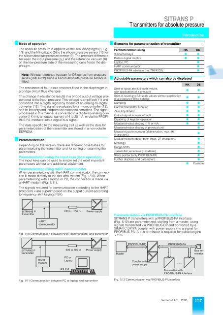
Parameterization using HART communicator<br />
When parameterizing with the HART communicator, the connection<br />
is made directly to the two-wire system (Fig. 1/10). When<br />
parameterizing with a laptop or PC, the connection is made via<br />
a HART modem (Fig. 1/11).<br />
The signals required for communication according to the HART<br />
protocol 5.x are superimposed on the output current according<br />
to frequency shift keying (FSK).<br />
Start-of-scale and full-scale values without application<br />
of a pressure ("Blind setting")<br />
4 4<br />
Damping 4 4<br />
Current transmitter function 4 4<br />
Zero adjustment 4 4<br />
Output signal in event of fault 4 4<br />
Disabling of keys for operation 4 4<br />
Measured-value display in % or mA 4 4<br />
Measured-value display of physical unit 4<br />
Measuring-point number (abbreviation, max. 16<br />
characters)<br />
4<br />
Measuring-point description (max. 27 characters) 4<br />
Message 4<br />
Range limits 4<br />
Transmitter version (e.g. material) 4<br />
Slave pointer (only PROFIBUS-PA) 4<br />
Further displays and parameters 4<br />
4 Possible<br />
+<br />
<strong>SITRANS</strong> P<br />
transmitter<br />
HART<br />
communicator<br />
230 to 1100 W<br />
Power supply<br />
Fig. 1/10 Communication between HART communicator and transmitter<br />
Parameterization via PROFIBUS-PA interface<br />
<strong>SITRANS</strong> P transmitters with a PROFIBUS-PA interface<br />
(Fig. 1/12) are parameterized, starting from a master, using<br />
signals transmitted via PROFIBUS-DP and converted by a<br />
SIMATIC DP/PA coupler with power supply into a signal for<br />
PROFIBUS-PA. A bus terminator is required for cable lengths<br />
> 2 m.<br />
PROFIBUS-DP<br />
PROFIBUS-PA<br />
T<br />
<strong>SITRANS</strong> P<br />
transmitter<br />
HART<br />
modem<br />
230 to 500 W<br />
PC or<br />
Laptop<br />
Power supply<br />
Master<br />
Coupler with<br />
power supply<br />
+<br />
.......<br />
Bus terminator<br />
RS 232<br />
Transmitter with<br />
PROFIBUS-PA interface<br />
Fig. 1/11 Communication between PC or laptop and transmitter<br />
Fig. 1/12 Communication via PROFIBUS-PA interface<br />
Siemens FI 01 · 2000 1/17