SITRANS P
SITRANS P
SITRANS P

You also want an ePaper? Increase the reach of your titles
YUMPU automatically turns print PDFs into web optimized ePapers that Google loves.
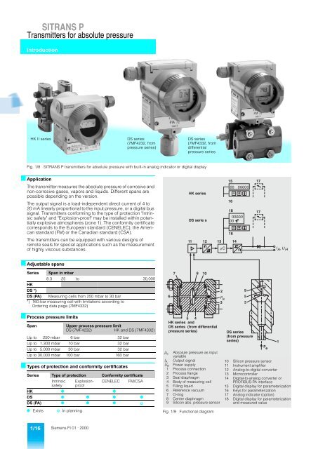
<strong>SITRANS</strong> P<br />
Transmitters for absolute pressure<br />
Introduction<br />
HK II series<br />
DS series<br />
(7MF4232, from<br />
pressure series)<br />
DS series<br />
(7MF4332, from<br />
differential<br />
pressure series<br />
Fig. 1/8<br />
<strong>SITRANS</strong> P transmitters for absolute pressure with built-in analog indicator or digital display<br />
■ Application<br />
The transmitter measures the absolute pressure of corrosive and<br />
non-corrosive gases, vapors and liquids. Different spans are<br />
possible depending on the version.<br />
The output signal is a load-independent direct current of 4 to<br />
20 mA linearly proportional to the input pressure, or a digital bus<br />
signal. Transmitters conforming to the type of protection "Intrinsic<br />
safety" and "Explosion-proof" may be installed within potentially<br />
explosive atmospheres (zone 1). The conformity certificate<br />
corresponds to the European standard (CENELEC), the American<br />
standard (FM) or the Canadian standard (CSA).<br />
The transmitters can be equipped with various designs of<br />
remote seals for special applications such as the measurement<br />
of highly viscous substances.<br />
HK series<br />
DS serie s<br />
11 12 13 14<br />
mC<br />
15 17<br />
00 00000<br />
16<br />
M<br />
18 17<br />
00000<br />
00<br />
16<br />
M<br />
I A , U H<br />
■ Adjustable spans<br />
Series Span in mbar<br />
8.3 25 to 30,000<br />
HK<br />
DS *)<br />
DS (PA) Measuring cells from 250 mbar to 30 bar<br />
*) 160-bar measuring cell with limitations according to<br />
Ordering data page (7MF4332)<br />
6<br />
7 8 10<br />
2<br />
p e<br />
3<br />
9<br />
5<br />
3<br />
■ Process pressure limits<br />
Span<br />
Upper process pressure limit<br />
DS (7MF4232)<br />
HK and DS (7MF4332)<br />
Up to 250 mbar 6 bar 32 bar<br />
Up to 1,300 mbar 10 bar 32 bar<br />
Up to 5,000 mbar 30 bar 32 bar<br />
Up to 30,000 mbar 100 bar 160 bar<br />
■ Types of protection and conformity certificates<br />
Series Type of protection Conformity certificate<br />
Intrinsic Explosionproof<br />
CENELEC FM/CSA<br />
safety<br />
HK 4 4<br />
DS 4 4 4 4<br />
DS (PA) 4 4 4 o<br />
4 Exists o In planning<br />
5 4<br />
HK series and<br />
DS series (from differential<br />
pressure series)<br />
p e Absolute pressure as input<br />
variable<br />
I A Output signal<br />
U H Power supply<br />
1 Process connection<br />
2 Process flange<br />
3 Seal diaphragm<br />
4 Body of measuring cell<br />
5 Filling liquid<br />
6 Reference vacuum<br />
7 O-ring<br />
8 Center diaphragm<br />
9 Silicon abs. pressure sensor<br />
Fig. 1/9<br />
Functional diagram<br />
DS series<br />
(from pressure<br />
series)<br />
p<br />
e<br />
10 Silicon pressure sensor<br />
11 Instrument amplifier<br />
12 Analog-to-digital converter<br />
13 Microcontroller<br />
14 Digital-to-analog converter or<br />
PROFIBUS-PA interface<br />
15 Digital display for parameterization<br />
16 Keys for parameterization<br />
17 Analog indicator (option)<br />
18 Digital display for parameterization<br />
and measured value<br />
1<br />
1/16<br />
Siemens FI 01 · 2000
<strong>SITRANS</strong> P<br />
Transmitters for absolute pressure<br />
Introduction<br />
■ Mode of operation<br />
■ Elements for parameterization of transmitter<br />
The absolute pressure is applied via the seal diaphragm (3, Fig. Parameterization using HK DS<br />
1/9) and the filling liquid (5) to the silicon pressure sensor (10) or<br />
3 external keys 4 4<br />
the silicon absolute pressure sensor (9). The pressure difference<br />
between the input pressure (p e ) and the reference vacuum (6) Built-in digital display 4 4<br />
on the low-pressure side of the measuring cells flexes the diaphragm.<br />
Laptop, PC<br />
HART communicator<br />
PROFIBUS-PA interface (not 7MF4232)<br />
4<br />
4<br />
4<br />
Note: Without reference vacuum for DS series from pressure<br />
series (7MF4232) since a silicon absolute pressure sensor is<br />
fitted.<br />
■ Adjustable parameters which can also be displayed<br />
HK DS<br />
The resistance of four piezo-resistors fitted in the diaphragm in Start-of-scale and full-scale values<br />
a bridge circuit thus changes.<br />
with application of a pressure<br />
4 4<br />
This change in resistance results in a bridge output voltage proportional<br />
to the input pressure. This voltage is amplified (11) and<br />
converted into a digital signal by means of an analog-to-digital<br />
converter (12). This signal is evaluated by a microcontroller (13),<br />
and its linearity and temperature response corrected. The signal<br />
processed in this manner is converted in a digital-to-analog converter<br />
(14) into an output current of 4 to 20 mA, or via the PROFI-<br />
BUS-PA interface into a digital bus signal.<br />
The data specific to the measuring cell as well as the data for<br />
parameterization of the transmitter are stored in a non-volatile<br />
EEPROM.<br />
■ Parameterization<br />
Depending on the version, there are different possibilities for<br />
parameterizing the transmitter and for setting or scanning the<br />
parameters.<br />
Parameterization using the input keys (local operation)<br />
The input keys can be used to simply set the most important<br />
parameters without any additional equipment.<br />
Parameterization using HART communicator<br />
When parameterizing with the HART communicator, the connection<br />
is made directly to the two-wire system (Fig. 1/10). When<br />
parameterizing with a laptop or PC, the connection is made via<br />
a HART modem (Fig. 1/11).<br />
The signals required for communication according to the HART<br />
protocol 5.x are superimposed on the output current according<br />
to frequency shift keying (FSK).<br />
Start-of-scale and full-scale values without application<br />
of a pressure ("Blind setting")<br />
4 4<br />
Damping 4 4<br />
Current transmitter function 4 4<br />
Zero adjustment 4 4<br />
Output signal in event of fault 4 4<br />
Disabling of keys for operation 4 4<br />
Measured-value display in % or mA 4 4<br />
Measured-value display of physical unit 4<br />
Measuring-point number (abbreviation, max. 16<br />
characters)<br />
4<br />
Measuring-point description (max. 27 characters) 4<br />
Message 4<br />
Range limits 4<br />
Transmitter version (e.g. material) 4<br />
Slave pointer (only PROFIBUS-PA) 4<br />
Further displays and parameters 4<br />
4 Possible<br />
+<br />
<strong>SITRANS</strong> P<br />
transmitter<br />
HART<br />
communicator<br />
230 to 1100 W<br />
Power supply<br />
Fig. 1/10 Communication between HART communicator and transmitter<br />
Parameterization via PROFIBUS-PA interface<br />
<strong>SITRANS</strong> P transmitters with a PROFIBUS-PA interface<br />
(Fig. 1/12) are parameterized, starting from a master, using<br />
signals transmitted via PROFIBUS-DP and converted by a<br />
SIMATIC DP/PA coupler with power supply into a signal for<br />
PROFIBUS-PA. A bus terminator is required for cable lengths<br />
> 2 m.<br />
PROFIBUS-DP<br />
PROFIBUS-PA<br />
T<br />
<strong>SITRANS</strong> P<br />
transmitter<br />
HART<br />
modem<br />
230 to 500 W<br />
PC or<br />
Laptop<br />
Power supply<br />
Master<br />
Coupler with<br />
power supply<br />
+<br />
.......<br />
Bus terminator<br />
RS 232<br />
Transmitter with<br />
PROFIBUS-PA interface<br />
Fig. 1/11 Communication between PC or laptop and transmitter<br />
Fig. 1/12 Communication via PROFIBUS-PA interface<br />
Siemens FI 01 · 2000 1/17
<strong>SITRANS</strong> P<br />
Transmitters for absolute pressure<br />
Technical data<br />
■ Technical data<br />
HK<br />
7MF4320<br />
DS<br />
7MF4232<br />
(from pressure<br />
transmitter series)<br />
Application See page 1/16<br />
Mode of operation<br />
Measuring principle<br />
Input<br />
Measured variable<br />
See page 1/17<br />
Piezo-resistive<br />
Absolute pressure<br />
DS<br />
7MF4332<br />
(from differential pressure<br />
transmitter series)<br />
DS (PROFIBUS-PA)<br />
7MF4332<br />
Measuring range<br />
• Span (continuously adjustable) 25 mbar to 30 bar 8.3 mbar to 30 bar 8.3 mbar to 30 bar Measuring cells from<br />
250 mbar to 30 bar<br />
• Lower measuring limit<br />
- Measuring cell with silicone oil filling 0 mbar<br />
- Measuring cell with inert filling liquid<br />
For process temp. -20 °C < J ˆ 60 °C – 30 mbar – –<br />
For process temp. +60 °C < J ˆ 100 °C – 30 mbar + 20 mbar · – –<br />
(J - 60)<br />
• Upper measuring limit 100 % of max. span 100 % of max. span 100 % of max. span –<br />
• Start-of-scale (continuously adjustable)<br />
Between the measuring<br />
limits<br />
Between the measuring<br />
limits<br />
Between the measuring<br />
limits<br />
Output<br />
Output signal 4 to 20 mA 4 to 20 mA 4 to 20 mA Digital bus signal<br />
• Lower limit 3.84 mA 3.84 mA 3.84 mA Digital status signal<br />
• Upper limit 22 mA 20.5 or 22 mA 20.5 or 22 mA Digital status signal<br />
• Electric damping<br />
- Adjustable time constant 0 to 100 s<br />
• Current transmitter Adjustable to 3.6, 4.0,<br />
12.0, 20.0 or 22.8 mA<br />
Adjustable from<br />
3.6 to 22.8 mA<br />
Adjustable from<br />
3.6 to 22.8 mA<br />
Signal on alarm 3.6 or 22.8 mA 3.6 or 22.8 mA 3.6 or 22.8 mA Digital status signal<br />
Load<br />
• Without HART communication<br />
R B ˆ (U H - 11 V)/<br />
0.023 A in W,<br />
U H : power supply in V<br />
R B ˆ (U H - 11 V)/<br />
0.023 A in W,<br />
U H : power supply in V<br />
R B ˆ (U H - 11 V)/<br />
0.023 A in W,<br />
U H : power supply in V<br />
–<br />
• With HART communication – R B = 230 to 500/1100 W R B = 230 to 500/1100 W –<br />
Characteristic<br />
Linear<br />
Accuracy<br />
Reference conditions<br />
Error in measurement (including hysteresis<br />
and repeatability)<br />
• Repeatability<br />
• Hysteresis<br />
Response time (T 63 , without electric damping)<br />
Long-term drift<br />
Increasing characteristic, start-of-scale 0 bar, stainless steel seal diaphragm, silicone oil filling and<br />
limit point setting.<br />
r = max. span/set span<br />
ˆ 0.1 % ˆ 0.1 % at r ˆ 10<br />
ˆ 0.2 % at 10 < r ˆ 30<br />
ˆ 0.2 % / 12 months with<br />
max. span<br />
ˆ 0.1 % at r ˆ 10<br />
0.2 at 10 < r ˆ 30<br />
Included in error in measurement<br />
Included in error in measurement<br />
Approx. 0.2 s<br />
ˆ 0.2 % / 12 months with<br />
max. span<br />
ˆ 0.2 % / 12 months with<br />
max. span<br />
–<br />
–<br />
ˆ 0.1 %<br />
ˆ 0.2 % / 12 months<br />
Ambient temperature effect<br />
• At -10 to +60 °C ˆ (0.1 · r + 0.2) % ˆ (0.1 · r + 0.2) % ˆ (0.1 · r + 0.2) % ˆ 0.3 %<br />
• At -40 to -10 °C and +60 to +85 °C ˆ (0.1 · r + 0.15) % /<br />
10 K<br />
ˆ (0.1 · r + 0.15) % /<br />
10 K<br />
ˆ (0.1 · r + 0.15) % /<br />
10 K<br />
ˆ 0.25 %/ 10 K<br />
Influence of mounting position ˆ 0.7 mbar per 10°<br />
inclination<br />
Influence of power supply<br />
ˆ 0.05 mbar per 10°<br />
inclination<br />
ˆ 0.7 mbar per 10°<br />
inclination<br />
ˆ 0.005 % per 1 V change in voltage<br />
Rated operating conditions<br />
Installation conditions<br />
• Installation instructions Any mounting position Process connection<br />
pointing vertically downwards<br />
Ambient conditions<br />
• Ambient temperature (observe temperature<br />
class in potentially explosive atmospheres)<br />
- Measuring cell with silicone oil filling -40 to 85 °C<br />
Any mounting position<br />
ˆ 0.7 mbar per 10°<br />
inclination<br />
Any mounting position<br />
- Measuring cell with inert filling liquid – -20 to +85 °C - –<br />
- - Digital display – -20 to +85 °C -20 to +85 °C -20 to +85 °C<br />
1/18<br />
Siemens FI 01 · 2000
<strong>SITRANS</strong> P<br />
Transmitters for absolute pressure<br />
Technical data<br />
■ Technical data<br />
Ambient conditions (continued)<br />
HK<br />
7MF4320<br />
DS<br />
7MF4232<br />
(from pressure<br />
transmitter series)<br />
DS<br />
7MF4332<br />
(from differential pressure<br />
transmitter series)<br />
• Ambient temperature limits<br />
See ambient temperature<br />
• Storage temperature -50 to +85 °C<br />
• Climate class<br />
- Condensation Permissible<br />
• Degree of protection (to EN 60 529) IP 65<br />
• Electromagnetic compatibility<br />
- Emitted interference To EN 50 081-1<br />
- Noise immunity To EN 50 082-2 and NAMUR NE 21<br />
Medium conditions<br />
• Process temperature<br />
- Measuring cell with silicone oil filling -40 to +100 °C<br />
(-40 to +85 °C for 30-bar<br />
cell)<br />
-40 to +100 °C -40 to +100 °C<br />
(-40 to +85 °C for 30-bar<br />
cell)<br />
DS (PROFIBUS-PA)<br />
7MF4332<br />
-40 to +100 °C<br />
(-40 to +85 °C for 30-bar<br />
cell)<br />
- Measuring cell with inert filling liquid – -20 to +100 °C – –<br />
• Process temperature limits<br />
See process temperature<br />
• Process pressure limits See page 1/16<br />
Design<br />
Weight (without options) Approx. 4.5 kg Approx. 1.5 kg Approx. 4.5 kg Approx. 4.7 kg<br />
Dimensions See Fig. 1/13 See Fig. 1/14 See Fig. 1/15 See Fig. 1/15<br />
Material<br />
• Wetted parts materials<br />
- Connection shank – Stainless steel, mat. No. – –<br />
1.4401 or Hastelloy C4,<br />
mat. No. 2.4610<br />
- Oval flange – Stainless steel, mat. No.<br />
1.4401<br />
– –<br />
- Seal diaphragm Stainless steel, mat. No.<br />
1.4404, Hastelloy C276,<br />
mat. No. 2.4819,<br />
tantalum, Monel, mat.<br />
No. 2.4360 or gold<br />
- Process flanges and sealing screw Stainless steel, mat. No.<br />
1.4408, Hastelloy C4,<br />
mat. No. 2.4610, or<br />
Monel, mat. No. 2.4360<br />
Stainless steel, mat. No.<br />
1.4404, Hastelloy C276,<br />
mat. No. 2.4819<br />
Stainless steel, mat. No.<br />
1.4404, Hastelloy C276,<br />
mat. No. 2.4819,<br />
tantalum, Monel, mat.<br />
No. 2.4360 or gold<br />
– Stainless steel, mat. No.<br />
1.4408, Hastelloy C4,<br />
mat. No. 2.4610, or<br />
Monel, mat. No. 2.4360<br />
- Measuring cell parts Stainless steel, mat. No. 1.4401<br />
- O-ring FPM, PTFE, FEP,<br />
FFPM or NBR<br />
• Non-wetted parts materials<br />
- Electronics housing Die-cast aluminium, low<br />
in copper, GD-ALSi 12,<br />
polyester-based lacquer,<br />
stainless steel rating<br />
plate<br />
- Process flange screws Steel, galvanized and<br />
yellow-passivized, or<br />
stainless steel<br />
– FPM, PTFE, FEP,<br />
FFPM or NBR<br />
Die-cast aluminium, low<br />
in copper, GD-ALSi 12,<br />
or stainless steel precision<br />
casting, polyesterbased<br />
lacquer, stainless<br />
steel rating plate<br />
Die-cast aluminium, low<br />
in copper, GD-ALSi 12,<br />
or stainless steel precision<br />
casting, polyesterbased<br />
lacquer, stainless<br />
steel rating plate<br />
– Steel, galvanized and<br />
yellow-passivized, or<br />
stainless steel<br />
Stainless steel, mat. No.<br />
1.4404, Hastelloy C276,<br />
mat. No. 2.4819,<br />
tantalum, Monel, mat.<br />
No. 2.4360 or gold<br />
Stainless steel, mat. No.<br />
1.4408, Hastelloy C4,<br />
mat. No. 2.4610, or<br />
Monel, mat. No. 2.4360<br />
FPM, PTFE, FEP,<br />
FFPM or NBR<br />
Die-cast aluminium, low<br />
in copper, GD-ALSi 12,<br />
or stainless steel precision<br />
casting, polyesterbased<br />
lacquer, stainless<br />
steel rating plate<br />
Steel, galvanized and<br />
yellow-passivized, or<br />
stainless steel<br />
- Mounting bracket (option) Steel, galvanized and yellow-passivized, or stainless steel<br />
Measuring cell filling Silicone oil Silicone oil or inert filling<br />
liquid<br />
Silicone oil<br />
Silicone oil<br />
Process connection Female thread ¼ - 18<br />
NPT and flange connection<br />
to DIN 19 213 with<br />
mounting thread M10 or<br />
7 / 16 - 20 UNF<br />
Female thread ½ - 14<br />
NPT or connection<br />
shank G½A to DIN<br />
16 288 or oval flange<br />
Female thread ¼ - 18<br />
NPT and flange connection<br />
to DIN 19 213 with<br />
mounting thread M10 or<br />
7 / 16 - 20 UNF<br />
Female thread ¼ - 18<br />
NPT and flange connection<br />
to DIN 19 213 with<br />
mounting thread M10 or<br />
7 / 16 - 20 UNF<br />
Electrical connection<br />
Screw terminals, cable<br />
inlet via screwed gland<br />
Pg 13.5 (adapter), M20<br />
x 1.5 or ½ - 14 NPT, or<br />
Han 7D/Han 8U plug<br />
Screw terminals, cable<br />
inlet via screwed gland<br />
Pg 13.5 (adapter), M20<br />
x 1.5 or ½ - 14 NPT, or<br />
Han 7D/Han 8U plug<br />
Screw terminals, cable<br />
inlet via screwed gland<br />
Pg 13.5 (adapter), M20<br />
x 1.5 or ½ - 14 NPT, or<br />
Han 7D/Han 8U plug<br />
Screw terminals, cable<br />
inlet via screwed gland<br />
M20 x 1.5 or<br />
½ - 14 NPT<br />
Siemens FI 01 · 2000 1/19
<strong>SITRANS</strong> P<br />
Transmitters for absolute pressure<br />
Technical data<br />
■ Technical data<br />
HK<br />
7MF4320<br />
Displays and controls<br />
Input keys<br />
Analog indicator (option) Linear scale 0 to 100 %<br />
or customer-specific<br />
scale<br />
DS<br />
7MF4232<br />
(from pressure<br />
transmitter series)<br />
DS<br />
7MF4332<br />
(from differential pressure<br />
transmitter series)<br />
3 for local programming directly on transmitter<br />
Linear scale 0 to 100 %<br />
or customer-specific<br />
scale<br />
Linear scale 0 to 100 %<br />
or customer-specific<br />
scale<br />
DS (PROFIBUS-PA)<br />
7MF4332<br />
Digital display – Yes Yes Yes<br />
Power supply<br />
Terminal voltage on transmitter<br />
DC 11 to 45 V<br />
DC 11 to 45 V<br />
DC 11 to 45 V<br />
Provided via bus<br />
DC 11 to 30 V in DC 11 to 30 V in DC 11 to 30 V in DC 9 to 32 V<br />
intrinsically-safe mode intrinsically-safe mode intrinsically-safe mode DC 9 to 23 V in<br />
intrinsically-safe mode<br />
Ripple – U pp ˆ 0.2 V (47 to<br />
125 Hz)<br />
Noise – U rms ˆ 1.2 mV (0.5 to<br />
10 kHz)<br />
U pp ˆ 0.2 V (47 to<br />
125 Hz)<br />
U rms ˆ 1.2 mV (0.5 to<br />
10 kHz)<br />
Certificates and approvals<br />
CENELEC To DIN EN 50 014, DIN 50 018 and DIN EN 50 020<br />
• Intrinsic safety<br />
EEx ia IIC T4 or T5 or T6 EEx ia IIC T4 or T5 or T6 EEx ia IIC T4 or T5 or T6 EEx ib IIC T4<br />
- Conformity certificate PTB No. Ex-92.C.2146 PTB No. Ex-94.C.2090 PTB No. Ex-94.C.2090 PTB No. Ex-97.D.2178<br />
- Max. ambient temperature +85 °C temp. class T4<br />
+75 °C temp. class T5<br />
+60 °C temp. class T6<br />
- Connection to certified intrinsically-safe<br />
circuits with maximum values<br />
U o = 30 V<br />
I k = 100 mA<br />
P = 750 mW<br />
+85 °C temp. class T4<br />
+75 °C temp. class T5<br />
+60 °C temp. class T6<br />
U o = 30 V<br />
I k = 100 mA<br />
P = 750 mW<br />
+85 °C temp. class T4<br />
+75 °C temp. class T5<br />
+60 °C temp. class T6<br />
U o = 30 V<br />
I k = 100 mA<br />
P = 750 mW<br />
–<br />
–<br />
–<br />
+80 °C temp. class T4<br />
U o = 17.5 V<br />
I k = 128 mA<br />
P = 1.8 W<br />
- Effective internal inductance L i ˆ 0.6 mH L i ˆ 0.6 mH L i ˆ 0.6 mH L i ˆ 7.2 µH<br />
- Effective internal capacitance C i ˆ 6 nF C i ˆ 8 nF C i ˆ 8 nF C i ˆ 0.6 nF<br />
• Explosion-proof – EEx d IIC T5 and T6 EEx d IIC T5 and T6 EEx d IIC T5 and T6<br />
- Conformity certificate – PTB No. Ex-94.C.1021 PTB No. Ex-94.C.1021 PTB No. Ex-94.C.1021<br />
- Max. ambient temperature – +85 °C temp. class T5<br />
+75 °C temp. class T6<br />
TÜV<br />
To DIN VDE<br />
0165/02.91,<br />
Section 6.3<br />
+85 °C temp. class T5<br />
+75 °C temp. class T6<br />
– To DIN VDE<br />
0165/02.91,<br />
Section 6.3<br />
+85 °C temp. class T5<br />
+75 °C temp. class T6<br />
To DIN VDE<br />
0165/02.91,<br />
Section 6.3<br />
• Ex-approved zone 2n Ex n V II T4 In planning Ex n V II T4 Ex n V II T4<br />
- Registration number 08/220/1092/6 – 08/220/1092/6 TÜV 97 ATEX 1247<br />
FMRC (Factory Mutual Research Corp.)<br />
• Intrinsic safety and explosion-proof – – 2Y9A7.AX (3610, 3615) –<br />
• Explosion-proof – – For class I, division 1,<br />
groups A, B, C and D<br />
• Dust-ignition proof – – For class II, division 1,<br />
groups E, F and G,<br />
indoor and outdoor<br />
(NEMA 4X) hazardous<br />
(classified) locations<br />
• Intrinsically safe – – With entity, for use in<br />
class I, division 1,<br />
groups A, B, C, D, E, F<br />
and G, indoor and outdoor<br />
(NEMA 4X) hazardous<br />
(classified)<br />
locations<br />
–<br />
• Entity parameters – – V max = 30 V<br />
I max = 100 mA<br />
L i = 0.6 mH<br />
C i = 8 nF<br />
CSA (Certificate of Compliance) – – No. LR 104225-1<br />
Class 2258 02 and<br />
Class 2258 03<br />
For class I, division 1,<br />
groups A, B, C and D<br />
For class II, division 1,<br />
groups E, F and G,<br />
indoor and outdoor<br />
(NEMA 4X) hazardous<br />
(classified) locations<br />
–<br />
–<br />
1/20<br />
Siemens FI 01 · 2000
<strong>SITRANS</strong> P<br />
Transmitters for absolute pressure<br />
Technical data<br />
■ Technical data<br />
DS<br />
7MF4232, 7MF4332<br />
DS with PROFIBUS-PA<br />
7MF4332<br />
Communication<br />
Load when connecting a<br />
• HART communicator 230 to 1100 W -<br />
• HART modem 230 to 500 W -<br />
Cable<br />
2-wire screened: ˆ 3.0 km<br />
–<br />
Multi-core screened: ˆ 1.5 km<br />
Protocol HART, version 5.x Layers 1 and 2 according to PROFIBUS-PA<br />
Intrinsically-safe to IEC 1158-2<br />
Slave function<br />
Layer 7 (protocol layer) according to PROFI-<br />
BUS-DP functions (all data acyclic, measured<br />
value and status cyclic in addition)<br />
PC/laptop requirements<br />
IBM-compatible,<br />
main memory > 32 Mbyte,<br />
hard disk > 70 Mbyte,<br />
RS 232 interface,<br />
VGA graphics<br />
–<br />
Software for PC/laptop WINDOWS 95/NT 4.0 and SIMATIC PDM –<br />
Device and remote control functions – More than 100 parameters according to PROFI-<br />
BUS-PA profile<br />
Device profile taking into account previous<br />
HART functions for<br />
– Measuring-point designation<br />
Device organization<br />
Device type<br />
Device materials<br />
Hardware and firmware versions<br />
Sensor data<br />
Adjustment points<br />
Type and materials of process connection<br />
Sensor temperature<br />
Limit monitoring<br />
Slave pointer functions<br />
Alarm signalling<br />
Status information<br />
Filter time<br />
Measured value in selectable dimension<br />
Device address – 1 when delivered<br />
Current consumption of device – Approx. 18 mA<br />
Electronic current limiting – I max ˆ 27 mA in event of fault, output twice<br />
Measured-value resolution – 3 x 10 -5 referred to full-scale value<br />
Siemens FI 01 · 2000 1/21
<strong>SITRANS</strong> P<br />
Transmitters for absolute pressure<br />
Ordering data<br />
7MF4320, HK series<br />
<strong>SITRANS</strong> P<br />
■ Ordering data<br />
.<br />
<strong>SITRANS</strong> P transmitter<br />
for absolute pressure, HK series<br />
Two-wire system, Instruction Manual (in<br />
same language as rating plate; see<br />
"Further designs"), 1 sealing screw<br />
(same material as process flange),<br />
measuring cell filling: silicone oil,<br />
measuring cell cleaning: normal<br />
Span<br />
25 to 250 mbar<br />
130 to 1,300 mbar<br />
500 to 5,000 mbar<br />
3,000 to 30,000 mbar<br />
Wetted parts materials<br />
(Process flanges made of stainless steel)<br />
Seal diaphragm Parts of meas. cell<br />
Stainless steel Stainless steel<br />
Hastelloy Stainless steel<br />
Hastelloy Hastelloy<br />
Tantalum Tantalum<br />
Monel Monel<br />
Gold<br />
Gold<br />
Version for<br />
remote seal 1 )<br />
Process connection<br />
Female thread ¼ - 18 NPT and<br />
flange connection to DIN 19 213<br />
• With mounting thread M10<br />
• With mounting thread 7 / 16 - 20 UNF<br />
Non-wetted parts materials<br />
Process flange Electronics housing<br />
screws<br />
Steel<br />
Die-cast aluminium<br />
Stainless steel Die-cast aluminium<br />
Explosion protection<br />
• Without explosion protection<br />
• With explosion protection (CENELEC)<br />
Type of protection:<br />
"Intrinsic safety" (EEx ia)<br />
• Use in zone 2n (TÜV)<br />
Electrical connection/cable inlet<br />
• Screwed gland Pg 13.5 (adapter)<br />
• Screwed gland M20 x 1.5<br />
• Screwed gland ½ -14 NPT<br />
• Han 7D plug<br />
Indicator<br />
• Without<br />
• Housing cover with analog indicator<br />
- Scale 0 to 100 %, linear divisions<br />
- Scale as specified<br />
(Order code Y20 required)<br />
Example for ordering<br />
Item line:7MF4320-1HA00-1AA5-Z<br />
B line:A01 + Y01 + Y20<br />
C line:Y01: 0 to 20 bar<br />
C line:Y20: 0 to 20 bar<br />
Order No.<br />
7MF4320-<br />
1 7777 -1777<br />
D<br />
F<br />
G<br />
H<br />
A<br />
B<br />
C<br />
E<br />
H<br />
L 2<br />
Y<br />
0<br />
2<br />
0<br />
2<br />
A<br />
B<br />
E<br />
A<br />
B<br />
C<br />
D<br />
1<br />
3<br />
5<br />
■ Ordering data<br />
Further designs<br />
Please add "Z" to Order No. and specify<br />
Order code(s).<br />
Transmitter with mounting bracket<br />
made of<br />
•Steel<br />
• Stainless steel<br />
Instead of FPM (Viton), process flange<br />
O-ring made of:<br />
• PTFE (Teflon)<br />
• FEP (with silicone core,<br />
approved for food)<br />
• FFPM (Kalrez)<br />
• NBR (Buna N)<br />
Han 7D plug (metal, gray)<br />
Han 8U plug (instead of Han 7D)<br />
Sealing screw ¼ - 18 NPT with valve (in<br />
material of process flange)<br />
Rating plate inscription<br />
(instead of German)<br />
•English<br />
• French<br />
• Spanish<br />
• Italian<br />
Manufacturer’s test certificate M to<br />
DIN 55 350, Part 18 and to ISO 9001<br />
Acceptance test certificate B to DIN 50<br />
049/EN 10 204-3.1B<br />
Factory certificate to<br />
DIN 50 049-2.2/EN 10 204-2.2<br />
Acid gas version to NACE (only<br />
together with seal diaphragm made of<br />
Hastelloy and process flange screws<br />
made of stainless steel)<br />
Use<br />
• In zone 10/11 (basic unit EEx ia)<br />
• In zone 0 (basic unit EEx ia)<br />
Process flange made of:<br />
• Hastelloy<br />
• Monel<br />
See page 1/54 for four-wire system<br />
Additional information<br />
Please add "Z" to Order No. and specify<br />
Order code(s) and plain text.<br />
Order code<br />
A01<br />
A02<br />
A20<br />
A21<br />
A22<br />
A23<br />
A30<br />
A31<br />
A40<br />
B11<br />
B12<br />
B13<br />
B14<br />
C11<br />
C12<br />
C14<br />
D07<br />
E01<br />
E02<br />
K01<br />
K02<br />
Measuring range to be set,<br />
specify in plain text:<br />
Y01: ... to ... mbar, bar, kPa, MPa Y01<br />
Measuring-point text (max. 16 characters),<br />
specify in plain text:<br />
Y15: ........................................... Y15<br />
Measuring-point number/identification<br />
(max. 27 characters), specify in plain<br />
text:<br />
Y16: ........................................... Y16<br />
Customer-specific scale for analog<br />
indicator, specify in plain text:<br />
Y20: ... to ... mbar, bar,<br />
kPa, MPa<br />
Y20<br />
Only the setting for "Y01" can be made in the factory.<br />
Power supply units: see page 2/50.<br />
1 ) Version 7MF4320-1DY.. only up to max. span 200 mbar.<br />
1/22 Siemens FI 01 · 2000
■ Ordering data<br />
.<br />
<strong>SITRANS</strong> P transmitter<br />
for absolute pressure, DS series<br />
Two-wire system, Smart version;<br />
Instruction Manual (in same language as<br />
rating plate;<br />
see "Further designs")<br />
Measuring cell Meas. cell<br />
filling<br />
cleaning<br />
Silicone oil Normal<br />
Inert liquid Grease-free<br />
Span<br />
8.3 to 250 mbar<br />
43 to 1,300 mbar<br />
160 to 5,000 mbar<br />
1,000 to 30,000 mbar<br />
Wetted parts materials<br />
Seal diaphragm Connection shank<br />
Stainless steel Stainless steel<br />
Hastelloy Stainless steel<br />
Hastelloy Hastelloy<br />
Version for remote seal 3 )<br />
Process connection<br />
• Connection shank G½A<br />
• Female thread ½ - 14 NPT<br />
• Oval flange and connection shank made<br />
of stainless steel<br />
- Mounting thread 7 / 16 - 20 UNF<br />
- Mounting thread M10<br />
Non-wetted parts materials<br />
• Housing made of die-cast aluminium<br />
• Housing: stainl. steel precision casting<br />
Explosion protection<br />
• Without explosion protection<br />
• With explosion protection (CENELEC)<br />
Type of protection:<br />
- "Intrinsic safety" (EEx ia)<br />
- "Explosion-proof" (EEx d) 1 )<br />
- "Intrinsic safety + explosion-proof"<br />
(EEx ia and EEx d) (in planning) 1 )<br />
• Use in zone 2n (TÜV) (in planning)<br />
• With explosion protection (FM + CSA)<br />
Intrinsic safety and explosion-proof<br />
(is + xp) (in planning) 1 )<br />
Electrical connection/cable inlet<br />
• Screwed gland Pg 13.5 (adapter) 2 )<br />
• Screwed gland M20 x 1.5<br />
• Screwed gland ½ -14 NPT<br />
• Han 7D plug 2 )<br />
Indicator<br />
• Basic version with housing cover<br />
without window (built-in digital display<br />
hidden)<br />
• Housing cover with analog indicator<br />
- Scale 0 to 100 %, linear divisions<br />
- Scale as specified<br />
(Order code Y20 required)<br />
• Housing cover with window<br />
(built-in digital display visible)<br />
Order No.<br />
7MF4232-<br />
77777 -1777<br />
1<br />
3<br />
D<br />
F<br />
G<br />
H<br />
A<br />
B<br />
C<br />
Y 0<br />
0<br />
1<br />
2<br />
3<br />
0<br />
3<br />
A<br />
B<br />
D<br />
P<br />
E<br />
NC<br />
A<br />
B<br />
C<br />
D<br />
1<br />
3<br />
5<br />
6<br />
■ Ordering data<br />
Further designs<br />
<strong>SITRANS</strong> P<br />
Transmitters for absolute pressure<br />
7MF4232, DS series<br />
(from pressure transmitter series)<br />
Please add "Z" to Order No. and<br />
specify Order code(s).<br />
Transm. with mount. bracket made of<br />
• Steel<br />
• Stainless steel<br />
Han 7D plug (metal, gray)<br />
Han 8U plug (instead of Han 7D)<br />
Rating plate inscription<br />
(instead of German)<br />
• English<br />
• French<br />
• Spanish<br />
• Italian<br />
Manufacturer’s test certificate M to<br />
DIN 55 350, Part 18 and to ISO 9001<br />
Acceptance test certificate B to<br />
DIN 50 049/EN 10 204-3.1B<br />
Factory certificate to<br />
DIN 50 049-2.2/EN 10 204-2.2<br />
Setting of upper limit of<br />
output signal to 22.0 mA<br />
Acid gas version to NACE (only<br />
together with seal diaphragm made of<br />
Hastelloy and process flange screws<br />
made of stainless steel)<br />
Order code<br />
Only the settings for "Y01" and "D05" can be made in the factory.<br />
See page 1/22 for example for ordering.<br />
Power supply units: see page 2/50.<br />
A01<br />
A02<br />
A30<br />
A31<br />
B11<br />
B12<br />
B13<br />
B14<br />
C11<br />
C12<br />
C14<br />
D05<br />
D07<br />
IP 68 (not together with Han 7D plug D12<br />
or screwed gland Pg 13.5)<br />
Use in zone 0 (basic device EEx ia) E02<br />
Oxygen application (max. 190 bar with E10<br />
oxygen measurement and inert filling<br />
liquid)<br />
See page 1/54 for four-wire system<br />
Additional information<br />
Please add "Z" to Order No. and<br />
specify Order code(s) and plain text.<br />
Measuring range to be set,<br />
specify in plain text:<br />
Y01: ... to ... mbar, bar, kPa, MPa Y01<br />
Measuring-point number/identification<br />
(max. 16 characters), specify in plain<br />
text:<br />
Y15<br />
Y15: ...........................................<br />
Measuring-point text (max. 27 characters),<br />
specify in plain text:<br />
Y16: ........................................... Y16<br />
Customer-specific scale for analog<br />
indicator, specify in plain text:<br />
Y20: ... to ... mbar, bar, kPa, MPa Y20<br />
1 ) Without cable gland.<br />
2 ) Not together with type of protection "Explosion-proof".<br />
3 ) Version 7MF4232-7DY.. only up to max. span 200 mbar.<br />
Siemens FI 01 · 2000 1/23
<strong>SITRANS</strong> P<br />
Transmitters for absolute pressure<br />
7MF4332, DS series<br />
(from differential pressure transmitter series)<br />
■ Ordering data<br />
.<br />
<strong>SITRANS</strong> P transmitter<br />
for absolute pressure, DS series<br />
Two-wire system, Smart version; Instruction<br />
Manual (in same language as rating plate;<br />
see "Further designs"), 1 sealing screw<br />
(same material as process flange),<br />
measuring cell filling: silicone oil,<br />
measuring cell cleaning: normal<br />
Span<br />
8.3 to 250 mbar<br />
43 to 1,300 mbar<br />
160 to 5,000 mbar<br />
1.0 to 30 bar<br />
5.3 to 160 bar<br />
Wetted parts materials<br />
Seal diaphragm Parts of meas. cell<br />
Stainless steel Stainless steel<br />
Hastelloy Stainless steel<br />
Hastelloy Hastelloy<br />
Tantalum Tantalum<br />
Monel Monel<br />
Gold 1 ) Gold<br />
Version for remote seal 3 )<br />
Process connection<br />
Female thread ¼ - 18 NPT and<br />
flange connection to DIN 19 213<br />
• With sealing screw opposite<br />
process connection<br />
- Mounting thread M10<br />
- Mounting thread 7 / 16 - 20 UNF<br />
• Sealing screw on side of<br />
process flanges<br />
- Mounting thread M10<br />
- Mounting thread 7 / 16 - 20 UNF<br />
Non-wetted parts materials<br />
Process flange screws Electronics housing<br />
Steel<br />
Die-cast aluminium<br />
Stainless steel Die-cast aluminium<br />
Stainless steel Stain. st. prec. cast.<br />
Explosion protection<br />
• Without explosion protection<br />
• With explosion protection (CENELEC)<br />
Type of protection:<br />
- "Intrinsic safety" (EEx ia)<br />
- "Explosion-proof" (EEx d) 5 )<br />
- "Intrinsic safety and explosion-proof"<br />
(EEx ia and EEx d) 5 )<br />
• Use in zone 2n (TÜV)<br />
• With explosion protection (FM + CSA)<br />
Intrinsic safety and explosion-proof (is + xp) 5 )<br />
Electrical connection/cable inlet<br />
• Screwed gland Pg 13.5 (adapter) 2 )<br />
• Screwed gland M20 x 1.5<br />
• Screwed gland ½ -14 NPT<br />
• Han 7D plug 2 )<br />
Indicator<br />
• Basic version with housing cover<br />
without window (built-in digital display<br />
hidden)<br />
• Housing cover with analog indicator<br />
- Scale 0 to 100 %, linear divisions<br />
- Scale as specified<br />
(Order code Y20 required)<br />
• Housing cover with window<br />
(built-in digital display visible)<br />
Order No.<br />
7MF4332-<br />
1 7777 -1777<br />
D<br />
F<br />
G<br />
H<br />
K E<br />
A<br />
B<br />
C<br />
E<br />
H<br />
L<br />
Y<br />
0<br />
2<br />
4 4 )<br />
6 4 )<br />
0<br />
2<br />
3<br />
A<br />
B<br />
D<br />
P 4 )<br />
E<br />
N C 4 )<br />
A<br />
B<br />
C<br />
D<br />
1<br />
3<br />
5<br />
6<br />
■ Ordering data<br />
Further designs<br />
Please add "Z" to Order No. and specify Order<br />
code(s).<br />
Transm. with mounting bracket made of<br />
• Steel<br />
• Stainless steel<br />
Instead of FPM (Viton), process flange O-ring made of<br />
• PTFE (Teflon)<br />
• FEP (with silicone core, approved for food)<br />
• FFPM (Kalrez)<br />
• NBR (Buna N)<br />
Han 7D plug (metal, gray)<br />
Han 8U plug (instead of Han 7D)<br />
Sealing screw ¼ - 18 NPT with valve<br />
(in material of process flange)<br />
Rating plate inscription (instead of German)<br />
• English<br />
• French<br />
• Spanish<br />
• Italian<br />
Manufacturer’s test certificate M to DIN 55 350,<br />
Part 18 and to ISO 9001<br />
Acceptance test certificate B to DIN 50 049/<br />
EN 10 204-3.1B<br />
Factory certificate to DIN 50 049-2.2/EN 10 204-2.2<br />
Setting of upper limit of<br />
output signal to 22 mA<br />
Acid gas version to NACE (only together with seal<br />
diaphragm made of Hastelloy and process flange<br />
screws made of stainless steel)<br />
Order code<br />
Only the settings for "Y01" and "D05" can be made in the factory.<br />
See page 1/22 for example for ordering<br />
Power supply units: see page 2/50.<br />
A01<br />
A02<br />
A20<br />
A21<br />
A22<br />
A23<br />
A30<br />
A31<br />
A40<br />
B11<br />
B12<br />
B13<br />
B14<br />
C11<br />
C12<br />
C14<br />
D05<br />
D07<br />
IP 68 (not together with Han 7D, Han 8U or<br />
D12<br />
Pg 13.5 plug)<br />
Use in zone 0 (basic device EEx ia) E02 4 )<br />
Vent on side for gas measurements H02 4 )<br />
Process flanges made of:<br />
• Hastelloy<br />
• Monel<br />
See page 1/54 for four-wire system<br />
Additional information<br />
Please add "Z" to Order No. and specify Order<br />
code(s) and plain text.<br />
Measuring range to be set, specify in plain text:<br />
K01 4 )<br />
K01 4 )<br />
Y01: ... to ... mbar, bar, kPa, MPa Y01<br />
Measuring-point number/identification<br />
(max. 16 characters), specify in plain text:<br />
Y15: ........................................... Y15<br />
Measuring-point text<br />
(max. 27 characters), specify in plain text:<br />
Y16: ........................................... Y16<br />
Customer-specific scale for analog indicator,<br />
specify in plain text:<br />
Y20: ... to ... mbar, bar, kPa, MPa Y20<br />
1 ) Only together with process flange screws made of stainless steel.<br />
2 ) Not together with type of protection "Explosion-proof".<br />
3 ) Version 7MF4332-1DY .. only up to max. span 200 mbar.<br />
4 ) Not for measuring cell 5.3 to 160 bar.<br />
5 ) Without cable gland.<br />
1/24<br />
Siemens FI 01 · 2000
■ Ordering data<br />
.<br />
<strong>SITRANS</strong> P transmitter for absolute<br />
pressure, DS series with<br />
PROFIBUS-PA<br />
Two-wire system, Smart version; Instruction<br />
Manual (in same language as rating<br />
plate; see "Further designs"), 1 sealing<br />
screw (same mat.l as process flange),<br />
measuring cell filling: silicone oil,<br />
measuring cell cleaning: normal<br />
Span<br />
Up to 250 mbar<br />
Up to 1,300 mbar<br />
Up to 5,000 mbar<br />
Up to 30,000 mbar<br />
Wetted parts materials<br />
(Process flanges made of stainless steel)<br />
Seal diaphragm Parts of meas. cell<br />
Stainless steel Stainless steel<br />
Hastelloy Stainless steel<br />
Hastelloy Hastelloy<br />
Tantalum Tantalum<br />
Monel<br />
Monel<br />
Gold 1 )<br />
Gold<br />
Version for remote seal 2 )<br />
Process connection<br />
Female thread ¼ - 18 NPT and<br />
flange connection to DIN 19 213<br />
• With sealing screw opposite<br />
process connection<br />
- Mounting thread M10<br />
- Mounting thread 7 / 16 - 20 UNF<br />
• Sealing screw on side of process flanges<br />
- Mounting thread M10<br />
- Mounting thread 7 / 16 - 20 UNF<br />
Non-wetted parts<br />
materials<br />
Process flange Stainl. steel prec. casting<br />
screws<br />
Steel<br />
Die-cast aluminium<br />
Stainless steel Die-cast aluminium<br />
Stainless steel Stainl. steel prec. casting<br />
Explosion protection<br />
•• Without explosion protection<br />
• With explosion protection<br />
Type of protection:<br />
"Explosion-proof" (EEx d)<br />
• Use in zone 2n (TÜV)<br />
• With explosion protection (FM)<br />
explosion-proof (xp)<br />
• With explosion protection EEx ib<br />
Electrical connection/cable inlet<br />
•• Screwed gland M20 x 1.5<br />
• Screwed gland ½ - 14 NPT<br />
Indicator<br />
•• Basic version with housing cover<br />
without window (built-in digital display<br />
hidden)<br />
• Housing cover with window<br />
(built-in digital display visible)<br />
Order No.<br />
7MF4332-<br />
1 7777 -1777-Z P01<br />
D<br />
F<br />
G<br />
H<br />
A<br />
B<br />
C<br />
E<br />
H<br />
L<br />
Y<br />
0<br />
2<br />
4<br />
6<br />
0<br />
2<br />
3<br />
A<br />
D<br />
E<br />
GC<br />
Q<br />
B<br />
C<br />
1<br />
6<br />
■ Ordering data<br />
Further designs<br />
<strong>SITRANS</strong> P<br />
Transmitters for absolute pressure<br />
7MF4332, DS series with PROFIBUS-PA<br />
Please add "Z" to Order No. and specify Order<br />
code(s).<br />
Transmitter with mounting bracket made of<br />
• Steel<br />
• Stainless steel<br />
Instead of FPM (Viton), process flange O-ring made<br />
of<br />
• PTFE (Teflon)<br />
• FEP (with silicone core, approved for food)<br />
• FFPM (Kalrez)<br />
• NBR (Buna N)<br />
Sealing screw ¼ - 18 NPT with valve<br />
(in material of process flange)<br />
Rating plate inscription (instead of German)<br />
• English<br />
Manufacturer’s test certificate M to DIN 55 350,<br />
Part 18 and to ISO 9001<br />
Acceptance test certificate B to DIN 50 049/<br />
EN 10 204-3.1B<br />
Factory certificate to DIN 50 049-2.2/EN 10 204-2.2<br />
Acid gas version to NACE (only together with seal<br />
diaphragm made of Hastelloy and process flange<br />
screws made of stainless steel)<br />
IP 68<br />
See page 1/22 for example for ordering<br />
Order code<br />
A01<br />
A02<br />
A20<br />
A21<br />
A22<br />
A23<br />
A40<br />
B11<br />
C11<br />
C12<br />
C14<br />
D07<br />
D12<br />
Vent on side for gas measurements<br />
H02<br />
Process flanges made of:<br />
• Hastelloy<br />
K01<br />
• Monel<br />
K02<br />
Additional information<br />
Please add "Z" to Order No. and specify Order<br />
code(s) and plain text.<br />
Measuring-point number/identification<br />
(max. 16 characters), specify in plain text:<br />
Y15: ........................................... Y15<br />
Measuring-point text<br />
(max. 27 characters), specify in plain text:<br />
Y16: ........................................... Y16<br />
1 ) Only together with process flange screws made of stainless steel.<br />
2 ) Version 7MF4332-1DY .. only up to max. span 200 mbar.<br />
Siemens FI 01 · 2000 1/25
<strong>SITRANS</strong> P<br />
Transmitters for absolute pressure<br />
Dimensional drawings<br />
240<br />
225<br />
176<br />
90<br />
62<br />
3 4 4<br />
100<br />
30 *<br />
227<br />
111<br />
92<br />
104<br />
107<br />
80<br />
5 6 8 7<br />
72<br />
68<br />
126<br />
105<br />
1 Process connection ¼ - 18 NPT<br />
2 Mounting thread M10 or 7 / 16 - 20 UNF<br />
3 Blanking plug (electrical connection possible)<br />
4 Screwed gland Pg 13.5 (adapter),<br />
M20 x 1.5 or<br />
½ - 14 NPT or<br />
Han 7D/Han 8U plug<br />
5 Indicator (option)<br />
6 Protective cover over keys<br />
7 Sealing screw<br />
8 Mounting bracket (option)<br />
with clamp for securing to a vertical or<br />
horizontal pipe (diam. 50 to 60 mm)<br />
41,3<br />
* 45 for Pg 13,5 with adapter<br />
54<br />
2<br />
1<br />
Fig. 1/13 Dimensions of HK series<br />
15<br />
138<br />
50<br />
28<br />
55 100<br />
30 *<br />
6<br />
2<br />
50<br />
20<br />
80<br />
5 4<br />
68 117<br />
3<br />
3<br />
171<br />
237<br />
1<br />
72<br />
120<br />
36,5<br />
123<br />
* for Pg 13,5 with adapter<br />
1 Process connection ½ - 14 NPT,<br />
connection shank G ½ A or oval flange<br />
2 Blanking plug<br />
3 Electrical connection:<br />
Screwed gland Pg 13.5 (adapter),<br />
M20 x 1.5 or ½ - 14 NPT or<br />
Han 7D/Han 8U plug<br />
Fig. 1/14 Dimensions of DS series (7MF4232)<br />
7<br />
4 Terminal side, analog indicator as option<br />
5 Electronics side, digital display<br />
6 Protective cover over keys<br />
7 Mounting bracket (option)<br />
105<br />
1/26<br />
Siemens FI 01 · 2000
<strong>SITRANS</strong> P<br />
Transmitters for absolute pressure<br />
Dimensional drawings<br />
15<br />
138 *<br />
50<br />
15<br />
30 **<br />
100<br />
7<br />
3<br />
50<br />
80<br />
20<br />
4<br />
198<br />
6<br />
5<br />
10<br />
9<br />
261<br />
1<br />
8<br />
2<br />
134<br />
11<br />
4<br />
72<br />
* 161 for DS series with PROFIBUS-PA<br />
105 ** 45 for Pg 13,5 with adapter<br />
68<br />
120<br />
1 Process connection ¼ - 18 NPT<br />
2 Mounting thread M10 or 7 / 16 - 20 UNF<br />
3 Blanking plug<br />
4 Electrical connection:<br />
screwed gland Pg 13.5 (adapter),<br />
(not DS series with PROFIBUS-PA)<br />
M20 x 1.5 or ½ - 14 NPT or<br />
Han 7D/Han 8U plug<br />
(not DS series with PROFIBUS-PA)<br />
5 Terminal side, analog indicator as option<br />
6 Electronics side, digital display as option<br />
7 Protective cover over keys<br />
8 Sealing screw<br />
9 Vent on side for liquid measurements<br />
10 Vent on side for gas measurements (suffix H02)<br />
11 Mounting bracket (option)<br />
Fig. 1/15 Dimensions of DS series (7MF4332) and DS series with PROFIBUS-PA<br />
Siemens FI 01 · 2000 1/27