Kit 3. LED DICE WITH SLOWDOWN - Ozitronics
Kit 3. LED DICE WITH SLOWDOWN - Ozitronics
Kit 3. LED DICE WITH SLOWDOWN - Ozitronics

You also want an ePaper? Increase the reach of your titles
YUMPU automatically turns print PDFs into web optimized ePapers that Google loves.
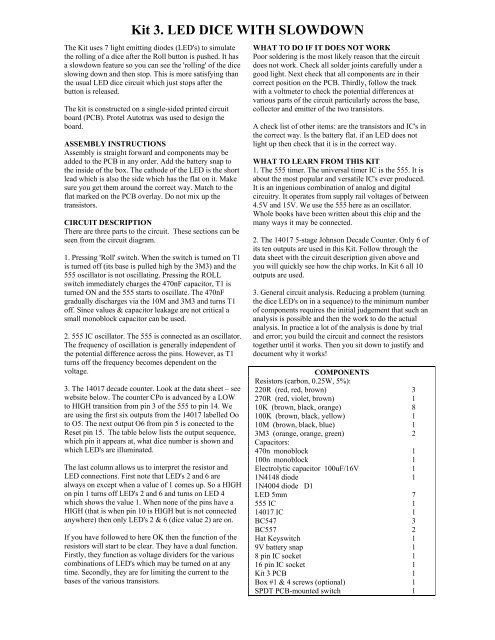
<strong>Kit</strong> <strong>3.</strong> <strong>LED</strong> <strong>DICE</strong> <strong>WITH</strong> <strong>SLOWDOWN</strong><br />
The <strong>Kit</strong> uses 7 light emitting diodes (<strong>LED</strong>'s) to simulate<br />
the rolling of a dice after the Roll button is pushed. It has<br />
a slowdown feature so you can see the 'rolling' of the dice<br />
slowing down and then stop. This is more satisfying than<br />
the usual <strong>LED</strong> dice circuit which just stops after the<br />
button is released.<br />
The kit is constructed on a single-sided printed circuit<br />
board (PCB). Protel Autotrax was used to design the<br />
board.<br />
ASSEMBLY INSTRUCTIONS<br />
Assembly is straight forward and components may be<br />
added to the PCB in any order. Add the battery snap to<br />
the inside of the box. The cathode of the <strong>LED</strong> is the short<br />
lead which is also the side which has the flat on it. Make<br />
sure you get them around the correct way. Match to the<br />
flat marked on the PCB overlay. Do not mix up the<br />
transistors.<br />
CIRCUIT DESCRIPTION<br />
There are three parts to the circuit. These sections can be<br />
seen from the circuit diagram.<br />
1. Pressing 'Roll' switch. When the switch is turned on T1<br />
is turned off (its base is pulled high by the 3M3) and the<br />
555 oscillator is not oscillating. Pressing the ROLL<br />
switch immediately charges the 470nF capacitor, T1 is<br />
turned ON and the 555 starts to oscillate. The 470nF<br />
gradually discharges via the 10M and 3M3 and turns T1<br />
off. Since values & capacitor leakage are not critical a<br />
small monoblock capacitor can be used.<br />
2. 555 IC oscillator. The 555 is connected as an oscillator.<br />
The frequency of oscillation is generally independent of<br />
the potential difference across the pins. However, as T1<br />
turns off the frequency becomes dependent on the<br />
voltage.<br />
<strong>3.</strong> The 14017 decade counter. Look at the data sheet – see<br />
website below. The counter CPo is advanced by a LOW<br />
to HIGH transition from pin 3 of the 555 to pin 14. We<br />
are using the first six outputs from the 14017 labelled Oo<br />
to O5. The next output O6 from pin 5 is conected to the<br />
Reset pin 15. The table below lists the output sequence,<br />
which pin it appears at, what dice number is shown and<br />
which <strong>LED</strong>'s are illuminated.<br />
The last column allows us to interpret the resistor and<br />
<strong>LED</strong> connections. First note that <strong>LED</strong>'s 2 and 6 are<br />
always on except when a value of 1 comes up. So a HIGH<br />
on pin 1 turns off <strong>LED</strong>'s 2 and 6 and turns on <strong>LED</strong> 4<br />
which shows the value 1. When none of the pins have a<br />
HIGH (that is when pin 10 is HIGH but is not connected<br />
anywhere) then only <strong>LED</strong>'s 2 & 6 (dice value 2) are on.<br />
If you have followed to here OK then the function of the<br />
resistors will start to be clear. They have a dual function.<br />
Firstly, they function as voltage dividers for the various<br />
combinations of <strong>LED</strong>'s which may be turned on at any<br />
time. Secondly, they are for limiting the current to the<br />
bases of the various transistors.<br />
WHAT TO DO IF IT DOES NOT WORK<br />
Poor soldering is the most likely reason that the circuit<br />
does not work. Check all solder joints carefully under a<br />
good light. Next check that all components are in their<br />
correct position on the PCB. Thirdly, follow the track<br />
with a voltmeter to check the potential differences at<br />
various parts of the circuit particularly across the base,<br />
collector and emitter of the two transistors.<br />
A check list of other items: are the transistors and IC's in<br />
the correct way. Is the battery flat. if an <strong>LED</strong> does not<br />
light up then check that it is in the correct way.<br />
WHAT TO LEARN FROM THIS KIT<br />
1. The 555 timer. The universal timer IC is the 555. It is<br />
about the most popular and versatile IC's ever produced.<br />
It is an ingenious combination of analog and digital<br />
circuitry. It operates from supply rail voltages of between<br />
4.5V and 15V. We use the 555 here as an oscillator.<br />
Whole books have been written about this chip and the<br />
many ways it may be connected.<br />
2. The 14017 5-stage Johnson Decade Counter. Only 6 of<br />
its ten outputs are used in this <strong>Kit</strong>. Follow through the<br />
data sheet with the circuit description given above and<br />
you will quickly see how the chip works. In <strong>Kit</strong> 6 all 10<br />
outputs are used.<br />
<strong>3.</strong> General circuit analysis. Reducing a problem (turning<br />
the dice <strong>LED</strong>'s on in a sequence) to the minimum number<br />
of components requires the initial judgement that such an<br />
analysis is possible and then the work to do the actual<br />
analysis. In practice a lot of the analysis is done by trial<br />
and error; you build the circuit and connect the resistors<br />
together until it works. Then you sit down to justify and<br />
document why it works!<br />
COMPONENTS<br />
Resistors (carbon, 0.25W, 5%):<br />
220R (red, red, brown) 3<br />
270R (red, violet, brown) 1<br />
10K (brown, black, orange) 8<br />
100K (brown, black, yellow) 1<br />
10M (brown, black, blue) 1<br />
3M3 (orange, orange, green) 2<br />
Capacitors:<br />
470n monoblock 1<br />
100n monoblock 1<br />
Electrolytic capacitor 100uF/16V 1<br />
1N4148 diode 1<br />
1N4004 diode D1<br />
<strong>LED</strong> 5mm 7<br />
555 IC 1<br />
14017 IC 1<br />
BC547 3<br />
BC557 2<br />
Hat Keyswitch 1<br />
9V battery snap 1<br />
8 pin IC socket 1<br />
16 pin IC socket 1<br />
<strong>Kit</strong> 3 PCB 1<br />
Box #1 & 4 screws (optional) 1<br />
SPDT PCB-mounted switch 1
<strong>Kit</strong> <strong>3.</strong> <strong>LED</strong> <strong>DICE</strong> <strong>WITH</strong> <strong>SLOWDOWN</strong><br />
14017 Output 14017 pin Dice <strong>LED</strong>’s on (See circuit<br />
high sequence number Number diagram for reference)<br />
1 3 4 1 2 6 7<br />
2 2 3 2 4 6<br />
3 4 6 1 2 3 5 6 7<br />
4 7 5 1 2 4 6 7<br />
5 10 2 2 6<br />
6 1 1 4<br />
7 reset 5 to 15<br />
For the data sheet and an excellent introduction to the 14017 chip see<br />
http://www.doctronics.co.uk/4017.htm<br />
Google LM555 will bring up tens of websites on it.