A Rolling Code 4-channel UHF Remote Control - Kitsrus
A Rolling Code 4-channel UHF Remote Control - Kitsrus
A Rolling Code 4-channel UHF Remote Control - Kitsrus

Create successful ePaper yourself
Turn your PDF publications into a flip-book with our unique Google optimized e-Paper software.
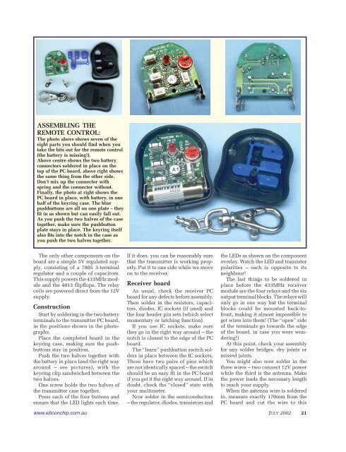
ASSEMBLING THE<br />
REMOTE CONTROL:<br />
The photo above shows seven of the<br />
eight parts you should find when you<br />
take the bits out for the remote control<br />
(the battery is missing!).<br />
Above centre shows the two battery<br />
connectors soldered in place on the<br />
top of the PC board, above right shows<br />
the same thing from the other side.<br />
Don’t mix up the connector with<br />
spring and the connector without.<br />
Finally, the photo at right shows the<br />
PC board in place, with battery, in one<br />
half of the keyring case. The blue<br />
pushbuttons are all on one plate – they<br />
fit in as shown but can easily fall out.<br />
As you push the two halves of the case<br />
together, make sure the pushbutton<br />
plate stays in place. The keyring itself<br />
also fits into the notch in the case as<br />
you push the two halves together.<br />
The only other components on the<br />
board are a simple 5V regulated supply,<br />
consisting of a 7805 3-terminal<br />
regulator and a couple of capacitors.<br />
This supply powers the 433MHz module<br />
and the 4013 flipflops. The relay<br />
coils are powered direct from the 12V<br />
supply.<br />
Construction<br />
Start by soldering in the two battery<br />
terminals to the transmitter PC board,<br />
in the positions shown in the photographs.<br />
Place the completed board in the<br />
keyring case, making sure the pushbuttons<br />
stay in position.<br />
Push the two halves together with<br />
the battery in place (and the right way<br />
around – see pictures), with the<br />
keyring clip sandwiched between the<br />
two halves.<br />
One screw holds the two halves of<br />
the transmitter case together.<br />
Press each of the four buttons and<br />
ensure that the LED lights each time.<br />
www.siliconchip.com.au<br />
If it does, you can be reasonably sure<br />
that the transmitter is working properly.<br />
Put it to one side while we move<br />
on to the receiver.<br />
Receiver board<br />
As usual, check the receiver PC<br />
board for any defects before assembly.<br />
Then solder in the resistors, capacitors,<br />
diodes, IC sockets (if used) and<br />
the four header pin sets (which select<br />
momentary or latching function).<br />
If you use IC sockets, make sure<br />
they go in the right way around – the<br />
notch is closest to the edge of the PC<br />
board.<br />
The “learn” pushbutton switch solders<br />
in place between the IC sockets.<br />
These have two pairs of pins which<br />
are not identically spaced – the switch<br />
should be an easy fit in the PC board<br />
if you get it the right way around. If in<br />
doubt, check the “closed” state with<br />
your multimeter.<br />
Now solder in the semiconductors<br />
– the regulator, diodes, transistors and<br />
the LEDs as shown on the component<br />
overlay. Watch the LED and transistor<br />
polarities – each is opposite to its<br />
neighbour!<br />
The last things to be soldered in<br />
place before the 433MHz receiver<br />
module are the four relays and the six<br />
output terminal blocks. The relays will<br />
only go in one way but the terminal<br />
blocks could be mounted back-tofront,<br />
making it almost impossible to<br />
get wires into them! (The “open” side<br />
of the terminals go towards the edge<br />
of the board, in case you were wondering!)<br />
At this point, check your assembly<br />
for any solder bridges, dry joints or<br />
missed joints.<br />
You might also now solder in the<br />
three wires – two connect 12V power<br />
while the third is the antenna. Make<br />
the power leads the necessary length<br />
to reach your supply.<br />
When the antenna wire is soldered<br />
in, measure exactly 170mm from the<br />
PC board and cut the wire to this<br />
JULY 2002 21