A Rolling Code 4-channel UHF Remote Control - Kitsrus
A Rolling Code 4-channel UHF Remote Control - Kitsrus
A Rolling Code 4-channel UHF Remote Control - Kitsrus

Create successful ePaper yourself
Turn your PDF publications into a flip-book with our unique Google optimized e-Paper software.
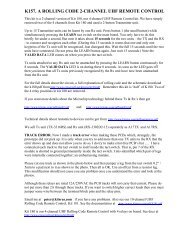
The nearest thing you can get to “unbreakable” . . .<br />
A <strong>Rolling</strong> <strong>Code</strong><br />
4-<strong>channel</strong> <strong>UHF</strong><br />
<strong>Remote</strong> <strong>Control</strong><br />
This is one very clever remote control. With rolling code, it’s close-toimpossible<br />
to electronically “crack”. With four <strong>channel</strong>s, all either<br />
latching or momentary operation, it’s extremely versatile. With a<br />
sensitive prebuilt receiver, it’s long range. With up-to-16 keyring-size<br />
transmitters, it’s go-anywhere. And the kit even includes the keyring!<br />
By Ross Tester<br />
Whether you want to<br />
control a garage door or<br />
gate, a car and/or home<br />
alarm, or perhaps<br />
remotely turn lights or<br />
anything else on or off,<br />
this high-security<br />
system is just what<br />
you’re looking for!<br />
Inset top right are the<br />
pre-built, aligned and<br />
tested receiver (top) and<br />
transmitter (bottom)<br />
modules, shown here<br />
same-size.<br />
18 SILICON CHIP www.siliconchip.com.au
We’ve presented a number of<br />
remote (radio) control devices<br />
in the past. None has<br />
been more secure than this one. To<br />
guess the code combination, you’re<br />
going to need something like 23 billion<br />
years. But don’t bother: the next<br />
time it’s used, the code will have<br />
changed anyway.<br />
That’s the advantage of a rolling<br />
code (or “code hopping”) system. We<br />
explain what this means, and does,<br />
later in this article.<br />
Suffice to say at this stage that it<br />
makes one v-e-r-y secure system. For<br />
all intents and purposes, it is impossible<br />
to electronically “crack”. Go on,<br />
give it a go – we’ll see you in a few<br />
million years or so!<br />
The transmitter<br />
It’s probably not necessary to say it<br />
but there are two parts to this project,<br />
a transmitter and a receiver.<br />
First of all, there is<br />
the tiny 4-<strong>channel</strong><br />
“key-ring” transmitter<br />
which, fortunately,<br />
comes 99% preassembled.<br />
We say fortunately<br />
because it’s just<br />
about all SMD (surface<br />
mount devices)<br />
which, while not<br />
impossible for the<br />
hobbyist to work<br />
with, requires some<br />
rather special handling.<br />
You are<br />
spared that!<br />
All you have to<br />
do with the transmitter<br />
PC board is<br />
solder on the two<br />
battery connectors<br />
and place it in the case (with battery).<br />
The battery contacts are slightly different:<br />
the one with a spring is for the<br />
negative battery connection – it goes<br />
on the righthand side of the PC board<br />
with the only straight side of the PC<br />
board at the bottom.<br />
You may find, as we did, that some<br />
of the holes for the battery connectors<br />
are filled with solder. This is easily<br />
melted during installation.<br />
Once this is done, it’s just a matter of<br />
assembling the board in its keyring case.<br />
Incidentally, the keyring case and battery<br />
are all supplied in the kit.<br />
The transmitter itself is in the licence-free<br />
433MHz LIPD band (it’s<br />
SPECIFICATIONS<br />
• <strong>UHF</strong> (433MHz) licence-free (LIPD band) operation<br />
• Long range – prototype tested to 100m+<br />
• Pre-built and aligned transmitter & receiver modules<br />
• <strong>Rolling</strong>-code (“code hopping”) operation (7.3 x 10 19 codes)<br />
• Receiver “learns” transmitter coding<br />
• Receiver can handle up to 16 remotes<br />
• Transmitter can handle any number of receivers<br />
• 4 <strong>channel</strong>s available, each either momentary (push on, release<br />
off) or latching (push on, push off) via jumpers<br />
• <strong>Code</strong> acknowledge LED and <strong>channel</strong> status LEDs<br />
• Each <strong>channel</strong> relay contacts rated at 28VDC/12A (single pole,<br />
changeover)<br />
actually on 433.9MHz). As with most<br />
devices of this type these days, it is<br />
based on a SAW resonator (that stands<br />
for surface acoustic wave, so now you<br />
know!). This keeps the circuit very<br />
simple but enables excellent performance.<br />
Without wanting to get into the<br />
nitty-gritty of SAW resonator operation,<br />
in essence it controls the RF side<br />
of things while a dedicated chip controls<br />
the complex digital coding.<br />
The receiver (which we’ll get to<br />
shortly) can handle up to 16 transmitters<br />
so if you have a really big family<br />
or maybe have a secure company<br />
carpark you want to give a certain<br />
number of people access to, you can<br />
do so simply by purchasing more<br />
transmitters.<br />
The transmitter has four pushbuttons,<br />
one for each of the four <strong>channel</strong>s.<br />
Of course you don’t have to use all<br />
four <strong>channel</strong>s – just one will control<br />
• 12V DC operation (6mA quiescent; 150mA all relays actuated)<br />
most garage door openers, for example<br />
– but it’s nice to know there are<br />
four <strong>channel</strong>s available.<br />
And before we move off the transmitter,<br />
up to three <strong>channel</strong>s can be<br />
pressed simultaneously and the receiver<br />
will react to all three (it won’t<br />
handle four at once, though).<br />
Finally, as well as multiple transmitters,<br />
you can use more than one<br />
receiver if you wish.<br />
Each receiver “learns” its transmitter(s)<br />
so you can have a multiple<br />
system controlling, for example, the<br />
garage door, the car doors, the car<br />
alarm, the home security system – in<br />
fact, anything your little heart desires.<br />
The receiver/decoder<br />
Now we move on to the heart of the<br />
system, at least the bits you have to<br />
put together to make it work.<br />
In fact, there are two parts to the<br />
receiver as well. There is a 433MHz<br />
receiver module which comes assembled,<br />
aligned and ready to go. This<br />
solders into an appropriate set of holes<br />
on the main PC board once you’ve<br />
finished assembling that board.<br />
The main PC board contains the<br />
electronics which process the output<br />
from the receiver.<br />
The receiver checks the incoming<br />
code and if valid, sends a signal to one<br />
of four outputs depending on which<br />
button was pressed on the transmitter).<br />
From here, depending on how the<br />
four jumpers are set on the board, the<br />
signal goes either direct to an NPN<br />
transistor relay driver (for momentary<br />
operation – the relay is energised while<br />
the button remains<br />
pressed) or to a D-<br />
type flipflop and<br />
then to the transistor<br />
relay driver (for<br />
alternate operation –<br />
press once and the<br />
relay latches, press<br />
again and the relay<br />
releases).<br />
The flipflops<br />
change state (toggle)<br />
each time a postive<br />
going pulse appears<br />
at the clock input.<br />
This is achieved by<br />
the connection from<br />
the Q-bar output to<br />
the D input via an RC<br />
network.<br />
The circuit has a<br />
power-up reset. When<br />
power is first applied,<br />
the Q outputs of the flipflops are reset<br />
low by the 0.1µF capacitor and 1MΩ<br />
resistor on the reset (S) inputs.<br />
Reset is caused by sending the reset<br />
inputs of all flipflops high. Once the<br />
capacitor is charged, the voltage at the<br />
reset inputs of the flipflops falls to<br />
virtually zero, allowing normal operation<br />
It is perfectly acceptable to have a<br />
mixture of momentary and latched<br />
modes amongst the four <strong>channel</strong>s. It’s<br />
up to you.<br />
But if you only require momentary<br />
action (for example, as needed by<br />
www.siliconchip.com.au<br />
JULY 2002 19
IC1, IC2: 4013<br />
D1- D4: 1N4004<br />
ANTENNA<br />
170mm<br />
TEST<br />
POINT<br />
PB1<br />
11<br />
4<br />
7<br />
LEARN<br />
3<br />
10<br />
9<br />
433MHz<br />
RECEIVER 8<br />
MODULE<br />
6<br />
12 5<br />
1k<br />
A<br />
LED5<br />
K<br />
IC1 PIN14,<br />
IC2 PIN14<br />
0.1 <br />
F<br />
0.1 <br />
F<br />
0.1 <br />
F<br />
0.1 <br />
F<br />
10M<br />
5<br />
D<br />
S<br />
Q<br />
IC1a<br />
3<br />
CLK Q<br />
R<br />
6<br />
10M<br />
10<br />
9<br />
D<br />
S<br />
Q<br />
IC1b<br />
6<br />
CLK Q<br />
R<br />
8<br />
10M<br />
4<br />
5<br />
D<br />
S<br />
Q<br />
IC2a<br />
3<br />
CLK Q<br />
R<br />
6<br />
10M<br />
4<br />
10<br />
9<br />
D<br />
S<br />
Q<br />
IC2b<br />
6<br />
CLK Q<br />
R<br />
8<br />
1<br />
2<br />
13<br />
12<br />
1<br />
2<br />
13<br />
12<br />
J1<br />
J2<br />
J3<br />
J4<br />
0.1 <br />
F<br />
2.2k<br />
+5V +12V<br />
LED1<br />
LED2<br />
LED3<br />
LED4<br />
4.7k<br />
4.7k<br />
4.7k<br />
4.7k<br />
<br />
<br />
<br />
<br />
B<br />
D1<br />
2.2k<br />
D2<br />
B<br />
2.2k<br />
D3<br />
B<br />
2.2k<br />
D4<br />
B<br />
K<br />
A<br />
C<br />
Q1<br />
C8050<br />
E<br />
K<br />
A<br />
C<br />
Q2<br />
C8050<br />
E<br />
K<br />
A<br />
C<br />
Q3<br />
C8050<br />
E<br />
K<br />
A<br />
C<br />
Q4<br />
C8050<br />
E<br />
RELAY1<br />
RELAY2<br />
RELAY3<br />
RELAY4<br />
+12V<br />
+12V<br />
+12V<br />
NC<br />
COM<br />
NO<br />
NC<br />
COM<br />
NO<br />
NC<br />
COM<br />
NO<br />
NC<br />
COM<br />
NO<br />
+12V<br />
1M<br />
+12V<br />
REG1 7805<br />
IN OUT<br />
+5V<br />
7805<br />
Q1- Q4<br />
C8050<br />
LEDS<br />
0.1 <br />
F<br />
100 <br />
F<br />
COM<br />
100 <br />
F<br />
0.1 <br />
F<br />
K<br />
GND<br />
IC1 PIN7,<br />
IC2 PIN7<br />
IN<br />
GND<br />
OUT<br />
C B E<br />
D1-4<br />
A K<br />
A<br />
SC<br />
2002<br />
4-CHANNEL <strong>UHF</strong> “rolling code” REMOTE CONTROL RECEIVER<br />
Fig.1: the circuit of the “control” section of the receiver unit. We haven’t attempted to show the 433MHz receiver itself, nor<br />
the transmitter, as these are both pre-assembled modules, saving you a lot of difficult work!<br />
some door openers/closers) the flipflops,<br />
along with their associated RC<br />
network components and the four<br />
header pin jumper sets, could be left<br />
out of circuit. (You’d then need four<br />
links on the PC board to directly connect<br />
the receiver outputs to their respective<br />
transistors.)<br />
Along with spike suppression diodes<br />
across each relay coil, part of<br />
each relay driver circuit also includes<br />
an acknowledge LED to give a visible<br />
output of what’s happening.<br />
There is also a “valid signal acknowledge”<br />
LED attached to the<br />
433MHz module, which lights when<br />
valid code is being received.<br />
Each of the four identical relays has<br />
contacts rated at 28VDC & 12A, so can<br />
be used to control significant loads.<br />
The wide track widths on the PC board<br />
also allow high currents.<br />
The relay contacts could, of course,<br />
also be used to switch higher-rated<br />
relays or you could replace the acknowledge<br />
LED with an opto-coupler.<br />
The relays themselves are single<br />
pole but have normally open (NO)<br />
and normally closed (NC) contacts.<br />
These states refer to the unenergised<br />
state of the relay (ie, the NC contacts<br />
go open when power is applied to the<br />
relay coil and vice-versa).<br />
20 SILICON CHIP www.siliconchip.com.au
ASSEMBLING THE<br />
REMOTE CONTROL:<br />
The photo above shows seven of the<br />
eight parts you should find when you<br />
take the bits out for the remote control<br />
(the battery is missing!).<br />
Above centre shows the two battery<br />
connectors soldered in place on the<br />
top of the PC board, above right shows<br />
the same thing from the other side.<br />
Don’t mix up the connector with<br />
spring and the connector without.<br />
Finally, the photo at right shows the<br />
PC board in place, with battery, in one<br />
half of the keyring case. The blue<br />
pushbuttons are all on one plate – they<br />
fit in as shown but can easily fall out.<br />
As you push the two halves of the case<br />
together, make sure the pushbutton<br />
plate stays in place. The keyring itself<br />
also fits into the notch in the case as<br />
you push the two halves together.<br />
The only other components on the<br />
board are a simple 5V regulated supply,<br />
consisting of a 7805 3-terminal<br />
regulator and a couple of capacitors.<br />
This supply powers the 433MHz module<br />
and the 4013 flipflops. The relay<br />
coils are powered direct from the 12V<br />
supply.<br />
Construction<br />
Start by soldering in the two battery<br />
terminals to the transmitter PC board,<br />
in the positions shown in the photographs.<br />
Place the completed board in the<br />
keyring case, making sure the pushbuttons<br />
stay in position.<br />
Push the two halves together with<br />
the battery in place (and the right way<br />
around – see pictures), with the<br />
keyring clip sandwiched between the<br />
two halves.<br />
One screw holds the two halves of<br />
the transmitter case together.<br />
Press each of the four buttons and<br />
ensure that the LED lights each time.<br />
www.siliconchip.com.au<br />
If it does, you can be reasonably sure<br />
that the transmitter is working properly.<br />
Put it to one side while we move<br />
on to the receiver.<br />
Receiver board<br />
As usual, check the receiver PC<br />
board for any defects before assembly.<br />
Then solder in the resistors, capacitors,<br />
diodes, IC sockets (if used) and<br />
the four header pin sets (which select<br />
momentary or latching function).<br />
If you use IC sockets, make sure<br />
they go in the right way around – the<br />
notch is closest to the edge of the PC<br />
board.<br />
The “learn” pushbutton switch solders<br />
in place between the IC sockets.<br />
These have two pairs of pins which<br />
are not identically spaced – the switch<br />
should be an easy fit in the PC board<br />
if you get it the right way around. If in<br />
doubt, check the “closed” state with<br />
your multimeter.<br />
Now solder in the semiconductors<br />
– the regulator, diodes, transistors and<br />
the LEDs as shown on the component<br />
overlay. Watch the LED and transistor<br />
polarities – each is opposite to its<br />
neighbour!<br />
The last things to be soldered in<br />
place before the 433MHz receiver<br />
module are the four relays and the six<br />
output terminal blocks. The relays will<br />
only go in one way but the terminal<br />
blocks could be mounted back-tofront,<br />
making it almost impossible to<br />
get wires into them! (The “open” side<br />
of the terminals go towards the edge<br />
of the board, in case you were wondering!)<br />
At this point, check your assembly<br />
for any solder bridges, dry joints or<br />
missed joints.<br />
You might also now solder in the<br />
three wires – two connect 12V power<br />
while the third is the antenna. Make<br />
the power leads the necessary length<br />
to reach your supply.<br />
When the antenna wire is soldered<br />
in, measure exactly 170mm from the<br />
PC board and cut the wire to this<br />
JULY 2002 21
VALID<br />
DATA<br />
ANT<br />
REG1 7805<br />
LED5<br />
100 <br />
F<br />
+<br />
1k<br />
TP<br />
433MHz RECEIVER MODULE<br />
D3 NC LA VT +5V GND<br />
D2 D1 D0 TP DOUT<br />
ANT<br />
GND<br />
TX1<br />
0.1 <br />
F<br />
1<br />
L<br />
L<br />
L<br />
0.1 F<br />
L<br />
+<br />
GND +12V<br />
0.1 <br />
F<br />
100 <br />
F<br />
M<br />
J1<br />
10M<br />
IC1 4013<br />
10M<br />
J2<br />
M<br />
M<br />
J3<br />
10M<br />
IC2 4013<br />
10M<br />
J4<br />
M<br />
1M<br />
4.7k<br />
0.1 F<br />
0.1 F<br />
Q2 Q1<br />
4.7k<br />
PB1<br />
LEARN<br />
0.1 F<br />
0.1 F<br />
Q4 Q3<br />
length. This makes it resonant at<br />
433MHz.<br />
You should not have any bare<br />
wire(s) emerging from the end of the<br />
antenna – this could short onto something<br />
nasty and do you/it/something<br />
else some damage! If necessary, wrap<br />
a little insulation tape around the end<br />
of the antenna wire – just in case!<br />
Plug the two ICs into their sockets,<br />
again watching the polarity. The<br />
notches should line up with the<br />
notches in the sockets (assuming you<br />
got the sockets right!)<br />
OK, we’re almost there. Place the<br />
receiver module in its appropriate<br />
holes along the edge of the PC board.<br />
It will only go one way (incidentally,<br />
take care not to move the coil or touch<br />
the trimmer capacitor).<br />
Solder each of the module pins into<br />
position (there are 13 of them – don’t<br />
forget the two by themselves) and your<br />
receiver is finished.<br />
Power supply<br />
The receiver unit is designed for<br />
12V battery operation and power requirements<br />
are pretty modest. At rest,<br />
(ie, no relays operating), it draws only<br />
6mA and even with all relays actuated,<br />
the current is just a smidgeon<br />
under 150mA.<br />
Therefore, most alarm-type batteries<br />
(eg, SLAs) will be more than adequate.<br />
We had it operating for a couple of<br />
weeks on a 7Ah 12V gell cell, periodically<br />
pressing the remote control just<br />
for the hell of it, without recharging<br />
the battery. In fact, at the end of this<br />
1<br />
2.2k<br />
C8050<br />
LED1<br />
LED2<br />
2.2k<br />
D2<br />
D3<br />
C8050<br />
D1<br />
4.7k<br />
2.2k<br />
LED3<br />
LED4<br />
2.2k<br />
4.7k<br />
D4<br />
RELAY4 RELAY3 RELAY2 RELAY1<br />
Fig.2 (above): the<br />
component overlay<br />
of the receiver<br />
module with the<br />
full-size<br />
photograph at<br />
right. Just to<br />
confuse you, we’ve<br />
shown the board<br />
turned 180°<br />
compared to the<br />
diagram above!<br />
22 SILICON CHIP www.siliconchip.com.au<br />
NC<br />
COM<br />
NO<br />
NC<br />
COM<br />
NO<br />
NC<br />
COM<br />
NO<br />
NC<br />
COM<br />
NO<br />
time the battery voltage changed only<br />
a few tens of millivolts – probably not<br />
much more than you would expect<br />
during shelf life.<br />
Therefore, just about any 12V battery<br />
would be acceptable, even a couple<br />
of 6V lantern batteries in series or<br />
even 10 C or D-size Nicads.<br />
Of course, you could also use just<br />
about any garden-variety 12V or 13.8V<br />
DC (nominal) plug-pack supply.<br />
The relays won’t worry about a few<br />
extra volts and the circuit has the onboard<br />
5V regulator to ensure the electronics<br />
get the right voltage. Any DC<br />
plugpack over about 200mA capacity<br />
should be fine.<br />
Learning and testing<br />
Looking at the board with the outputs/relays<br />
on the left side, move all<br />
header pins to the right side (latching).<br />
Apply power and you should see<br />
absolutely nothing happen. So far, so<br />
good.<br />
Now press the “learn” button once,<br />
then within 15 seconds press button<br />
one on the keyring transmitter for a<br />
second or so. Button one is the one all<br />
by itself on one side of the transmitter.<br />
The receiver then learns the encryption<br />
from the keyring transmitter –<br />
and remembers it.<br />
Now all four buttons on your transmitter<br />
should alternately close and<br />
open the appropriate relay and light/<br />
switch off its associated LED.<br />
Change the four jumpers over to the<br />
opposite way and all four buttons<br />
should now pull in a relay and light a<br />
LED while ever they are pressed – and<br />
release it/dim it when let go.<br />
And that’s just about it. Now all you<br />
have to do is select the jumpers the<br />
way you want them and connect the<br />
external devices you wish to control.<br />
Note that each relay has a normally<br />
open and normally closed connection<br />
as well as common, so you have a lot<br />
of flexibility at your disposal.<br />
Want even more security?<br />
We mentioned before the one major<br />
drawback with any remotely controlled<br />
security application, whether that
What is “<strong>Code</strong> Hopping” or “<strong>Rolling</strong> <strong>Code</strong>”<br />
These two names usually refer to the same thing – in a nutshell,<br />
a security system for a security system.<br />
It’s a way of preventing unauthorised access to a digital code<br />
which might be transmitted via a short-range radio link to do<br />
something: open a garage door, lock or unlock a car and perhaps<br />
turn its own security system on and off – and much more.<br />
But before we look at these terms, though, let’s go back in time<br />
to the days before code hopping and rolling code.<br />
Short-range radio-operated control devices have been around<br />
for a couple of decades or so (at least, in any volume). The earliest<br />
ones that I remember simply used a burst of RF, at a particular<br />
frequency, with an appropriate receiver.<br />
It’s not hard to see the shortcomings of such devices. Simply<br />
sweeping the likely band(s) with an RF generator attached to an<br />
antenna would more often than not achieve the desired result<br />
(desired for the intruder, that is).<br />
It didn’t take long for crooks to latch on to this one (do you like<br />
that metaphor?). So manufacturers decided to make it a bit harder<br />
for them by modulating the RF at a frequency (or indeed multiple<br />
frequencies in some cases) “known” to the receiver.<br />
Some used the standard DTMF tones generated by phone<br />
keypads because they were very cheap and made in the millions.<br />
“Oh, gee,” said the crooks. Now we’ll have to use an RF<br />
oscillator with a modulator. Or maybe even a DTMF keypad!”<br />
Duh! (Still, it probably seemed like a good idea at the time. . .)<br />
Ever one step ahead, the manufacturers went with this (then)<br />
new-fangled digital stuff and made each transmitter send a particular<br />
code which was matched to the receiver. This was usually<br />
done by way of DIP switches in both transmitter and receiver.<br />
With eight DIP switches (probably the most common because<br />
8-way DIP switches were common!), you would have 2 8 or 256<br />
codes available. So you and your next-door neighbour could have<br />
the same type of garage door opener on the same frequency and<br />
the odds would be pretty good that their door would stay down<br />
when you pressed your button.<br />
The problem with this, though, is that the transmitter spurted<br />
out exactly the same code every time (unless, of course, both sets<br />
of dip switches were changed). Enter the crooks again.<br />
With a suitable receiver, called a “code grabber”, if they got<br />
within a few tens of metres of you they could scan for the RF signal<br />
and record your code without you knowing anything about it (for<br />
example, as you left your car in a carpark and pressed the button<br />
on your remote to lock the doors and turn on the alarm).<br />
Once you’d gone, they simply “played it back” using the same<br />
code grabber. Presto, one missing car. Or one house burgled, etc<br />
etc.<br />
Even without a code grabber, a smart intruder with the right<br />
equipment using digital techniques and trying eight combinations<br />
per second, could crack the code in no more than 32 seconds –<br />
and probably much quicker.<br />
It’s hard to believe the gall of some organisations openly<br />
flogging such devices, euphemistically disguising them (justifying<br />
them?) with names such as vehicle lockout recovery systems or<br />
disabled vehicle recovery systems. Then again, lock picks are sold<br />
for professional locksmiths, aren’t they?<br />
Now we move on a little. Microchip, the same people who<br />
brought you those ubiquitous PICs, invented a system called<br />
KEELOQ – better known to you and me as a rolling code.<br />
What this does is simply present a different code every time the<br />
transmitter button is pressed. Of course, that’s the easy part. The<br />
really clever part is that the receiver “learns” the algorithm which<br />
controls the code so it knows what code to expect. Once learnt, the<br />
receiver is effectively “locked” to that transmitter.<br />
Actually, it’s even cleverer than that, because the transmitted<br />
code is, for all intents and purposes, random (as far as any<br />
external device is concerned). But the receiver can still work out<br />
what the code is going to be in advance. If it gets the right code, it<br />
actuates. If not – you’re out in the cold, baby!<br />
The chances of the same code being transmitted twice in a<br />
person’s lifetime is possible – but remote (at four transmissions<br />
per day, every day, it’s reckoned to be about 44 years!)<br />
Heart of this system is a Microchip proprietary IC, the HC301. It<br />
combines a 32-bit hopping code generated by a nonlinear<br />
encryption algorithm with a 28-bit serial number and six information<br />
bits to create a 66-bit code word. The code word length<br />
eliminates the threat of code scanning and the code-hopping<br />
mechanism makes each transmission unique, rendering code<br />
capture and resend techniques useless.<br />
Even if it didn’t code-hop, 66 bits allows 7.3 x 10 19 combinations,<br />
which according to Microchip would only take<br />
230,000,000,000 years to scan!<br />
The chip itself is also protected against intrusion. Several<br />
important data are stored in an EEPROM array which is not<br />
accessible via any external connection. These include the crypt<br />
key, a unique and secret 64-bit number used to encrypt and<br />
decrypt data, the serial number and the configuration data.<br />
The EEPROM data is programmable but read-protected. It can<br />
be verified only after an automatic erase and programming operation,<br />
protecting against attempts to gain access to keys or to<br />
manipulate synchronisation values.<br />
If the code is changed every time a button is pressed on the<br />
transmitter, what happens if, say a child starts playing with the<br />
remote control and continually presses buttons away from the<br />
receiver? OK, here’s where it gets really clever (and you thought it<br />
was clever enough already, didn’t you?).<br />
If the button is pressed say 10 times while out of range of the<br />
receiver, no problem. But if it is pressed more than 16 times,<br />
synchronisation between the two is lost. However, it only takes<br />
two presses of a button in range to restore sync. No, we don’t<br />
know how either. That’s Microchip’s secret!<br />
And speaking of button presses, there are a couple of other<br />
clever things they’ve done. At most, a complete code will take<br />
100ms to send (it could be as low as 25ms). But if you manage to<br />
hit the button and release it before 100ms (difficult, but possible),<br />
it will keep sending that complete code. If you hold down the<br />
button, it will keep sending that same code. And if you press<br />
another button while the first is held down, it will abort the first and<br />
send the second.<br />
As you can see, KEELOQ is a very robust system. Sure, it’s not<br />
absolutely foolproof – nothing is (eg, there’s not much protection<br />
if they simply steal your transmitter!). But for most users, it gives<br />
almost total peace-of-mind. That’s why the system has been<br />
adopted by so many vehicle entry/exit and alarm system manufacturers,<br />
access controllers and so on.<br />
And that’s the system that’s used in the remote control unit<br />
presented here.<br />
www.siliconchip.com.au<br />
JULY 2002 23
e for a car, a building or anything<br />
else: what happens if someone pinches<br />
your remote control?<br />
It is possible to protect yourself<br />
against the casual button pusher on a<br />
stolen control – at least to some degree.<br />
Having four <strong>channel</strong>s at your disposal,<br />
in this remote control system,<br />
gives you the possibility of increasing<br />
security rather significantly, simply<br />
by using a combination of keys on<br />
your remote.<br />
It is “normal” to use one button to<br />
achieve a certain function. But what if<br />
you used two buttons? It’s possible<br />
because when you press the second<br />
button, even while holding down the<br />
RELAY<br />
1<br />
C<br />
NO<br />
NC<br />
CIRCUIT<br />
TO BE<br />
SWITCHED<br />
CIRCUIT<br />
TO BE<br />
SWITCHED<br />
RELAY<br />
1<br />
C<br />
C<br />
RELAY<br />
2<br />
Fig.3a (left): conventional device<br />
control with one relay. Adding a<br />
second relay in series (fig 3b, right)<br />
increases security against the casual<br />
button pusher. Both buttons must be<br />
pressed at the same time for the<br />
device to actuate.<br />
NO<br />
NC<br />
NO<br />
NC<br />
Parts List –<br />
4-Channel <strong>Code</strong>-Hopping <strong>Remote</strong> <strong>Control</strong><br />
1 TX-4312RSA 4-<strong>channel</strong> keyring rolling code transmitter assembly<br />
1 RX3302D A1.5 433MHz rolling code receiver module<br />
1 PC board, coded K180, 86 x 78mm<br />
4 miniature relays, SPDT, PCB mounting, 12V coils (Millionspot H5000xx)<br />
1 ultramini pushbutton switch, PC mounting, N-O contacts<br />
6 interlocking 2-way terminal blocks, PC mounting<br />
2 14-pin DIL IC sockets (optional)<br />
4 3-way header pin sets, PC mounting<br />
Red & black insulated hookup wire for power connection<br />
1 200mm length insulated hookup wire for antenna (see text)<br />
Semiconductors<br />
2 4013 dual “D” flipflops (IC1, IC2)<br />
4 NPN general purpose transistors (C8050 or similar) (Q1-Q4)<br />
1 7805 3-terminal regulator (REG1)<br />
4 1A power diodes, 1N4004 or similar (D1-D4)<br />
4 red LEDS, 5mm (LED1-LED4)<br />
1 green LED, 5mm (LED 5)<br />
Capacitors<br />
2 100µF, 16VW PC mounting electrolytics<br />
7 0.1µF polyester or ceramic (monolithic 5mm)<br />
Resistors<br />
4 10MΩ<br />
1 1MΩ<br />
4 4.7kΩ<br />
OR<br />
4 2.2kΩ<br />
1 1kΩ<br />
first, the second button’s code is sent.<br />
So if you made one button a “momentary”<br />
and linked another button’s<br />
relay contacts through the first button’s<br />
relay contacts, you have the situation<br />
where pressing single buttons<br />
(as most people would do) wouldn’t<br />
achieve a thing.<br />
Only you know which two buttons<br />
(or even three buttons) have to be<br />
pressed to achieve a certain function.<br />
Fig.3 shows what we mean – the<br />
exact combination of buttons is entirely<br />
up to you!<br />
SC<br />
Wheredyageddit?<br />
This project and the PC board are<br />
copyright © 2002 Oatley Electronics.<br />
Oatley have made separate kits<br />
available for both the transmitter<br />
and receiver, due to the fact that<br />
you might want more than one of<br />
each (as explained in the text).<br />
<strong>Rolling</strong> <strong>Code</strong> Transmitter Kit:<br />
Complete with pre-assembled<br />
transmitter module PC board, battery<br />
contacts, battery, clamshell<br />
case and keyring clip: (TX4) $25.00.<br />
<strong>Rolling</strong> <strong>Code</strong> Receiver Kit:<br />
Has the 433MHz receiver module,<br />
PC board and all on-board components<br />
as described in this article:<br />
(K180) $54.00.<br />
A close-up look at the receiver module soldered into the main PC board. Do this<br />
last, as explained in the text.<br />
Oatley Electronics can be contacted<br />
by: Phone (02) 9584 3563;<br />
Fax (02) 9584 3561; Mail (PO Box<br />
89. Oatley NSW 2223); Email (sales<br />
@oatleyelectronics.com); Or via<br />
their website: www.oatleyelectronics.com<br />
24 SILICON CHIP www.siliconchip.com.au