PhidgetTextLCD with 8/8/8
PhidgetTextLCD with 8/8/8
PhidgetTextLCD with 8/8/8

You also want an ePaper? Increase the reach of your titles
YUMPU automatically turns print PDFs into web optimized ePapers that Google loves.
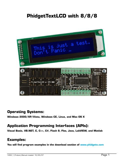
<strong>PhidgetTextLCD</strong> <strong>with</strong> 8/8/8<br />
Operating Systems:<br />
Windows 2000/XP/Vista, Windows CE, Linux, and Mac OS X<br />
Application Programming Interfaces (APIs):<br />
Visual Basic, VB.NET, C, C++, C#, Flash 9, Flex, Java, LabVIEW, and Matlab<br />
Examples:<br />
You will find program examples in the download section of www.phidgets.com<br />
1202_1_Product_Manual created: 10/23/07 Page 1
What Can the <strong>PhidgetTextLCD</strong> do?<br />
The <strong>PhidgetTextLCD</strong> allows you to display messages on a 2-line by 20-character<br />
LCD screen. The on-board InterfaceKit 8/8/8 allows you to connect devices to<br />
any of 8 analog inputs, 8 digital inputs, or 8 digital outputs. The <strong>PhidgetTextLCD</strong><br />
provides a generic, convenient way to interface various devices <strong>with</strong> your PC.<br />
Analog inputs<br />
They are used to measure continuous quantities, such as temperature, humidity, position,<br />
pressure, etc. Phidgets offers a wide variety of sensors that can be plugged directly into the<br />
board using the cable included <strong>with</strong> the sensor. Here is a list of sensors currently available:<br />
IR Distance Sensor IR Reflective Sensor Vibration Sensor Light Sensor<br />
Force Sensor Humidity Sensor Temperature Sensor Magnetic Sensor<br />
Rotation Sensor Voltage Divider Touch Sensor Motion Sensor<br />
Mini Joy-Stick Pressure Sensor Voltage Sensor Current Sensor<br />
Slide Sensor<br />
1202_1_Product_Manual created: 10/23/07 Page 2
Non Phidgets Sensors<br />
In addition to Phidgets sensors, any sensor that returns a signal between 0 and 5 volts<br />
can be easily interfaced. Here is a list of interesting sensors that can be used <strong>with</strong> the<br />
PhidgetInterfaceKit 8/8/8. Note: these sensors are not “plug & play” like Phidgets sensors.<br />
Manufacturer Part Number Description<br />
MSI Sensors FC21/FC22 Load cells - measure up to 100lbs of force<br />
Humirel HTM2500VB Humidity sensors<br />
Measurement Specialties MSP-300 Pressure sensors - ranges up to 10,000 PSI<br />
Freescale Semiconductor MPXA/MPXH Gas Pressure Sensors<br />
Allegro ACS7 series Current Sensors - ranges up to 200 Amps<br />
Allegro A1300 series Linear Hall Effect Sensors - to detect magnetic<br />
fields<br />
Analog<br />
TMP35 TMP36 Temperature Sensor<br />
TMP37<br />
Panasonic AMN series Motion Sensors<br />
Note: Most of the above sensors can be bought at www.digikey.com.<br />
Digital Inputs<br />
Digital Inputs can be used to convey the state of push buttons, limit switches, relays (check<br />
out our Dual Relay Board), logic levels, etc...<br />
Digital Outputs<br />
Digital Outputs can be used to drive LEDs, solid state relays (have a look at our SSR board),<br />
transistors; in fact, anything that will accept a CMOS signal.<br />
Digital outputs can be used to control devices that accept a +5V control signal.<br />
With transistors and some electronics experience, other devices can be controlled, such as<br />
buzzers, lights, larger LEDs, relays.<br />
1202_1_Product_Manual created: 10/23/07 Page 3
Getting Started<br />
Installing the hardware<br />
The kit contains:<br />
• A <strong>PhidgetTextLCD</strong><br />
• A custom USB Cable<br />
You will also need:<br />
• A piece of wire to test the digital inputs<br />
• An LED to test the digital outputs<br />
• An analog sensor to test the analog inputs<br />
2<br />
4<br />
3<br />
1<br />
1. Connect the analog sensor to any of the analog input ports (labelled 0 to 7) using a<br />
Phidgets sensor cable.<br />
2. Connect one end of the wire to a digital input port and the other end to the ground<br />
connection terminal.<br />
3. Connect the LED to one of the digital outputs by inserting the longer lead of the LED<br />
(anode) into any of the digital outputs (labelled 0 to 7) and the shorter lead (cathode) to<br />
ground.<br />
4. Connect the <strong>PhidgetTextLCD</strong> board to the PC using the USB cable.<br />
1202_1_Product_Manual created: 10/23/07 Page 4
Download and Install the software<br />
Go to www.phidgets.com >> downloads<br />
Select your operating system (Windows, Linux, MAC OS)<br />
Select the language you want to use and download the appropriate examples and Libraries.<br />
Install the Libraries and decompress the Example file.<br />
Testing the <strong>PhidgetTextLCD</strong> using Windows<br />
• Note that some examples are not available for Linux, Mac OSX or Windows CE.<br />
• Make sure that you have installed the libraries and decompressed your example file.<br />
Run the program Manager-full to make sure that the <strong>PhidgetTextLCD</strong> is properly connected<br />
to your PC. Both the <strong>PhidgetTextLCD</strong> and the on-board PhidgetInterfaceKit 8/8/8 should be<br />
listed in the Phidget Manager.<br />
1202_1_Product_Manual created: 10/23/07 Page 5
Testing the TextLCD<br />
1<br />
7<br />
8<br />
2 3<br />
4<br />
5 6<br />
1. Run the program TextLCD-full and check that the box labelled Attached contains the<br />
word True.<br />
2.<br />
3.<br />
4.<br />
5.<br />
6.<br />
7.<br />
8.<br />
Click on the Backlight box. The LCD screen will light up.<br />
Click on the Cursor Blink box. A square blinking cursor will appear on the LCD screen.<br />
Click on the Cursor box. A “dash” cursor will appear on the LCD screen.<br />
Click on the Custom Character box. The message “Testing Custom Chars” will appear on<br />
the first line of the LCD screen, followed by some random pictograms on the second line.<br />
You can increase or decrease the LCD screen contrast by moving the Contrast slider.<br />
You can type in a 2 line message to be displayed on the LCD screen.<br />
Click on the Clear button to clear the Display Text boxes and the LCD screen.<br />
1202_1_Product_Manual created: 10/23/07 Page 6
Testing the InterfaceKit 8/8/8<br />
1<br />
3<br />
2<br />
4<br />
5<br />
1. Run the program InterfaceKit-full and check that the box labelled Attached contains the<br />
word True.<br />
2.<br />
3.<br />
4.<br />
5.<br />
Test the digital output by clicking on the Digital Out box to turn on the LED. Clicking again<br />
will turn the LED off.<br />
Test the digital input by disconnecting the wire end connected to the digital input<br />
connector. The tick mark in the Digital In box will go away.<br />
Test the analog input sensor by observing the sensor value as you activate the Phidget<br />
sensor.<br />
You can adjust the input sensitivity by moving the Sensitivity slider.<br />
1202_1_Product_Manual created: 10/23/07 Page 7
Programming a Phidget<br />
Where to get information<br />
• Go to www.phidgets.com >> downloads<br />
• Select the Operating System and the language you want to use.<br />
• Download the appropriate API manual and read the section under the TextLCD heading.<br />
• Have a look at the source code of the TextLCD - full program.<br />
• Have a look at the C# example below.<br />
• Modify an existing program or write your own program from scratch.<br />
Simple example written in C#<br />
/* - TextLCD simple -<br />
* This simple example set up a TextLCD, waits for one to be attached, and then prompts the user to<br />
* enter two lines of text to be displayed on the TextLCD<br />
*<br />
* Please note that this example was designed to work <strong>with</strong> only one Phidget TextLCD connected.<br />
* For an example using multiple Phidget TextLCDs, please see a “multiple” example in the TextLCD<br />
* Examples folder.<br />
*<br />
* Copyright 2007 Phidgets Inc.<br />
* This work is licensed under the Creative Commons Attribution 2.5 Canada License.<br />
* To view a copy of this license, visit http://creativecommons.org/licenses/by/2.5/ca/<br />
*/<br />
using System;<br />
using System.Collections.Generic;<br />
using System.Text;<br />
using Phidgets; //Needed for the TextLCD class and PhidgetException Class<br />
using Phidgets.Events; //Needed for the event handling classes<br />
namespace TextLCD_simple<br />
{<br />
class Program<br />
{<br />
static void Main(string[] args)<br />
{<br />
try<br />
{<br />
//set up our Phidget TextLCD and hook the event handlers<br />
TextLCD tLCD = new TextLCD();<br />
tLCD.Attach += new AttachEventHandler(tLCD_Attach);<br />
tLCD.Detach += new DetachEventHandler(tLCD_Detach);<br />
tLCD.Error += new ErrorEventHandler(tLCD_Error);<br />
1202_1_Product_Manual created: 10/23/07 Page 8
tLCD.open();<br />
//We have to wait to make sure that a TextLCD is plugged in before trying to<br />
//communicate <strong>with</strong> it<br />
if(!tLCD.Attached)<br />
{<br />
Console.WriteLine(“Waiting for TextLCD to be attached....”);<br />
tLCD.waitForAttachment();<br />
}<br />
//prompt for the first line of input, Phidget TextLCD have two display lines<br />
Console.WriteLine(“Enter text to display on line 1:”);<br />
string line1 = Console.ReadLine();<br />
//make sure a TextLCd is still attached before trying to communicate <strong>with</strong> it...this is<br />
//for if the TextLCd has been detached while waiting for user input<br />
if (tLCD.Attached)<br />
{<br />
if (line1.Length > tLCD.rows[0].MaximumLength)<br />
{<br />
while (line1.Length > tLCD.rows[0].MaximumLength)<br />
{<br />
Console.WriteLine(“Entered text is too long, try again...”);<br />
line1 = Console.ReadLine();<br />
}<br />
}<br />
else<br />
{<br />
if (tLCD.Attached)<br />
{<br />
tLCD.rows[0].DisplayString = line1;<br />
}<br />
}<br />
}<br />
//prompt for the second line of input<br />
Console.WriteLine(“Enter text to display on line 2:”);<br />
string line2 = Console.ReadLine();<br />
//make sure a TextLCd is still attached before trying to communicate <strong>with</strong> it...this is<br />
//for if the TextLCd has been detached while waiting for user input<br />
1202_1_Product_Manual created: 10/23/07 Page 9
if (tLCD.Attached)<br />
{<br />
if (line2.Length > tLCD.rows[1].MaximumLength)<br />
{<br />
while (line2.Length > tLCD.rows[1].MaximumLength)<br />
{<br />
Console.WriteLine(“Entered text is too long, try again...”);<br />
line2 = Console.ReadLine();<br />
}<br />
}<br />
else<br />
{<br />
if (tLCD.Attached)<br />
{<br />
tLCD.rows[1].DisplayString = line2;<br />
}<br />
}<br />
}<br />
//Close the phidget<br />
tLCD.close();<br />
Console.WriteLine(“ok”);<br />
}<br />
catch (PhidgetException ex)<br />
{<br />
//output any exception data to the console<br />
Console.WriteLine(ex.ToString());<br />
}<br />
}<br />
//attach event handler, we’ll output the name and serial of the TextLCD that was attached<br />
static void tLCD_Attach(object sender, AttachEventArgs e)<br />
{<br />
TextLCD attached = (TextLCD)sender;<br />
string name = attached.Name;<br />
string serialNo = attached.SerialNumber.ToString();<br />
Console.WriteLine(“TextLCD name:{0} serial No.: {1} Attached!”, name, serialNo);<br />
}<br />
//Detach event handler, we’ll output the name and serial of the phidget that is detached<br />
static void tLCD_Detach(object sender, DetachEventArgs e)<br />
{<br />
TextLCD detached = (TextLCD)sender;<br />
1202_1_Product_Manual created: 10/23/07 Page 10
string name = detached.Name;<br />
string serialNo = detached.SerialNumber.ToString();<br />
Console.WriteLine(“TextLCD name:{0} serial No.: {1} Detached!”, name, serialNo);<br />
}<br />
//TextLCD error event handler, we’ll just output any error data to the console<br />
static void tLCD_Error(object sender, ErrorEventArgs e)<br />
{<br />
Console.WriteLine(“LCD Error: e.Description”);<br />
}<br />
}<br />
}<br />
1202_1_Product_Manual created: 10/23/07 Page 11
Technical Section<br />
LCDs<br />
Liquid Crystal Displays are display devices used to convey information through arrangements of<br />
pixels. Graphic and Text LCDs are the most common types available for electronic products.<br />
The <strong>PhidgetTextLCD</strong>’s display is configured as a 2X20 LCD (2 lines high, 20 characters per<br />
line) <strong>with</strong> each character having an arrangement of 40 pixels (8 pixels high by 5 pixels wide).<br />
2X20 LCD Character Arrangement<br />
Special Characters in the ASCII Standard Set<br />
The <strong>PhidgetTextLCD</strong> displays full text strings set in software. Since text characters are defined<br />
from the ASCII standard library, other ASCII standard set characters and glyphs can also be<br />
sent to the text LCD. This can be done easily by using unicode characters <strong>with</strong>in your text<br />
string. In C#, this may look something like this:<br />
tLCD.rows[0].DisplayString = “Apple starts <strong>with</strong> \u0041”;<br />
In this example, the string \u indicates that a unicode character follows, and the unicode character<br />
0041 (which references the hexadecimal character code 0x41) represents the capital<br />
letter A. After the LCD converts the unicode character, the above example would cause the<br />
LCD screen to read Apple starts <strong>with</strong> A. A chart of all ASCII standard set character codes is<br />
available in the Appendix at the end of this manual.<br />
Custom Characters<br />
Custom characters can also be generated for the <strong>PhidgetTextLCD</strong>. A custom character can<br />
be any arrangement of pixels <strong>with</strong>in the space alotted for a single character. Single characters<br />
are made up of pixels arranged in a grid 5 pixels wide by 8 pixels high. Once generated,<br />
custom characters can be stored in any one of eight volatile memory locations on the<br />
<strong>PhidgetTextLCD</strong>, and can be recalled <strong>with</strong> a simple API command from software.<br />
When custom characters are designed, a formula is used to change the pixel design into a<br />
pair of numerical values. The first value relates to the design of the top 4 rows of the character,<br />
and the second value relates to the design of the bottom 4 rows of the character. Unlike<br />
the unicode characters used in the Special Characters section above, the calculated number<br />
is not in hexadecimal format but is an integer value up to six characters in length.<br />
1202_1_Product_Manual created: 10/23/07 Page 12
Custom Characters (cont’d)<br />
The calculation for custom characters can be done by hand, or can be completed for you by<br />
using the form available at www.phidgets.com/documentation/customchar.html. Done by<br />
hand, each integer value represents the sum of two<br />
to the power of each individual on-pixel’s location <strong>with</strong>in<br />
that integer-value’s half of the character. Pixels not 4 3 2 1 0<br />
turned on are valued at zero. For example, a custom<br />
character happy-face <strong>with</strong> pixels 6, 8, 11 and 13 in 9 8 7 6 5<br />
the upper half turned on, pixels 1, 3, 6, 8, 11, 12<br />
and 13 in the lower half turned on, and all other pixels 14 13 12 11 10<br />
turned off, would result in the following integer values:<br />
VAL UPPER<br />
= 2 6 + 2 8 + 2 11 + 2 13 = 10560<br />
VAL LOWER<br />
= 2 1 + 2 3 + 2 6 + 2 8 + 2 11 + 2 12 + 2 13 = 14666<br />
These two values are then stored in one of eight memory<br />
locations (CG-RAM 0 to 7) on the <strong>PhidgetTextLCD</strong><br />
by using the Set Custom Character method in software.<br />
In C#, this may look something like this:<br />
tLCD.customCharacters[0].<br />
setCustomCharacter(10560, 14666);<br />
Once stored, characters can be recalled into a text<br />
string by either using the unicode value for the location<br />
5X8 LCD Character Pixel Arrangement<br />
as referenced in the ASCII chart (Appendix A) or by using<br />
the String Code method from the API. Examples in C# of both methods are shown below:<br />
19<br />
18<br />
17<br />
16<br />
1202_1_Product_Manual created: 10/23/07 Page 13<br />
4<br />
9<br />
14<br />
19<br />
3<br />
8<br />
13<br />
18<br />
Using the Analog Inputs<br />
2<br />
7<br />
12<br />
17<br />
tLCD.rows[0].DisplayString = “I am happy \u0008”;<br />
tLCD.rows[0].DisplayString = “I am happy ” +<br />
tLCD.customCharacters[0].StringCode;<br />
1<br />
6<br />
11<br />
16<br />
15<br />
0<br />
5<br />
10<br />
15<br />
The Analog Input can measure a voltage<br />
between 0V and 5V. The analog measurement is<br />
represented in the software as a value between 0<br />
and 1000, so a sensor value of 1 unit represents<br />
a voltage of approximately 5 millivolts.<br />
Each analog input uses a 3-pin, 0.100 inch pitch<br />
locking connector. Pictured here is a plug <strong>with</strong> the<br />
connections labeled. If this is wired backwards,<br />
damage to your sensor may result. The Interface<br />
Kit provides + 5VDC, ground, and an analog input<br />
<strong>with</strong> a range of 0 to 5V.
Ratiometric Sensors<br />
If you are using a sensor whose output changes linearly <strong>with</strong> variations in the sensor’s supply<br />
voltage level, it is said to be ratiometric. Most of the sensors sold by Phidgets are ratiometric<br />
(this is specified in the manual for each sensor).<br />
If the analog sensors you are using are ratiometric, enable the ratiometric property in software.<br />
This causes the reference to the internal Analog to Digital Converter to be set to the<br />
power supply voltage level. If ratiometric is not<br />
enabled, the ADC reference is set to a 5.0V<br />
User<br />
Phidget<br />
0.5% stable voltage reference.<br />
V+<br />
Using the Digital Inputs<br />
To wire a switch to a digital input, connect<br />
the switch between an input, labeled 0 to 7,<br />
and a provided ground, labeled G. The default<br />
state of the Digital Input in software is False<br />
(the switch state is open and the input pin is<br />
pulled to 5V by an internal resistor). When<br />
the switch is closed, the input pin is pulled to<br />
ground and the Digital Input is set to True.<br />
INPUT<br />
GROUND<br />
15KΩ<br />
15KΩ<br />
Digital Input Diagram<br />
Using the Digital Outputs<br />
Connecting an LED or other circuit to a digital<br />
output is simple. In the case of an LED, wire<br />
the anode to a digital output labeled 0 to 7<br />
on the Interface Kit, and the cathode to a<br />
supplied ground, labeled G.<br />
V+<br />
Phidget<br />
OUTPUT<br />
User<br />
The 300 ohm resistance is internal to the<br />
PhidgetInterfaceKit 8/8/8, and limits the<br />
current that can flow through the output.<br />
This is intended to protect the device from<br />
being damaged if there is a short to ground<br />
or if an LED is used. The output is intended<br />
to drive TTL or CMOS inputs; it is not<br />
designed to provide power to an external<br />
circuit.<br />
300Ω<br />
GROUND<br />
Digital Output Diagram<br />
The digital outputs can be used to switch larger electrical currents and voltages using devices<br />
such as power transistors, or logic level MOSFETs. You can also use the 3051 or 3052 to<br />
control a larger load.<br />
1202_1_Product_Manual created: 10/23/07 Page 14
Device Specifications<br />
Analog Input Impedance<br />
Digital Output Series Resistance<br />
Digital Input Pull-Up Resistance<br />
Digital Input Threshold Voltage (High-Low Transition)<br />
Digital Input Threshold Voltage (Low-High Transition)<br />
900K ohms<br />
300 ohms<br />
15K ohms<br />
1VDC<br />
4VDC<br />
Analog Input Update Rate<br />
Digital I/O Update Rate<br />
~65 samples / second<br />
~125 samples / second<br />
Digital I/O Recommended Wire Size<br />
Digital I/O Wire Stripping<br />
16 - 26 AWG<br />
5 - 6mm strip<br />
USB-Power Current Specification<br />
Quiescent Current Consumption<br />
Available External Current (source)<br />
Max 500mA<br />
50mA<br />
450mA<br />
Cable and Connector Components for Analog Inputs<br />
Manufacturer Part Number Description<br />
Molex 50-57-9403 3 Position Cable Connector<br />
Molex 16-02-0102 Wire Crimp Insert for Cable Connector<br />
Molex 70543-0002 3 Position Vertical PCB Connector<br />
Molex 70553-0002 3 Position Right-Angle PCB Connector (Gold)<br />
Molex 70553-0037 3 Position Right-Angle PCB Connector (Tin)<br />
Molex 15-91-2035 3 Position Right-Angle PCB Connector - Surface Mount<br />
Note: Most of the above components can be purchased at www.digikey.com<br />
Product History<br />
Date Product Revision Comment<br />
July 2005 DeviceVersion 120 Product Release<br />
Mechanical Drawing<br />
1:1 scale<br />
1202_1_Product_Manual created: 10/23/07 Page 15
Appendix A - ASCII Standard Character Set <strong>with</strong> Katakana Extension<br />
1202_1_Product_Manual created: 10/23/07 Page 16