Evacuated Tube Solar Collectors - Heatweb
Evacuated Tube Solar Collectors - Heatweb
Evacuated Tube Solar Collectors - Heatweb

Create successful ePaper yourself
Turn your PDF publications into a flip-book with our unique Google optimized e-Paper software.
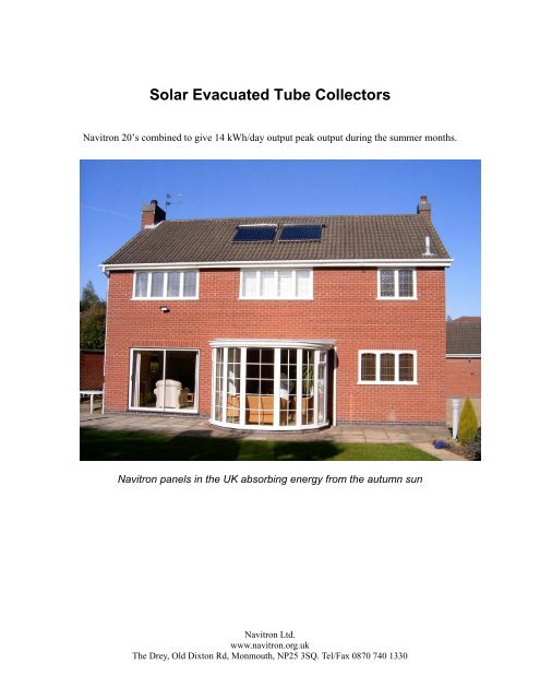
<strong>Solar</strong> <strong>Evacuated</strong> <strong>Tube</strong> <strong>Collectors</strong><br />
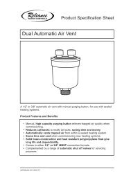
Navitron 20’s combined to give 14 kWh/day output peak output during the summer months.<br />
Navitron panels in the UK absorbing energy from the autumn sun<br />
Navitron Ltd.<br />
www.navitron.org.uk<br />
The Drey, Old Dixton Rd, Monmouth, NP25 3SQ. Tel/Fax 0870 740 1330
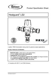
Freestanding collector designed for use with flat roof applications.<br />
Welcome to the Navitron <strong>Evacuated</strong> <strong>Tube</strong> <strong>Solar</strong> Collector! Whether you<br />
have just purchased your collector or are researching before you buy you<br />
have taken an important step to reducing pollution and carbon dioxide<br />
emission, whilst enjoying piping hot water heated by nature. This ‘solar<br />
collector’ has been manufactured to the very highest standards, and will<br />
provide you with many years of service, with the minimum of maintenance<br />
required. This brochure explains how your collector is intended to work,<br />
and provides information to allow you to complete a solar water heating<br />
installation. If, after reading this document, you have further questions,<br />
please contact your distributor, who will be happy to help you.<br />
Monthly Irradiation Figures:<br />
(<strong>Solar</strong> energy reaching each 1m 2 of the earth’s surface at UK latitudes)<br />
Jan Feb Mar Apr May Jun Jul Aug Sep Oct Nov Dec<br />
MJ/m 2<br />
2.3 4.2 7.0 11.6 15.0 18.0 16.0 13.0 10.0 6.0 2.8 1.7<br />
day<br />
kWh/day 0.64 1.17 1.94 3.22 4.17 5.00 4.44 3.61 2.78 1.67 0.78 0.47<br />
Navitron Ltd.<br />
www.navitron.org.uk<br />
The Drey, Old Dixton Rd, Monmouth, NP25 3SQ. Tel/Fax 0870 740 1330
Design:<br />
Our collectors are suitable for applications where aesthetics as well as efficiency<br />
are important. These collectors allow for easy installation and they are suitable<br />
for single unit installations or modular large-scale<br />
installations for heating or air conditioning<br />
projects. The main features are:<br />
• Long service life<br />
• Elegant aesthetically pleasing design<br />
• Easy integration into buildings<br />
• Improved power conversion at low solar<br />
irradiation levels<br />
Collector Dimensions<br />
The collector consists of the array of tubes, a heavily insulated manifold header,<br />
stainless steel support frame and standard mounting frame package. Each tube<br />
is 47mm x 1500mm and the overall dimensions of the panel are<br />
1760x1500x180mm. A 30 tube unit is also available for larger households.<br />
Navitron Ltd.<br />
www.navitron.org.uk<br />
The Drey, Old Dixton Rd, Monmouth, NP25 3SQ. Tel/Fax 0870 740 1330
Vacuum <strong>Tube</strong>s<br />
Unlike cheaper panels, this system does not heat the water directly within the<br />
vacuum tubes. Instead, a sealed copper ‘heat pipe’ transfers the heat via<br />
convection of its internal heat transfer fluid to a ‘hot bulb’ that indirectly heats a<br />
copper manifold within the header. The heat pipes are inserted into curved<br />
absorbers forming an assembly which in inserted into the glass tubes. The tubes<br />
are made of borosilicate glass, which is strong and has a high transmittance for<br />
solar irradiation. In order to reduce the convection heat lost, the glass tubes are<br />
evacuated to vacuum pressure or less than 10 -3 Pa. Stable vacuum seals are<br />
ensured by using a patented technique employing high heat and pressure. In<br />
order to keep the stability of the vacuum for a long time, a barium “getter” is used<br />
(the silver coating at the tip of the tube). This rare metal coating absorbs any<br />
gases that might eventually enter the tube, increasing the lifespan of the vacuum<br />
seal. Through evacuating air out of the glass tube the absorber material and<br />
selective coating are protected from corrosion and other environmental<br />
influences. This ensures a lifetime of at least 15 years without loss of efficiency.<br />
The getter also acts as an indicator and will turn white instantly should the tube<br />
be broken.<br />
Header Pipe<br />
The manifold has been designed around the use of a small diameter header pipe<br />
(28mm ID). This allows for a small manifold casing while still maintaining at least<br />
50mm of insulation. The water volume capacity of the header pipe is less than<br />
1.5 litres for the 30 tube collector, thus allowing fast heating during even overcast<br />
conditions. This is important for areas with lower solar irradiation or overcast<br />
conditions, as the heat from the manifold can be quickly harnessed, then held in<br />
the storage tank.<br />
The header pipe is brazed with Copper-Phosphorus brazing material (BcuP6),<br />
giving excellent joint penetration and smooth brazing. This result is a join that is<br />
not only strong, but also very neat. As the brazing material is primarily copper<br />
(94%), rapid heating and cooling of the header pipe does not compromise the<br />
weld integrity.<br />
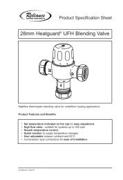
4 tube header pipe.<br />
Navitron Ltd.<br />
www.navitron.org.uk<br />
The Drey, Old Dixton Rd, Monmouth, NP25 3SQ. Tel/Fax 0870 740 1330
Close up of brazed header joint<br />
(CuP6 brazing rod)<br />
After brazing, every header pipe is pressure tested to ensure weld integrity. The<br />
inlet and outlet are formed in standard 22mm copper to enable the use of<br />
conventional compression fittings for the manifold plumbing. The copper manifold<br />
is heavily insulated using compressed rock wool. This reduces heat loss to a<br />
minimum at night, and during cold weather. In conjunction with our freezeprotection<br />
controller, there should be no requirement for antifreeze. The 50mm<br />
thick insulation is been used to protect against heat loss.<br />
The connection between the heat pipe and manifold is critically important to<br />
ensure optimal heat transfer. The manifold header pipe is mounted within the<br />
manifold casing and is made of 28mm diameter, 1 mm thick copper pipe rated for<br />
a maximum pressure of 10 kg/cm 2 , the standard operational maximum being<br />
6kg/cm 2 . The ‘hot bulb’ section of the heat pipe fits tightly in the heat pipe port in<br />
the manifold. Silicone heat-transfer compound (supplied with each kit) ensures a<br />
good transfer between heat pipe and the header pipe in the manifold. Heat<br />
transfer is by conduction allowing the manifold to remain fully sealed ensuring<br />
water can never leak at the connection.<br />
• Sealed manifolds make collector modules particularly suitable for areas<br />
with hard water (limescale)<br />
• Sealed manifolds allow the system to operate with high pressures of up to<br />
10 bar, especially useful in large heating or air conditioning projects.<br />
• Sealed manifolds eliminate leakages between manifold and vacuum tube.<br />
• Sealed manifolds make it easy to replace collector tubes at any time<br />
without interrupting the operation of system.<br />
Navitron Ltd.<br />
www.navitron.org.uk<br />
The Drey, Old Dixton Rd, Monmouth, NP25 3SQ. Tel/Fax 0870 740 1330
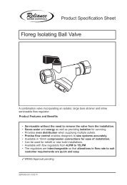
Rock Wool Insulation<br />
The choice of rock wool insulation is important for a number of reasons:<br />
• Rock wool can handle high temperatures, in fact it is non-flammable<br />
• Provides excellent insulation performance (often used in cavity insulation)<br />
• Is environmentally friendly as it is a natural, recyclable material<br />
Many companies are still using polyurethane, which provides excellent insulation<br />
performance, but is far from environmentally friendly. Focus collectors are as<br />
much as possible, a “Green” product.<br />
As you can see from the above picture, the rock wool is compressed into blocks.<br />
Each block is 73cm long, so 4 are used for a 20 tube collector, 6 in a 30 tube<br />
collector. The mold shape fits tightly around the header pipe and tube port shape<br />
to ensure maximum insulation performance.<br />
Frame<br />
Each collector is supplied with a stainless steel adjustable width frame. The<br />
frame is supplied plain, to match the manifold.<br />
Navitron Ltd.<br />
www.navitron.org.uk<br />
The Drey, Old Dixton Rd, Monmouth, NP25 3SQ. Tel/Fax 0870 740 1330
Uprights: Run the full height of the collector and are used for attachment to the<br />
mounting surface (roof, wall). Slots are punched out along the length for the<br />
attachment of mounting straps (stainless steel 'builders strap' is ideal ). Additional<br />
brackets/holes may be made according to your specific mounting requirements.<br />
The width between uprights is adjustable to suit individual installation<br />
requirements.<br />
Lower <strong>Tube</strong> Track: Used for the support and attachment of the evacuated<br />
tubes. The cups for the support of each tube are punched out of the stainless<br />
steel track with holes provided for the screw clamp to pass through.<br />
Screw Clamps: Because each heat pipes needs to maintain firm contact with<br />
the header pipe (for optimal heat transfer) it is important that every evacuated<br />
tube is held securely in place along the lower tube track. For this reason instead<br />
of plastic or rubber straps, stainless steel screw clamps are used. These clamps<br />
provide a convenient and fast attachment method that ensures secure tube<br />
attachment for the life of the collector. Installation or removal of a tube is quick<br />
and straightforwards, only a screwdriver is required to loosen the clamp<br />
Navitron Ltd.<br />
www.navitron.org.uk<br />
The Drey, Old Dixton Rd, Monmouth, NP25 3SQ. Tel/Fax 0870 740 1330
Manifold Straps: The manifold is secured to the uprights by means of aluminium<br />
or stainless steel straps (2 for 20 tube, 3 for 30 tube collector). The uprights are<br />
already fitted with nuts, so<br />
attachment with screws is a<br />
trouble free process. As the<br />
width between uprights is<br />
adjustable, the upright and<br />
straps location may be altered.<br />
Please note that the location of<br />
the upright and manifold strap<br />
(for various width adjustments)<br />
will always line up with the<br />
space between two tube ports<br />
(or outside the first and last<br />
tube). Both left and right<br />
uprights have 4 to 5 possible<br />
locations providing plenty of flexibility in the selection of frame width.<br />
The key features are as follows:<br />
• High performance, reliable, glass evacuated tubes<br />
• Heat pipe uses non-toxic, in-organic heat transfer compound<br />
• Low heat pipe start up temp (
Model Type<br />
Navitron SFB20<br />
Construction<br />
Vacuum <strong>Tube</strong> Collector<br />
No. of Collector Pipes 20<br />
<strong>Tube</strong> Diameter (OD)<br />
47mm<br />
Panel area 2.25m 2<br />
Absorber Surface 2.20 m 2<br />
LxWxH (mm)<br />
1760x1500x130<br />
Weight<br />
55kg<br />
Fluid Content<br />
1.5 l<br />
Pressure Drop@100 l hr -1<br />
10mBar<br />
Angle of Inclination<br />
15-90degrees<br />
Max. Temp (°C) 190°C<br />
Stagnation Temp (°C) 247°C<br />
Heat exchanger material<br />
Copper<br />
Permissible Operating Pressure 6bar<br />
Test Pressure<br />
10bar<br />
Manifold Connection Diameter 22mm<br />
No. of Vacuum <strong>Tube</strong> Port Diameter 20<br />
Component material specification Stainless steel / Aluminium header with<br />
rockwool insulation<br />
Interconnection Facility for multiple yes<br />
units<br />
Connection Diameter<br />
2 x 22mm<br />
Navitron Ltd.<br />
www.navitron.org.uk<br />
The Drey, Old Dixton Rd, Monmouth, NP25 3SQ. Tel/Fax 0870 740 1330
Additional Product Information and Background<br />
Sealed Glass <strong>Evacuated</strong> <strong>Tube</strong>s<br />
<strong>Evacuated</strong> tubes are the key component of the solar collector.<br />
The following information will provide you with insight into the history,<br />
manufacturing process and general specifications of evacuated tubes.<br />
<strong>Evacuated</strong> <strong>Tube</strong> History<br />
The evacuated tube technology was initially developed by Qing Hua University in<br />
Beijing in the early eighties, with pilot manufacturing in 1985. By 1988<br />
annual manufacturing volume by Qing Hua had reached 30,000 tubes. By 1996<br />
with the aid of significant financial support from the Chinese government, Qing<br />
Hua reached an annual production capacity of 2 million tubes. Continued<br />
infrastructure development led to 2.5 million tubes being sold in 1997.<br />
The majority of the tubes were used to supply the local market, with a small<br />
percentage (100,000 in 1995) being supplied to Japan, Europe, South America<br />
and South-East Asia. The main barrier to large export sales was the technology<br />
of the solar system (tank/manifold). Although the tubes performed well, the<br />
quality of the storage tanks was average, and did not meet the requirements of<br />
the European market. The non-pressure thermosiphon systems did, however,<br />
meet the needs of the Chinese market, and therefore sales grew and grew.<br />
In 1998 Qing Hua held 70% of the Chinese solar water heating market. With the<br />
breakup of some of the key members of the Qing Hua <strong>Solar</strong> board members, the<br />
patent protection for the tube technology was no longer enforceable, and so<br />
other Chinese companies began producing the evacuated tubes. The equipment<br />
and machinery used to produce all tubes in China is therefore the same as that<br />
developed by Qing Hua. For this reason, if engineering standards are followed,<br />
and good quality raw materials use, all tubes manufactured in China should be<br />
the same, and provide the same performance. You will find that all Chinese<br />
companies provide tubes with the same specifications. Having said this though,<br />
there are many companies who use poor quality raw material and make short<br />
cuts on engineering requirements. Selection of a professional tube manufacturer<br />
is therefore very important.<br />
Navitron Ltd.<br />
www.navitron.org.uk<br />
The Drey, Old Dixton Rd, Monmouth, NP25 3SQ. Tel/Fax 0870 740 1330
Navitron Product Development<br />
Full scale production of the Navitron model solar collector began in early April of<br />
2002. Since then collectors have been sold to the UK, France, Germany, Italy,<br />
The Netherlands and Ireland.<br />
Communication with customers and solar experts in Germany, the UK, Italy and<br />
the US provided the basis for many of the Navitron design features. For this<br />
reason it is very well suited to the needs of these markets, particularly in relation<br />
to packing and freight, installation, aesthetics, performance and overall quality.<br />
During the development of this collector it became clear that the European and<br />
US market needed a solar collector that met the following criteria:<br />
• High performance evacuated tube heat pipe based design<br />
• “Plug and Play” heat pipe system for easy transport, installation and<br />
maintenance (changing broken tubes)<br />
• Use of non-toxic heat pipe transfer liquid (not acetone)<br />
• High quality long lasting components (corrosion resistant materials)<br />
• High quality stainless steel finish<br />
• Excellent insulation properties (>50mm thick rock wool)<br />
• Small manifold water volume to ensure fast heating time<br />
• Environmentally friendly through the use of non-polluting, recyclable<br />
materials<br />
• Accept mains pressure water supply (6kg/cm 2 / 85psi)<br />
• Corrosion resistant manifold header pipe (copper)<br />
• Suitable for open or closed flow operation<br />
• Accept a standard sized temperature sensor<br />
• Compact frame that could be packed with the manifold<br />
• Adjustable width frame to allow for varying installation surfaces<br />
• Quick and simple tube attachment system – permitting easy removal of<br />
any one tube<br />
• Compact manifold size<br />
• Cost competitive with high quality flat plate collectors<br />
Certification<br />
Please note that the Navitron collector is manufactured in accordance with<br />
ISO9002, and it is currently undergoing testing to BS EN 12975 It is from these<br />
tests that the absorption (93%) and emission (7%) efficiency values have been<br />
verified. The glass manufacturing plant, ensures that quality is controlled<br />
throughout every step of the process. They have obtained a wide range of quality<br />
management and quality control certificates including the internationally<br />
recognized ISO9002 management standard.<br />
Navitron Ltd.<br />
www.navitron.org.uk<br />
The Drey, Old Dixton Rd, Monmouth, NP25 3SQ. Tel/Fax 0870 740 1330
EVACUATED TUBE & HEAT PIPE CHARACTERISTICS<br />
The heat pipe and evacuated tube will not get hot after one minute of sitting in<br />
the sun – so don’t expect it too. The sealed glass tubes have a short start-up<br />
time as the inner glass tube, heat pipe fins and air within the tube must first be<br />
heated before the temperature will start to rise considerably. In good conditions it<br />
will take less than 5 minutes for the tip of the heat pipe to get too hot to hold<br />
(>50deg C). The advantage of the sealed glass evacuated tube is that is acts as<br />
a heat store, providing a stable supply of heat to the manifold even during<br />
intermittently overcast weather. The tube will continue to provide heat even after<br />
the sun has set.<br />
A good test to show the heat storage capacity of the tube is to let the tube heat<br />
up outside until the heat pipe tip is hot. Run the tip under cold water for 10<br />
seconds or so to cool it down (drain some of the heat). Stand the tube back up,<br />
and within seconds the tip will be red hot again. This can be repeated several<br />
times before the heat is “used up”.<br />
Another example of the heat storage is to let a tube heat up outside in the sun,<br />
and then bring it inside. You will find after half an hour the tip will still be hot, thus<br />
demonstrating the store of heat (energy) inside the tube.<br />
The sealed glass evacuated tube provides a stable supply of heat even during<br />
intermittent weather. There is minimal “peaking and troughing” of heat supply as<br />
the clouds intermittently block the sunlight. Heat supply can therefore continue<br />
even when there is no sunlight striking the collector, due to the store of heat<br />
within the evacuated tube.<br />
NB – DO NOT EXPOSE TUBES TO SUNLIGHT FOR EXTENDED PERIODS<br />
WITHOUT COOLING THE TIPS, OR DAMAGE MAY OCCUR. Install header<br />
first, and shade tubes from sunlight until the water flow and control is<br />
operational<br />
Heat Pipes<br />
In addition to the evacuated tubes the copper heat pipe is also vital to the<br />
performance of the collector. The heat pipe is an essential link in the heat<br />
transfer chain. If this link is poor quality then the efficiency of the whole system<br />
will be compromised, regardless of how good the evacuated tubes are.<br />
The key factors to consider when choosing a heat pipe are:<br />
• Operating Temperature Range<br />
• Heat transfer compound<br />
• Heat transfer performance<br />
• Operating life expectancy<br />
Navitron Ltd.<br />
www.navitron.org.uk<br />
The Drey, Old Dixton Rd, Monmouth, NP25 3SQ. Tel/Fax 0870 740 1330
Heat pipes in the Navitron collector are custom made using patented inorganic,<br />
nontoxic heat transfer compound.<br />
The Inorganic heat pipes have the following features:<br />
• Continuous operating life of more than 110,000 hours (5 year warranty)<br />
• Effective thermal conductance of 25,000 – 30,000 times that of silver.<br />
• Heat flux density of 27.2MW/m 2 .<br />
• Heat pipe internal surface is coated with 3 layers, which delay corrosion<br />
and oxidation and prevent the production of oxy hydrogen, thus improving<br />
the performance stability and operation life of the heat pipe.<br />
• The heat pipe transfers heat along the full length of the heat pipe in a sine<br />
wave pattern, with a thermal resistance of almost zero.<br />
• Heat transfer compound is non-toxic if ingested and nonirritant to either<br />
eyes or skin.<br />
• Vacuum level of 4x10 -6 Pa which reduces the boiling temp of the liquid to<br />
as low as 25-30deg C<br />
In addition to having a high<br />
quality heat pipe, the fins used<br />
within the evacuated tube are<br />
curved copper fins. We have<br />
found a performance increase of<br />
5% using this new fin design<br />
when compared to the flat fins<br />
previously used.<br />
Navitron Ltd.<br />
www.navitron.org.uk<br />
The Drey, Old Dixton Rd, Monmouth, NP25 3SQ. Tel/Fax 0870 740 1330
HEAT PIPE CHARACTERISTICS<br />
The heat pipes used by Navitron Ltd are different to some other heat pipes,<br />
which use acetone as the heat transfer compound. Acetone heat pipes will<br />
transfer heat with just the bottom 5 to 10cm placed in a cup of hot water (50deg<br />
C). Ours will not. This is not because the performance is poor, but rather<br />
because the nature of the heat transfer compound is quite different. Under the<br />
vacuum conditions that exist in the heat pipe, and at low heat pipe temperatures<br />
(45 deg C) can be poured along the<br />
bottom two-thirds of the heat pipe. This will ensure rapid melting of the ball and<br />
subsequent heat transfer to the tip. Within 60 seconds the tip can achieve a<br />
temperature, which is 90-95% of the temperature it is exposed to. The tip can<br />
never get hotter than the heat level it is exposed to (not 100% efficient).<br />
Although the heat pipe can transfer heat at temperatures of around 30-35 o C, the<br />
heat transfer to the tip will only reach 28-32 o C, which will not feel hot to the<br />
touch. So don’t try and use warm water for demonstration purposes. Use hot<br />
water.<br />
NB – DO NOT EXPOSE TUBES TO SUNLIGHT FOR EXTENDED PERIODS<br />
WITHOUT COOLING THE TIPS, OR DAMAGE MAY OCCUR. Install header<br />
first, and shade tubes from sunlight until the water flow and control is<br />
operational<br />
Navitron Ltd.<br />
www.navitron.org.uk<br />
The Drey, Old Dixton Rd, Monmouth, NP25 3SQ. Tel/Fax 0870 740 1330
Collector Frame<br />
Assembling The Navitron <strong>Solar</strong> Collector<br />
There are many different types of roofing materials, and solar collectors can be<br />
mounted at various angles, either on the surface of the roof or on a framework to<br />
achieve the optimum angle on shallow pitch roofs. The mounting frame provided<br />
consists of two side rails and a top and bottom support assembly. All frames are<br />
made of stainless steel and are designed to be quick and easy to install on all<br />
roof types. There are two ways to fix the frame to the roof – either drill directly<br />
through the tiles and use coach screws into the rafters (the most popular method<br />
among professional installers) – you can then seal the hole with silicone sealant.<br />
Alternatively, use builders strap available at any builders’ merchants. Simply slide<br />
these up underneath the tiles (fixing directly to the rafters underneath the tiles.<br />
1. Frame Assembly<br />
(1) Assemble Uprights<br />
Nb:The frame should be fully assembled prior to installation of vacuum tubes.<br />
Assemble the 2 uprights as shown below:<br />
Navitron Ltd.<br />
www.navitron.org.uk<br />
The Drey, Old Dixton Rd, Monmouth, NP25 3SQ. Tel/Fax 0870 740 1330
(2) Attach the manifold<br />
Attach the manifold to the uprghts, securing the manifold with the Manifold<br />
Fixing Loop, secured by the screws enclosed with the collector. (See<br />
below)<br />
(3) Fix the Lower <strong>Tube</strong> Track<br />
Attach the tube track to the protrusions of at the base of the uprights, fixing<br />
with long screws. (See picture below)<br />
Navitron Ltd.<br />
www.navitron.org.uk<br />
The Drey, Old Dixton Rd, Monmouth, NP25 3SQ. Tel/Fax 0870 740 1330
You have now finished the frame/manifold assembly. (The diagram below shows<br />
how the assembled item will look)<br />
Navitron Ltd.<br />
www.navitron.org.uk<br />
The Drey, Old Dixton Rd, Monmouth, NP25 3SQ. Tel/Fax 0870 740 1330
2. Install the vacuum tubes<br />
• Place the rubber cap on the end of the first evacuated tube.<br />
• Apply silicon grease to the top of the evacuated tube (the copper section),<br />
then insert into the manifold.<br />
• Secure the end of the vacuum tube to the frame bar with the ‘jubilee’<br />
screw clamp, clamping the protective rubber cap.<br />
• Repeat the installation with each of the remaining vacuum tubes as<br />
described above.<br />
• When installing vacuum tubes ensure they are always held securely either<br />
in the box or in the frame. Never put them down unsecured on a roof.<br />
• Ensure vacuum tubes are covered during installation. The tubes can be<br />
become dangerously hot during the day before water is flowing in the<br />
manifold header. Only remove the cover when the system has water<br />
running through it.<br />
Navitron Ltd.<br />
www.navitron.org.uk<br />
The Drey, Old Dixton Rd, Monmouth, NP25 3SQ. Tel/Fax 0870 740 1330
3. Install the sectional reflector<br />
Reflectors<br />
The efficiency of the panel is increased by fitting reflectors so that the sunlight<br />
falling between the tubes is not wasted. The reflector is supplied as a set of 19<br />
pressed stainless forms which are clamped between each tube using special<br />
plastic clips. The diagrams below demonstrate how the reflectors are assembled:<br />
• Put one section of reflector between two vacuum tubes.<br />
• Insert the Special fixings (Plastic clips) into the hole at one end of the<br />
reflector and rotate 90°. Now one end of the reflector is fixed between two<br />
vacuum tubes.<br />
• Similarly, secure the other end of the reflector.<br />
• Repeat for the remaining 18 sections of reflector as described above.<br />
The sketch below shows a cutaway view of reflector installation.<br />
Special fixing<br />
Vacuum tube<br />
Vacuum tube<br />
Sectional reflector<br />
Navitron Ltd.<br />
www.navitron.org.uk<br />
The Drey, Old Dixton Rd, Monmouth, NP25 3SQ. Tel/Fax 0870 740 1330
The Finished Picture of ‘Navitron’ SFB20<br />
Navitron Ltd.<br />
www.navitron.org.uk<br />
The Drey, Old Dixton Rd, Monmouth, NP25 3SQ. Tel/Fax 0870 740 1330
<strong>Solar</strong> Controller: Essential for efficient use of <strong>Solar</strong> Heating<br />
The solar controller is an essential part of the solar heating system, in all but<br />
gravity-fed systems (where the Navitron <strong>Solar</strong> Collector is situated lower than the<br />
hot water cylinder, and circulation is effected by thermo-syphoning). In all other<br />
systems, it will be necessary to use a controller to switch on the pump when the<br />
panel is hotter than the hot water storage cylinder. The controller may also be<br />
configured to circulate the water to heat the panel in the event that the solar<br />
collector becomes dangerously close to freezing. This will only happen in<br />
exceptionally cold weather, and will represent a negligible energy drain.<br />
Controllers should be fitted that allow the installer to adjust the temperature<br />
differential to suit different pipe runs with different heat-losses. More advanced<br />
controllers will display the temperature of the collector and of the hot water<br />
cylinder, or can control more than one pump or control valve, to allow multiple<br />
panels on different roof elevations. We recommend RESOL controllers, as they<br />
are the industry-leaders, and produce high quality, reliable equipment. The B1<br />
Controller is the simplest and cheapest unit, but is extremely effective. We<br />
recommend this for most installations.<br />
For more than 25 years the controller RESOL B1<br />
leads by its simple and robust concept. Due to its<br />
huge adjustment range and its adjustable<br />
temperature difference, this low-priced universal<br />
differential temperature controller is usually first<br />
choice for solar heating systems.<br />
• Low-priced differential temperature controller for solar-heating- and air<br />
conditioning systems<br />
• Adjustable temperature difference from 2 ... 16 K<br />
• Power supply 230 V (AC)<br />
• 2 temperature sensors are provided (included in full kit)<br />
Navitron Ltd.<br />
www.navitron.org.uk<br />
The Drey, Old Dixton Rd, Monmouth, NP25 3SQ. Tel/Fax 0870 740 1330
DeltaSol® B The controller RESOL DeltaSol® B is used for application in<br />
standard solar thermal systems as well as in heating and air conditioning<br />
systems and persuades by its clear operation concept. A newly developed, multifunctional<br />
display enables the user to simultaneously request two temperatures<br />
(e.g. collector and store temperature). No annoying switching-over, no guessing<br />
but easy pictograms give the user clear information on function and operating<br />
status of the controller and the system. The version PG 53.02 is equipped with 2<br />
standard relay outputs, the version PG 51.02 is equipped with 1 standard relay<br />
output as well as 3 sensor inputs for Pt1000-sensors, store temperature limitation<br />
and manual switch. The central element is the 3-key-field below the display. The<br />
newly developed combined LCdisplay<br />
enables an intuitive and reliable controller configuration as well as a<br />
comprehensive visualisation of the system status. Collector cooling and recooling<br />
function as well as security switch-off, but also a thermostat function can be<br />
easily realised. The controller DeltaSol B is also available as individual OEMversion,<br />
so that further system adaptions are possible.<br />
Navitron Ltd.<br />
www.navitron.org.uk<br />
The Drey, Old Dixton Rd, Monmouth, NP25 3SQ. Tel/Fax 0870 740 1330
Technical data<br />
Housing: plastic, PC-ABS and<br />
PMMA<br />
Protection type: IP 40 / DIN<br />
40050<br />
Size: 172 x 110 x 46 mm<br />
Installation: wall mounting, mounting<br />
into patch panels is possible<br />
Display: LCD, multi-functional<br />
combined display with 8 pictograms,<br />
two 2-digit text fields and<br />
two 4-digit 7-segment displays as<br />
well as one 2-coloured luminescent<br />
diode<br />
Operation: by three pushbuttons<br />
in the front of the housing<br />
Functions: standard solar controller<br />
with adjustable values: minimummaximum<br />
temperature limitation,<br />
switch-on and switch-offtemperature<br />
difference. Frost protection<br />
/ cooling function, security<br />
.<br />
Navitron Ltd.<br />
www.navitron.org.uk<br />
The Drey, Old Dixton Rd, Monmouth, NP25 3SQ. Tel/Fax 0870 740 1330
<strong>Solar</strong> Collector Installation<br />
The installation of a Navitron solar collector can be completed in many ways,<br />
depending on a number of factors, such as:<br />
• climate (freeze protection, overheating concerns)<br />
• storage tank type (mains pressure, thermal store, gravity fed)<br />
• flow configuration (open flow, closed flow)<br />
• Controller configuration (PV powered pump, Delta T controller)<br />
• Installation location (roof, ground, wall)<br />
• System size (domestic, large scale application)<br />
• System purpose (water heater, central heating, refrigeration)<br />
As a professional solar installer, Navitron expects that you will know how to<br />
correctly install the collector to ensure efficient performance and system<br />
reliability. We can provide you some technical advice as required, but we may<br />
not be that familiar with the specifics of your region. When completing a system<br />
design the following points should be noted.<br />
1. The heat pipes do not have a temperature cut off like Thermomax, so<br />
pressure release valves and/or expansion chambers are required. Pressure<br />
should not exceed 85psi under normal use.<br />
2. The system is well insulated, and subzero temperatures will not damage the<br />
evacuated tubes or heat pipes, however the header and associated plumbing<br />
may be damaged by if the water freezes. Circulation of water through the<br />
collector when ambient temperatures are low is suggested as the best “antifreeze”<br />
method. Electrical supply to the pump must be guaranteed, to account<br />
for power blackouts (eg DC pump with battery backup).<br />
3. If using a closed system a glycol water mix can be used to provide adequate<br />
freeze protection.<br />
4. The manifold is not guarantee against limescale formation, so ensure that<br />
water is of suitable quality (closed loop system is suggested for areas with<br />
water that is acidic, hard or has high chloride levels)<br />
5. The following is a basic example of a configuration using a thermal store tank,<br />
collector and instant gas water heater. This system just supplies domestic hot<br />
water, but could easily be configured to also supply heat for infloor/ventilation<br />
heating. Thermal stores can be fitted with electric immersion heating as<br />
backup, and can accept direct heat input from gas, electric or wood heating<br />
sources.<br />
Navitron Ltd.<br />
www.navitron.org.uk<br />
The Drey, Old Dixton Rd, Monmouth, NP25 3SQ. Tel/Fax 0870 740 1330
Typical solar integrated heating system and domestic hot water for all year<br />
use.<br />
Navitron Ltd.<br />
www.navitron.org.uk<br />
The Drey, Old Dixton Rd, Monmouth, NP25 3SQ. Tel/Fax 0870 740 1330
<strong>Evacuated</strong> <strong>Tube</strong> <strong>Solar</strong> Domestic Hot water pre heat installation, gas backup<br />
Thermal Stores<br />
Thermal Stores offer the following key features:<br />
• Mains pressure hot water from an open-vented low-pressure tank (via<br />
brazed plate heat-exchanger)<br />
• Light, inexpensive and easy to install<br />
• Excellent corrosion resistance due to anaerobic tank environment<br />
• Provides passive thermal expansion and overheating protection via built in<br />
expansion chamber.<br />
• Can accept heat from secondary sources such as wood stove or gas<br />
burner.<br />
• Can supply hot water for in-floor heating, air-ventilation heating, spa<br />
heating.<br />
• Does not require complicated or expensive plumbing<br />
• Can use a glycol/water mix to provide enhanced freeze protection<br />
• Ideal for use with an “instant” (on demand) gas water heaters, thus<br />
ensuring virtually limitless hot water supply (Never run out of hot water<br />
again).<br />
Navitron Ltd.<br />
www.navitron.org.uk<br />
The Drey, Old Dixton Rd, Monmouth, NP25 3SQ. Tel/Fax 0870 740 1330
What is required for a DIY Installation?<br />
You can install a solar hot water heating system with a minimum of components,<br />
but there are many desirable components which improve efficiency and enhance<br />
the installation.<br />
ESSENTIAL:<br />
Navitron <strong>Solar</strong> manifold with 20 Vacuum <strong>Solar</strong> Heater <strong>Tube</strong>s<br />
Pipework<br />
Pipe insulation<br />
DESIRABLE<br />
Controller (essential if not using thermo-syphon principle)<br />
Twin coil <strong>Solar</strong> Hot Water Storage Cylinder<br />
Circulating Pump<br />
Automatic Air Vents<br />
OPTIONAL (depending on installation design):<br />
Expansion vessel and pressurized system kit<br />
Swimming pool kit (Direct Heat)<br />
Navitron <strong>Solar</strong> manifold with 20 Vacuum <strong>Solar</strong> Heater <strong>Tube</strong>s<br />
Stainless Steel Heat Exchanger (required if you add chlorine to your water – this<br />
is because the chlorine will corrode the copper inside the solar collector’s<br />
header)<br />
Electronic Controller<br />
Pump<br />
Navitron Ltd.<br />
www.navitron.org.uk<br />
The Drey, Old Dixton Rd, Monmouth, NP25 3SQ. Tel/Fax 0870 740 1330
Sample Schematics:<br />
1. ‘Hot <strong>Tube</strong>’ coil screwed into immersion heater flange<br />
Cheap and easy to install. Ideally requires immersion heater flange to be located<br />
in the lower part of the cylinder. Unfortunately, most modern hot water cylinders<br />
have top-mounted immersion heaters, which will not allow high efficiency when<br />
used to facilitate solar heating<br />
2. Direct heating(simplest method)<br />
Simplest method. Quite efficient, but in areas of hard water, eventually, the solar<br />
collector will get ‘furred up’ with limescale, which will reduce efficiency. Easy to<br />
retro-fit to an existing direct or indirect hot water cylinder.<br />
Navitron Ltd.<br />
www.navitron.org.uk<br />
The Drey, Old Dixton Rd, Monmouth, NP25 3SQ. Tel/Fax 0870 740 1330
3. Twin coil hot water tank<br />
This is the best method, but requires the added cost of a twin coil water cylinder.<br />
We can supply these at attractive prices, with the added advantage of a double<br />
layer of insulation(50mm), keeping heat losses to a minimum. Please contact for<br />
details<br />
Key to Diagrams:<br />
1. Navitron <strong>Solar</strong> manifold with 20 Vacuum <strong>Solar</strong> Heater <strong>Tube</strong>s<br />
2. Pressure Gauge<br />
3. Automatic Air Bleed<br />
4. Drain Cock<br />
5. Expansion Tank<br />
6. Gate Valve<br />
7. Single Check Valve<br />
8. Double Check Valve<br />
9. Filling Loop<br />
10. Circulating Pump<br />
11. Pressure Relief Valve<br />
12. Overflow<br />
Navitron Ltd.<br />
www.navitron.org.uk<br />
The Drey, Old Dixton Rd, Monmouth, NP25 3SQ. Tel/Fax 0870 740 1330