Object Capture with a Camera-Mobile Robot System - IEEE Xplore
Object Capture with a Camera-Mobile Robot System - IEEE Xplore
Object Capture with a Camera-Mobile Robot System - IEEE Xplore

You also want an ePaper? Increase the reach of your titles
YUMPU automatically turns print PDFs into web optimized ePapers that Google loves.
Making the <strong>Robot</strong> See<br />
Machine vision and image processing are very broad areas of<br />
research, and there is an ever-growing number of creative and<br />
useful methods for retrieving information from images. Many<br />
of these are quite complex, but what we desire here is a very<br />
simple way to make the mobile robot see its environment. Our<br />
mobile robot needs to know 1) where it is located, 2) what<br />
direction it is facing, 3) where the tennis ball target object(s) is,<br />
and 4) the location of any obstacles present.<br />
The RvCAD software will automatically import the video<br />
stream from the Webcam, and it provides a simple graphical<br />
interface where one can “wire” together blocks that perform<br />
different image processing functions. We first use a color<br />
threshold (a function built into RvCAD) to decide which pixels<br />
contain robot, tennis ball, background, or something else (an<br />
RS232 from<br />
Com Port<br />
USB or Firewire<br />
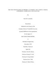
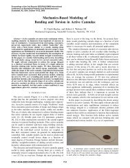
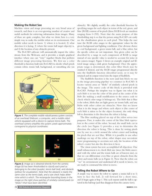
Figure 1. The complete mobile robot/camera system consists<br />
of an overhead Webcam, a computer, and a mobile robot<br />
vehicle equipped <strong>with</strong> a device to capture tennis balls. The<br />
overhead camera simplifies the system; pixels approximately<br />
correspond to physical coordinates.<br />
(a)<br />
Overhead<br />
<strong>Camera</strong><br />
Ball<br />
Trap<br />
(b)<br />
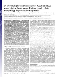
Figure 2. Image (a) is obtained directly from the camera.<br />
Image (b) has been thresholded to classify each pixel as<br />
belonging to the robot (purple), tennis ball (red), and obstacle<br />
(yellow) for visualization. Note that the obstacle is nearly the<br />
same color as the tennis balls, and a size check helps determine<br />
which is which. The rectangular bounding boxes in the<br />
image on the right show patches of similarly colored pixels (or<br />
“blobs”) that have been identified.<br />
obstacle). We slightly modify the color threshold function by<br />
specifying ranges for each object in terms of the red, green, and<br />
blue (RGB) content of its pixels (these RGB levels are numbers<br />
ranging from 0–255). Note that the main purpose of this<br />
thresholding step is so that the person using RvCAD can easily<br />
see the classification given to each pixel. This helps the user<br />
tune the RGB color ranges to the appropriate values for the<br />
given background and lighting conditions. One obvious choice<br />
is a red background, a green tennis ball, and a blue robot, but<br />
the specific colors are not important. Any given color can be<br />
described by a range in each component of RGB (a range<br />
instead of one specific value is needed to account for noise in<br />
the camera image). Figure 2 shows an example original and filtered<br />
image using a dark green background. Once the appropriate<br />
range is determined, this color filter block may be<br />
omitted if desired, and the RGB ranges programmed directly<br />
into the findblobs function (described next), or it may be<br />
retained and its output wired into the input of findblobs.<br />
The findblobs function is the next (and last) block we use<br />
in the image processing pipeline we construct in RvCAD. It<br />
locates various areas or “blobs” of similarly colored pixels in<br />
the image. The source code of this block is provided <strong>with</strong><br />
RvCAD. Perhaps the simplest way to figure out what is in<br />
each blob is to test the color of the pixel at the center of the<br />
blob (by making a small modification to the source code to<br />
check which color range it belongs to). The blob that is blue<br />
is the robot, blobs that are light green are tennis balls, and any<br />
blobs <strong>with</strong> other colors are obstacles. Now that we know<br />
what is in the image and where each object is (the center of<br />
each blob is taken to be the object location), the only thing<br />
left to determine is the direction the robot is facing.<br />
The blue marking placed on top of the robot serves two<br />
purposes. First, it makes the center of the blue blob equivalent<br />
to the center of the robot. Second, the small hole cut in<br />
the circle (see Figure 1) provides a way to determine the<br />
direction the robot is facing. This is done by testing pixels<br />
one by one in a circle around the robot center and looking<br />
for pixels that are not blue. While it is possible to use other<br />
markings on top of the robot, other shapes may necessitate<br />
more programming to ascertain not only the location of the<br />
robot’s center but also the direction it faces.<br />
The vision system has now accomplished all objectives. One<br />
small enhancement is to check blob size (since the blobs associated<br />
<strong>with</strong> the robot and the tennis balls are of known size), so<br />
that we can differentiate even blue or green obstacles from the<br />
robot and tennis balls (as in Figure 2). Now that the robot can<br />
“see” its environment and understand all it needs to know, we<br />
are ready to command the robot to move.<br />
Telling the <strong>Robot</strong> Where to Go<br />
A simple way to move the robot to capture a tennis ball is to 1)<br />
turn to face the ball, 2) roll forward for a short time,<br />
and 3) begin again at Step 1. This cycle repeats until the ball is captured<br />
in the ball trap (and thus disappears from the camera view).<br />
86<br />
<strong>IEEE</strong> <strong>Robot</strong>ics & Automation Magazine MARCH 2006