Online Body Tracking by a PTZ Camera in IP Surveillance System
Online Body Tracking by a PTZ Camera in IP Surveillance System
Online Body Tracking by a PTZ Camera in IP Surveillance System

You also want an ePaper? Increase the reach of your titles
YUMPU automatically turns print PDFs into web optimized ePapers that Google loves.
<strong>Onl<strong>in</strong>e</strong> <strong>Body</strong> <strong>Track<strong>in</strong>g</strong> <strong>by</strong> a <strong>PTZ</strong> <strong>Camera</strong> <strong>in</strong> <strong>IP</strong><br />
<strong>Surveillance</strong> <strong>System</strong><br />
Parisa Darvish Zadeh Varcheie, Guillaume-Alexandre Bilodeau<br />
Department of Computer Eng<strong>in</strong>eer<strong>in</strong>g and Software Eng<strong>in</strong>eer<strong>in</strong>g, École Polytechnique de Montréal<br />
P.O. Box 6079, Station Centre-ville Montréal, (Québec), Canada, H3C 3A7<br />
{parisa.darvish-zadeh-varcheie, guillaume-alexandre.bilodeau}@polymtl.ca<br />
Abstract—In this paper, an onl<strong>in</strong>e human body track<strong>in</strong>g<br />
method <strong>by</strong> an <strong>IP</strong> <strong>PTZ</strong> camera based on fuzzy-feature scor<strong>in</strong>ge is<br />
proposed. Because the surveillance system uses a built-<strong>in</strong> web<br />
server, the camera control entails camera response time and<br />
network delays. Thus, the frame rate is irregular and <strong>in</strong> general<br />
low (3-7 fps). Our method has been designed specifically to<br />
perform <strong>in</strong> such conditions. At every frame, candidate targets<br />
are detected <strong>by</strong> extract<strong>in</strong>g mov<strong>in</strong>g target us<strong>in</strong>g optical flow,<br />
a sampl<strong>in</strong>g, and appearance. The target is determ<strong>in</strong>ed among<br />
samples us<strong>in</strong>g a fuzzy classifier. Results show that our system<br />
has a good target detection precision (> 88%), and the target is<br />
almost always localized with<strong>in</strong> 1/4th of the image diagonal from<br />
the image center.<br />
I. INTRODUCTION<br />
One problem <strong>in</strong> video surveillance is how to identify and<br />
recognize events. Mov<strong>in</strong>g object detection and track<strong>in</strong>g is<br />
one of the key technologies for <strong>in</strong>telligent video monitor<strong>in</strong>g<br />
systems. Furthermore, people detection and track<strong>in</strong>g are important<br />
capabilities for applications that require natural humanmach<strong>in</strong>e<br />
<strong>in</strong>teractions. We propose to track objects us<strong>in</strong>g an<br />
<strong>IP</strong> <strong>PTZ</strong> camera (a network-based camera that pans, tilts and<br />
zooms). An <strong>IP</strong> <strong>PTZ</strong> camera responds to command via its<br />
<strong>in</strong>tegrated web server after some delays. <strong>Track<strong>in</strong>g</strong> with such<br />
camera implies: 1) irregular response time to control command,<br />
2) low irregular frame rate because of network delays<br />
(the time between two frames is not necessarily constant), 3)<br />
chang<strong>in</strong>g field of view (FOV) and object scal<strong>in</strong>g result<strong>in</strong>g from<br />
pann<strong>in</strong>g, tilt<strong>in</strong>g and zoom<strong>in</strong>g.<br />
The proposed method detects <strong>in</strong> every frame candidate<br />
targets <strong>by</strong> extract<strong>in</strong>g mov<strong>in</strong>g target us<strong>in</strong>g optical flow, a sampl<strong>in</strong>g<br />
method, and appearance. The target is detected among<br />
samples us<strong>in</strong>g a fuzzy classifier. Then, a movement command<br />
is sent to the camera us<strong>in</strong>g position and speed of the target.<br />
Our upper body track<strong>in</strong>g system has a good target detection<br />
precision (> 88% ), and low track fragmentation. Although<br />
one application is to track human upper body, our proposed<br />
methodology is general <strong>in</strong> the sense that it models the camera<br />
system as a servo control loop, and it accounts for response<br />
time and networks delays proper to such camera. It can be<br />
extended to other features or targets. In addition, results show<br />
that our method can cope with occlusion and large motion of<br />
the target.<br />
The paper is structured as follows. Section II gives an<br />
overview of the state-of-the-art. Section III describes the servo<br />
system architecture. Section IV presents our proposed upper<br />
body track<strong>in</strong>g algorithm, and section V gives some results.<br />
Section VI concludes the paper.<br />
II. RELATED WORKS<br />
Much works on face and upper body track<strong>in</strong>g have been<br />
reported. Comaniciu et al. [1] applied the mean-shift algorithm<br />
on an elliptical region which is modeled <strong>by</strong> histogram for<br />
face track<strong>in</strong>g. To adapt to fast scale changes, they also take<br />
advantage of the gradient perpendicular to the border of the<br />
hypothesized face region. Background subtraction is also used.<br />
This method is not designed to cope with large motion, as the<br />
target <strong>in</strong> the current frame needs to be near the previous position.<br />
The algorithm <strong>in</strong> Ido et al. [2] works <strong>by</strong> maximiz<strong>in</strong>g the<br />
PDF of the target’s bitmap, which is formulated <strong>by</strong> the color<br />
and location of pixel at each frame. This <strong>in</strong>formation allows<br />
color and motion to be treated separately. Severe occlusions<br />
are not handled, and this algorithm is not very fast. Roha et<br />
al. [3] proposed a contour-based object track<strong>in</strong>g method us<strong>in</strong>g<br />
optical flow. It has been tested <strong>by</strong> select<strong>in</strong>g tracked object<br />
boundary edges <strong>in</strong> a video stream with a chang<strong>in</strong>g background<br />
and a mov<strong>in</strong>g camera. The face region needs to be large and<br />
it is computationally expensive. In the work of Elder et al.<br />
[4] two cameras are used, one is a stationary, preattentive,<br />
low-resolution wide FOV camera, and the other is a mobile,<br />
attentive, high-resolution narrow FOV camera. They used sk<strong>in</strong><br />
detection, motion detection, and foreground extraction for face<br />
track<strong>in</strong>g. The advantage of this work is a wide FOV, but it<br />
relies on a communication feedback between two cameras.<br />
In several papers, contour-based people track<strong>in</strong>g is proposed<br />
[5], [6]. It is assumed that the background motion between<br />
two consecutive images could be approximated <strong>by</strong> an aff<strong>in</strong>e<br />
transformation. Their methods are limited to small motion and<br />
a time consum<strong>in</strong>g for <strong>IP</strong> camera. In addition they can track<br />
only cont<strong>in</strong>uously mov<strong>in</strong>g edges and cannot track temporarily<br />
stopp<strong>in</strong>g objects [7]. In [8], a camera based position track<strong>in</strong>g<br />
system (PCTS) for person track<strong>in</strong>g is used. The centroid<br />
of human is calculated from the centroid of the detected<br />
foreground. It is only based on motion detection. There is<br />
no other feature comparison. Their method fails <strong>in</strong> different<br />
track<strong>in</strong>g conditions with more than one mov<strong>in</strong>g object <strong>in</strong> a<br />
scene. Indeed there is no object segmentation.<br />
Funahasahi et al. [9] developed a system for human head<br />
and facial parts track<strong>in</strong>g <strong>by</strong> a hierarchical track<strong>in</strong>g method<br />
us<strong>in</strong>g a stationary camera and a <strong>PTZ</strong> camera. At first, irises
are recognized from motion images. Then, detected irises are<br />
used as feature for face detection. The face needs to be large<br />
enough to detect the irises. In the method of Bernard<strong>in</strong> et<br />
al. [10], the upper body histogram <strong>in</strong>formation, KLT feature<br />
tracker, and active camera calibration are comb<strong>in</strong>ed to track the<br />
person. It is used for 3D localization. In the algorithm of Li et<br />
al. [11] each observer should be learned from different ranges<br />
of samples, with various subsets of features. Their method<br />
needs a learn<strong>in</strong>g step that is based on model complexity<br />
and <strong>in</strong>creases computation time. The method has limitations<br />
<strong>in</strong> dist<strong>in</strong>guish<strong>in</strong>g between different targets, and has model<br />
overupdat<strong>in</strong>g problems. Kang et al. [12] used a geometric<br />
transform-based mosaic<strong>in</strong>g method for person track<strong>in</strong>g <strong>by</strong> a<br />
<strong>PTZ</strong> camera. For each consecutive frame, it f<strong>in</strong>ds the good<br />
features for the correspondence and then tries to shift the<br />
moved image and update the changed background. They are<br />
us<strong>in</strong>g a high cost background model<strong>in</strong>g us<strong>in</strong>g a calibration<br />
scheme, which is not suitable for track<strong>in</strong>g <strong>by</strong> <strong>in</strong>ternet-based<br />
<strong>PTZ</strong> cameras.<br />
III. SYSTEM ARCHITECTURE<br />
The servo controll<strong>in</strong>g and track<strong>in</strong>g system is modeled <strong>by</strong> a<br />
closed-loop control which has a negative feedback as shown <strong>in</strong><br />
Fig. 1. Servo system consists of three ma<strong>in</strong> blocks which are<br />
image capture, visual process<strong>in</strong>g, and camera control. <strong>Track<strong>in</strong>g</strong><br />
is affected <strong>by</strong> two delays which are the delay τ 1 from image<br />
capture and the delay τ 2 <strong>in</strong> the feedback loop from execut<strong>in</strong>g<br />
camera motion commands. The delay for visual process<strong>in</strong>g is<br />
much smaller than the two other delays, thus it is neglected.<br />
The <strong>in</strong>put of the system is the current pan and tilt angles<br />
of the camera. The output will be the determ<strong>in</strong>ed pan and tilt<br />
angles <strong>by</strong> the fuzzy classifier. The delays imply that the current<br />
position of the target cannot be used for center<strong>in</strong>g the camera.<br />
To compensate for motion of the target dur<strong>in</strong>g the delays, a<br />
position predictor block is added. The algorithms which are<br />
used for the servo system control are expla<strong>in</strong>ed <strong>in</strong> Section IV.<br />
IV. METHODOLOGY<br />
Our method is based on compar<strong>in</strong>g elliptic samples with<br />
the target model and evaluat<strong>in</strong>g their likelihood to estimate<br />
the location of the target. We have made the follow<strong>in</strong>g<br />
assumptions: 1) persons walk at a normal pace or fast, but<br />
do not run, and 2) the FOV is wide (approximately 48 ◦ ) and<br />
3) scenes are not crowded (max 2-3 persons).<br />
A. Visual process<strong>in</strong>g<br />
1) Target model<strong>in</strong>g: A target is represented <strong>by</strong> an elliptical<br />
image region. It is modeled <strong>by</strong> two features: 1) quantized HSV<br />
color histogram with 162 b<strong>in</strong>s (i.e. 18×3×3), and 2) the mean<br />
of R, G and B color components of RGB color space of all<br />
the pixels <strong>in</strong>side of the elliptical region. Initialization is done<br />
manually <strong>by</strong> select<strong>in</strong>g the top part of the body (head and torso)<br />
of the person. We fit an ellipse <strong>in</strong>side the bound<strong>in</strong>g box of the<br />
selected region (Fig. 2 (a) and (e)) because it approximates<br />
adequately the shape of the head and torso. Then the <strong>in</strong>itial<br />
target M is modeled <strong>by</strong> the two discussed features.<br />
2) Target candidate detection: For track<strong>in</strong>g, we sample<br />
with ellipses the image around regions of <strong>in</strong>terest and model<br />
them. There are two regions of <strong>in</strong>terest: 1) areas with motion,<br />
2) the center of the image.<br />
• Motion-based samples: The first type of samples is detected<br />
<strong>by</strong> estimat<strong>in</strong>g the motion of the target from two<br />
consecutive images I 1 and I 2 , us<strong>in</strong>g pyramidal Lucas<br />
Kanade optical flow [13]. In optical flow [14], strong<br />
corners <strong>in</strong> the image which have big eigenvalues are<br />
detected for comparison. To solve pixel correspondence<br />
problem for a given pixel <strong>in</strong> I 1 , we look for near<strong>by</strong> pixels<br />
of the same color <strong>in</strong> I 2 . We use 4 pyramid levels with 10<br />
iterations. The threshold is 0.3.<br />
As found experimentally, the detected motion vector<br />
results are noisy. In addition, the camera motion vectors<br />
have effect on object motion vectors. Thus, to remove this<br />
effect, camera motion vectors are extracted. To calculate<br />
the camera motion vectors, a radial histogram of motion<br />
vectors is calculated. In a radial histogram, each b<strong>in</strong> is<br />
based on the quantized length (r) and angle (θ) of the<br />
motion vector. Our radial histogram, h(r, θ) has 36180<br />
b<strong>in</strong>s. r has 200 values and is varied based on the image<br />
size between 1 and image diameter. θ has 180 values and<br />
is varied between 0 ◦ and 360 ◦ . The r and θ of the b<strong>in</strong><br />
that has the maximum number of vectors is assigned to be<br />
the camera motion vector length and angle. The detected<br />
motion vectors which have this length and angle are<br />
removed and then the camera motion vector is subtracted<br />
from the rest of the motion vectors.<br />
Motion-based samples are extracted around object motion<br />
vectors. Sample size is large or small. The largest samples<br />
are used for zoom<strong>in</strong>g or for object approach<strong>in</strong>g the<br />
camera. Their area is 1/3 of the image area. The small<br />
samples are used for targets far from the camera and close<br />
to the center <strong>in</strong> different positions. The sizes of these<br />
elliptic samples are obta<strong>in</strong>ed experimentally accord<strong>in</strong>g to<br />
the m<strong>in</strong>imum face size, which is <strong>in</strong> our algorithm 5x5<br />
pixels from frontal and lateral views. We consider F<br />
small samples located uniformly and one large sample<br />
for each motion vector group (typically F = 16).<br />
• Fixed samples: Accord<strong>in</strong>g to our goal, the object should<br />
be always near the image center. To have robust track<strong>in</strong>g<br />
even when there is no motion from the target, we consider<br />
G additional fixed samples <strong>in</strong> the image (typically G =<br />
10).<br />
The ellipses are then modeled as expla<strong>in</strong>ed previously.<br />
3) Sample likelihood us<strong>in</strong>g a fuzzy classifier: To localize<br />
the target, features of each sample S i are compared with the<br />
<strong>in</strong>itial model M, and a score (ScoreS i ), or sample likelihood<br />
is given to each S i us<strong>in</strong>g a fuzzy rule. The score is obta<strong>in</strong>ed<br />
<strong>by</strong> multiply<strong>in</strong>g four fuzzy membership functions which will<br />
be expla<strong>in</strong>ed <strong>in</strong> the follow<strong>in</strong>g.<br />
ScoreS i = µ EC .µ EP .µ EH .µ H . (1)<br />
The target is the sample with the highest score. We are us<strong>in</strong>g<br />
four membership functions, each with fuzzy outputs between
Fig. 1. The system architecture and servo control model. (θ 0 ,φ 0 ):<strong>in</strong>itial pan-tilt angles,(∆θ 12 ,∆φ 12 ) means (θ 1 -θ 2 ,φ 1 -φ 2 )<br />
0 and 1:<br />
1) The membership function µ EC is used for Euclidean<br />
distance between mean RGB of S i (R si , G si , B si ) and<br />
mean RGB of M (R m ,G m , B m ). It is def<strong>in</strong>ed as<br />
µ EC =<br />
√<br />
(Rsi − R m )<br />
1 −<br />
2 + (G si − G m ) 2 + (S si − S m ) 2<br />
255 √ .<br />
3<br />
(2)<br />
2) The membership function µ EP is used for Euclidean<br />
distance of B i centroid from the image center. Indeed,<br />
normally the person should be near the image center. It<br />
is def<strong>in</strong>ed as<br />
µ EP = exp(− (√ (x si − x im ) 2 + (y si − y im ) 2 ) 2<br />
2σ 2 ).<br />
where (x si , y si ) and (x im , y im ) are respectively the<br />
coord<strong>in</strong>ate vector of the centroid of S i and of the image<br />
center. σ 2 is equal to a quarter of the image area around<br />
the image center.<br />
3) The membership function (µ EH ) is applied for Euclidean<br />
distance between quantized HSV color histogram<br />
[15] of S i and the histogram of M. It is<br />
computed as<br />
µ EH = 1 −<br />
√∑<br />
(3)<br />
n (H si[n] − H m [n]) 2<br />
. (4)<br />
2<br />
where H si and H m denote the normalized histograms<br />
of S i and M respectively and n is the histogram b<strong>in</strong><br />
number.<br />
4) F<strong>in</strong>ally, the membership function of µ H is used for<br />
calculat<strong>in</strong>g the similarity [16] of quantized HSV color<br />
histogram vector of B i with histogram of M. It is<br />
the normalized correlation coefficient of two histogram<br />
vectors and it is def<strong>in</strong>ed as<br />
µ H = 1 2 +<br />
∑<br />
n ((H si[n] − ¯H si )(H m [n] − ¯H m ))<br />
√ ∑<br />
2 ×<br />
n (H si[n] − ¯H<br />
√ ∑<br />
si ) 2 n (H m[n] − ¯H<br />
.<br />
m ) 2 (5)<br />
where ¯H si and ¯H m denote the average of normalized<br />
histograms of S i and M.<br />
B. Target position prediction and camera control<br />
As discussed <strong>in</strong> Section III, a position predictor based on the<br />
two last motion vectors has been designed to compensate for<br />
motion of the target dur<strong>in</strong>g the delays. This motion predictor<br />
considers the angle between two consecutive motion vectors.<br />
If the angle difference is smaller than 25 ◦ , it is assumed that<br />
the target is mov<strong>in</strong>g <strong>in</strong> the same direction. Thus, the system<br />
will put the camera center on the predicted position which is<br />
:<br />
x P = x E + ¯τ 2 × ∆x 1 + ∆x 2<br />
τ1 1 + τ 1<br />
2 . (6)<br />
where ∆x 1 and ∆x 2 are the two target displacement vectors<br />
(i.e. target motion vector). τ 1 1 , τ 2 1 are delay τ 1 between the two<br />
last captured images. x P is the predicted target coord<strong>in</strong>ate and<br />
x E is the extracted target coord<strong>in</strong>ate from the fuzzy classifier.<br />
¯τ 2 is the average delay time τ 2 obta<strong>in</strong>ed from previous camera<br />
movements.<br />
To follow the target, the <strong>PTZ</strong> motors are commanded based<br />
on x P . <strong>Camera</strong> is controlled <strong>by</strong> comput<strong>in</strong>g the pan and tilt<br />
angles from a workstation and send<strong>in</strong>g HTTP POST request<br />
us<strong>in</strong>g the CGI scripts of the camera [17].<br />
V. EXPERIMENTS AND ANALYSIS<br />
A. Data acquisition and ground-truth<br />
We used two Sony <strong>IP</strong> <strong>PTZ</strong> cameras (SNC-RZ50N and SNC-<br />
RZ25N) for our tests. When the cameras are not mov<strong>in</strong>g,<br />
a frame rate of 30 fps is achievable. For validation, we<br />
tested the complete system <strong>in</strong> onl<strong>in</strong>e upper body track<strong>in</strong>g<br />
experiments. No dataset is available for test<strong>in</strong>g the complete<br />
track<strong>in</strong>g system, because of its dynamic nature. The track<strong>in</strong>g<br />
algorithm has been tested over events such as enter<strong>in</strong>g or<br />
leav<strong>in</strong>g the FOV of the camera and occlusion with other<br />
people <strong>in</strong> the scene. We recorded all the experiments to extract<br />
their ground-truth manually for performance evaluation. The<br />
general scenario of the experiments is the follow<strong>in</strong>g. An actor<br />
from the frontal view is selected for <strong>in</strong>itial model<strong>in</strong>g. The<br />
actor starts to walk around <strong>in</strong> the room. Two or three actors<br />
can walk at the same time <strong>in</strong> different directions, cross<strong>in</strong>g and<br />
occlud<strong>in</strong>g with the target. The target actor makes some pauses<br />
while walk<strong>in</strong>g to verify the performance for stationary target.
The target actor also moves parallel, toward or away from the<br />
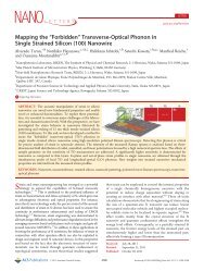
camera. Fig. 2 shows the <strong>in</strong>itial model selection and some<br />
frames obta<strong>in</strong>ed dur<strong>in</strong>g track<strong>in</strong>g.<br />
To evaluate our method, four metrics are used as expla<strong>in</strong>ed<br />
<strong>in</strong> Table I. We have done twenty experiments with<br />
the two <strong>IP</strong> cameras. The experiments are reported <strong>in</strong> Table<br />
II. Experiments are classified <strong>in</strong>to four classes based on the<br />
camera model, <strong>in</strong>itial model position from camera, and image<br />
resolution.<br />
B. Results<br />
We first present the results. Discussion follows <strong>in</strong> the next<br />
section. Fig.3 shows the d gp and d gc values for E 8 and E 14 .<br />
These distances allow us to verify if the tracker has lost the<br />
target, and if the target is near the ground-truth. If d gc is more<br />
than 1, target is lost (outside of FOV). For distances smaller<br />
than 0.6, the object is <strong>in</strong> the FOV, but for the range of (0.6 <<br />
d gc < 1), it depends if the centroid coord<strong>in</strong>ates of the target<br />
are <strong>in</strong>side the image.<br />
For E 8 , the target is always <strong>in</strong> the FOV. For E 14 , the target is<br />
lost several times between frame 59-80. For both experiments,<br />
d gp is small except when the target is lost. Table II shows<br />
the results of the five metrics with the system frame rate for<br />
all experiments. The algorithm is implemented on an Intel<br />
Xeon(R) 5150 <strong>in</strong> C++ us<strong>in</strong>g OpenCV. For d gc and d gp , we<br />
show the mean and variance of all experiments. For class 1<br />
and 3, because of the lower system frame rate, the method<br />
has lost the target several times, but eventually recovers. For<br />
experiments of class 1, the system frame rate is a little higher.<br />
Thus, there is fewer target lost (e.g. TF is smaller), less<br />
distance error (µ dgc and µ dgp ) and the results of precision<br />
are better (P is larger). Because of d EP and camera control,<br />
the error on µ dgc has effect on µ dgp and vice versa. For class<br />
2 and 4, the system frame rate is <strong>in</strong>creased because of smaller<br />
image size. T F for class 2 and 4 are smaller than class 1 and<br />
3. A faster system frame rate improves the results of T F , µ dgc ,<br />
µ dgp and P . ∆x m<strong>in</strong> and ∆x max <strong>in</strong> Table II are the m<strong>in</strong>imum<br />
and maximum length of target motion vector <strong>in</strong> number of<br />
pixels.<br />
In comparison of two Sony <strong>IP</strong> <strong>PTZ</strong> cameras, results from<br />
SNC-RZ50N (class 1 and class 2) are better than the results<br />
of SNC-RZ25N (class 3 and class 4).It is because of camera<br />
model, the SNC-RZ50N moves faster than SNC-RZ25N [19],<br />
[20].<br />
C. Discussion<br />
Results show that our algorithm can handle and overcome<br />
large motion (i.e. high values of ∆x max ) because of us<strong>in</strong>g<br />
a repetitive target detection scheme and a motion prediction<br />
technique that do not rely on spatial proximity. It will lose a<br />
target only if the target changes its motion direction suddenly<br />
and walks very fast <strong>in</strong> the opposite predicted position (e.g.<br />
experiments with T F ≠ 0). By us<strong>in</strong>g a repetitive detection<br />
scheme and comb<strong>in</strong><strong>in</strong>g it with a motion predictor, we can<br />
handle random motion between frames, as long as the target<br />
position is well predicted, and its appearance does not change<br />
significantly. The motion predictor is used to compensate<br />
the two delays τ 1 and τ 2 discussed <strong>in</strong> Section III, which<br />
may cause the target to exit the FOV. Small values of σ 2 d gp<br />
result from utiliz<strong>in</strong>g pyramidal Lucas Kanade optical flow<br />
for the motion extraction and comb<strong>in</strong><strong>in</strong>g it with a sampl<strong>in</strong>g<br />
method. This process of motion extraction with comb<strong>in</strong>ation<br />
of fuzzy classifier which uses color features to generate sample<br />
likelihood allow us to detect and track any mov<strong>in</strong>g objects.<br />
Generally, accord<strong>in</strong>g to the mean of distances, the location<br />
of the target is near to the ground-truth. The target is usually<br />
localized with<strong>in</strong> 1/4th of the image diagonal from the image<br />
center. With faster system frame rate the results of track<strong>in</strong>g<br />
have been improved significantly. In that case, we will have<br />
more frames to process. When localization fails, it is because<br />
of similarity or closeness of the color histogram of the target<br />
with other samples. The image resolution has effect on the<br />
system frame rate and thus on track<strong>in</strong>g error.<br />
In all experiments, there are scale changes to verify track<strong>in</strong>g<br />
aga<strong>in</strong>st scal<strong>in</strong>g. Our algorithm can overcome scal<strong>in</strong>g variations<br />
even <strong>in</strong> images with m<strong>in</strong>imum 5×5 face size(e.g. Fig.2(e) and<br />
(d)). It is because of us<strong>in</strong>g normalized color histogram and<br />
average color features. These two features are <strong>in</strong>dependent of<br />
the size of the target.<br />
Our method can also recover the track<strong>in</strong>g if it loses the<br />
object ( e.g. experiments with T F ≠ 0), because of the repetitive<br />
detection scheme. Of course, it is conditional to the object<br />
be<strong>in</strong>g <strong>in</strong> the FOV of the camera. Occlusions are handled <strong>in</strong><br />
the same way. However, when the object is occluded, another<br />
similar object will be tracked (the most likely sample) until the<br />
occlusion ends. This may cause the real target to become out<br />
of the FOV of the camera. Fig. 2 shows an example of shortterm<br />
occlusion handl<strong>in</strong>g. The proposed method can handle it<br />
<strong>in</strong> this case. In the reported experiments, occlusion did not<br />
cause difficulties. The duration of the experiments are short<br />
because the goal the algorithm will be zoom<strong>in</strong>g on target face<br />
and captur<strong>in</strong>g it for identification purpose.<br />
VI. CONCLUSION<br />
In this paper, an object track<strong>in</strong>g method is proposed and<br />
applied to human upper body track<strong>in</strong>g <strong>by</strong> <strong>IP</strong> <strong>PTZ</strong> camera<br />
<strong>in</strong> onl<strong>in</strong>e application. Human body track<strong>in</strong>g determ<strong>in</strong>es the<br />
location and size of each human body for each <strong>in</strong>put image<br />
of a video sequence. It can be used to get images of the<br />
face of a human target <strong>in</strong> different poses. It detects <strong>in</strong> every<br />
frame, candidate targets <strong>by</strong> extract<strong>in</strong>g mov<strong>in</strong>g objects us<strong>in</strong>g<br />
optical flow, and sampl<strong>in</strong>g around the image center. The target<br />
is detected among candidate target samples us<strong>in</strong>g a fuzzy<br />
classifier. Then, a movement command is sent to the camera<br />
us<strong>in</strong>g the target position and speed. Results show that our<br />
algorithm can handle and overcome large motion between two<br />
consecutive frames with low track fragmentation. Future work<br />
will be add<strong>in</strong>g camera zoom<strong>in</strong>g and enhanc<strong>in</strong>g robustness of<br />
the motion prediction to prevent the target from be<strong>in</strong>g out of<br />
the camera FOV.
(a) (b) (c) (d)<br />
(e) (f) (g) (h)<br />
Fig. 2. Examples of track<strong>in</strong>g frames for Exp 9 (a) to (d) and Exp 12 (e) to (h). Exp 9 (a) <strong>in</strong>itial model selection, (b) short-term occlusion, (c) after occlusion,<br />
(d) scale variation; Exp 12 (e) <strong>in</strong>itial model selection, (f) short-term occlusion, (g) after occlusion, (h) scale variation<br />
TABLE I<br />
EVALUATION METRICS.<br />
Metric<br />
P =<br />
T P<br />
T P +F P<br />
d gc =<br />
√ (xc−x g) 2 +(y c−y g) 2<br />
a<br />
√ (xp−x g) 2 +(y p−y g) 2<br />
Description<br />
to calculate the target localization accuracy<br />
to evaluate the dynamic performance of the track<strong>in</strong>g system; It is the spatial latency of the track<strong>in</strong>g system, as<br />
ideally, the target should be at the image center.<br />
d gp =<br />
2a<br />
to evaluate the error of the track<strong>in</strong>g algorithm. Ideally, d gp should be zero.<br />
T F = T OUT<br />
NF to <strong>in</strong>dicate the lack of cont<strong>in</strong>uity of the track<strong>in</strong>g system for a s<strong>in</strong>gle target track [18]<br />
T P : number of frames with target located correctly, F P :number of frames with target not located correctly, a: radius of circle which circumscribes the<br />
image, (x g,y g): ground-truth target coord<strong>in</strong>ates, (x c,y c): image center, (x p,y p): tracked object coord<strong>in</strong>ates, T OUT : number of frames with target out of FOV,<br />
NF : total number of frames.<br />
REFERENCES<br />
[1] D. Comaniciu, V. Ramesh, and P. Meer, “Kernel-based object track<strong>in</strong>g,”<br />
IEEE T-PAMI, vol. 25, no. 5, pp. 564–577, 2003.<br />
[2] I. Leichter, M. L<strong>in</strong>denbaum, and E. Rivl<strong>in</strong>, “Bittracker- a bitmap tracker<br />
for visual track<strong>in</strong>g under very general conditions,” IEEE T-PAMI, vol. 30,<br />
no. 9, pp. 1572–1588, 2008.<br />
[3] M. Roha, T. Kima, J. Park, and S. Lee, “Accurate object contour track<strong>in</strong>g<br />
based on boundary edge selection,” Pattern Recognition, vol. 40, no. 3,<br />
pp. 931–943, 2007.<br />
[4] J. H. Elder, S. Pr<strong>in</strong>ce, Y. Hou, M. Siz<strong>in</strong>tsev, and E. Olevsky, “Preattentive<br />
and attentive detection of humans <strong>in</strong> wide-field scenes,” International<br />
Journal of Computer Vision, vol. 72, no. 1, pp. 47–66, 2007.<br />
[5] D. Murray and A. Basu, “Motion track<strong>in</strong>g with an active camera,” IEEE<br />
Transactions on Pattern Analysis and Mach<strong>in</strong>e Intelligence, vol. 14, pp.<br />
449–459, 1994.<br />
[6] A. Yilmaz, X. Li, and M. Shah, “Contour-based object track<strong>in</strong>g with<br />
occlusion handl<strong>in</strong>g <strong>in</strong> video acquired us<strong>in</strong>g mobile cameras,” IEEE<br />
Transactions on Pattern Analysis and Mach<strong>in</strong>e Intelligence, vol. 26,<br />
no. 11, pp. 1531–1536, 2004.<br />
[7] S. Araki, N. Matsuoka, N. Yokoya, and H. Takemura, “Realtime<br />
track<strong>in</strong>g of multiple mov<strong>in</strong>g object contours <strong>in</strong> a mov<strong>in</strong>g camera image<br />
sequences,” IEICE Transaction on Information and Sytem, no. 7, pp.<br />
1581–1591, 2000.<br />
[8] C. Yang, R. Chen, C. Lee, and S. L<strong>in</strong>, “Ptz camera based position<br />
track<strong>in</strong>g <strong>in</strong> ip-surveillance system,” Int. Conf. on Sens<strong>in</strong>g Technology,<br />
pp. 142–146, 2008.<br />
[9] T. Funahashi, M. Tom<strong>in</strong>aga, T. Fujiwara, and H. Koshimizu, “Hierarchical<br />
face track<strong>in</strong>g <strong>by</strong> us<strong>in</strong>g ptz camera,” IEEE Int. Conf. on Automatic<br />
Face and Gesture Recognition (FGR), pp. 427–432, 2004.<br />
[10] K. Bernard<strong>in</strong>, F. Camp, and R. Stiefelhagen, “Automatic person detection<br />
and track<strong>in</strong>g us<strong>in</strong>g fuzzy controlled active cameras,” IEEE Conf. on<br />
Computer Vision and Pattern Recognition (CVPR), pp. 1–8, 2007.<br />
[11] Y. Li, H. Ai, T. Yamashita, S. Lao, and M. Kawade, “<strong>Track<strong>in</strong>g</strong> <strong>in</strong> low<br />
frame rate video: a cascade particle filter with discrim<strong>in</strong>ative observers<br />
of different life spans,” IEEE T-PAMI, vol. 30, no. 10, pp. 1728–1740,<br />
2008.<br />
[12] S. Kang, J. Paik, A. Koschan, B. Abidi, and M. Abidi, “Real-time<br />
video track<strong>in</strong>g us<strong>in</strong>g ptz cameras,” 6 th Int. Conf. on Quality Control <strong>by</strong><br />
Artificial Vision, pp. 103–111, 2003.<br />
[13] J. Y. Bouguet, “Pyramidal implementation of the lucas kanade feature<br />
tracker: Description of the algorithm,” Jean-YvesBouguet, 2002, kLT<br />
implementation <strong>in</strong> OpenCV.<br />
[14] J. Shi and C. Tomasi, “Good features to track,” IEEE Conf. on Computer<br />
Vision and Pattern Recognition (CVPR), pp. 593–600, 1994.<br />
[15] S. H. Cha and S. N. Srihari, “On measur<strong>in</strong>g the distance between<br />
histograms,” Pat. Recog., vol. 35, no. 6, pp. 1355–1370, 2002.<br />
[16] B. Boufama and M. Ali, “<strong>Track<strong>in</strong>g</strong> multiple people <strong>in</strong> the context<br />
of video surveillance,” Int. Conf. on Image Analysis and Recognition<br />
(ICIAR), pp. 581–592, 2007.<br />
[17] Sony corporation, “Snc-rz25n/p cgi command manual,” 2005, version<br />
1.0.<br />
[18] F. Y<strong>in</strong>, D. Makris, and S. Velast<strong>in</strong>, “Performance evaluation of object
(a) E 8 (b) E 14<br />
Fig. 3. d gc and d gp results for (a) E 8 and (b) E 14<br />
TABLE II<br />
EXPERIMENTAL RESULTS.<br />
P (%) T F (%) µ dgc σ 2 d gc<br />
µ dgp σ 2 d gp<br />
F R(fps) NF ∆x m<strong>in</strong> ∆x max IS IMP CM<br />
E 1 96 2.5 0.2849 0.0474 0.0785 0.0069 3.72 314 12 247 L N 50N<br />
E 2 97 1.8 0.3488 0.0359 0.0714 0.0064 3.71 308 5 189 L N 50N<br />
E 3 93 1.6 0.2182 0.0499 0.0411 0.0050 3.57 299 6 298 L F 50N<br />
E 4 92 2.4 0.3132 0.0559 0.0458 0.0028 3.76 283 1 543 L F 50N<br />
E 5 89 1.9 0.2903 0.0388 0.1154 0.0168 3.69 266 13 394 L M 50N<br />
class 1 97 2.04 0.2911 0.0456 0.0704 0.0076 3.68 1470 1 543 L A 50N<br />
E 6 95 0.7 0.1978 0.0285 0.0313 0.0012 7.31 703 8 231 S N 50N<br />
E 7 100 0 0.2581 0.0204 0.0485 0.0019 7.30 672 0 144 S N 50N<br />
E 8 96 0.1 0.1898 0.0227 0.0352 0.0015 7.22 686 2 112 S F 50N<br />
E 9 93 0.5 0.2667 0.0228 0.0496 0.0014 7.24 674 5 180 S F 50N<br />
E 10 90 0.4 0.2563 0.0261 0.0611 0.0080 7.14 641 2 235 S M 50N<br />
class 2 94.8 0.34 0.2337 0.0241 0.0451 0.0028 7.24 3376 0 235 S A 50N<br />
E 11 87 2.6 0.2565 0.0414 0.0727 0.0099 3.34 263 14 359 L N 25N<br />
E 12 89 2.7 0.3213 0.0472 0.0885 0.0127 3.30 260 10 207 L N 25N<br />
E 13 88 2.3 0.3253 0.0852 0.1261 0.0256 3.28 258 4 259 L F 25N<br />
E 14 90 1.9 0.3056 0.0384 0.0428 0.0069 3.33 252 6 275 L F 25N<br />
E 15 86 2.8 0.4692 0.1024 0.1254 0.0360 3.30 256 21 313 L M 25N<br />
class 3 87.9 2.46 0.3356 0.0629 0.0911 0.0182 3.30 1289 4 359 L A 25N<br />
E 16 92 1.3 0.2595 0.0348 0.0548 0.0019 7 623 7 272 S N 25N<br />
E 17 95 0.76 0.2536 0.0286 0.0348 0.0020 6.87 618 2 106 S N 25N<br />
E 18 100 0 0.2064 0.0306 0.1244 0.0409 6.76 619 0 109 S F 25N<br />
E 19 92 0.8 0.2246 0.0195 0.0954 0.0203 6.76 594 4 122 S F 25N<br />
E 20 93 0.6 0.3033 0.0259 0.0574 0.0026 6.92 611 6 111 S M 25N<br />
class 4 94.4 0.69 0.2495 0.0279 0.0734 0.0135 6.86 3065 0 272 S A 25N<br />
µ dgc : mean of d gc, µ dgp : mean of d gp, σ 2 d gc<br />
: variance of d gc, σ 2 d gp<br />
: variance of d gp, F R: <strong>System</strong> frame rate and ∆x m<strong>in</strong> and ∆x max: m<strong>in</strong>imum and<br />
maximum motion vector length, IS: Image Size, IMP: Initial model position from camera, N: Near, F: Far, M: Middle, L: 640 x 480, S: 320 x 240, A: All<br />
possible <strong>in</strong>itial model positions from camera, CM: <strong>Camera</strong> Model.<br />
track<strong>in</strong>g algorithms,” IEEE Int. Workshop on Performance Evaluation<br />
of <strong>Track<strong>in</strong>g</strong> and <strong>Surveillance</strong>(PETS), 2007.<br />
[19] Sony corporation, “Network camera- snc-rz50n, snc-rz50p,” 2005, http:<br />
//www.sony.ca/ip/brochures/ip cameras/SNCRZ50N%20Brochure.pdf,<br />
[<strong>Onl<strong>in</strong>e</strong>; accessed 21-September-2009].<br />
[20] ——, “Network camera- snc-rz25n,” 2005, http://www.sony.ca/<br />
ip/brochures/ip cameras/SNCRZ25N.pdf, [<strong>Onl<strong>in</strong>e</strong>; accessed 21-<br />
September-2009].