
Create successful ePaper yourself
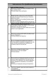
Turn your PDF publications into a flip-book with our unique Google optimized e-Paper software.
CRANEAGE: SLINGING - INTRODUCTION 1<br />
TRAINING MODULE<br />
SLINGING<br />
Modules 1 to 3<br />
NOTE: This is Part 1 of a 4-part<br />
module set covering Slinging.<br />
Part 2 covers Sections 4 to 7.<br />
Part 3 covers Sections 8 and 9.<br />
Part 4 covers Sections 10 to 12.<br />
Weights and C of G<br />
Tackle<br />
Included Angles
CRANEAGE: SLINGING - INTRODUCTION 1<br />
SLINGING<br />
Modules 1 to 3<br />
This Training Module comes to you courtesy of:<br />
<strong>Site</strong> <strong>Safe</strong> would like to acknowledge Fletcher Construction’s on-going support
CRANEAGE - SLINGING: BASICS PAGE 1<br />
CRANEAGE - SLINGING BASICS<br />
SECTION 1:<br />
WEIGHTS AND CENTRE OF GRAVITY<br />
1.1 Know the Load Weight<br />
1.2 Estimating Weights<br />
1.3 Weights of Common Materials<br />
1.4 Centre of Gravity 1<br />
1.5 Centre of Gravity 2<br />
1.6 Centre of Gravity 3
CRANEAGE - SLINGING: BASICS PAGE 2<br />
GOOD SLINGING PRACTICE<br />
BASIC RULES ... 1<br />
1.1 KNOW THE LOAD WEIGHT.<br />
Lifting any load with gear which is inadequate for the job is just not an<br />
option. Commonsense tells you this is dangerous.<br />
Before carrying out a lift, there are TWO factors which MUST be known:<br />
a) The weight of the object or material being lifted<br />
b) The lifting capacity of the tackle<br />
On the following sheets, are some simple formulas which will allow you to<br />
estimate the weights of most common materials on a construction site.<br />
Details of the lifting capacities of common <strong>slinging</strong> systems are shown in<br />
a separate section (Section 2).
CRANEAGE - SLINGING: ESTIMATING WEIGHTS<br />
PAGE 3<br />
GOOD SLINGING PRACTICE<br />
BASIC RULES ... 1<br />
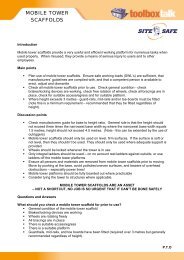
1.2 KNOW THE LOAD WEIGHT.<br />
L<br />
W<br />
RECTANGLE<br />
This applies for cubes and rectangles of any size.<br />
H<br />
L x W x H x wt./cu.m<br />
L<br />
SOLID CYLINDER<br />
(3.14 ÷ 4) x D x D x L x Wt./Cu.M.<br />
D<br />
D<br />
HEAVY WALL PIPE<br />
(3.14 ÷ 4) x D x D x L x Wt./Cu.M = Solid weight,<br />
MINUS<br />
(3.14 ÷ 4) x d x d x l x Wt./Cu.M = Hole weigh.<br />
Take the "hole" from the "solid" = Pipe weight!<br />
d<br />
C<br />
D<br />
THIN WALL PIPE<br />
Working this out is imagining that you have split the pipe<br />
lengthways, and have rolled it out into a flat sheet.<br />
3.14 x D x L x t x wt./cu.m.<br />
OR<br />
C x L x t x wt./cu.m<br />
t<br />
STEEL SECTIONS<br />
Any steel section can be divided into convenient<br />
sections, and the weight of each worked out. Add<br />
all the totals together, and you have the overall<br />
weight of the complete section.<br />
(This trick can also be used for<br />
any irregular-shaped object.)<br />
1<br />
e.g; an RSJ<br />
is three<br />
rectangles!<br />
2<br />
Wt. of 1 + Wt. of 2 + Wt. of 3 = Total weight.<br />
3
CRANEAGE - SLINGING: ESTIMATING WEIGHTS<br />
PAGE 4<br />
GOOD SLINGING PRACTICE<br />
BASIC RULES ... 1<br />
1.3 KNOW THE LOAD WEIGHT.<br />
A GUIDE TO WEIGHTS.<br />
STEEL BARS<br />
& RODS<br />
Dia.<br />
(mm)<br />
Approx. kg<br />
per metre<br />
WEIGHTS OF<br />
COMMON MATERIALS<br />
Material:<br />
Approx. kg. per<br />
cubic metre<br />
5<br />
0.15<br />
Aluminium<br />
2,645<br />
6<br />
0.22<br />
Asphalt<br />
1,410<br />
8<br />
0.40<br />
Blocks - conc.<br />
1,134<br />
10<br />
0.62<br />
Brick - common<br />
2,005<br />
12<br />
0.90<br />
Cement - loose<br />
1,506<br />
13<br />
1.05<br />
Concrete - plug<br />
2,305<br />
14<br />
1.20<br />
Concrete - reinf.<br />
2,405<br />
16<br />
1.60<br />
Copper<br />
8,950<br />
17<br />
1.80<br />
Earth - dry<br />
1,280<br />
18<br />
2.25<br />
Earth - wet<br />
1,600<br />
20<br />
2.45<br />
Glass sheet<br />
2,565<br />
22<br />
3.00<br />
Granite<br />
2,725<br />
24<br />
3.55<br />
Gravel - dry<br />
1,760<br />
25<br />
3.85<br />
Gravel - wet<br />
1,920<br />
28<br />
4.80<br />
Marble<br />
2,720<br />
30<br />
5.55<br />
Oils<br />
930<br />
32<br />
6.30<br />
Timber - dry<br />
810<br />
35<br />
7.55<br />
Timber - wet<br />
960<br />
40<br />
9.85<br />
Sand - dry<br />
1,730<br />
50<br />
12.50<br />
Sand - wet<br />
1,890<br />
100<br />
61.65<br />
Steel<br />
7,800<br />
150<br />
138.75<br />
Water<br />
1,000
CRANEAGE - SLINGING: ESTIMATING WEIGHTS<br />
PAGE 5<br />
GOOD SLINGING PRACTICE<br />
BASIC RULES ... 1<br />
1.4. KNOW HOW TO FIND THE CENTRE OF GRAVITY ... 1.<br />
Every load has a "centre of gravity".<br />
The "Centre of Gravity" of a load is a point which, if the load could be suspended from it, the<br />
load would be in perfect balance.<br />
In a simple rectanglar or square shape, the C of G is easily found, as the exact centre of the<br />
load. It gets a little more complicated with odd-shaped loads, but the following illustrations<br />
may make it a little easier.<br />
In a simple rectangle, the C of G is in the dead centre of the load, at a point where<br />
all the diagonals (from corner to corner) would intersect. A quick way is to divide<br />
the sides in half - the mid-point is the line of the C of G.<br />
Make sure the hook is over the centre of the load and it will be quite stable.<br />
Half the width will<br />
locate the C of G<br />
horizontally.<br />
=<br />
=<br />
=<br />
=<br />
Half the depth will<br />
locate the C of G<br />
vertically.<br />
=<br />
=<br />
The C of G for a cylinder or pipe is readily<br />
found, by halving the length. The C of G is<br />
on this line, on the centreline of the cylinder<br />
or pipe.<br />
The problems can arise where an irrgular-shaped load has to be<br />
lifted, which may require slings of different length, or the load on<br />
each sling may be markedly different.<br />
How to find the centres of gravity with these loads is covered on<br />
the following sheets.
PAGE 6<br />
GOOD SLINGING PRACTICE<br />
BASIC RULES ... 1<br />
1.5. KNOW HOW TO FIND THE CENTRE OF GRAVITY ... 2.<br />
The "Centre of Gravity" of a load is a point which, if the load could be suspended from it,<br />
the load would be in perfect balance.<br />
The crane hook needs to be directly over the centre of gravity, for the load to be stable.<br />
This load is not stable.<br />
The hook is over the<br />
centre of gravity, but<br />
the C of G is above the<br />
crane hook.<br />
This load is top-heavy,<br />
and could overturn<br />
while being craned.<br />
This load is<br />
stable. The<br />
hook is right<br />
over the<br />
load's centre<br />
of gravity.<br />
WHAT WILL HAPPEN....?<br />
UNSTABLE<br />
Hook is not over<br />
centre of gravity.<br />
The load will shift until the<br />
centre of gravity is under the<br />
hook.<br />
This will make landing the<br />
load very difficult, and could<br />
cause major problems in<br />
craneage.
CRANEAGE - SLINGING: ESTIMATING WEIGHTS<br />
PAGE 7<br />
GOOD SLINGING PRACTICE<br />
BASIC RULES ... 1<br />
1.6. KNOW HOW TO FIND THE CENTRE OF GRAVITY ... 3.<br />
A load that is not centred will swing as soon as it is lifted.<br />
This puts a greater stress on one sling, and can be dangerous.<br />
It becomes important to set the slings so the hook is right<br />
over the centre of gravity of the load, and this requires<br />
a bit of calculation.<br />
METHOD 1.<br />
In this case, the load is formed of two<br />
rectangles. The centre of gravity for each<br />
rectangle can easily be found, and the weight<br />
of the section estimated.<br />
Section 1 = 800kg; C of G = CG1.<br />
Section 2 = 1,200kg; C of G = CG2.<br />
Combined weight = 2,000kg.<br />
The larger section is (1200/2000), or 60% of<br />
the total load.<br />
Draw a line from CG1 to CG2, and measure it.<br />
Say it is 2.400 metres.<br />
60% of 2.400 m is 1.584 metres.<br />
The combined centre of gravity is then<br />
1.584 m from CG1. This is shown as CG3.<br />
The hook needs to be located over this point.<br />
800kg<br />
1 584<br />
CG1<br />
CG3<br />
2 400<br />
1200kg<br />
CG2<br />
METHOD 2<br />
Sometimes it seems possible to calculate<br />
the sling load stress on each side of a<br />
non-symmetrical load as shown, by using<br />
the normal sling formula and applying it<br />
twice: once for one side, and again for the<br />
other side, using two different lengths of<br />
sling and different heights.<br />
1 920<br />
1600 kg<br />
Heavily<br />
loaded<br />
sling<br />
This method is not accurate,<br />
especially with extreme load<br />
distribution such as a heavy<br />
steel structure on one end and<br />
light steel framing on the other<br />
end.<br />
400 kg<br />
CG1<br />
2 400<br />
CG2
CRANEAGE - SLINGING: BASICS PAGE 8<br />
CRANEAGE - SLINGING BASICS<br />
SECTION 2:<br />
KNOW YOUR TACKLE<br />
2.1 Know the Tackle Capacity<br />
2.2 The Riggers Chart - 1<br />
2.3 The Riggers Chart - 2<br />
2.4 Shackle Care<br />
2.5 Crane Hook Care<br />
2.6 Wedge Sockets<br />
2.7 Web Slinging Rights and Wrongs<br />
2.8 Web Slinging Capacity Details<br />
2.9 Blocks & Tackle 1<br />
2.10 Blocks & Tackle 2<br />
2.11 Blocks & Tackle 3
GOOD SLINGING PRACTICE<br />
BASIC RULES ... 2<br />
2.1 KNOW THE TACKLE CAPACITY<br />
Lifting any load with tackle which is inadequate for the job is just not an option.<br />
Commonsense tells you this is dangerous.<br />
Before carrying out any lift, there are TWO factors which MUST be known:<br />
The weight of the load, and<br />
The lifting capacity of the tackle.<br />
On the following sheets are some simple formulas which will show how to select the<br />
correct tackle for the job.<br />
Sheets 2.2 and 2.3 are quick-reference sheets for the common slings and shackles,<br />
with following sheets providing more detail, with information for checks of equipment,<br />
and the use of blocks and tackle.<br />
WLL 2.5T<br />
SWL 5.0 T
CRANEAGE - SLINGING: BASICS PAGE 10<br />
GOOD SLINGING PRACTICE<br />
BASIC RULES ... 2 - QUICK REFERENCE CHART 1<br />
POLYESTER ROUND SLINGS:<br />
LISTED CAPACITIES<br />
INDICATIVE ONLY.<br />
One stitch row = 1 tonne<br />
Vertical<br />
Choke<br />
Parallel<br />
Basket<br />
Basket<br />
90°<br />
All lifting tackle has the<br />
SWL or WLL marked.<br />
Slings must NOT be used<br />
beyond their 6-month<br />
inspection date.<br />
1.0<br />
2.0<br />
3.0<br />
4.0<br />
5.0<br />
6.0<br />
0.8<br />
1.6<br />
2.4<br />
3.2<br />
4.0<br />
4.8<br />
2.0<br />
4.0<br />
6.0<br />
8.0<br />
10.0<br />
12.0<br />
1.4<br />
2.8<br />
4.2<br />
5.6<br />
7.0<br />
8.1<br />
Nip angle<br />
must NOT<br />
exceed 120°,<br />
square or<br />
round reeved<br />
(choked).<br />
120°<br />
8.0<br />
6.4<br />
16.0<br />
11.2<br />
CHAIN SLINGS<br />
Grade 80, Lifting chain only.<br />
Chain<br />
dia. mm<br />
Single<br />
Vertical<br />
Single<br />
Reeved<br />
2-, 3- and 4- legged Slings<br />
Straight<br />
Reeved<br />
10 mm 3.2<br />
13 mm 5.4<br />
16 mm 8.0<br />
19 mm<br />
23 mm<br />
Rope<br />
dia. mm<br />
13 mm 2.0<br />
16 mm 3.0<br />
19 mm<br />
22 mm<br />
24 mm<br />
11.5<br />
16.9<br />
WIRE ROPE SLINGS<br />
Single<br />
Vertical<br />
4.3<br />
5.7<br />
6.8<br />
2.6<br />
4.3<br />
6.4<br />
9.2<br />
13.5<br />
Single<br />
Reeved<br />
1.6<br />
2.4<br />
3.4<br />
4.6<br />
5.4<br />
0° - 90° 90°-120°<br />
2.8<br />
4.2<br />
6.0<br />
8.0<br />
9.5<br />
Grade 1770, Fibre core<br />
2-, 3- and 4- legged Slings<br />
Straight<br />
2.0<br />
3.0<br />
4.3<br />
5.7<br />
6.8<br />
2.2<br />
3.4<br />
4.8<br />
6.4<br />
7.6<br />
Reeved<br />
26 mm 8.0 6.4 11.0 8.0 8.8 6.4<br />
28 mm 9.3 7.4 13.0 9.3 10.4 7.4<br />
4.5<br />
32 mm 12.1 9.7 16.9 12.1 13.5 9.7<br />
7.6<br />
11.3<br />
16.2<br />
23.9<br />
3.2<br />
5.4<br />
8.0<br />
11.5<br />
16.9<br />
0° - 90° 90°-120°<br />
7 mm 1.5 1.2 2.1 1.5<br />
1.7 1.2<br />
3.6<br />
6.0<br />
9.0<br />
12.9<br />
19.1<br />
2.6<br />
4.3<br />
6.4<br />
9.2<br />
13.5<br />
1.6<br />
2.4<br />
3.4<br />
4.6<br />
5.4
CRANEAGE - SLINGING: BASICS PAGE 11<br />
GOOD SLINGING PRACTICE<br />
BASIC RULES ... 2<br />
2.3. QUICK REFERENCE CHART 2<br />
BOW SHACKLES<br />
High Tensile<br />
Screw pin type.<br />
Size mm 10 11 13 16 19 22 25 28 32 35 38 45<br />
Pin Ø mm 11 13 16 19 22 25 28 32 35 38 42 50<br />
SWL<br />
1.0 1.5 2.0 3.25 4.15 6.5 8.0 9.5 12.0 13.5 17.0 25.0<br />
SWIFTLIFT PINS<br />
Min. 20MPa concrete.<br />
3 x depth = dist. from edge<br />
Pin length. mm<br />
SWL<br />
35 50 55 65 75 85 90 95 120<br />
0.47 0.88 1.17 1.51 1.88 2.1 2.42 2.92 4.16<br />
170<br />
5.00<br />
EFFECT OF INCLUDED ANGLE<br />
ON SLING LOADS<br />
WEIGHTS OF CONSTRUCTION<br />
MATERIALS<br />
0.5 t 0.5 t<br />
Load<br />
in<br />
tonnes<br />
30°<br />
60°<br />
0.52<br />
0.58<br />
Brick<br />
Concrete (wet)<br />
Concrete (& precast)<br />
Sand / Gravel (wet)<br />
Steel<br />
Timber<br />
Water<br />
T /Cu.M.<br />
2.01<br />
2.40<br />
2.41<br />
1.92<br />
7.85<br />
0.610<br />
1.00<br />
90°<br />
0.7<br />
120°<br />
1.0<br />
150° 2.0<br />
170°<br />
1 tonne load<br />
6.0<br />
CONCRETE WEIGHTS<br />
0.5 cu.m. skip<br />
1.4 t<br />
1.0 cu.m. skip<br />
2.7 t<br />
2.0 cu.m. skip<br />
5.6 t<br />
HOLLOW CORE FLOORING<br />
200 thk series<br />
0.32 t / m<br />
300 thk series<br />
0.42 t / m
CRANEAGE - SLINGING: BASICS PAGE 12<br />
GOOD SLINGING PRACTICE<br />
BASIC RULES ... 2<br />
2.4. CARE OF SHACKLES<br />
Shackle size is usually given<br />
as the pin diameter, not the<br />
bow diameter.<br />
NEVER use a bolt in place<br />
of a proper shackle pin. A<br />
bolt is made of the wrong<br />
(weaker) metal.<br />
Tie the pin to prevent it<br />
coming undone with<br />
twitching wire through the<br />
eye and around the<br />
opposite part of the bow.<br />
WLL 2.5 T<br />
Where possible, use a<br />
shackle with the pin on the<br />
hook, and not upside-down.<br />
A rope being pulled across a<br />
pin could cause it to come<br />
undone.<br />
ALWAYS use a shackle for<br />
vertical lifts only. If you have<br />
to use a shackle with two<br />
chokers spread at a wide<br />
angle, go UP a size in rating.<br />
CHECK for wear on the<br />
shackle bow. Any more<br />
than a 10% reduction in the<br />
bow material - throw the<br />
shackle out.<br />
CHECK FOR:<br />
Damaged threads<br />
Nicks or flat spots on pin<br />
Worn or damaged shoulder<br />
Bending in the pin<br />
Opening or closing-up of<br />
the bow gap<br />
Flat spots on bow<br />
Wear on bow<br />
Eyes out of alignment<br />
WLL 2.5 T<br />
A pin should have ONE thread showing<br />
when tight.<br />
Any more or any less - the shackle has<br />
distorted and should be scrapped.
CRANEAGE - SLINGING: BASICS PAGE 13<br />
GOOD SLINGING PRACTICE<br />
BASIC RULES ... 2<br />
2.5. CRANE HOOK CHECK AREAS<br />
CHECK<br />
the swivel<br />
is working<br />
smoothly<br />
CHECK<br />
for signs<br />
of cracks<br />
and<br />
twisting<br />
CHECK for<br />
wear and<br />
cracks<br />
CHECK for<br />
wear and<br />
deformation<br />
CHECK for<br />
signs<br />
of the throat<br />
opening up<br />
CHECK<br />
the<br />
safety<br />
latch<br />
CHECK<br />
the hook<br />
rating<br />
is clearly<br />
shown<br />
CHECK<br />
for<br />
twisting<br />
ANY sign of a defect means the<br />
hook could be dangerous if used.<br />
DO NOT risk using it - have it<br />
checked over by our experts. Tag it<br />
as being "FAULTY".<br />
Other suspicious signs to check for:<br />
- Discolouration through heat.<br />
- Any signs of welding.<br />
- Any sign of the hook rating being altered or obscured.<br />
- Any sign of the hook having contact with power (arced areas)<br />
- Any deformations, even hammer marks, on the hook.<br />
YOU MAY BE THE ONE UNDER THE HOOK IF IT FAILS.<br />
YOU DON'T GET SECOND CHANCES.
CRANEAGE - SLINGING: BASICS PAGE 14<br />
GOOD SLINGING PRACTICE<br />
BASIC RULES ... 2<br />
2.6. WEDGE SOCKET CHECKS<br />
The wedge socket<br />
MUST be attached with<br />
the load line pulling in a<br />
straight line from the<br />
pin.<br />
RIGHT!<br />
WRONG!!<br />
METHODS OF SECURING THE DEAD END<br />
Always pull sufficient rope through the socket.<br />
The dead end is clamped to the<br />
load line - NOT too tight, or the<br />
load line may be damaged.<br />
Always allow a little slack.<br />
After loading the socket, the<br />
dogging clamp should be<br />
released and some slack<br />
forced into the dead end,<br />
otherwise the dogging clamp<br />
takes all the load until it fails.<br />
(A)<br />
Saddle on live end<br />
This is a common method -<br />
clamp a short length of line<br />
to the dead end.<br />
(B)<br />
Take care if<br />
considering this<br />
method - the loop<br />
can often snag on<br />
projecting materials.<br />
(C)
CRANEAGE - SLINGING: BASICS PAGE 15<br />
GOOD SLINGING PRACTICE<br />
BASIC RULES ... 2<br />
2.7. WEB SLINGING<br />
SWL 10 T WITH 6M SLINGS<br />
Lifting Beam<br />
10,000kg LOAD<br />
RIGHT!!<br />
This is the correct way<br />
to sling precast using<br />
mesh or nylon slings.<br />
Note the slings are<br />
vertical and the full<br />
width of the sling is<br />
taking the load.<br />
The greater the included angle,<br />
the greater the risk.<br />
10,000kg LOAD<br />
WRONG!!<br />
This is a common - and risky - method<br />
of <strong>slinging</strong>. The only thing preventing<br />
the slings being pulled together, is<br />
friction between the webbing and the<br />
load.<br />
The entire load is being<br />
borne by a thin edge of the<br />
sling. Failure is certain.<br />
Side force:<br />
2 900 kg @ 60° incl. angle<br />
5 000 kg @ 90° incl. angle<br />
The sling will<br />
tear at this point.<br />
FACTORS INVOLVED:<br />
1. Load is applied to the sling edge only. It<br />
must be shared by the entire sling width.<br />
2. The slings are being pulled in together<br />
by the weight of the load (Side force).<br />
3. If slipping starts, the slings will be destroyed<br />
by both abrasive friction, and heat.<br />
4. Once slipping starts, it cannot be halted.
CRANEAGE - SLINGING: BASICS PAGE 16<br />
GOOD SLINGING PRACTICE<br />
BASIC RULES ... 2<br />
2.8. WEB SLINGING<br />
FLAT EYE<br />
Used where<br />
minimum<br />
clearance is<br />
required<br />
for passing under<br />
load, and for use<br />
with lifting beams.<br />
REDUCED<br />
EYE<br />
For use with<br />
small hooks.<br />
REDUCED AND<br />
REVERSED<br />
EYE<br />
For choker lift,<br />
giving square lift<br />
to the load on the<br />
same plane as<br />
the webbing.<br />
METAL DEE<br />
(Plain and Choker)<br />
Best suited to lifts<br />
where the eye is<br />
subject to heavy<br />
wear.<br />
SAFE WORKING CAPACITY (S.W.L.) IN TONNES<br />
Slings as above<br />
Endless Slings<br />
Sling<br />
Width:<br />
No. of<br />
Plys<br />
38mm<br />
One<br />
Two<br />
0.75<br />
1.50<br />
0.60<br />
1.20<br />
1.05<br />
2.10<br />
1.50<br />
3.00<br />
1.50<br />
3.00<br />
1.20<br />
2.40<br />
2.10<br />
4.20<br />
3.00<br />
6.00<br />
50mm<br />
One<br />
Two<br />
1.00<br />
2.00<br />
0.80<br />
1.60<br />
1.40<br />
2.80<br />
2.00<br />
4.00<br />
2.00<br />
4.00<br />
1.60<br />
3.20<br />
2.80<br />
5.60<br />
4.00<br />
8.00<br />
75mm<br />
One<br />
Two<br />
1.50<br />
3.00<br />
1.20<br />
2.40<br />
2.10<br />
4.20<br />
3.00<br />
6.00<br />
3.00<br />
6.00<br />
2.40<br />
4.80<br />
4.20<br />
8.40<br />
6.00<br />
12.00<br />
100mm<br />
One<br />
Two<br />
2.00<br />
4.00<br />
1.60<br />
3.20<br />
2.80<br />
5.60<br />
4.00<br />
8.00<br />
4.00<br />
8.00<br />
3.20<br />
6.40<br />
5.60<br />
11.20<br />
8.00<br />
16.00<br />
150mm<br />
One<br />
Two<br />
3.00<br />
6.00<br />
2.40<br />
4.80<br />
4.20<br />
8.40<br />
6.00<br />
12.00<br />
6.00<br />
12.00<br />
4.80<br />
9.60<br />
8.40<br />
16.80<br />
12.00<br />
24.00<br />
200mm<br />
One<br />
Two<br />
4.00<br />
8.00<br />
3.20<br />
6.40<br />
5.60<br />
11.20<br />
8.00<br />
16.00<br />
8.00<br />
16.00<br />
6.40<br />
12.80<br />
11.20<br />
22.40<br />
16.00<br />
32.00<br />
300mm<br />
One<br />
Two<br />
6.00<br />
12.00<br />
4.80<br />
9.60<br />
8.40<br />
16.80<br />
12.00<br />
24.00<br />
Special endless slings<br />
available to specific design.
CRANEAGE - SLINGING: BASICS PAGE 17<br />
GOOD SLINGING PRACTICE<br />
BASIC RULES ... 2<br />
2.9. BLOCKS AND TACKLE ... 1<br />
A load of 500 kg is<br />
going to need a force of<br />
500 kg to shift it. Those<br />
TWO loads will be<br />
applied to the block<br />
rigging.<br />
Load on block rigging:<br />
(500 kg + 500 kg) = 1,000 kg!<br />
500 kg<br />
A snatch block is rated by<br />
the maximum line pull.<br />
Therefore, a 500 kg snatch<br />
block will have a 1,000 kg<br />
capacity hook.<br />
500 kg<br />
Load: 500kg<br />
The greater the included angle between the load rope and the pulling rope, the less the<br />
force on the block rigging.<br />
Yes, this is the opposite to slings, and can be confusing, BUT it is very important to<br />
remember the difference, and WHY that difference works.<br />
920 kg 705 kg 500 kg<br />
500 kg<br />
500 kg 500 kg<br />
500 kg 500 kg<br />
500 kg<br />
45° 90° 135°<br />
In a vertical,lift, the combined force of both the load AND the lifting force are applied to<br />
the block. If the load was being pulled at 180° - in effect a straight rope - the block<br />
would take NO load. The load on the block then decreases, as the included angle<br />
increases.<br />
The following sheet shows how these forces can be worked out, for a number of<br />
angles. All you need to do, is MULTIPLY the load by the factor shown for the nearest<br />
angle between the load line and lead line ("pulling" line).
CRANEAGE - SLINGING: BASICS PAGE 18<br />
GOOD SLINGING PRACTICE<br />
BASIC RULES ... 2<br />
2.10. BLOCKS AND TACKLE ... 2<br />
TABLE OF MULTIPLICATION FACTORS FOR<br />
SNATCH BLOCK LOADS<br />
Angle between<br />
Lead and Load<br />
Lines<br />
Multiplication<br />
Factor<br />
10°<br />
20°<br />
30°<br />
1.99<br />
1.97<br />
1.93<br />
Lifting<br />
force<br />
Load<br />
40°<br />
1.87<br />
Angle:<br />
50°<br />
1.81<br />
60°<br />
1.73<br />
70°<br />
1.64<br />
80°<br />
1.53<br />
90°<br />
1.41<br />
100°<br />
1.29<br />
110°<br />
1.15<br />
120°<br />
1.00<br />
130°<br />
0.84<br />
140°<br />
0.68<br />
150°<br />
0.52<br />
160°<br />
0.35<br />
170°<br />
0.17<br />
180°<br />
0.00<br />
Examples:<br />
A load of 645 kg is to be shifted using a snatch block. The angle between the lead line<br />
and the load line is 80°. What force will be applied to the snatch block rigging?<br />
= (645 x 1.53) = 986.85 kg , say 987 kg.<br />
A load of 362 kg is to be shifted, with the angle between lines at 75°. What is the force<br />
applied to the block rigging?<br />
Here, you take a factor half-way between the 70° and 80° factors and use that.<br />
= (362 x 1.59) = 575.58 kg, say 576 kg.
CRANEAGE - SLINGING: BASICS PAGE 19<br />
GOOD SLINGING PRACTICE<br />
BASIC RULES ... 2<br />
2.11. BLOCKS AND TACKLE ... 3<br />
"What is meant by mechanical advantage?"<br />
"Mechanical advantage" is a term to describe how<br />
any machine multiplies the force applied to it in order<br />
to lift or move a load.<br />
With a block and tackle, using a rope through several<br />
pulleys or sheaves, a large load can be lifted or<br />
moved with only a small effort.<br />
Diag. 1<br />
The top fixed sheaves, which do not travel up or<br />
down, serve no other purpose than to change the<br />
direction of the rope. The sheaves on the travelling<br />
block - the lower block - will create a mechanical<br />
advantage of 2:1 on each sheave.<br />
(Not counted)<br />
2<br />
3<br />
1<br />
4<br />
To calculate the mechanical advantage of a block<br />
system, simply count the number of lines supporting the<br />
load - except for the lead line (the one you pull on) when<br />
it comes down over the top block.<br />
Diagram 1 at right shows this set-up.<br />
Mechanical advantage is 4:1, which means that, to lift a<br />
load of 400 kg, an effort of only 100 kg is required on the<br />
lead line.<br />
However, if the lead line comes up to the<br />
winch or lifting force, it is counted as a<br />
supporting line, and the mechanical<br />
advantage in this case - as shown in<br />
Diagram 2 - becomes 5:1, which means<br />
that, for the same 400 kg load, only 80 kg<br />
of effort is required.<br />
Diag. 2<br />
1<br />
4 5<br />
2<br />
3
CRANEAGE - SLINGING: BASICS PAGE 20<br />
CRANEAGE - SLINGING BASICS<br />
SECTION 3:<br />
KNOW ABOUT INCLUDED ANGLES<br />
3.1 Know about the "Included Angle"<br />
3.2 Effect of Included Angle on Sling Loads<br />
3.3 Load Angle Factors<br />
3.4 Finding the Included Angle
CRANEAGE - SLINGING: BASICS PAGE 21<br />
GOOD SLINGING PRACTICE<br />
BASIC RULES ... 3<br />
3.1. KNOW WHAT THE "INCLUDED ANGLE" IS ALL ABOUT.<br />
You know the weight of the load to be lifted.<br />
You have estimated the load's centre of gravity.<br />
You know what loads the slings can carry.<br />
You have information on the different types of slings.<br />
You are all set to lift, then. Right?<br />
No!<br />
There is still one very important factor to take into account - the "Included Angle" of<br />
the slings.<br />
Having the angle of the slings is so important that it gets a section all of its own.<br />
The included angle is the angle<br />
between the two legs of a sling system.<br />
The greater the included angle<br />
between sling legs, the less load can<br />
be lifted.<br />
If a single sling is taking a load<br />
vertically, the load on that sling is<br />
equal to the load weight. That's<br />
quite simple, and certainly<br />
sounds logical.<br />
1,000 kg<br />
It may sound odd, but if a sling<br />
has an angle between the sling<br />
legs of 150°, each sling leg will<br />
have a load equal to twice the<br />
total load weight.<br />
For a load of 1,000 kg, each sling<br />
will have a load of 2,000 kg.<br />
Sling load =<br />
2,000 kg<br />
1,000 kg<br />
Incl. angle =<br />
150°<br />
Should that angle increase to<br />
170°, each leg will be subject to<br />
a load that is six times the total<br />
load weight.<br />
For a load of 1,000 kg, each sling<br />
will be loaded with 6,000 kg.<br />
Sling load =<br />
6,000 kg<br />
1,000 kg<br />
Incl. angle =<br />
170°
CRANEAGE - SLINGING: BASICS PAGE 22<br />
GOOD SLINGING PRACTICE<br />
BASIC RULES ... 3<br />
3.2. THE EFFECT OF THE "INCLUDED ANGLE" ON SLING LOADS.<br />
30°<br />
520<br />
520<br />
60°<br />
580<br />
580<br />
90°<br />
700 700<br />
120°<br />
1000<br />
1000<br />
2000<br />
150°<br />
2000<br />
6000<br />
170°<br />
6000<br />
1000 kg load<br />
This shows the effect of increasing the included angle in slings.You<br />
will see that, with an included angle of 170°, the load on each sling<br />
is six times the actual weight being lifted.<br />
Do NOT exceed the 120° included angle which provides each sling<br />
with the same weight as the actual load.
Vert<br />
CRANEAGE - SLINGING: BASICS PAGE 23<br />
GOOD SLINGING PRACTICE<br />
BASIC RULES ... 3<br />
3.3. INCLUDED ANGLE FACTORS ON SLING LOADS.<br />
12,000<br />
11,000<br />
10,000<br />
This simple graph shows the dramatic increase in loading of<br />
slings as the included angle increases.<br />
It can be seen that an included angle of less than 120°<br />
is the best option.<br />
(BASED ON TWO SLINGS LIFTING A LOAD OF 2,000 KG.)<br />
9,000<br />
8,000<br />
7,000<br />
6,000<br />
5,000<br />
4,000<br />
3,000<br />
2,000<br />
1,000<br />
10 0<br />
20 0<br />
30 0<br />
40 0<br />
50 0<br />
60 0<br />
70 0<br />
80 0<br />
90 0<br />
INCLUDED ANGLE<br />
100 0<br />
110 0<br />
120 0<br />
130 0<br />
140 0<br />
150 0<br />
160 0<br />
170 0<br />
SLING<br />
LOAD<br />
IN KGs<br />
Actual load<br />
on sling<br />
1,154<br />
C L<br />
60°<br />
Angle off<br />
horizontal:<br />
Included<br />
angle of<br />
sling:<br />
Sling<br />
included<br />
angle:<br />
Load<br />
angle<br />
factor:<br />
1,414<br />
2,000<br />
2,924<br />
5,714<br />
11,490<br />
2,000 kg load<br />
45°<br />
30°<br />
20°<br />
10°<br />
5°<br />
60°<br />
90°<br />
120°<br />
140°<br />
160°<br />
170°<br />
170° 11,490<br />
160°<br />
150°<br />
140°<br />
130°<br />
120°<br />
110°<br />
100°<br />
90°<br />
80°<br />
70°<br />
60°<br />
50°<br />
40°<br />
30°<br />
20°<br />
10°<br />
5,714<br />
3,861<br />
2,924<br />
2,364<br />
2,000<br />
1,742<br />
1,555<br />
1,414<br />
1,305<br />
1,221<br />
1,155<br />
1,104<br />
1,064<br />
1,035<br />
1,015<br />
1,004
PAGE 24<br />
GOOD SLINGING PRACTICE<br />
BASIC RULES ... 3<br />
3.4. FINDING THE INCLUDED ANGLE.<br />
How do you work out or measure the "included angle" in a set of slings?<br />
As you will now be aware, an included angle of more than 120° is not an option. The<br />
stresses on the sling start to increase dramatically once the angle of 120° is exceeded.<br />
It is a <strong>good</strong> <strong>practice</strong> to keep the sling included angle at a maximum of 60°.<br />
60° is obtained when (L) - the distance between sling attachments - is<br />
EQUAL to (S) - the sling length.<br />
90° is obtained when L is 1.4 times S.<br />
120° is obtained when L is 1.7 times S.<br />
Included<br />
Angle:<br />
S<br />
L