Duct Testing Standard - Energy Program - Washington State University
Duct Testing Standard - Energy Program - Washington State University
Duct Testing Standard - Energy Program - Washington State University
You also want an ePaper? Increase the reach of your titles
YUMPU automatically turns print PDFs into web optimized ePapers that Google loves.
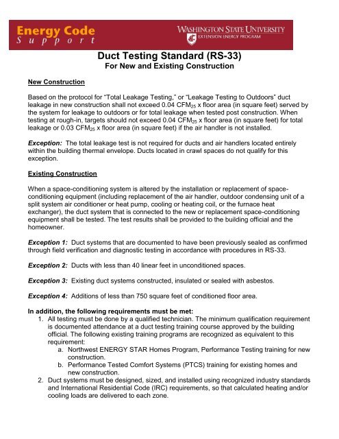
<strong>Duct</strong> <strong>Testing</strong> <strong>Standard</strong> (RS-33)<br />
For New and Existing Construction<br />
New Construction<br />
Based on the protocol for “Total Leakage <strong>Testing</strong>,” or “Leakage <strong>Testing</strong> to Outdoors” duct<br />
leakage in new construction shall not exceed 0.04 CFM 25 x floor area (in square feet) served by<br />
the system for leakage to outdoors or for total leakage when tested post construction. When<br />
testing at rough-in, targets should not exceed 0.04 CFM 25 x floor area (in square feet) for total<br />
leakage or 0.03 CFM 25 x floor area (in square feet) if the air handler is not installed.<br />
Exception: The total leakage test is not required for ducts and air handlers located entirely<br />
within the building thermal envelope. <strong>Duct</strong>s located in crawl spaces do not qualify for this<br />
exception.<br />
Existing Construction<br />
When a space-conditioning system is altered by the installation or replacement of spaceconditioning<br />
equipment (including replacement of the air handler, outdoor condensing unit of a<br />
split system air conditioner or heat pump, cooling or heating coil, or the furnace heat<br />
exchanger), the duct system that is connected to the new or replacement space-conditioning<br />
equipment shall be tested. The test results shall be provided to the building official and the<br />
homeowner.<br />
Exception 1: <strong>Duct</strong> systems that are documented to have been previously sealed as confirmed<br />
through field verification and diagnostic testing in accordance with procedures in RS-33.<br />
Exception 2: <strong>Duct</strong>s with less than 40 linear feet in unconditioned spaces.<br />
Exception 3: Existing duct systems constructed, insulated or sealed with asbestos.<br />
Exception 4: Additions of less than 750 square feet of conditioned floor area.<br />
In addition, the following requirements must be met:<br />
1. All testing must be done by a qualified technician. The minimum qualification requirement<br />
is documented attendance at a duct testing training course approved by the building<br />
official. The following existing training programs are recognized as equivalent to this<br />
requirement:<br />
a. Northwest ENERGY STAR Homes <strong>Program</strong>, Performance <strong>Testing</strong> training for new<br />
construction.<br />
b. Performance Tested Comfort Systems (PTCS) training for existing homes and<br />
new construction.<br />
2. <strong>Duct</strong> systems must be designed, sized, and installed using recognized industry standards<br />
and International Residential Code (IRC) requirements, so that calculated heating and/or<br />
cooling loads are delivered to each zone.
Total <strong>Duct</strong> Leakage Test<br />
<strong>Testing</strong> Procedure Application:<br />
This test is appropriate in new construction when ducts are to be tested at the rough-in stage<br />
before the house envelope is intact and can also be done post construction. The test measures<br />
the total collected leaks in the system at an induced pressure of 25 Pascals (PA). Compared to<br />
the leakage to exterior test, the total leakage test is simpler, but does not discriminate between<br />
leakage to inside and outside the heated space; as such, this test is not recommended for<br />
homes with complete house envelopes and HVAC systems. In such cases, the leakage to<br />
outside test is recommended.<br />
<strong>Standard</strong>:<br />
1) For certification, the measured duct leakage must not exceed 0.04 CFM 25 x floor area (in<br />
square feet) served by the system at rough-in when the air handler is installed.<br />
2) The measured duct leakage at rough-in must not exceed 0.03 CFM 25 x floor area (in square<br />
feet) served by the system when the air handler is not installed.<br />
3) If testing post construction, the total leakage must not exceed 0.04 CFM 25 x floor area (in<br />
square feet) served by the system.
Example - For a 2240 Ft. 2 home:<br />
Total leakage target 2240 X .04 = 90 CFM<br />
Leakage to exterior target 2240 X .04 = 90 CFM<br />
Tools and Equipment:<br />
<strong>Duct</strong> testing device<br />
Manometer<br />
Tape and paper or duct mask to seal registers<br />
Setup:<br />
Ensure air handler does not operate during test.<br />
Remove air filters from the air handler.<br />
Open all duct dampers (Note setting and return after testing).<br />
Attach the duct testing device to the air handler cabinet (preferred location), or:<br />
o Attach the duct testing device to the return register closest to the air handler.<br />
Place the duct pressure tap in the supply register closest to the air handler, or<br />
o Place the duct tap in the supply plenum.<br />
Seal all the duct system supply and return registers with tape, paper, or mask.<br />
If the duct testing equipment is not located outside of conditioned space, open an exterior<br />
door or window to insure all spaces exterior to the ducts are at outside pressure.<br />
Install a flow ring which you think best matches the needed capacity of the fan and will<br />
provide a duct system pressure of over 25 Pa (see duct testing equipment manual).<br />
Test:<br />
1. With the duct testing device, pressurize the ducts to +25 Pascals with respect to<br />
(WRT) outside (see Figure 1).<br />
1. With the duct tester, pressurize<br />
pressurize the ducts to the 25 ducts Pa WRT to +25 Outdoors PA<br />
WRT (Channel Outdoors A, Green) (channel A)<br />
AH<br />
+ 25<br />
A B<br />
.<br />
A<br />
B<br />
Figure 1: Pressurizing the duct system
2. Determine the duct leakage (with simple manometers, the fan pressure (Pa) is converted to<br />
CFM 25 using a flow table. Many digital manometers sold with duct testing equipment can<br />
automatically perform this conversion, and display CFM 25 directly.) Consult your duct testing<br />
equipment manual (see Figure 2).<br />
Note: You may need to adjust the ring size of the duct testing device (see duct testing<br />
equipment manual).<br />
2. Read the Fan Pressure/Flow<br />
(Channel B, Red).<br />
+ 66.<br />
AH<br />
A<br />
A B<br />
B<br />
Figure 2: Determining duct leakage
<strong>Duct</strong> Leakage to the Exterior Test<br />
<strong>Testing</strong> Procedure Application:<br />
In new construction, doors and windows must be installed and the building envelope capable of<br />
maintaining +25 Pascals WRT outside pressure with the operation of a blower door. By<br />
pressurizing the interior of the home with a blower door while using a duct testing device, duct<br />
leakage to the interior is eliminated from the measurement. The test is designed to measure the<br />
CFM 25 value for leakage in the duct system to outside of the conditioned space.<br />
<strong>Standard</strong>: The measured duct leakage must not exceed 0.04 CFM 25 x floor area (in square<br />
feet) served by the system.<br />
Tools and Equipment:<br />
Blower Door<br />
<strong>Duct</strong> testing device.<br />
Manometer (a second manometer is helpful, but not required)<br />
Tape and paper or duct mask to seal registers.<br />
Setup:<br />
Example 1. <strong>Duct</strong> testing device is hooked up at largest return register. The duct testing<br />
equipment is inside the pressurized zone of the house when the blower door is turned on.<br />
Prepare house for a standard blower door test.<br />
<br />
<br />
Set up blower door and set to pressurize the house.<br />
Set up the duct testing device as in a total leakage test except all exterior doors and<br />
windows must be closed.<br />
Test:<br />
1. Using the blower door, pressurize the interior to +25 PA WRT outdoors (see Figure 3).<br />
1. Using the blower door, pressurize<br />
the interior to 25 Pa WRT<br />
Outdoors (Channel A, Green)<br />
+ 25.<br />
A B<br />
A<br />
B<br />
Figure 3: Pressurizing interior to +25 PA WRT outdoors.
2. With the duct testing device, pressurize the ducts to + 25 PA WRT outdoors, or<br />
o With the duct testing device, pressurize the ducts to 0 PA WRT interior (see<br />
Figure 4).<br />
2. With the duct testing device, pressurize<br />
the ducts to 25 Pa WRT Outdoors<br />
(Channel A, Green)<br />
AH<br />
+ 25<br />
A<br />
A B<br />
B<br />
or<br />
2a. With the duct testing device, pressurize<br />
the ducts to 0 Pa WRT Interior<br />
(Channel A, Green)<br />
0<br />
AH<br />
A<br />
A B<br />
B<br />
Figure 4: Pressurizing ducts to +25 PA WRT outdoors, or 0 PA WRT Indoors. (<strong>Duct</strong><br />
testing device hooked up to largest return duct, inside the pressurized zone of the<br />
house).
3. Check the blower door reading to assure it is still at +25PA.<br />
4. Determine the duct leakage (with simple manometers, the fan pressure (Pa) is converted to<br />
CFM25 using a flow table. Many digital manometers sold with duct testing equipment can<br />
automatically perform this conversion, and display CFM25 directly.) Consult your duct<br />
testing equipment manual (see Figure 5).<br />
Note: You may need to adjust the ring size of the duct testing device (see duct testing<br />
equipment manual).<br />
3. Read the fan pressure/flow<br />
(Channel B, Red)<br />
66<br />
AH<br />
A<br />
A B<br />
B<br />
Figure 5: Determining duct leakage.
Example 2. <strong>Duct</strong> testing device is hooked up at air handler. Depending on the location of the<br />
air handler, the duct testing device may be either inside or outside the pressurized zone of the<br />
house. (Air handler is “Outside” in Figures 6, 7, 8). Follow the same steps as in Example 1.<br />
1. Using the blower door, pressurize<br />
the interior to 25 Pa WRT<br />
Outdoors (Channel A, Green)<br />
+ 25.<br />
A B<br />
A<br />
B<br />
Figure 6: Pressurizing interior to +25 PA WRT outdoors<br />
+ 25.<br />
2. With the duct tester, pressurize<br />
the ducts to +25 Pa WRT Outdoors<br />
(Channel A, Green)<br />
A B<br />
A<br />
B<br />
Figure 7: Pressurizing ducts to +25 PA WRT outdoors (duct testing device located<br />
outside the pressurized zone of the house).
+ 66.<br />
3. Read the fan pressure/flow<br />
(Channel B, Red).<br />
A B<br />
A<br />
B<br />
Figure 8: Determining duct leakage<br />
Note: When the duct testing device is outside of the pressurized zone of the house, it is no<br />
longer necessary to run a pressure tube from the reference pressure tap on channel A to the<br />
outside when determining the duct pressure WRT to outside as it was in Example 1.<br />
© 2012 <strong>Washington</strong> <strong>State</strong> <strong>University</strong> Extension <strong>Energy</strong> <strong>Program</strong>. This publication contains material written and produced for<br />
public distribution. Permission to copy or disseminate all or part of this material is granted, provided that the copies are not<br />
made or distributed for commercial advantage, and that each is referenced by title with credit to the <strong>Washington</strong> <strong>State</strong><br />
<strong>University</strong> Extension <strong>Energy</strong> <strong>Program</strong>. Copying, reprinting or dissemination, electronic or otherwise, for any other use<br />
requires prior written permission from the <strong>Washington</strong> <strong>State</strong> <strong>University</strong> Extension <strong>Energy</strong> <strong>Program</strong>. WSUEEP-09-008 Rev. 1<br />
2012.


