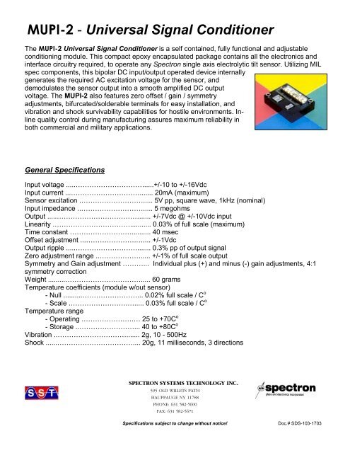
MUPI-2 - Universal Signal Conditioner
MUPI-2 - Universal Signal Conditioner
MUPI-2 - Universal Signal Conditioner

You also want an ePaper? Increase the reach of your titles
YUMPU automatically turns print PDFs into web optimized ePapers that Google loves.
<strong>MUPI</strong>-2 - <strong>Universal</strong> <strong>Signal</strong> <strong>Conditioner</strong><br />
The <strong>MUPI</strong>-2 <strong>Universal</strong> <strong>Signal</strong> <strong>Conditioner</strong> is a self contained, fully functional and adjustable<br />
conditioning module. This compact epoxy encapsulated package contains all the electronics and<br />
interface circuitry required, to operate any Spectron single axis electrolytic tilt sensor. Utilizing MIL<br />
spec components, this bipolar DC input/output operated device internally<br />
generates the required AC excitation voltage for the sensor, and<br />
demodulates the sensor output into a smooth amplified DC output<br />
voltage. The <strong>MUPI</strong>-2 also features zero offset / gain / symmetry<br />
adjustments, bifurcated/solderable terminals for easy installation, and<br />
vibration and shock survivability capabilities for hostile environments. Inline<br />
quality control during manufacturing assures maximum reliability in<br />
both commercial and military applications.<br />
General Specifications<br />
Input voltage .....………………………….....+/-10 to +/-16Vdc<br />
Input current ...…………………………....... 20mA (maximum)<br />
Sensor excitation .………………………..... 5V pp, square wave, 1kHz (nominal)<br />
Input impedance ..………………………..... 5 megohms<br />
Output .....………………………………...... +/-7Vdc @ +/-10Vdc input<br />
Linearity .……………………………........... 0.03% of full scale (maximum)<br />
Time constant ……………………….......... 40 msec<br />
Offset adjustment ...………………….….... +/-1Vdc<br />
Output ripple .....………………………....... 0.3% pp of output signal<br />
Zero adjustment range ..………………..... +/-1% of full scale output<br />
Symmetry and Gain adjustment ………... Individual plus (+) and minus (-) gain adjustments, 4:1<br />
symmetry correction<br />
Weight .........……………………………..... 60 grams<br />
Temperature coefficients (module w/out sensor)<br />
- Null ..........……………………... 0.02% full scale / C o<br />
- Scale .…………………….…..... 0.03% full scale / C o<br />
Temperature range<br />
- Operating .………………….… 25 to +70C o<br />
- Storage ..……………………... 40 to +80C o<br />
Vibration ..…………………………....... 2g, 10 - 500Hz<br />
Shock ......…………………………….... 20g, 11 milliseconds, 3 directions<br />
SPECTRON SYSTEMS TECHNOLOGY INC.<br />
595 OLD WILLETS PATH<br />
HAUPPAUGE NY 11788<br />
PHONE: 631 582-5600<br />
FAX: 631 582-5671<br />
Specifications subject to change without notice!<br />
Doc.# SDS-103-1703
<strong>MUPI</strong>-2 - <strong>Universal</strong> <strong>Signal</strong> <strong>Conditioner</strong><br />
Dimensions, Electrical Connections, and Adjustments<br />
inches (mm)<br />
SPECTRON SYSTEMS TECHNOLOGY INC.<br />
595 OLD WILLETS PATH<br />
HAUPPAUGE NY 11788<br />
PHONE: 631 582-5600<br />
FAX: 631 582-5671<br />
Specifications subject to change without notice!<br />
Doc.# SDS-103-1703
<strong>MUPI</strong>-3 - <strong>Universal</strong> <strong>Signal</strong> <strong>Conditioner</strong>, temperature<br />
compensated<br />
The <strong>MUPI</strong>-3 <strong>Universal</strong> <strong>Signal</strong> <strong>Conditioner</strong> is a self contained, fully functional and<br />
adjustable conditioning module, with the added ability of scale factor temperature<br />
compensation. This compact epoxy encapsulated package contains all the electronics<br />
and interface circuitry required, to operate any Spectron single axis electrolytic tilt<br />
sensor. Utilizing MIL spec components, this bipolar DC input/output operated device<br />
internally generates the required AC excitation voltage for the sensor, and<br />
demodulates the sensor output into a smooth amplified DC output voltage. The<br />
temperature compensation feature reduces the overall measurement error, resulting in<br />
a highly accurate output. In-line quality control during manufacturing assures maximum<br />
reliability in both commercial and military applications.<br />
An internal circuit allows the sensor to be located up to 65 feet (20 meters) from the conditioning module, with little or<br />
no adverse effect. In addition, the power supply and/or display unit may be located up to several hundred yards or<br />
meters from the conditioning module, thereby allowing maximum field flexibility. Other <strong>MUPI</strong>-3 features include zero<br />
offset / gain / symmetry adjustments, reverse polarity protection, output overload (short circuit) protection,<br />
bifurcated/solderable terminals for easy installation, and vibration and shock survivability capabilities for hostile<br />
environments.<br />
General Specifications<br />
Input voltage ....……………………….......+/-11 to +/-16Vdc<br />
Input current, no load .…………………... 8 mA (maximum, either leg)<br />
Sensor excitation ...…………………….... 5V pp, square wave, 1kHz (nominal)<br />
Input impedance .....……………………... 5 megohms<br />
Output .........……………………………... +/-7Vdc @ +/-11Vdc input<br />
Linearity …………………………............. 0.04% of full scale (maximum)<br />
Time constant ..……………………......... 40 msec<br />
Zero (null) offset adjustment …………... +/-1Vdc<br />
Output ripple .......………………………... 0.3% pp of output signal, 55dB<br />
Gain and Symmetry adjustments<br />
- General gain = 1 to10x via external resistor (R2, see wiring diagram)<br />
- Fine gain and symmetry = Individual plus (+) and minus (-) adjustments (+/-50%)<br />
Weight ....………………………….......... 100 grams<br />
Mounting .………………………….......... four through holes for M3 screws<br />
Vibration .………………………….......... 2g, 10 - 500Hz<br />
Shock .........……………………………... 20g, 11 milliseconds, 3 directions<br />
Temperature coefficients (module w/out sensor)<br />
- Null .......…………………....... 0.02% full scale / C 0<br />
- Scale .………………….......... 0.03% full scale / C 0<br />
Temperature range<br />
- Operating ………………....... -25 to +70C 0<br />
- Storage ..…………………..... -40 to +80C 0<br />
Temperature Compensation<br />
- Temperature compensation of the assembly (module and sensor) can be accomplished using an external silicon<br />
temperature sensor (KTY81-120), located as close as possible to the sensor, and an optimal value resistor (R1),<br />
whose value can vary depending on the particular sensors characteristics. With this configuration, it is possible to<br />
reduce the scale temperature coefficient error from a 0.15%/Co (nominal), to 0.02%/Co (nominal). Please see wiring<br />
diagram for connection points.<br />
SPECTRON SYSTEMS TECHNOLOGY INC.<br />
595 OLD WILLETS PATH<br />
HAUPPAUGE NY 11788<br />
PHONE: 631 582-5600<br />
FAX: 631 582-5671<br />
Specifications subject to change without notice!<br />
Doc.# SDS-104-4804
<strong>MUPI</strong>-3 - <strong>Universal</strong> <strong>Signal</strong> <strong>Conditioner</strong>, temperature<br />
compensated<br />
Dimensions and Adjustments<br />
mm (inches)<br />
Electrical Connections<br />
SPECTRON SYSTEMS TECHNOLOGY INC.<br />
595 OLD WILLETS PATH<br />
HAUPPAUGE NY 11788<br />
PHONE: 631 582-5600<br />
FAX: 631 582-5671<br />
Specifications subject to change without notice!<br />
Doc.# SDS-104-4804
<strong>MUPI</strong>-3 - <strong>Universal</strong> <strong>Signal</strong> <strong>Conditioner</strong>, temperature<br />
compensated<br />
SPECTRON SYSTEMS TECHNOLOGY INC.<br />
595 OLD WILLETS PATH<br />
HAUPPAUGE NY 11788<br />
PHONE: 631 582-5600<br />
FAX: 631 582-5671<br />
Specifications subject to change without notice!<br />
Doc.# SDS-104-4804
Application Note<br />
<strong>MUPI</strong>-3 <strong>Universal</strong> <strong>Signal</strong> <strong>Conditioner</strong><br />
Calibration Procedure<br />
Overview<br />
The following procedure details how to calibrate<br />
the <strong>MUPI</strong>-3 <strong>Universal</strong> <strong>Signal</strong> <strong>Conditioner</strong> for proper null<br />
(zero) output, and scale factor (gain), for a particular<br />
Spectron single axis tilt sensor. It should be noted that<br />
by performing any of these adjustments, all ‘factory<br />
calibration’ settings WILL be voided!<br />
Equipment Required<br />
• +/-12Vdc Power Supply<br />
• Digital Voltmeter<br />
• Tilt/Rotary Table<br />
*Note: the angular positional accuracy of the tilt/rotary table<br />
utilized should be a factor of 10X greater than the desired<br />
resultant calibration accuracy!<br />
Calibration Procedure<br />
1. Connect the tilt sensor to the <strong>MUPI</strong>-3 on terminal<br />
numbers 1, 2, and 3 per diagram.<br />
2. Connect the Digital Voltmeter to the <strong>MUPI</strong>-3 on<br />
terminal numbers 6 and 8.<br />
3. Connect the DC power supply to the <strong>MUPI</strong>-3 on<br />
terminal numbers 7, 8, and 9.<br />
4. Turn on DC power supply. Adjust to +/-12Vdc if<br />
necessary.<br />
5. Place tilt sensor in the level (null) position. Wait at<br />
least 20 seconds for sensor to settle. Note: sensors<br />
with higher fluid viscosities (i.e. damped) may require a<br />
longer waiting period!<br />
Electrical Connection Diagram<br />
6. Turn ‘Sensor Null Adjustment’ potentiometer until<br />
output on Digital Voltmeter reads 0.000Vdc (see<br />
below for potentiometer locations).<br />
SPECTRON GLASS AND ELECTRONICS INC.<br />
595 OLD WILLETS PATH<br />
HAUPPAUGE NY 11788<br />
PHONE: 631 582-5600<br />
FAX: 631 582-5671<br />
Specifications are subject to change without notice!<br />
Doc.# SAN-214-0205
Application Note<br />
<strong>MUPI</strong>-3 <strong>Universal</strong> <strong>Signal</strong> <strong>Conditioner</strong><br />
Calibration Procedure<br />
NOTE: By increasing the gain, electrical ‘noise’ will also<br />
increase, and other performance parameters may be<br />
affected. It is suggested that all performance<br />
specifications be subsequently verified once the gain<br />
has been modified. Regardless, it is not recommended<br />
to increase the gain above a factor of X3!<br />
The mathematical equation for determining the gain<br />
factor for a particular gain resister value is as follows.<br />
The following are resister values for typical gain<br />
increases. Once the resister has been selected and<br />
installed, repeat the Calibration Procedure.<br />
7. Rotate the tilt sensor in a clockwise direction to half of<br />
the desired angular measurement range. Wait at least<br />
20 seconds.<br />
8. Turn the ‘+ (plus) Sensor Gain Adjustment’<br />
potentiometer to obtain half the desired output<br />
voltage (+3Vdc max.).<br />
9. Rotate tilt sensor in a counter-clockwise direction to<br />
half of the desired angular measurement range. Wait<br />
at least 20 seconds.<br />
10. Turn the ‘ - (negative) Sensor Gain Adjustment’<br />
potentiometer to obtain half the desired output<br />
voltage (-3Vdc max.).<br />
11. Repeat steps 5 through 10, and adjust as necessary.<br />
Calibration is considered complete when no further<br />
adjustments are required.<br />
R2 value* Gain Factor<br />
100 kohm X2<br />
50 kohm X3<br />
* Resister type = metal film, 1%, 1/8 watt<br />
External Gain Adjustment<br />
The <strong>MUPI</strong>-3 is capable of providing a higher than unity<br />
(1) output gain, by means of an external gain resister,<br />
R2 (see Electrical Connection Diagram). This becomes<br />
useful when the total angular measurement range of a<br />
particular sensor will not be utilized, yet the maximum<br />
+/-6Vdc output is still required.<br />
SPECTRON GLASS AND ELECTRONICS INC.<br />
595 OLD WILLETS PATH<br />
HAUPPAUGE NY 11788<br />
PHONE: 631 582-5600<br />
FAX: 631 582-5671<br />
Specifications are subject to change without notice!<br />
Doc.# SAN-214-0205
SA40012 – Single Axis CMOS <strong>Signal</strong> Conditioning Module<br />
The SA40012 Single Axis CMOS <strong>Signal</strong> Conditioning Module is a DC input/output operated device, which operates off a<br />
single ended supply, and provides a bipolar DC output. Specifically designed to interface directly with all Spectron Single Axis<br />
Tilt Sensors, this low power consumption conditioner is ideal for battery driven applications. Featuring a PC board mountable<br />
design, the module internally converts the DC input voltage into an AC excitation voltage for the sensor, and demodulates the<br />
sensor output into a smooth amplified DC output voltage. Incorporating a proprietary signal processing algorithm, and an<br />
external temperature compensation sensor (optional), normal measurement errors are severely reduced. The SA40012 also<br />
features overload protection, and is 100% reliability tested to provide the highest quality available.<br />
General Specifications<br />
Input voltage ...………………………........+5Vdc to +15Vdc<br />
Input current ........………………………... 0.5mA @ +5Vdc, 0.9mA @ +15Vdc<br />
Sensor excitation ..……………………..... 380 mV pp, square wave<br />
Input impedance .……………………....... 5 megohms<br />
Output .......……………………………..... +/-1.5Vdc @+6Vdc supply, referenced to VREF (pin #9, see input/output connections)<br />
Load ......……………………………...…. 100k ohm minimum<br />
Time constant .......…………………….... 30 msec<br />
Offset adjustment .…………………….... +/-45 mVdc<br />
Output ripple .....`……………………….... 0.35% of output voltage (RG 24k ohm)<br />
Temperature coefficients (module w/out sensor)<br />
- Null ......………........ 100 microvolts / C o (typical)<br />
- Scale ...…………..... 0.02% / C o @ +1Vdc output<br />
Output short duration …………….......... Continuous (Vout and Vref)<br />
Temperature range<br />
- Operating .………. . -20 to +70C o<br />
- Storage ...………. .. -40 to +80C o<br />
Temperature Compensation<br />
- Temperature compensation of the assembly (module and sensor) can be accomplished using an external silicon<br />
temperature sensor (KTY81-120) and a resistor (.RT., see wiring diagram for typical values). With this configuration, it is<br />
possible to reduce the scale temperature coefficient error from a 0.3%/C o (nominal), to 0.03%/C o (nominal). Please see<br />
wiring diagram for connection points.<br />
Dimensions<br />
SPECTRON SYSTEMS TECHNOLOGY INC.<br />
595 OLD WILLETS PATH<br />
HAUPPAUGE NY 11788<br />
PHONE: 631 582-5600<br />
FAX: 631 582-5671<br />
www.spectronsensors.com<br />
Specifications are subject to change without notice!<br />
Doc.# SDS-107-4308
SA40012 – Single Axis CMOS <strong>Signal</strong> Conditioning Module<br />
Input/Output Connections<br />
Calibration and Symmetry Adjustment<br />
The following is a suggested procedure for adjusting the null (zero), gain (output level) and symmetry of the SA40012 when used with a<br />
mating tilt sensor. In order for this procedure to work properly, all peripheral circuitry, and the tilt sensor must be connected as shown<br />
above.<br />
It is important to note that this procedure is provided strictly as a guideline for calibration and symmetry adjustment, and provides no<br />
guarantee as to the resultant accuracy. The validity of the calibration will be highly dependent upon the accuracy of the supporting<br />
equipment used to perform the calibration, as well as the true angular position(s) of the tilt sensor during the procedure.<br />
1. Set null (zero) output = Place the tilt sensor in its mechanical null (level) position. Adjust the potentiometer connected between<br />
pins #10, #11 and #12 until the output is at 0Vdc.<br />
SPECTRON SYSTEMS TECHNOLOGY INC.<br />
595 OLD WILLETS PATH<br />
HAUPPAUGE NY 11788<br />
PHONE: 631 582-5600<br />
FAX: 631 582-5671<br />
www.spectronsensors.com<br />
Specifications are subject to change without notice!<br />
Doc.# SDS-107-4308
SA40012 – Single Axis CMOS <strong>Signal</strong> Conditioning Module<br />
2. Set output level = Rotate the tilt sensor to a known angle from null (zero), assuring that the output changes in a positive<br />
(+) direction. Adjust the potentiometer between pins #5 and #6 until the desired positive output voltage is achieved.<br />
3. Set symmetry = Rotate the tilt sensor in the opposite direction from null, to the same differential angular position. Observe<br />
the negative output voltage level. If the output level exceeds the allowable tolerance, adjust the potentiometer between pins<br />
#17 and #18 until they are within acceptable limits. Repeat all steps above until no further adjustments are required<br />
throughout entire procedure.<br />
Consult factory for further technical information and ordering details!<br />
SPECTRON SYSTEMS TECHNOLOGY INC.<br />
595 OLD WILLETS PATH<br />
HAUPPAUGE NY 11788<br />
PHONE: 631 582-5600<br />
FAX: 631 582-5671<br />
www.spectronsensors.com<br />
Specifications are subject to change without notice!<br />
Doc.# SDS-107-4308
SA40072 – 4 to 20mA <strong>Signal</strong> <strong>Conditioner</strong><br />
The SA40072 is a single channel signal<br />
conditioner, which provides a 4 to 20mA output.<br />
With the ability to interface directly with the<br />
complete line of Spectron single axis electrolytic<br />
tilt sensors (not included), the SA40072 is the<br />
perfect solution for narrow or wide angle<br />
measurements. The open architecture design is<br />
ideal for space restrictive / OEM applications,<br />
while the 4-20mA output can be easily interfaced<br />
to most industrial /process industry controllers.<br />
The sensor is remotely mounted from the<br />
electronics, thereby providing maximum<br />
installation flexibility.<br />
Input/Output Connections<br />
General Specifications<br />
Input Voltage ....………..……...+14 to +24Vdc<br />
Input Current ....…….……….... 30mA (max)<br />
Output ........……….……….….... 4-20mA<br />
Load (maximum)<br />
- 500 ohms @ +14Vdc input<br />
- 1,000 ohms @ +24Vdc input<br />
Operating Temp range …….. -20 to +70 degC<br />
PCB Location<br />
ZP1<br />
ZP2<br />
ZP4<br />
ZP6<br />
ZP7<br />
ZP8<br />
Function<br />
Input Voltage<br />
Ground<br />
4-20mA output<br />
sensor electrode 'A'<br />
sensor electrode 'B'<br />
sensor neutral (center)<br />
Dimensions (inches)<br />
Output Ripple (noise)<br />
Output (mA) Load (ohms) Ripple (uA @ 600Hz)<br />
19 475 38<br />
12 475 2<br />
5 475 38<br />
Adjustment Potentiometers<br />
PCB Location Function<br />
R28 Null (12mA)<br />
R11 Positive Output (20mA max.)<br />
R26 Negative Output (4mA min.)<br />
Mounting Holes – M2.5 (2 places)<br />
Consult factory for technical information and<br />
ordering details!<br />
SPECTRON SYSTEMS TECHNOLOGY INC.<br />
595 OLD WILLETS PATH<br />
HAUPPAUGE NY 11788<br />
PHONE: 631 582-5600<br />
FAX: 631 582-5671<br />
www.spectronsensors.com<br />
Specifications are subject to change without notice!<br />
Doc.# SDS-109-3308
Application Note<br />
SA40072 – 4 to 20Ma <strong>Signal</strong> <strong>Conditioner</strong><br />
Technical Information and Calibration Instructions<br />
Dimensions, Electrical Connections and Potentiometer Locations (dimensions in inches)<br />
Adjustment Potentiometers<br />
PCB Location Function<br />
R28 Null (12mA)<br />
R11 Positive Output (20mA max.)<br />
R26 Negative Output (4mA min.)<br />
Input/Output Connections<br />
PCB Location<br />
ZP1<br />
ZP2<br />
ZP4<br />
ZP6<br />
ZP7<br />
ZP8<br />
Function<br />
Input Voltage<br />
Ground<br />
4-20mA output<br />
sensor electrode 'A'<br />
sensor electrode 'B'<br />
sensor neutral (center)<br />
Typical Current Consumption<br />
Input Voltage Output (mA) Input Current Draw (mA @ ZP1)<br />
24 -12 18.7<br />
14 -12 18.7<br />
14 -19 26.7<br />
24 -19 26.7<br />
24 0 6.4<br />
Note: Negative current out of circuit, positive current into circuit.<br />
Output deviation versus input voltage level<br />
• Input Voltage Range (ZP1) : +14VDC to +24VDC<br />
• Output Current ∆ (ZP4) : +/-2uA<br />
SPECTRON SYSTEMS TECHNOLOGY INC.<br />
595 OLD WILLETS PATH<br />
HAUPPAUGE NY 11788<br />
PHONE: 631 582-5600<br />
FAX: 631 582-5671<br />
www.spectronsensors.com<br />
Specifications are subject to change without notice!<br />
Doc.# SAN-221-3308
Application Note<br />
SA40072 – 4 to 20Ma <strong>Signal</strong> <strong>Conditioner</strong><br />
Technical Information and Calibration Instructions<br />
Output Ripple (noise)<br />
Output (mA) Load (ohms) Ripple (uA @ 600Hz)<br />
19 475 38<br />
12 475 2<br />
5 475 38<br />
Recommended circuit to reduce noise<br />
Output Load Chart<br />
SPECTRON SYSTEMS TECHNOLOGY INC.<br />
595 OLD WILLETS PATH<br />
HAUPPAUGE NY 11788<br />
PHONE: 631 582-5600<br />
FAX: 631 582-5671<br />
www.spectronsensors.com<br />
Specifications are subject to change without notice!<br />
Doc.# SAN-221-3308
Application Note<br />
SA40072 – 4 to 20Ma <strong>Signal</strong> <strong>Conditioner</strong><br />
Technical Information and Calibration Instructions<br />
Calibration Instructions<br />
NOTE: Performing this calibration will void any and all factory calibration settings!!<br />
1. Solder the lead wires from the tilt sensor to terminal numbers ZP6, ZP7 and ZP8 on the SA40072 <strong>Signal</strong> <strong>Conditioner</strong>,<br />
per the Input/Output Connection chart above.<br />
2. Using the ‘Output Load Chart’ in Figure 1 above, select a proper value load resistor according to the input voltage that<br />
will be used.<br />
3. Connect one end of the resister selected above to the positive (+) input terminal of an ammeter. Connect the other<br />
end of the resister to ZP4 on the the SA40072. Connect the ground terminal of the ammeter to ZP2 on the SA40072.<br />
4. Connect the DC power supply to terminal numbers ZP1 (+) and ZP2 (-) on the SA40072 respectively.<br />
5. Turn on DC power supply.<br />
6. Place tilt sensor in the level (null) position. Wait at least 20 seconds for sensor to settle.<br />
Note: sensors with higher fluid viscosities (i.e. damped) may require a longer waiting period!<br />
7. Turn ‘Sensor Null Adjustment’ potentiometer R28 until the ammeter reads 12.0mA.<br />
8. Rotate the tilt sensor in a counter-clockwise (negative) direction to half of the desired angular measurement range.<br />
Wait at least 20 seconds. Adjust potentiometer R26 to obtain an 8.0mA reading on the ammeter.<br />
9. Return sensor to the null position. Wait at least 20 seconds for sensor to settle. If sensor reads 12.0 mA’s, continue on<br />
to step #10. If not, repeat step #’s 6 through 9 until no adjustments are necessary.<br />
10. Rotate tilt sensor in a clockwise direction to half of the desired angular measurement range. Wait at least 20 seconds.<br />
Adjust potentiometer R11 to obtain a 16.0mA reading on the ammeter.<br />
11. Return sensor to the null position. Wait at least 20 seconds for sensor to settle. If sensor reads 12.0 mA’s, calibration is<br />
considered complete. If not, repeat steps #6 through #11 until no adjustments are necessary throughout entire cycle.<br />
SPECTRON SYSTEMS TECHNOLOGY INC.<br />
595 OLD WILLETS PATH<br />
HAUPPAUGE NY 11788<br />
PHONE: 631 582-5600<br />
FAX: 631 582-5671<br />
www.spectronsensors.com<br />
Specifications are subject to change without notice!<br />
Doc.# SAN-221-3308
SSY0079 - Single Axis CMOS <strong>Signal</strong> Conditioning Module<br />
> Open Architecture<br />
The SSY0079 Single Axis CMOS <strong>Signal</strong> Conditioning Module is a DC input/output<br />
operated device, which operates off a single ended supply, and provides a bipolar DC output.<br />
Specifically designed to interface directly with all Spectron Single Axis Tilt Sensors, and with<br />
the SP5000 Series Dual Axis Tilt Sensor (operating in single axis mode), this low power<br />
consumption conditioner is ideal for battery driven applications, while the open architecture<br />
design affords easy installation and adjustment access for OEM’s. The module internally<br />
converts the DC input voltage into an AC excitation voltage for the sensor, and demodulates<br />
the sensor output into a smooth amplified DC output voltage. Incorporating a proprietary signal processing algorithm,<br />
and an external temperature compensation sensor (optional), normal measurement errors are severely reduced. The<br />
SSY0079 also features overload protection, and is 100% reliability tested to provide the highest quality available.<br />
General Specifications<br />
Input voltage ....………………….......+5Vdc to +15Vdc<br />
Input current ......…………………..... 0.5mA @ +5Vdc, 0.9mA @ +15Vdc<br />
Sensor excitation ....………………... 3V pp, square wave<br />
Input impedance ....……………….... 5 megohms<br />
Output ....………………………......... +/-1.5Vdc @+6Vdc supply, referenced to Vref<br />
Note; minimum output = 50mVdc + (supply voltage . 1.5Vdc)<br />
Load .........………………………...... 100k ohm minimum<br />
Time constant ...………………........ 70 msec<br />
Offset adjustment ………………….. +/-45 mVdc<br />
Output ripple ...……………….…...... 0.35% of output voltage (RG 24k ohm)<br />
Temperature coefficients (module w/out sensor)<br />
- Null .........……………..….. 100 microvolts / Co (typical)<br />
- Scale ...………………........ 0.02% / C o @ +1Vdc output<br />
Output short duration ..…………..... Continuous (Vout and Vref)<br />
Temperature range<br />
- Operating ..……………..... -25 to +70C o<br />
- Storage .…………….…..... -40 to +80C o<br />
Temperature Compensation<br />
- Temperature compensation of the assembly (module and sensor) can be accomplished using an<br />
external silicon temperature sensor (KTY81-120) and a resistor (SBT). Exact resistor value is<br />
determined by placing a decade resistor box across R3, and adjusting until desired results is<br />
obtained. With this configuration, it is possible to reduce the scale temperature coefficient error from<br />
a 0.3%/C o (nominal), to 0.03%/C o (nominal). Please see wiring diagram for connection points.<br />
SPECTRON SYSTEMS TECHNOLOGY INC.<br />
595 OLD WILLETS PATH<br />
HAUPPAUGE NY 11788<br />
PHONE: 631 582-5600<br />
FAX: 631 582-5671<br />
Specifications subject to change without notice!<br />
Doc.# SDS-123-1805
SSY0079 - Single Axis CMOS <strong>Signal</strong> Conditioning Module<br />
> Open Architecture<br />
Dimensions, Electrical Connections, and Adjustments<br />
mm (inches)<br />
SPECTRON SYSTEMS TECHNOLOGY INC.<br />
595 OLD WILLETS PATH<br />
HAUPPAUGE NY 11788<br />
PHONE: 631 582-5600<br />
FAX: 631 582-5671<br />
Specifications subject to change without notice!<br />
Doc.# SDS-123-1805
SSY0135 – RS232 <strong>Signal</strong> <strong>Conditioner</strong><br />
The SSY0135 RS232 <strong>Signal</strong> <strong>Conditioner</strong> is a Single Axis <strong>Conditioner</strong>, which<br />
delivers an RS232 output. Designed to utilize the entire line of SH Series Ceramic Tilt<br />
Sensors (not included), the SSY0135 is capable of supplying digital data over a +/-0.5<br />
to +/-80 degrees full range (sensor dependent). The output can be easily interfaced<br />
to a PC using the serial port, or directly to a microcontroller. The open architecture<br />
design simplifies installation, allows easy access for gain adjustment, and makes this<br />
conditioner perfect for OEM applications. Other select Spectron sensors may also be<br />
used with the SSY0135. Consult factory for details.<br />
General Specifications<br />
Communication Protocol<br />
Input voltage ………………………….+7 to +20Vdc Baudrate ………………………..…… 19200<br />
Input current …………………………. 5mA @ +12Vdc<br />
Data width …………….…………….. 8 bits<br />
Resolution …………………..……….. 12 bits<br />
Parity ………………………………... none<br />
Response time ……………. ……… 25 mSec<br />
Flow control ………………………… none<br />
Null offset adjustment …………….... programmable Stop bit ……………………………… 1<br />
Operating Temp range …………….. -20 to +70 degC<br />
* Consult factory for detailed communication protocol information!<br />
Storage Temp Range ………….…... -40 to +90 degC<br />
Stability over temperature ………… +/-2 bits<br />
Ordering Information<br />
Temperature resolution ….……..….. 1 degC<br />
Clock Speed ………………………… 10 Mhz<br />
part number = SSY0135-XX (-XX denotes sensor type)<br />
Dimensions, Electrical Connections, and Adjustments<br />
SPECTRON SYSTEMS TECHNOLOGY INC.<br />
595 OLD WILLETS PATH<br />
HAUPPAUGE NY 11788<br />
PHONE: 631 582-5600<br />
FAX: 631 582-5671<br />
Specifications subject to change without notice!<br />
Doc.# SDS-124-0804
Application Note<br />
SSY0135 - RS232 (MICRO-50) <strong>Signal</strong> <strong>Conditioner</strong> Operating<br />
Instructions<br />
The following Application Note details the process for connecting an .SH. Series (Ceramic) Electrolytic Tilt<br />
Sensor to the SSY0135-XX <strong>Signal</strong> Conditioning Module, and the communication protocol. The .XX at the end<br />
of the part number will denote the actual type sensor used.<br />
General Specifications<br />
Resolution<br />
Current supply<br />
Stability over temperature<br />
Temperature resolution<br />
Operating temperature<br />
Response Time<br />
Clock Speed<br />
12 bits<br />
5 mA @ 12VDC<br />
+/- 2bits<br />
1 Deg Celsius<br />
-20C + 70C<br />
25 ms<br />
10Mhz<br />
Sensor Connections<br />
The sensor leads should be soldered to the circuit board in the following manner.<br />
SINGLE AXIS SENSOR<br />
3<br />
1<br />
2<br />
connector<br />
1<br />
pot<br />
SPECTRON SYSTEMS TECHNOLOGY INC.<br />
595 OLD WILLETS PATH<br />
HAUPPAUGE NY 11788<br />
PHONE: 631 582-5600<br />
FAX: 631 582-5671<br />
www.spectronsensors.com<br />
Specifications are subject to change without notice!<br />
Doc.# SAN-207-0607
Application Note<br />
SSY0135 - RS232 (MICRO-50) <strong>Signal</strong> <strong>Conditioner</strong> Operating<br />
Instructions<br />
Input/Output Connections<br />
Circuit Board<br />
Connection JP3<br />
Function<br />
Corresponding PC<br />
Serial Port<br />
connection *<br />
Pin # Pin #<br />
1 Input = +7 to +30Vdc none<br />
2 Ground 5<br />
3 Output Data 2<br />
4 Input Command 3<br />
* A DB9 type connector is required to connect to the PC serial port (not supplied)<br />
Communication Protocol<br />
All functions are available in the single axis configuration. The serial port is setup for the following protocol.<br />
RS232C<br />
Baudrate 19200<br />
Data width 8 bits<br />
Stop bit 1<br />
Parity none<br />
Flow Control none<br />
Commands<br />
All the commands have to be sent in the upper case mode in ASCII format.<br />
A<br />
B<br />
C<br />
D<br />
E<br />
F<br />
G<br />
H<br />
I<br />
Reset board<br />
Read Pitch ( not used in single axis configuration)<br />
Read Roll<br />
Read Temperature<br />
Reserved<br />
Stores offset for the roll and pitch<br />
Reserved<br />
Send calibration data<br />
Turn off excitation<br />
When the A command is sent to the SSY0135, it resets itself, and sends back the ASCII character 'R' when it is ready to<br />
accept a new command.<br />
B and C command will be followed by 4 bytes. The first 3 bytes will be ASCII characters, representing the angle in<br />
Hexadecimal (to translate into an angle see the calibration sheet). The last byte is the Line Feed 10 (A in hexadecimal).<br />
SPECTRON SYSTEMS TECHNOLOGY INC.<br />
595 OLD WILLETS PATH<br />
HAUPPAUGE NY 11788<br />
PHONE: 631 582-5600<br />
FAX: 631 582-5671<br />
www.spectronsensors.com<br />
Specifications are subject to change without notice!<br />
Doc.# SAN-207-0607
Application Note<br />
SSY0135 - RS232 (MICRO-50) <strong>Signal</strong> <strong>Conditioner</strong> Operating<br />
Instructions<br />
When F is received the unit turns off the sensor excitation. It stores the next 4 characters (ASCII format) as an offset for<br />
the pitch axis (not used in single axis configuration), and then stores the next four characters for the roll axis. The values<br />
are stored in the nonvolatile memory of the microcontroller in hexadecimal format. Once the microcontroller has stored the<br />
values in its memory, it restarts the excitation and sends .R. to the host. It will take 20 seconds to read a stable output<br />
from the time the excitation is turned back on. This is equivalent to turning the unit power on.<br />
The microcontroller will do a two.s complement addition with the reading from the analog to digital converter. It should be<br />
noted that when the offset is added to the result of the analog to digital converter the output on the end of the scale can<br />
change the sign.<br />
H tells the signal conditioner to send to the host, in the following order, the pitch offset, the roll offset and the temperature<br />
coefficient. The temperature coefficient is set to 1 and is reserved for future extensions.<br />
I command turns off the excitation to the microcontroller. This allows the user to save power. It will take 20 seconds for the<br />
measurement to be stable once the excitation is turned on. The excitation is turned back on when the microprocessor is<br />
reset with the command A or the power is turned off and on.<br />
D command will connect the output of the temperature sensor to the amplifier.s input. The SSY0135 will send the data<br />
with the same format as for the pitch and roll. The gain adjustment does not affect the temperature measurement.. The<br />
scale factor is 1 counts per Degree Celsius (160 (0A0Hex) AT 25).<br />
Circuit Block Diagram<br />
VCC<br />
Tilt axis<br />
Enable Temperature<br />
t<br />
THERMISTOR<br />
JP1<br />
1<br />
2<br />
3<br />
4<br />
4 HEADER<br />
Voltage regulator<br />
VCC<br />
Sensor<br />
3 4<br />
1 2<br />
5<br />
Amplifier<br />
R20<br />
Gain<br />
5PIN<br />
Voltage converter<br />
Serial link adapter<br />
RS232 format<br />
Data in<br />
Data out<br />
Microprocessor Unit<br />
Data<br />
Ctrl.<br />
12 bits Analog to<br />
Digital<br />
Converter<br />
Note . Gain Adjustment is accomplished by adjusting the potentiometer (R20) on the circuit board.<br />
SPECTRON SYSTEMS TECHNOLOGY INC.<br />
595 OLD WILLETS PATH<br />
HAUPPAUGE NY 11788<br />
PHONE: 631 582-5600<br />
FAX: 631 582-5671<br />
www.spectronsensors.com<br />
Specifications are subject to change without notice!<br />
Doc.# SAN-207-0607
Application Note<br />
SSY0135 - RS232 (MICRO-50) <strong>Signal</strong> <strong>Conditioner</strong> Operating<br />
Instructions<br />
Connecting to a PC<br />
The output of the MICRO-50 can be read directly with a PC by using Hyper-terminal. Setup Hyper-terminal the following<br />
way. HyperTerminal is located in the folder Programs\Accessories\Communications. The setup is found in the menu File<br />
‘Properties’.<br />
In the window "Connect using", select the serial port the MICRO-50 is attached to. Press the button to configure.<br />
Setup as follows:<br />
bits per second = 19200<br />
data bits = 8<br />
parity = none<br />
stop bits = 1<br />
Flow control = none<br />
The output of the SSY0135 is ASCII characters, in Hexadecimal format (see COMMANDS above).<br />
Example<br />
For instance at 0 degree tilt the output of the unit is 800(HEX). To convert it in decimal use this equation:<br />
First byte * 16^2 + Second byte * 16 + third byte<br />
8*16^2 + 0*16 + 0 = 2048<br />
If the unit is tilted and the output is A11 the conversion in decimal is :<br />
(10) A*16^2 + 1*16 + 1 = 2577<br />
The output can be converted to an angle the following way :<br />
(2577-2048)* (the scale factor provided with the unit calibration sheet).<br />
To linearize the SSY0135 for a dual axis sensor type SP50XX, use the following characteristic equation:<br />
Coeff3 X output^3 + Coeff2 X output^2 + Coeff1 X output<br />
The following are the coefficients:<br />
60 degrees angle<br />
Coeff1 = 0.0468<br />
Coeff2 = 0<br />
Coeff3 = -0.000000004<br />
45 degrees angle<br />
Coeff1 = 0.03125<br />
Coeff2 = 0<br />
Coeff3 = -0.000000002<br />
20 degrees angle<br />
Coeff1 = 0.0129<br />
Coeff2 = 0<br />
Coeff3 = -0.0000000003<br />
The output when the sensor is at 0 degrees is 2048. 2048 should be subtracted from the output before applying the<br />
equation.<br />
SPECTRON SYSTEMS TECHNOLOGY INC.<br />
595 OLD WILLETS PATH<br />
HAUPPAUGE NY 11788<br />
PHONE: 631 582-5600<br />
FAX: 631 582-5671<br />
www.spectronsensors.com<br />
Specifications are subject to change without notice!<br />
Doc.# SAN-207-0607