Positioneering Workbook - Koike
Positioneering Workbook - Koike
Positioneering Workbook - Koike

Create successful ePaper yourself
Turn your PDF publications into a flip-book with our unique Google optimized e-Paper software.
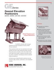
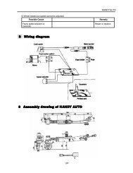
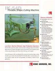
Selecting Headstock/Tailstock Positioners<br />
How to Select a Headstock/Tailstock To Best Meet Your<br />
Needs:<br />
Head and tail units are rated for overhanging loads. Determine<br />
the weight and how far ahead of the table the CG (Centerof-Gravity)<br />
of the work-piece will be located, then select the<br />
proper model from the chart on page 21.<br />
When head and tail units are used together, the load weight<br />
is shared by both units. As explained below, the weight is imposed<br />
on the flexible point of the clamping fixtures. The distance<br />
that the flexible point is ahead of the table determines the overhanging<br />
load on the head and tail units. This load can be compared<br />
to the chart on page 21, using the CG rating that corresponds<br />
to the flexible point’s distance away from the table.<br />
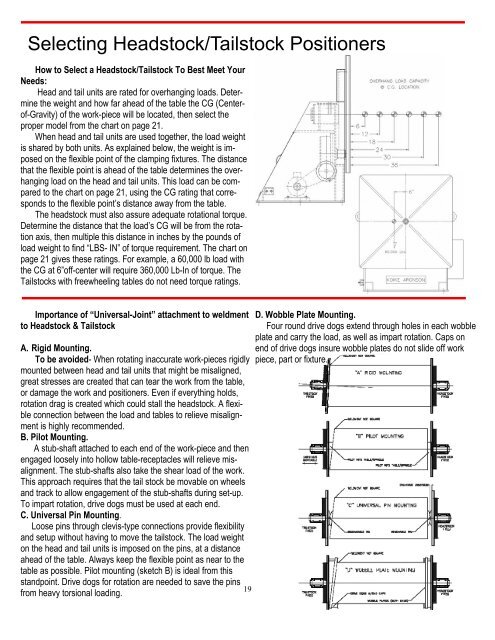
The headstock must also assure adequate rotational torque.<br />
Determine the distance that the load’s CG will be from the rotation<br />
axis, then multiple this distance in inches by the pounds of<br />
load weight to find “LBS- IN” of torque requirement. The chart on<br />
page 21 gives these ratings. For example, a 60,000 lb load with<br />
the CG at 6”off-center will require 360,000 Lb-In of torque. The<br />
Tailstocks with freewheeling tables do not need torque ratings.<br />
Importance of “Universal-Joint” attachment to weldment<br />
to Headstock & Tailstock<br />
A. Rigid Mounting.<br />
To be avoided- When rotating inaccurate work-pieces rigidly<br />
mounted between head and tail units that might be misaligned,<br />
great stresses are created that can tear the work from the table,<br />
or damage the work and positioners. Even if everything holds,<br />
rotation drag is created which could stall the headstock. A flexible<br />
connection between the load and tables to relieve misalignment<br />
is highly recommended.<br />
B. Pilot Mounting.<br />
A stub-shaft attached to each end of the work-piece and then<br />
engaged loosely into hollow table-receptacles will relieve misalignment.<br />
The stub-shafts also take the shear load of the work.<br />
This approach requires that the tail stock be movable on wheels<br />
and track to allow engagement of the stub-shafts during set-up.<br />
To impart rotation, drive dogs must be used at each end.<br />
C. Universal Pin Mounting.<br />
Loose pins through clevis-type connections provide flexibility<br />
and setup without having to move the tailstock. The load weight<br />
on the head and tail units is imposed on the pins, at a distance<br />
ahead of the table. Always keep the flexible point as near to the<br />
table as possible. Pilot mounting (sketch B) is ideal from this<br />
standpoint. Drive dogs for rotation are needed to save the pins<br />
19<br />
from heavy torsional loading.<br />
D. Wobble Plate Mounting.<br />
Four round drive dogs extend through holes in each wobble<br />
plate and carry the load, as well as impart rotation. Caps on<br />
end of drive dogs insure wobble plates do not slide off work<br />
piece, part or fixture.