Positioneering Workbook - Koike
Positioneering Workbook - Koike
Positioneering Workbook - Koike

You also want an ePaper? Increase the reach of your titles
YUMPU automatically turns print PDFs into web optimized ePapers that Google loves.
Universal Balance Positioner<br />
(1) First find the Center of Gravity of Rotation<br />
When a work-piece is placed on the worktable of an Aronson<br />
Positioner with its center of gravity located on the worktable rotational<br />
axis, it will be balanced on that axis. It will, therefore, be very<br />
easy to rotate on that axis, even if it is ten times heavier than the<br />
operator. In fact, it rotates so easily that a friction band had to be<br />
fitted to the worktable of the Positioner to provide a drag effect and<br />
to enable the operator to place and stop the work-piece wherever<br />
he wants. It is very easy to find the center of gravity of two dimensions,<br />
but all work-pieces have three dimensions, and all weldments<br />
require movement in two opposing axes, to obtain all possible positions.<br />
(2) Balance is achieved by adjusting the worm gear so that the<br />
tilt axis intersects and the center of gravity located on the rotation<br />
axis.<br />
The Worktable is at one end of the Arm and a worm and worm<br />
gear segment are at the other end. The Arm and the Gear Box are<br />
integral. A Shaft at the extreme end of the gear box rotates in Tapered<br />
Roller Bearings, in a barrel shaped housing. A simple adjustment<br />
of the worm by the operator will change the angle of the arm,<br />
allowing the tilt axis of the arm to intersect the center of gravity of<br />
the work-piece in the third dimension. With both axes intersecting<br />
the center of gravity of the work-piece, it can be pushed or pulled by<br />
your hand and simply put wherever you want it. . . effortlessly. . .<br />
because it is in balance. This is the principle of the <strong>Koike</strong> Aronson<br />
Universal Balance Positioner.<br />
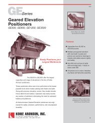
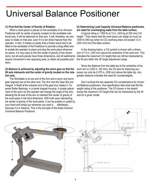
(3) Determining Load Capacity Universal Balance positioners<br />
are rated for overhanging loads from the table surface.<br />
A typical rating is “1000 lb at 12 in. (453 kg at 300 mm) CG<br />
height.” That means that the work-piece can weigh as much as<br />
1000 lb (453 kg) when its CG overhang does not exceed 12 in.<br />
(300 mm) from the table surface.<br />
In the drawing below, a CG symbol is shown with a dimension<br />
of 13 in. (330 mm) above the centerline of the work arm. This<br />
indicates the maximum CG height that can still be intersected by<br />
the tilt axis within the 30°angle adjustment range.<br />
Since the distance from the table top to the centerline of the<br />
work arm is 3.625 in. (92 mm), the CG axis for balancing purposes<br />
can only be 9.375 in. (238 mm) above the table top. Any<br />
greater distance indicates the need for counterweights.<br />
Don’t confuse the two separate CG considerations for Universal<br />
Balance positioners. One specification tells what load fits the<br />
weight rating of the positioner. The CG shown in the sketch<br />
shows the maximum CG height that can be intersected by the tilt<br />
axis for a given model.<br />
8