VISY-X - FAFNIR Gmbh
VISY-X - FAFNIR Gmbh
VISY-X - FAFNIR Gmbh

You also want an ePaper? Increase the reach of your titles
YUMPU automatically turns print PDFs into web optimized ePapers that Google loves.
Technical Documentation<br />
<strong>VISY</strong>-X<br />
VPI<br />
Edition: 07/2011<br />
Version: 1<br />
Article no.: 350068<br />
<strong>FAFNIR</strong> GmbH � Bahrenfelder Str. 19 � 22765 Hamburg � Germany � Tel.: +49 / 40 / 39 82 07–0 � Fax: +49 / 40 / 390 63 39
Table of contents<br />
1 Introduction....................................................................................3<br />
1.1 In this manual….................................................................................................4<br />
1.2 Requirements for service engineers.....................................................................4<br />
1.3 Safety instructions ..............................................................................................5<br />
2 Design and operation....................................................................6<br />
3 Installation .....................................................................................7<br />
3.1 Installation .........................................................................................................7<br />
3.2 Connection of the sensors..................................................................................7<br />
3.3 Interface connection RS-485...............................................................................8<br />
3.3.1 Programming interface.......................................................................................9<br />
3.3.2 Configuration of the VPI address ........................................................................9<br />
3.4 Connection of the supply voltage .......................................................................9<br />
3.5 Status LEDs ......................................................................................................10<br />
4 Technical data...............................................................................11<br />
4.1 VPI ...................................................................................................................11<br />
4.2 VPI--Supply ......................................................................................................12<br />
5 List of figures ...............................................................................13<br />
6 List of tables.................................................................................13<br />
7 Annex ...........................................................................................14<br />
7.1 Operating instructions VPI transducer ...............................................................14<br />
7.2 EC-type examination certificate - VPI ................................................................17<br />
© Copyright:<br />
Reproduction and translation is only permitted with the written consent of <strong>FAFNIR</strong>.<br />
<strong>FAFNIR</strong> reserves the right to carry out product alterations without prior notice.<br />
Page 2/19 VPI
1 Introduction<br />
The <strong>VISY</strong>-X system (Volume Information SYstem) provides highly precise and continuous<br />
filling level measurements for all commercially available fuels. With the VPI Interface (<strong>VISY</strong><br />
Power Interface), a filling level measurement can be taken in up to 256 tanks using a<br />
maximum of 32 VPIs. The product temperature and water level are measured simultaneously<br />
and the density can also be measured as an option.<br />
The system includes:<br />
� the VPI as a communication interface between the sensors and a higher-level<br />
system (host)<br />
� the <strong>FAFNIR</strong> VPI power supply (Art. no. 908315). As an option, an independent<br />
power supply can also be used, see chapter 3.4<br />
� the <strong>VISY</strong>-Stick and/or <strong>VISY</strong>-Reed sensors<br />
� as an option, the VIMS sensors from our system partner SGB (see chapter 1.1)<br />
can also be connected<br />
The sensors are connected with the VPI which is mounted inside the petrol station building.<br />
The VPI is a communication interface between the sensors and a higher-level system<br />
(host). Commands from the higher-level system to the sensors are allocated to the corresponding<br />
sensor terminals of the VPI. The feedback from the sensors is transmitted back<br />
to the higher-level system (host).<br />
The VPI supports the following protocols:<br />
– <strong>FAFNIR</strong> Universal Device Protocol (UDP)<br />
– H-Protocol<br />
In order to take advantage of all functions offered by the <strong>VISY</strong>-X system,<br />
the <strong>FAFNIR</strong> Universal Device Protocol must be used.<br />
VPI Page 3/19
1.1 In this manual…<br />
… you will be guided through the installation and set-up of the VPI interface.<br />
These instructions contain a description of all the steps needed to perform the installation.<br />
Please also observe the additional instructions in the following documents:<br />
� Technical Documentation <strong>VISY</strong>-Stick <strong>VISY</strong>-Reed (English) – Art. No. 207194<br />
� Technical Documentation <strong>FAFNIR</strong> UDP (English) – Art. no. 350052<br />
For the installation of the VIMS sensors, please also contact:<br />
� SGB GmbH, Hofstraße 10, 57076 Siegen, Germany<br />
Tel.: +49 271 48964-0, Fax: +49 271 48964-6, e-mail: sgb@sgb.de<br />
1.2 Requirements for service engineers<br />
The complete <strong>VISY</strong>-X system should only be installed by trained service engineers.<br />
Page 4/19 VPI
1.3 Safety instructions<br />
The <strong>VISY</strong>-X system is optimised for use in petrol stations and is compatible with all commercially<br />
available fuels. It serves as measuring and analysing the filling levels in the tanks.<br />
The system must be used exclusively for this purpose. Please observe and follow all product<br />
safety notes and operating instructions. The manufacturer accepts no liability for any<br />
loss or damage arising from improper use.<br />
The VPI interface has been developed, manufactured and tested in accordance with the<br />
latest good engineering practices and generally accepted safety standards. Nevertheless,<br />
hazards may arise from their use.<br />
The following safety precautions must be observed in order to reduce the risk of injury,<br />
electric shocks, fire or damage to the equipment:<br />
� Please do not make any changes to the system.<br />
� The installation, operation and maintenance must only be carried out by expert<br />
personnel.<br />
� Operators, installers and service technicians must comply with all applicable<br />
safety regulations. This also applies for local safety regulations and accident prevention<br />
guidelines, which are not included within these operating instructions.<br />
� During the installation process, valid national construction regulations must be<br />
observed.<br />
� The VPI must not be installed in potentially-explosive areas.<br />
� The VPI must be in a clean and undamaged condition at all times.<br />
� The VPI must only be powered by the permissible auxiliary power supply.<br />
The safety instructions in this manual are labelled as follows:<br />
Failure to observe these safety instructions runs the risk of potential<br />
accidents and damage to the <strong>VISY</strong>-X system.<br />
Useful tips and information in this manual to be observed are written in<br />
italics and identified by this symbol.<br />
VPI Page 5/19
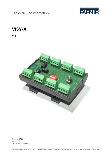
2 Design and operation<br />
The VPI is designed for the DIN mounting rail.<br />
It has eight intrinsically safe sensor terminals. At each individual sensor terminal of the VPI,<br />
it is possible to connect up to three different types of <strong>FAFNIR</strong> sensors (e.g. one <strong>VISY</strong>-Stick,<br />
one <strong>VISY</strong>-Stick Interstitial and one <strong>VISY</strong>-Stick Sump). These three types of sensors can be<br />
directly connected to each other at the measuring point. This means that only one cable<br />
(4-wire) is required for connection to the VPI interface.<br />
In combination with the VIMS sensors from our system partner for leakage<br />
control (SGB GmbH, Siegen), two <strong>FAFNIR</strong> sensors and two SGB sensors can<br />
be connected to the VPI using one single cable (4-wire).<br />
Connecting multiple sensors of the same type (e.g. 3 x <strong>VISY</strong>-Stick) to one<br />
sensor terminal is not permitted.<br />
The sensors are electrically supplied with power by the VPI. A 12 V direct current is necessary<br />
for the power supply of the VPI. The <strong>FAFNIR</strong> VPI-Supply (accessories) is safely galvanically<br />
isolated between the input and output and can supply up to two VPIs.<br />
Alternatively, another power supply can be used. Therefore, a power consumption of<br />
125 mA should be set for every VPI. The tolerance of the supply voltage must not exceed<br />
5 %.<br />
Depending on the number of sensors to be connected, up to 32 VPIs may be interconnected.<br />
Every VPI must hereby be assigned with its own address from 0 to 31 via a DIP<br />
switch.<br />
Page 6/19 VPI
3 Installation<br />
For the installation and operation of the interface VPI in Germany,<br />
the requirements of the Ordinance on Explosion Protection (ExVo),<br />
the Ordinance on Industrial Health and Safety (BetrSichV) and the<br />
equipment safety legislation must be observed (in other countries,<br />
equivalent local requirements and regulations must be observed). In<br />
all countries, valid and generally accepted good engineering practices<br />
as well as these operating instructions must be observed.<br />
All applicable local safety regulations and accident prevention<br />
guidelines not included in these operating instructions must also be<br />
observed.<br />
All wiring operations must be carried out with the power disconnected.<br />
3.1 Installation<br />
The VPI must be firmly connected inside a building to a mounting<br />
rail in a casing with a protection class of at least IP20.<br />
In casing with the corresponding protection class (at least IP54), the VPI is<br />
also suitable for outdoor installation.<br />
3.2 Connection of the sensors<br />
Connect the sensors to the sensor terminal clamps of the VPI (see Figure 1).<br />
The connection cable of the sensors must have the following properties:<br />
� 4-wire, unshielded cable, oil-resistant<br />
� Line cross section (4 x 0.5 mm² up to 250 m or 4 x 1.0 mm² over 250 m)<br />
� All blue or with blue markings (cable for intrinsically safe electric circuits)<br />
The maximum external inductance including the cable must not exceed<br />
5 mH and the maximum capacitance must not exceed 610 nF<br />
(see data sheet of the used cable).<br />
VPI Page 7/19
Figure 1: VPI terminals<br />
3.3 Interface connection RS-485<br />
In order to connect to the higher-level system (host), the VPI has a RS-485 interface with<br />
a 4-pole header plug on the underside of the board. The interface does not have its own<br />
power supply and must be supplied with 5V via the accompanying 4-pole connection<br />
cable.<br />
Two transmission speeds are supported:<br />
Baud rate Data bit Stop bit Parity<br />
1200 8 1 none<br />
4800 8 1 none<br />
Page 8/19 VPI
3.3.1 Programming interface<br />
Concealed at the back of the printed circuit board is a programming interface through<br />
which an update of the VPI firmware can be carried out if necessary. For more information,<br />
please contact <strong>FAFNIR</strong>.<br />
3.3.2 Configuration of the VPI address<br />
Up to 32 VPIs can be interconnected for the connection of the sensors. Every VPI must be<br />
assigned with its own address from 0 to 31. The addresses are configured by the sum of<br />
powers of 2 with the DIP switch S1.<br />
DIP switch S1<br />
VPI address<br />
1<br />
2 0 =1<br />
2<br />
2 1 =2<br />
VPI Page 9/19<br />
3<br />
2 2 =4<br />
4<br />
2 3 =8<br />
5<br />
2 4 =16<br />
0 OFF OFF OFF OFF OFF<br />
1 ON OFF OFF OFF OFF<br />
2 OFF ON OFF OFF OFF<br />
3 ON ON OFF OFF OFF<br />
4 OFF OFF ON OFF OFF<br />
…<br />
Table 1: DIP switch S1 for VPI address<br />
3.4 Connection of the supply voltage<br />
The supply with auxiliary power (electrical connection) takes place via a 2-pole header<br />
plug on the underside of the VPI. The respective 2-pole connection cable is included<br />
within the scope of supply.<br />
A 12 V direct current is necessary for the power supply of the VPI. The <strong>FAFNIR</strong> VPI-Supply<br />
(art. no. 908315) is provided as an accessory. The VPI-Supply can supply up to two VPIs.<br />
A minimum distance of 50 mm (thread measure) should be ensured<br />
between the VPI and the VPI-Supply.<br />
Alternatively, another power supply can be used. Therefore, a power consumption of<br />
125 mA should be set for every VPI. The tolerance of the supply voltage must not exceed<br />
5 %.<br />
If the <strong>FAFNIR</strong> VPI-Supply is not used for the power supply of the VPI,<br />
it is imperative that the sensors and the VPI are correctly integrated<br />
into the potential equalisation (PA).
3.5 Status LEDs<br />
There are one green LED and two red LEDs on the VPI.<br />
The green LED which is marked with "power", signals that the power supply is active and<br />
the VPI is ready for operation.<br />
The red LED which is marked with "RS-485", signals incoming data from the higher-level<br />
system.<br />
The red LED which is marked with "sensor", signals feedback from the sensors.<br />
Page 10/19 VPI
4 Technical data<br />
4.1 VPI<br />
The terminals are numbered with the figures 1 ... 8 and the additions +, A, B and - .<br />
The intrinsically safe sensor circuits are safely galvanically isolated from the auxiliary power<br />
circuit for the use of a VPI-Supply up to a peak of 375 V of the nominal voltage.<br />
The intrinsically safe sensor circuits are safely galvanically isolated from the control circuit<br />
up to a peak of 190 V of the nominal voltage.<br />
Explosion protection II (1) G [Ex ia Ga] IIC<br />
EC type approval certificate TÜV 10 ATEX 388544 X<br />
Permissible ambient temperature: -20 °C to +60 °C<br />
Auxiliary power<br />
(Terminals located at the rear)<br />
Sensor circuits<br />
(Terminals + A B -)<br />
Direct current<br />
12 V ± 5 %; approx. 125 mA, Um = 375 V<br />
Intrinsic safety ignition protection class [Ex ia Ga] IIC<br />
(linear output characteristic)<br />
Maximum values U 0 = 10.5 V<br />
I 0 = 41.0 mA<br />
P 0 = 99.8 mW<br />
Explosion protection group IIC IIB<br />
Permitted external inductance L 0 � 5 mH � 2 mH � 20 mH � 10 mH<br />
Permitted external capacity C 0 � 610 nF � 780 nF � 2.5 μF � 3 μF<br />
Measurement and control circuits<br />
(Plug connector S1)<br />
Table 2: Technical data VPI<br />
Interface circuit UN = 5 V<br />
Maximum safe voltage Um = 190 V<br />
VPI Page 11/19
4.2 VPI--Supply<br />
Two VPIs can be connected to one VPI-Supply unit.<br />
Explosion protection II (1) G [Ex ia Ga] IIC<br />
EC type approval certificate TÜV 10 ATEX 388544 X<br />
Permissible ambient temperature: -20 °C to +60 °C<br />
Power supply<br />
(Terminals L, N, PE)<br />
Alternating voltage 40 … 60 Hz<br />
230 V ±10 %; approx. 4 VA, Um = 253 V<br />
115 V ±10 %; approx. 4 VA, Um = 130 V<br />
24 V ±10 %; approx. 4 VA, Um = 30 V<br />
Output voltage 12 V DC, ±5 %, 250 mA<br />
Table 3: Technical data VPI-Supply<br />
Page 12/19 VPI
5 List of figures<br />
Figure 1: VPI terminals.....................................................................................................8<br />
6 List of tables<br />
Table 1: DIP switch S1 for VPI address .............................................................................9<br />
Table 2: Technical data VPI............................................................................................11<br />
Table 3: Technical data VPI-Supply.................................................................................12<br />
VPI Page 13/19
7 Annex<br />
7.1 Operating instructions VPI transducer<br />
Edition: 11.2010<br />
I Range<br />
The corresponding equipment for the VPI and VPI-Supply may only be used outside the potentially<br />
explosive area.<br />
The voltage supply for the VPI-Supply serves as powering the VPI transducer. The purpose of the VPI<br />
transducer is preferably to supply the electronic filling level sensors with power and transmit the<br />
measurement data to a higher-level analysis system.<br />
II Standards<br />
See EC type examination certificate.<br />
III Instructions for safe ...<br />
III.a ... use<br />
The corresponding VPI equipment has eight intrinsically safe sensor inputs. Each sensor is connected<br />
using four terminal clamps. Two clamps are provided for the intrinsically safe power supply whilst the<br />
other two are for the transmission of measurement data. At the same time, the VPI transducer is<br />
used to safely isolate intrinsically safe and non-intrinsically safe circuits. All sensor connections are<br />
galvanically connected to one another.<br />
The intrinsically safe sensor circuits of the VPI transducer are safely galvanically isolated from the auxiliary<br />
power supply circuit up to a peak of 375 V of the nominal voltage.<br />
The non-intrinsically safe control-circuit (RS-485 interface) is linked to a 4-pole connector plug. This<br />
connector establishes the connection to a higher-level data processing system. The intrinsically safe<br />
sensor circuits of the VPI transducer are galvanically isolated from this measuring and control circuit<br />
up to a peak of 190 V of the nominal voltage.<br />
III.b ... Installation<br />
All wiring operations must be carried out with the power disconnected. The specific EN directives and<br />
local installation regulations including EN 60079-14 must be observed. The wiring from the sensor to<br />
the control unit shall be carried out using a four-wire cable (preferably blue). The terminals +, -<br />
A and B on the sensor must be connected to the same terminals on the transducer.<br />
If the VPI-Supply is not used to power the VPI transducer, it is imperative that the sensors and the<br />
transducers are integrated correctly into the potential equalisation (PA). The PA terminal is located in<br />
the middle of the VPI printed circuit board. All sensors must be securely connected with the PA terminal<br />
of the VPI transducer. The specific construction regulations must be observed.<br />
III.c ... Assembly<br />
The VPI transducer and the VPI-Supply must be installed in a case with a protection class of at least<br />
IP20. It is important to ensure that non-intrinsically safe wiring connections are located with a clearance<br />
of at least 50 mm (thread measure) from the VPI printed circuit board and the intrinsically safe<br />
sensor terminals. This can also be achieved using suitable separation plates for example.<br />
III.d ... Commissioning<br />
Before commissioning, all devices must be checked to determine that they are correctly connected<br />
and working properly. The power supply, including that of downstream devices, must also be<br />
checked.<br />
Page 14/19 VPI
III.e ... Maintenance, servicing and repair<br />
The device is maintenance-free. In case of a defect, please send the transducer back to the manufacturer.<br />
Special conditions<br />
1 If the VPI-Supply is not being used, the sensors and the PA terminal on the VPI printed circuit<br />
board must be securely integrated with one another in the potential equalisation (PA).<br />
2 The VPI transducer and the VPI-Supply must be constructed in a case which has a protection class<br />
of at least IP20.<br />
3 When installing the VPI and the VPI-Supply, a clearance distance of at least 50 mm (thread measure)<br />
should be ensured between the two.<br />
4 The VPI transducer and the VPI-Supply are designed for use in ambient temperatures of -<br />
20 °C … +60 °C .<br />
IV Labelling<br />
VPI--Supply<br />
VPI<br />
1 Manufacturer: <strong>FAFNIR</strong> GmbH, Hamburg<br />
2 Type designation:<br />
3 Serial Number:<br />
VPI-Supply<br />
4 Certificate Number: TÜV 10 ATEX 388544 X<br />
5 CE marking: 0044<br />
1 Manufacturer: <strong>FAFNIR</strong> GmbH, Hamburg<br />
2 Type designation:<br />
3 Serial Number:<br />
VPI<br />
4 Certificate Number: TÜV 10 ATEX 388544 X<br />
5 Ex marking: II (1) G [Ex ia Ga] IIC<br />
6 CE marking: 0044<br />
7 Electrical Data: See operational manual for electrical data.<br />
VPI Page 15/19
V Electrical Data<br />
VPI-Supply<br />
The auxiliary power supply of the VPI-Supply is connected to the terminals PE, N and L. Depending<br />
on the design of this module, the auxiliary power supply is<br />
U = 24 V AC, 115 V AC, or 230 V AC, ± 10 %, 40 … 60 Hz, ~4 VA.<br />
The safe maximum voltage is<br />
U = m 30 V at 24 V AC, resp.<br />
U = m 130 V at 115 V AC, resp.<br />
U = m 253 V at 230 V AC, resp.<br />
The output voltage is 12 V DC, ±5 %<br />
Two VPI transducers can be connected to one VPI-Supply.<br />
VPI<br />
The auxiliary power supply for the VPI transducer is connected to a plug underneath the module<br />
and equals:<br />
U = 12 V DC, ±10 %, < 2 W.<br />
The safe maximum voltage is<br />
U = 253 V.<br />
m<br />
The sensor circuits are designed in the ignition protection "intrinsic safety" class [ia] with a linear<br />
output characteristic. The output values are:<br />
Uo � 10.5 V<br />
Io � 41.0 mA<br />
Po � 99.8 mW<br />
IIC IIB<br />
Permitted external inductance L o � 5 mH � 2 mH � 20 mH � 10 mH<br />
Permitted external capacity C o � 610 nF � 780 nF � 2.5 μF � 3 μF<br />
The terminals are numbered with the figures 1 ... 8 and the additions +, A, B and - .<br />
The intrinsically safe sensor circuits are safely galvanically isolated from the auxiliary power supply<br />
circuit up to a peak of 375 V of the nominal voltage.<br />
The intrinsically safe sensor circuits are safely galvanically isolated from the control circuit up to a<br />
peak of 190 V of the nominal voltage.<br />
Page 16/19 VPI
7.2 EC-type examination certificate - VPI<br />
VPI Page 17/19
Page 18/19 VPI
VPI Page 19/19