Lecture 3: Chapter 2, Part 1 - Classes
Lecture 3: Chapter 2, Part 1 - Classes
Lecture 3: Chapter 2, Part 1 - Classes

Create successful ePaper yourself
Turn your PDF publications into a flip-book with our unique Google optimized e-Paper software.
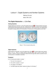
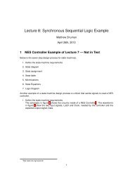
<strong>Lecture</strong> 3: <strong>Chapter</strong> 2, <strong>Part</strong> 1<br />
Matthew Shuman<br />
January 11th, 2011<br />
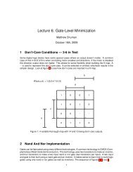
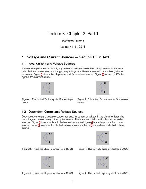
1 Voltage and Current Sources — Section 1.6 in Text<br />
1.1 Ideal Current and Voltage Sources<br />
An ideal voltage source will supply any current to achieve the desired voltage across its two terminals.<br />
An ideal current source will supply any voltage to achieve the desired current through its two<br />
terminals. Figure 1 shows the LTspice symbol for a voltage source. Figure 2 shows the LTspice<br />
symbol for a current source.<br />
Figure 1: This is the LTspice symbol for a voltage<br />
source<br />
Figure 2: This is the LTspice symbol for a current<br />
source<br />
1.2 Dependent Current and Voltage Sources<br />
Dependent current and voltage sources use another current or voltage in the circuit to determine<br />
the voltage or current being output by the source. There are four total combinations of dependent<br />
sources. Figure 3 is a current controlled current source and figure 4 is a voltage controlled current<br />
source. Figure 5 is a current controlled voltage source and figure 6 is a voltage controlled voltage<br />
source.<br />
Figure 3: This is the LTspice symbol for a CCCS<br />
Figure 4: This is the LTspice symbol for a VCCS<br />
Figure 5: This is the LTspice symbol for a CCVS<br />
Figure 6: This is the LTspice symbol for a VCVS<br />
1
2 Electrical Resistance, Ohm’s Law — Section 2.2 in Text<br />
Figure 7 shows the LTspice symbol for a resistor. A resistor is a device that is engineered to resist<br />
the flow of current. The dimensions are controlled according to the following equations. They are<br />
usually made out of carbon, which specifies the value of ρ.<br />
R = ρ ∗ L<br />
(1)<br />
A<br />
The relationship of voltage across and current through a resistor is stated in Ohm’s Law, which is<br />
the following equation.<br />
V = I ∗ R (2)<br />
Figure 7: This is the LTspice symbol for a resistor<br />
3 Nodes, Branches, and Loops — Section 2.3 in Text<br />
Figure 8 is the demonstration circuit using in lecture. There is a single 1.2 volt NiCd battery in the<br />
battery holder. The resistor is 3.3 kΩ. Figure 9 shows a LTspice schematic of this circuit.<br />
Figure 8: This is a photo of a circuit, built using a<br />
breadboard<br />
Figure 9: This is a schematic in LTspice<br />
Figure 10 shows how LTspice can simulate a circuit to solve for voltages and currents.<br />
ENGR 201
Figure 10: This is a simulation output in LTSpice<br />
4 Modeling a Bipolar Juntion Trasistor using a current dependent<br />
current source<br />
Figure 11 shows how a current dependent current source can be modeled in LTSpice. Figure 12<br />
shows the simulated output of the circuit in figure 11.<br />
ENGR 201
Figure 11: This is a schematic and netlist of a current dependent current source<br />
Figure 12: This is a schematic and netlist of a current dependent current source<br />
ENGR 201