MSSP-1000 - Derrickinternational Equipment Company
MSSP-1000 - Derrickinternational Equipment Company
MSSP-1000 - Derrickinternational Equipment Company

Create successful ePaper yourself
Turn your PDF publications into a flip-book with our unique Google optimized e-Paper software.
PROCESS FLOW<br />
<strong>MSSP</strong>-<strong>1000</strong><br />
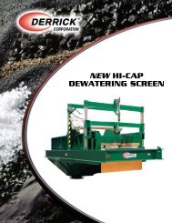
Flow from the TBM passes through a flowmeter and then to a Derrick C-56 low-speed, high-amplitude<br />
screening machine. The machine’s weir-style feeder distributes the slurry evenly on its urethane screen panels.<br />
Oversized material that does not pass through the screen bed is directed to a conveyor and stacker for<br />
deposit in a holding area. Solids and fluid that pass through the screen are directed by gravity to Sump 1 of<br />
the base tank, which is located directly below the screening machine.<br />
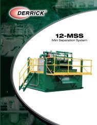
One abrasion-resistant pump draws slurry from the bottom of Sump 1 to feed 4 12” sand separator-type<br />
hydrocyclones. Each hydrocyclone discharges oversized material onto the urethane screening panels of<br />
a Derrick FLC-2000 screening machine. Undersize material and overflow fluid passing out the top of the<br />
hydrocyclones is discharged into Sump 2. Oversized material from each of the FLC-2000s is discharged<br />
to the belt conveyor. Fluid and solids that pass through the screens flow by gravity to Sump 2 for further<br />
processing.<br />
Two additional abrasion-resistant pumps have the capacity of drawing slurry from either the bottom of Sump<br />
1 to feed 8 additional 12” hydrocyclones or from Sump 2 to feed 80 4” hydrocyclones. Oversized material<br />
discharged from either the 12” sand separators or 4” hydrocyclones is further dried on 4 FLC-2000 screening<br />
machines. Overflow from the top of the hydrocyclones is fed by gravity to the appropriate sump.<br />
The three sumps in the base tank are separated by weirs for safe, gravity-flow operation. When the TBM is<br />
operating at 100 percent capacity, fluid passes through the processing equipment and then to the base tank<br />
sumps in sequential order. When the level in Sump 3 rises to the weir outlet, cleaned fluid flows by gravity to<br />
the TBM working tank. If the TBM pump is delivering less than 100 percent of design flow, part of the slurry<br />
in Sump 2 flows over the weir into Sump 1 instead of flowing out to the TBM tank. In addition, part of the<br />
slurry in Sump 3 returns to Sump 2 instead of flowing out to the TBM tank. This feature maintains sufficient<br />
fluid supply to the hydrocyclone feed pumps at all times.<br />
The plant includes two Derrick DE-7200 decanter-type centrifuges, which receive slurry from either the active<br />
working system or waste mud tank. Oversized material from the centrifuges is directed to the conveyor, while<br />
cleaned fluid flows by gravity to the TBM tank or to a site discharge point. When a nearly clear effluent<br />
discharge is desired, a completely automated dry polymer metering and mixing system can supply flocculent<br />
to both DE-7200 centrifuges simultaneously.<br />
Derrick <strong>Equipment</strong> <strong>Company</strong> – Modular Slurry Separation Plant<br />
3