3. Combination Meter System - Subaru Outback Forums
3. Combination Meter System - Subaru Outback Forums
3. Combination Meter System - Subaru Outback Forums

You also want an ePaper? Increase the reach of your titles
YUMPU automatically turns print PDFs into web optimized ePapers that Google loves.
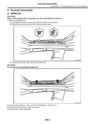
<strong>Combination</strong> <strong>Meter</strong> <strong>System</strong><br />
INSTRUMENTATION/DRIVER INFO<br />
<strong>3.</strong> <strong>Combination</strong> <strong>Meter</strong> <strong>System</strong><br />
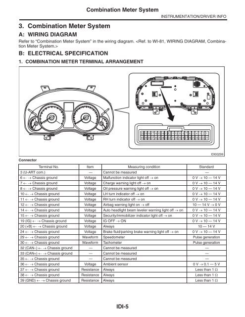
A: WIRING DIAGRAM<br />
Refer to “<strong>Combination</strong> <strong>Meter</strong> <strong>System</strong>” in the wiring diagram. <br />
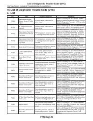
B: ELECTRICAL SPECIFICATION<br />
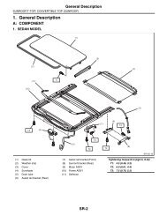
1. COMBINATION METER TERMINAL ARRANGEMENT<br />
20 19 18 17 16 15 14 13 12 11 10 9 8 7 6 5 4 3 2 1<br />
40 39 38 37 36 35 34 33 32 31 30 29 28 27 26 25 24 23 22 21<br />
IDI00299<br />
Connector<br />
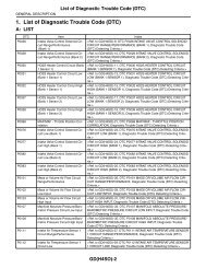
Terminal No. Item Measuring condition Standard<br />
3 (U-ART com.) — Cannot be measured —<br />
6 Chassis ground Voltage Malfunction indicator light off on 0 V 10 — 14 V<br />
7 Chassis ground Voltage Charge warning light off on 0 V 10 — 14 V<br />
8 Chassis ground Voltage Oil pressure warning light off on 0 V 10 — 14 V<br />
10 Chassis ground Voltage LH turn indicator off on 0 V 10 — 14 V<br />
11 Chassis ground Voltage RH turn indicator off on 0 V 10 — 14 V<br />
12 Chassis ground Voltage Airbag warning light on off 10 — 14 V 0 V<br />
14 Chassis ground Voltage Auto headlight beam leveler warning light off on 0 V 10 — 14 V<br />
15 Chassis ground Voltage Security/immobilizer indicator light off on 0 V 10 — 14 V<br />
19 (IG) Chassis ground Voltage IG OFF ON 0 V 10 — 14 V<br />
20 (+B) Chassis ground Voltage Always 10 — 14 V<br />
24 Chassis ground Voltage Brake fluid/parking brake warning light off on 0 V 10 — 14 V<br />
29 Chassis ground Waveform Speedometer Pulse generation<br />
30 Chassis ground Waveform Tachometer Pulse generation<br />
32 (CAN–) Chassis ground — Cannot be measured —<br />
33 (CAN+) Chassis ground — Cannot be measured —<br />
35 Chassis ground — Cannot be measured —<br />
36 Chassis ground Voltage Ambient sensor 0 V 0.1 — 5 V<br />
37 Chassis ground Resistance Always Less than 1 <br />
38 Chassis ground Resistance Always Less than 1 <br />
39 (GND) Chassis ground Resistance Always Less than 1 <br />
IDI-5
INSTRUMENTATION/DRIVER INFO<br />
C: OPERATION<br />
<strong>Combination</strong> <strong>Meter</strong> <strong>System</strong><br />
1. SELF-DIAGNOSIS DISPLAY MODE<br />
The self-diagnosis (checking of each meter, warning light, indicator light, illumination, LCD) of combination<br />
meter can be performed in the following procedure.<br />
CAUTION:<br />
Perform the steps described in 1) through 4) within 10 seconds.<br />
1) Within 3 seconds after turning the ignition switch to ON, set the lighting switch to tail light or headlight position.<br />
2) Press the trip meter knob three times.<br />
3) Turn the lighting switch to OFF, and press the trip meter knob three times.<br />
4) Set the lighting switch to tail light or headlight position again, and press the trip meter knob three times.<br />
NOTE:<br />
• When pressing the trip meter knob four times, the display changes to DTC display mode. <br />
• When pressing the trip meter knob five times, the display changes to dealer customize mode. <br />
• When the self-diagnosis function operates, the warning light, indicator light, and LCD display checks are<br />
performed. After this, the buzzer will sound for 0.5 seconds every time the trip meter knob is pressed, and operation<br />
checks are performed in the order of meter indicator needle operation, meter indicator needle indication,<br />
and LCD. Turn the ignition switch to OFF to cancel the self-diagnosis function.<br />
• When the engine starts during diagnosis, the self-diagnosis function is not cancelled, however, once the<br />
vehicle starts driving, the self-diagnosis function is deactivated automatically.<br />
5) Move on to the “<strong>Meter</strong> Indicator Needle Operation Check”.<br />
Check meter operation, warning light, indicator light, illumination and LCD.<br />
MIN indication<br />
<br />
MAX indication<br />
MAX indication<br />
<br />
MIN indication<br />
<strong>Meter</strong> indicator needle LCD display, illumination Warning lights, indicator lights<br />
6) Press the trip meter knob once.<br />
7) Move on to the “<strong>Meter</strong> Indicator Needle Indication Check”.<br />
Check meter operation, warning light, indicator light, and LCD.<br />
NOTE:<br />
• The meter indicator needle will switch every 1.5 seconds.<br />
• The ILL illumination level will be at the brightness it was set to when switching to the “<strong>Meter</strong> Indicator Needle<br />
Indication Check”.<br />
• During operation, “_S_2” is displayed on the LCD trip display.<br />
Speedometer<br />
(km/h)<br />
Tachometer<br />
(rpm)<br />
8) Press the trip meter knob once.<br />
ILL1 (Min. brightness)<br />
(Display for one second for each level)<br />
ILL6 (Max. brightness)<br />
ILL6 (Max. brightness)<br />
(Display for one second for each level)<br />
ILL1 (Min. brightness)<br />
Fuel gauge ECO gauge Low fuel warning<br />
light<br />
Light ON<br />
The engine coolant temperature warning<br />
light illuminates in red.<br />
Warning lights, indicator<br />
lights<br />
0 0 Lowest point Lowest point Light ON Light OFF<br />
0 0 E –Max Light ON<br />
The engine coolant<br />
temperature indicator<br />
light illuminates<br />
40 1000 1/2 0 Light OFF<br />
100 4000 F +Max Light OFF<br />
in blue.<br />
40 1000 1/2 0 Light OFF<br />
0 0 E –Max Light ON<br />
IDI-6
<strong>Combination</strong> <strong>Meter</strong> <strong>System</strong><br />
INSTRUMENTATION/DRIVER INFO<br />
9) Move on to the “LCD Display Check”.<br />
Check the LCD display.<br />
NOTE:<br />
• All warning lights and indicator lights turn off.<br />
• The meter indicator needle maintains its position in the “<strong>Meter</strong> Indicator Needle Indication Check”.<br />
• The ILL illumination level is lit at ILL6 (highest brightness).<br />
• After No. 14 is displayed in the illumination order, display is repeated from No. 1 again.<br />
ORDER<br />
1<br />
2<br />
AT/SS<br />
CRUISE/SET<br />
CRUISE<br />
OFF<br />
SET<br />
TRIP/ UNIT/ODO/<br />
S/I/S#<br />
A B<br />
888.8<br />
888888<br />
[ S] [ I] S#<br />
111.1<br />
111111<br />
DOOR/<br />
REAR GATE/<br />
TRUNK OPEN<br />
OFF<br />
3<br />
4<br />
CRUISE<br />
OFF<br />
A<br />
222.2<br />
222222<br />
[ S]<br />
33<strong>3.</strong>3<br />
333333<br />
OFF<br />
5<br />
6<br />
OFF<br />
SET<br />
B<br />
444.4<br />
444444<br />
[] I<br />
555.5<br />
555555<br />
OFF<br />
7<br />
8<br />
CRUISE<br />
OFF<br />
A<br />
666.6<br />
666666<br />
S#<br />
777.7<br />
777777<br />
OFF<br />
9<br />
10<br />
OFF<br />
SET<br />
B<br />
888.8<br />
888888<br />
[ S]<br />
999.9<br />
999999<br />
OFF<br />
11<br />
12<br />
CRUISE<br />
OFF<br />
A<br />
000.0<br />
000000<br />
[] I<br />
888.8<br />
888888<br />
OFF<br />
13<br />
14<br />
OFF<br />
SET<br />
B<br />
888.8<br />
888888<br />
S#<br />
888.8<br />
888888<br />
OFF<br />
IDI00316<br />
IDI-7
INSTRUMENTATION/DRIVER INFO<br />
<strong>Combination</strong> <strong>Meter</strong> <strong>System</strong><br />
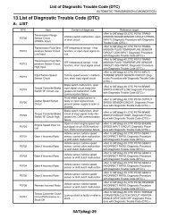
2. DTC DISPLAY MODE<br />
The combination meter DTC can be displayed according to the following procedure.<br />
CAUTION:<br />
Perform the steps described in 1) through 4) within 10 seconds.<br />
1) Within 3 seconds after turning the ignition switch to ON, set the lighting switch to tail light or headlight position.<br />
2) Press the trip meter knob four times.<br />
3) Turn the lighting switch to OFF, and press the trip meter knob four times.<br />
4) Set the lighting switch to tail light or headlight position again, and press the trip meter knob four times.<br />
5) Move on to the “DTC display mode”.<br />
NOTE:<br />
• If a diagnostic trouble code (DTC) is detected, an input error to meters exists. Check the harness on the<br />
body side and related parts.<br />
• Detected diagnostic trouble code (DTC) cannot be cleared.<br />
• When the engine starts during diagnosis, the self-diagnosis function is not cancelled, however, once ignition<br />
switch is turned OFF or the vehicle is driven, the DTC display mode is cancelled automatically.<br />
(1) When the DTC display mode operates, the LCD displays whether diagnostic trouble code (DTC) exists.<br />
DTC display Item Condition<br />
“--” - Normal<br />
“Er” - <strong>System</strong> error (meter error)<br />
B900 Power supply system When IG OFF is detected while driving<br />
B901 Speedometer Abnormal speed pulse value and CAN data value with engine ON<br />
B902<br />
Inconsistency between speed pulse value and CAN data value with<br />
Speedometer<br />
engine ON<br />
U116 Tachometer Abnormal input data with engine ON<br />
U140 Fuel meter Abnormal input data with engine ON<br />
U155 CAN communication CAN communication error<br />
U167 Immobilizer collation Collation with body integrated unit failed<br />
U422 Fuel meter Abnormal input data with IG ON<br />
U431 Fuel meter When input data out of range is detected with engine ON<br />
(2) If the diagnostic trouble code (DTC) is stored, ODO value at occurrence of trouble is displayed.<br />
NOTE:<br />
• Diagnostic trouble code (DTC) is stored for up to four cases. If diagnostic trouble code (DTC) is input exceeding<br />
four cases, the code is deleted in order starting with the oldest one.<br />
• When there are more than one diagnostic trouble code (DTC), the code is displayed according to the following<br />
conditions and switches every time when the trip meter knob is pressed.<br />
1. Displayed in the descending order of ODO value.<br />
IDI-8
<strong>Combination</strong> <strong>Meter</strong> <strong>System</strong><br />
INSTRUMENTATION/DRIVER INFO<br />
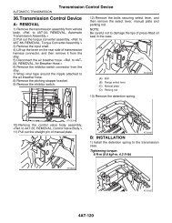
2. If the ODO value is the same, displayed in the ascending order of diagnostic trouble code (DTC) value.<br />
DTC reading completed<br />
One DTC Two DTCs Three DTCs Four DTCs<br />
Short Short Short<br />
Short<br />
No DTC (normal)<br />
Short<br />
Short<br />
Short<br />
<strong>System</strong> error<br />
Short<br />
Short<br />
Short : A short press (less than 0.8 sec.) on TRIP SW detected<br />
DTC display mode deactivated<br />
IDI00309<br />
<strong>3.</strong> DEALER CUSTOMIZE MODE<br />
The combination meter can be customized with dealer customize according to the following procedure.<br />
CAUTION:<br />
Perform the steps described in 1) through 4) within 10 seconds.<br />
1) Within 3 seconds after turning the ignition switch to ON, set the lighting switch to tail light or headlight position.<br />
2) Press the trip meter knob five times.<br />
3) Turn the lighting switch to OFF, and press the trip meter knob five times.<br />
4) Set the lighting switch to tail light or headlight position again, and press the trip meter knob five times.<br />
5) Move on to the “DEALER CUSTOMIZE MODE”.<br />
• When the dealer customize mode operates, the LCD displays each adjustment screen.<br />
• The dealer customize mode consists of three setting screens. {Avg.F/E Correction Screen}, {Ambient<br />
Temp. Correction Screen} and {Clock Adjust. Screen} is displayed cyclically in this order every time the trip<br />
meter knob is tapped.<br />
• Holding down the trip meter knob while each setting screen is displayed can change the setting value.<br />
NOTE:<br />
When ignition switch is turned OFF or the vehicle is driven, the customize mode is cancelled automatically.<br />
No. Customize mode Initial value Correction range<br />
1 Avg.F/E Correction Screen 0% 10%<br />
2 Ambient Temp. Correction Screen 0°C (°F) 3°C (°F)<br />
3 Clock Adjust. Screen on on or off<br />
IDI-9
INSTRUMENTATION/DRIVER INFO<br />
<strong>Combination</strong> <strong>Meter</strong> <strong>System</strong><br />
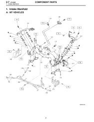
D: INSPECTION<br />
1. SYMPTOM CHART<br />
CAUTION:<br />
When measuring the voltage and resistance of each control module or sensor, use a tapered pin with<br />
a diameter of less than 0.64 mm (0.03 in) in order to avoid poor contact. Do not insert the pin more<br />
than 2 mm (0.08 in).<br />
Symptoms Repair order Note<br />
<strong>Combination</strong> meter assembly<br />
does not operate.<br />
Speedometer does not operate.<br />
Tachometer does not operate.<br />
Fuel gauge does not operate.<br />
ECO gauge does not operate.<br />
Warning buzzer for key left in ignition<br />
does not beep.<br />
1. Power supply<br />
2. Ground circuit<br />
<strong>3.</strong> <strong>Combination</strong> meter<br />
1. VDC C/M<br />
2. Harness<br />
<strong>3.</strong> <strong>Combination</strong> meter<br />
1. ECM<br />
2. Harness<br />
<strong>3.</strong> <strong>Combination</strong> meter<br />
1. Communication circuit<br />
2. Harness<br />
<strong>3.</strong> Body integrated unit<br />
4. Fuel level sensor<br />
5. <strong>Combination</strong> meter<br />
1. Communication circuit<br />
2. <strong>Combination</strong> meter<br />
1. Communication circuit<br />
2. <strong>Combination</strong> meter<br />
2. CHECK POWER SUPPLY AND GROUND CIRCUIT<br />
<br />
<br />
<br />
<br />
<br />
NOTE:<br />
The ECO gauge does not operate unless the vehicle is<br />
driven at least 1 km after the trip meter is reset.<br />
<br />
Step Check Yes No<br />
1 CHECK POWER SUPPLY FOR COMBINA-<br />
TION METER.<br />
1) Remove the combination meter.<br />
2) Measure the voltage between combination<br />
meter connector and chassis ground.<br />
Connector & terminal<br />
(i10) No. 20 (+) — Chassis ground (–):<br />
2 CHECK POWER SUPPLY FOR COMBINA-<br />
TION METER.<br />
1) Turn the ignition switch to ON.<br />
2) Measure the voltage between combination<br />
meter connector and chassis ground.<br />
Connector & terminal<br />
(i10) No. 19 (+) — Chassis ground (–):<br />
3 CHECK GROUND CIRCUIT OF COMBINA-<br />
TION METER.<br />
1) Turn the ignition switch to OFF.<br />
2) Measure the resistance between combination<br />
meter connector and chassis ground.<br />
Connector & terminal<br />
(i10) No. 39 — Chassis ground:<br />
Is the voltage 10 V or more? Go to step 2. Check the harness<br />
for open or short<br />
between the fuse<br />
and combination<br />
meter.<br />
Is the voltage 10 V or more? Go to step <strong>3.</strong> Check the harness<br />
for open or short<br />
between the ignition<br />
switch and<br />
combination meter.<br />
Is the resistance less than 10<br />
?<br />
Replace the meter<br />
case assembly.<br />
Repair or replace<br />
the harness.<br />
IDI-10
<strong>Combination</strong> <strong>Meter</strong> <strong>System</strong><br />
INSTRUMENTATION/DRIVER INFO<br />
<strong>3.</strong> CHECK VDC CONTROL MODULE<br />
Step Check Yes No<br />
1 CHECK VEHICLE SPEED SIGNAL.<br />
Is the voltage less than 1 V Replace the meter Go to step 2.<br />
1) Remove the combination meter mounting<br />
screws.<br />
2) Lift up the vehicle and support it with rigid<br />
racks.<br />
3) Drive the vehicle faster than 10 km/h (6<br />
MPH).<br />
WARNING:<br />
Be careful not to get caught in the running<br />
wheels.<br />
4) Measure the voltage between combination<br />
meter connector and chassis ground.<br />
Connector & terminal<br />
(i10) No. 29 (+) — Chassis ground (–):<br />
5 V or more?<br />
case assembly.<br />
2 CHECK HARNESS BETWEEN VDC CON-<br />
TROL MODULE AND COMBINATION<br />
METER.<br />
1) Turn the ignition switch to OFF.<br />
2) Disconnect the VDC control module connector<br />
and combination meter connector.<br />
3) Measure the resistance between the VDC<br />
control module connector and the combination<br />
meter connector.<br />
Connector & terminal<br />
(B310) No. 11 — (i10) No. 29:<br />
Is the resistance less than 10<br />
?<br />
Check the VDC<br />
control module.<br />
<br />
Repair or replace<br />
the harness.<br />
4. CHECK ENGINE CONTROL MODULE (ECM)<br />
Step Check Yes No<br />
Go to step 2.<br />
1 CHECK ECM SIGNAL.<br />
1) Start the engine.<br />
2) Measure the voltage between ECM connector<br />
and chassis ground.<br />
Connector & terminal<br />
(B135) No. 15 (+) — Chassis ground (–):<br />
Is the voltage 0 14 V or<br />
more?<br />
2 CHECK HARNESS BETWEEN COMBINA-<br />
TION METER AND ECM.<br />
1) Turn the ignition switch to OFF.<br />
2) Disconnect the ECM connector and combination<br />
meter connector.<br />
3) Measure the resistance between the ECM<br />
connector and the combination meter connector.<br />
Connector & terminal<br />
(B135) No. 15 — (i10) No. 30:<br />
Is the resistance less than 10<br />
?<br />
Replace the meter<br />
case assembly.<br />
Inspect the ECM.<br />
• H4 NA<br />
model:<br />
• H4 turbo<br />
model:<br />
• H6 model:<br />
Repair or replace<br />
the harness.<br />
IDI-11
INSTRUMENTATION/DRIVER INFO<br />
<strong>Combination</strong> <strong>Meter</strong> <strong>System</strong><br />
5. CHECK FUEL LEVEL SENSOR<br />
Step Check Yes No<br />
1 CHECK COMBINATION METER.<br />
1) Drain fuel.<br />
2) Check the fuel indication status in the combination<br />
meter.<br />
Does the fuel gauge needle<br />
indicate EMPTY and is the low<br />
fuel warning light blinking?<br />
Go to step 4. Go to step 2.<br />
2 CHECK COMBINATION METER.<br />
Perform the self-diagnosis of combination<br />
meter. <br />
3 CHECK DIAGNOSTIC TROUBLE CODE<br />
(DTC).<br />
1) Prepare the <strong>Subaru</strong> Select Monitor kit.<br />
2) Turn the ignition switch to ON (engine OFF)<br />
and run the “PC application for <strong>Subaru</strong> Select<br />
Monitor”.<br />
3) On «<strong>System</strong> Selection Menu» display,<br />
select {Integ. unit mode}.<br />
4) Select the {Diagnostic Code(s) Display}.<br />
4 CHECK HARNESS.<br />
1) Disconnect the connector of body integrated<br />
unit.<br />
2) Measure the resistance between body integrated<br />
unit connector and chassis ground.<br />
Connector & terminal<br />
(i84) No. 17 — Chassis ground:<br />
5 CHECK COMMUNICATION BETWEEN<br />
BODY INTEGRATED UNIT AND COMBINA-<br />
TION METERS.<br />
1) Remove the fuel sub level sensor.<br />
• H4 NA model:<br />
• H4 turbo model:<br />
• H6 model:<br />
2) Attach the approx. 100 resistance to the<br />
fuel sub level sensor connector terminal, and<br />
short circuit to the chassis ground.<br />
3) Turn the ignition switch to ON.<br />
Connector & terminal<br />
(R59) No. 1 — Chassis ground:<br />
6 CHECK BODY INTEGRATED UNIT.<br />
1) Retain the condition in step 5.<br />
2) Select the {Fuel level resistance} from the<br />
{Integ. unit mode} using the <strong>Subaru</strong> Select<br />
Monitor.<br />
Is operation normal? Go to step <strong>3.</strong> Replace the meter<br />
case assembly.<br />
<br />
Is a DTC detected?<br />
Perform the diagnosis<br />
according to<br />
DTC. <br />
Is the resistance 2 — 96 ? Go to step 5.<br />
Go to step 9.(If the<br />
step 1 is “Yes”)<br />
Does the meter needle indicate<br />
EMPTY?<br />
Is approx. 100 displayed in<br />
the data?<br />
Go to step 4.<br />
Repair or replace<br />
the harness.<br />
Go to step 7. Go to step 6.<br />
Go to step 11.<br />
Replace the body<br />
integrated unit.<br />
<br />
IDI-12
<strong>Combination</strong> <strong>Meter</strong> <strong>System</strong><br />
INSTRUMENTATION/DRIVER INFO<br />
Step Check Yes No<br />
Go to step 9. Go to step 8.<br />
7 CHECK COMMUNICATION BETWEEN<br />
BODY INTEGRATED UNIT AND COMBINA-<br />
TION METERS.<br />
1) Remove the fuel sub level sensor.<br />
• H4 NA model:<br />
• H4 turbo model:<br />
• H6 model:<br />
2) Attach the approx. 2 — 6 resistance to the<br />
fuel sub level sensor connector terminal, and<br />
short circuit to the chassis ground.<br />
3) Turn the ignition switch to ON.<br />
Connector & terminal<br />
(R59) No. 1 — Chassis ground:<br />
8 CHECK BODY INTEGRATED UNIT.<br />
1) Retain the condition in step 7.<br />
2) Select the {Fuel level resistance} from the<br />
{Integ. unit mode} using the <strong>Subaru</strong> Select<br />
Monitor.<br />
9 CHECK FUEL SUB LEVEL SENSOR.<br />
1) Remove the fuel sub level sensor.<br />
• H4 NA model:<br />
• H4 turbo model:<br />
• H6 model:<br />
2) Measure the resistance between the fuel<br />
sub level sensor connectors when the float is in<br />
FULL and EMPTY position.<br />
Connector & terminal<br />
(R59) No. 1 — No. 2:<br />
10 CHECK FUEL LEVEL SENSOR.<br />
1) Remove the fuel level sensor.<br />
• H4 NA model:<br />
• H4 turbo model:<br />
• H6 model:<br />
2) Measure the resistance between the fuel<br />
level sensor connectors when the float is in<br />
FULL and EMPTY position.<br />
Connector & terminal<br />
(R58) No. 1 — No. 4:<br />
11 CHECK COMBINATION METER OPERA-<br />
TION.<br />
1) Remove the combination meter.<br />
2) Attach the combination meter to another<br />
vehicle on which the fuel gauge operates normally<br />
to check its operation.<br />
Does the meter needle indicate<br />
FULL?<br />
Is the resistance 2 to 6 ? Go to step 11. Replace the body<br />
integrated unit.<br />
<br />
Is the resistance 1.0 to <strong>3.</strong>0 <br />
(FULL) and 61 to 63 <br />
(EMPTY)?<br />
Is the resistance 1.0 to <strong>3.</strong>0 <br />
(FULL) and 31 to 33 <br />
(EMPTY)?<br />
Is the fuel gauge normal?<br />
Go to step 10.<br />
Check the connection<br />
status of the<br />
harness and connector<br />
that may<br />
have a temporary<br />
poor contact.<br />
Replace the body<br />
integrated unit.<br />
<br />
Replace the fuel<br />
sub level sensor.<br />
Replace the fuel<br />
level sensor.<br />
Replace the meter<br />
case assembly.<br />
IDI-13
INSTRUMENTATION/DRIVER INFO<br />
<strong>Combination</strong> <strong>Meter</strong> <strong>System</strong><br />
6. CHECK ECO GAUGE<br />
Step Check Yes No<br />
Is a DTC of high-speed CAN<br />
Go to step 2.<br />
detected?<br />
1 CHECK DIAGNOSTIC TROUBLE CODE<br />
(DTC).<br />
1) Prepare the <strong>Subaru</strong> Select Monitor kit.<br />
2) Turn the ignition switch to ON (engine OFF)<br />
and run the “PC application for <strong>Subaru</strong> Select<br />
Monitor”.<br />
3) On «<strong>System</strong> Selection Menu» display,<br />
select {Integ. unit mode}.<br />
4) Select the {Diagnostic Code(s) Display}.<br />
2 CHECK ECO GAUGE.<br />
Perform the self-diagnosis of combination<br />
meter. <br />
Does ECO gauge operate<br />
properly?<br />
Perform the diagnosis<br />
according to<br />
DTC. <br />
Check the connection<br />
status of the<br />
harness and connector<br />
that may<br />
have a temporary<br />
poor contact.<br />
Replace the meter<br />
case assembly.<br />
<br />
7. CHECK WARNING BUZZER FOR KEY LEFT IN IGNITION.<br />
Step Check Yes No<br />
1 CHECK WARNING BUZZER FOR KEY LEFT Does the buzzer from the meter Normal operation. Go to step 2.<br />
IN IGNITION.<br />
sound?<br />
1) Insert the key into the ignition key lock.<br />
2) Open the driver’s side door.<br />
2 CHECK COMMUNICATION STATUS.<br />
1) Prepare the <strong>Subaru</strong> Select Monitor.<br />
2) On «<strong>System</strong> Selection Menu» display,<br />
select {Integ. unit mode}.<br />
3) Select the {key-lock warning SW} from {Current<br />
Data Display & Save}.<br />
4) Insert and remove the key.<br />
Does display switch between<br />
ON OFF?<br />
3 CHECK COMMUNICATION STATUS.<br />
1) Select the {Driver’s door SW input} from<br />
{Current Data Display & Save}.<br />
2) Open and close the door.<br />
4 CHECK COMMUNICATION STATUS.<br />
1) Turn the ignition switch to ON (engine OFF)<br />
and run the “PC application help for <strong>Subaru</strong><br />
Select Monitor”.<br />
2) On «<strong>System</strong> Selection Menu» display,<br />
select {Integ. unit mode}.<br />
3) Select the {Diagnostic Code(s) Display}.<br />
Does display switch between<br />
ON OFF?<br />
Is a DTC detected?<br />
Go to step <strong>3.</strong><br />
Go to step 4.<br />
Perform the diagnosis<br />
according to<br />
DTC. <br />
Check the ignition<br />
switch circuit.<br />
<br />
Check the door<br />
switch circuit.<br />
<br />
Go to step 5.<br />
5 CHECK COMBINATION METER.<br />
The self-diagnosis of combination meter is performed.<br />
<br />
Did the buzzer sound? Go to step 6. Replace the meter<br />
case assembly.<br />
6 CHECK COMBINATION METER.<br />
1) Remove the combination meter.<br />
2) Install the combination meter to another<br />
vehicle with a normally operating buzzer and<br />
check buzzer operation.<br />
Did the buzzer sound?<br />
Replace the body<br />
integrated unit.<br />
<br />
Replace the meter<br />
case assembly.<br />
IDI-14
<strong>Combination</strong> <strong>Meter</strong> <strong>System</strong><br />
INSTRUMENTATION/DRIVER INFO<br />
E: NOTE<br />
For operation procedures of each component of the combination meter system, refer to the respective section.<br />
• <strong>Combination</strong> meter:<br />
• Speedometer:<br />
• Tachometer:<br />
• Fuel gauge:<br />
• ECO gauge:<br />
IDI-15