Manual PT-Serie - Sunways AG
Manual PT-Serie - Sunways AG
Manual PT-Serie - Sunways AG

Create successful ePaper yourself
Turn your PDF publications into a flip-book with our unique Google optimized e-Paper software.
Indoor / Outdoor<br />
User <strong>Manual</strong><br />
<strong>Sunways</strong> Solar Inverter<br />
<strong>PT</strong> 30k, <strong>PT</strong> 33k<br />
english<br />
EN
<strong>Sunways</strong> <strong>AG</strong><br />
Photovoltaic Technology<br />
Macairestraße 3 - 5<br />
78467 Konstanz, Germany<br />
Phone: +49 (0)7531 996 77-0<br />
Fax: +49 (0)7531 996 77-444<br />
EMail: info@sunways.de<br />
Internet: www.sunways.de<br />
This user manual may only be reprinted or copied in whole or in part with the express, written approval of <strong>Sunways</strong><br />
<strong>AG</strong>. Any type of reproduction, distribution or storage on data carriers in any form and of any kind not authorised<br />
by <strong>Sunways</strong> <strong>AG</strong> represents a violation of the applicable copyright laws and will be prosecuted. We<br />
reserve the right to make technical changes which serve to improve the unit or increase the safety standard, without<br />
prior notice.<br />
Publisher responsible for the content: <strong>Sunways</strong> <strong>AG</strong><br />
This user manual contains products and product names which are registered trademarks. The mention of products<br />
and product names is used only for information purposes and does not represent product misuse. The passages<br />
referring to these products in this user manual do not represent original documentation of the respective<br />
product.
Introduction<br />
Introduction<br />
Thank you for choosing a <strong>Sunways</strong> Solar Inverter from <strong>PT</strong> series! You now have<br />
an innovative, high-quality product with unique features and consistently high<br />
efficiency.<br />
This Solar Inverter is equipped with HERIC ® topology and innovative <strong>PT</strong> circuitry<br />
and enables operation on a large number of solar modules – as accustomed<br />
from <strong>Sunways</strong> – without the use of a transformer.<br />
This user manual contains instructions for using the <strong>PT</strong> series. It will help you familiarise<br />
yourself with the functionality of the unit. Information is provided on<br />
safety, installation, commissioning, operation and system monitoring.<br />
Please follow the safety instructions carefully to enhance health and safety at<br />
the operating site of the unit.<br />
<strong>PT</strong> 30k to <strong>PT</strong> 33k 3
Introduction<br />
4 <strong>PT</strong> 30k to <strong>PT</strong> 33k
Introduction . . . . . . . . . . . . . . . . . . . . . . . . . . . . . . . . . . . . . . . . . . . . . . . . . . . 3<br />
1 Product description . . . . . . . . . . . . . . . . . . . . . . . . . . . . . . . . . . . . . . . . . . . . . 7<br />
1.1 Intended use. . . . . . . . . . . . . . . . . . . . . . . . . . . . . . . . . . . . . . . . . . . . . . . . . . . . . . . . 7<br />
1.2 Functional description . . . . . . . . . . . . . . . . . . . . . . . . . . . . . . . . . . . . . . . . . . . . . . . . 7<br />
1.3 Integration into solar system . . . . . . . . . . . . . . . . . . . . . . . . . . . . . . . . . . . . . . . . . . 8<br />
1.4 Module description . . . . . . . . . . . . . . . . . . . . . . . . . . . . . . . . . . . . . . . . . . . . . . . . . 10<br />
1.5 Delivery scope . . . . . . . . . . . . . . . . . . . . . . . . . . . . . . . . . . . . . . . . . . . . . . . . . . . . . 11<br />
2 Safety precautions . . . . . . . . . . . . . . . . . . . . . . . . . . . . . . . . . . . . . . . . . . . . 13<br />
2.1 General safety precautions . . . . . . . . . . . . . . . . . . . . . . . . . . . . . . . . . . . . . . . . . . . 13<br />
2.2 Explanation of symbols and warnings . . . . . . . . . . . . . . . . . . . . . . . . . . . . . . . . . . 14<br />
2.3 Basic safety measures . . . . . . . . . . . . . . . . . . . . . . . . . . . . . . . . . . . . . . . . . . . . . . . 15<br />
2.4 Safety concept . . . . . . . . . . . . . . . . . . . . . . . . . . . . . . . . . . . . . . . . . . . . . . . . . . . . . 15<br />
3 Technical data . . . . . . . . . . . . . . . . . . . . . . . . . . . . . . . . . . . . . . . . . . . . . . . . 17<br />
4 Installation . . . . . . . . . . . . . . . . . . . . . . . . . . . . . . . . . . . . . . . . . . . . . . . . . . . 19<br />
4.1 Mechanical installation . . . . . . . . . . . . . . . . . . . . . . . . . . . . . . . . . . . . . . . . . . . . . . 19<br />
4.2 Electrical installation . . . . . . . . . . . . . . . . . . . . . . . . . . . . . . . . . . . . . . . . . . . . . . . . 22<br />
4.3 Installing the communication equipment . . . . . . . . . . . . . . . . . . . . . . . . . . . . . . . 32<br />
5 Commissioning . . . . . . . . . . . . . . . . . . . . . . . . . . . . . . . . . . . . . . . . . . . . . . . 39<br />
5.1 Connecting and disconnecting the unit . . . . . . . . . . . . . . . . . . . . . . . . . . . . . . . . . 39<br />
5.2 Commissioning . . . . . . . . . . . . . . . . . . . . . . . . . . . . . . . . . . . . . . . . . . . . . . . . . . . . . 40<br />
6 Operation . . . . . . . . . . . . . . . . . . . . . . . . . . . . . . . . . . . . . . . . . . . . . . . . . . . 47<br />
6.1 General information . . . . . . . . . . . . . . . . . . . . . . . . . . . . . . . . . . . . . . . . . . . . . . . . 47<br />
6.2 System monitoring. . . . . . . . . . . . . . . . . . . . . . . . . . . . . . . . . . . . . . . . . . . . . . . . . . 62<br />
6.3 <strong>Sunways</strong> Browser . . . . . . . . . . . . . . . . . . . . . . . . . . . . . . . . . . . . . . . . . . . . . . . . . . . 72<br />
7 Maintenance. . . . . . . . . . . . . . . . . . . . . . . . . . . . . . . . . . . . . . . . . . . . . . . . . . 81<br />
7.1 Servicing schedule . . . . . . . . . . . . . . . . . . . . . . . . . . . . . . . . . . . . . . . . . . . . . . . . . . 81<br />
7.2 Maintenance interval. . . . . . . . . . . . . . . . . . . . . . . . . . . . . . . . . . . . . . . . . . . . . . . . 81<br />
7.3 Maintenance tasks . . . . . . . . . . . . . . . . . . . . . . . . . . . . . . . . . . . . . . . . . . . . . . . . . . 81<br />
A Appendix . . . . . . . . . . . . . . . . . . . . . . . . . . . . . . . . . . . . . . . . . . . . . . . . . . . . 83<br />
A.1 Installation methods and cable cross-sections . . . . . . . . . . . . . . . . . . . . . . . . . . . . 83<br />
A.2 General liability disclaimer . . . . . . . . . . . . . . . . . . . . . . . . . . . . . . . . . . . . . . . . . . . 84<br />
5
Product description<br />
1 Product description<br />
1.1 Intended use<br />
The Solar Inverter from <strong>PT</strong> series is the link between your solar generator and<br />
the public power grid. The energy from the connected solar generator is converted<br />
to grid-compliant AC current and fed into the grid.<br />
Solar modules which require earthing of the negative or positive terminal cannot<br />
be operated with the Solar Inverter <strong>PT</strong> 30k to <strong>PT</strong> 33k. If in doubt, always ask<br />
your module manufacturer about a release!<br />
1.2 Functional description<br />
Conversion from direct to alternating<br />
current<br />
Operating and display elements<br />
The Solar Inverter <strong>PT</strong> 30k to <strong>PT</strong> 33k converts the direct current produced by the<br />
solar generator into alternating current. The alternating current is then fed into<br />
the public power grid as a three-phase current.<br />
Various interfaces are available for system configuration and monitoring:<br />
<br />
Control panel (LCD display and keyboard) for displaying operating and status<br />
values or for inputting system parameters<br />
<br />
<br />
Operating LED<br />
Integrated web server for display and configuration via a web browser<br />
Interfaces Bus interface for connecting a <strong>Sunways</strong> modem, an analog modem, an ISDN<br />
modem or a GSM/GPRS modem<br />
<br />
<br />
<br />
<br />
<br />
<br />
<br />
Ethernet interface for connecting a PC or for integration in existing networks<br />
RS485 interface for communication with external data loggers<br />
CAN bus interface for interconnecting several Solar Inverter<br />
S0 pulse output for controlling large displays<br />
Activation of large display in web browser<br />
Alarm relay for realising simple monitoring locally<br />
Interface for connecting an irradiance and temperature sensor<br />
Data logging<br />
The Solar Inverter <strong>PT</strong> 30k to <strong>PT</strong> 33k offers internal data logging for recording<br />
and saving system data:<br />
<br />
<br />
<br />
5-minute mean values of voltages, currents, output, temperature and irradiance<br />
(if sensor is installed)<br />
5-minute, daily, monthly and annual energy yield values<br />
Memory for malfunction messages<br />
Grid monitoring<br />
The Solar Inverter <strong>PT</strong> 30k to <strong>PT</strong> 33k assumes the task of grid monitoring for the<br />
protection of the unit and persons. In case of abnormal grid conditions, feeding<br />
is immediately interrupted and the inverter disconnects from the grid by triggering<br />
the grid relay.<br />
<strong>PT</strong> 30k to <strong>PT</strong> 33k 7
Product description<br />
Design <strong>PT</strong> 30k to <strong>PT</strong> 33k<br />
The basic configuration is shown in the block diagram.<br />
The solar generator voltage connected to the inverter input is initially adapted<br />
by the DC actuator and then converted to alternating current by the high-efficiency<br />
HERIC ® inverter. The AC connection is made with 5 wires due to the 3-phase<br />
feed and passive grid monitoring.<br />
Network<br />
Control and monitoring<br />
Solar generator<br />
+ DC+<br />
=<br />
=<br />
L1<br />
L2<br />
L3<br />
–<br />
DC–<br />
=<br />
~<br />
PE<br />
DC actuator<br />
HERIC ® inverter<br />
N<br />
L1 L2 L3 PE N<br />
1.3 Integration into solar system<br />
Solar generator configuration<br />
The technical data of the selected solar generator must match the <strong>PT</strong> 30k to <strong>PT</strong><br />
33k specification (see Technical Data). Incorrect dimensioning can lead to reductions<br />
in the yield and to destruction of the unit.<br />
The Sundim design program from <strong>Sunways</strong> can be used for this purpose. <strong>Sunways</strong><br />
Sundim can be found on the enclosed CD-ROM or on our website at http:/<br />
/www.sunways.eu/de/.<br />
Be sure to take the following points into account before planning your system:<br />
<br />
<br />
<br />
<br />
<br />
Watch the celestial alignment of the modules. In Central Europe a maximum<br />
yield is achieved with a module tilt of 30 to the horizontal and direct south<br />
orientation of the solar generator<br />
field.<br />
The cell output decreases as the module temperature increases. Install your<br />
solar generator with sufficient ventilation at the rear.<br />
Check your solar generator approx. every three years for soiling. This occurs<br />
especially on the lower edge of the modules and forms a haze that cannot<br />
be washed off even by heavy rain. Yield reduction can be prevented by<br />
cleaning the modules with a wet cloth or a brush.<br />
Avoid shading of individual modules or solar cells in your system. This can<br />
lead to major reductions in yield.<br />
Please note the maintenance intervals of the inverter. See servicing schedule<br />
on enclosed product CD.<br />
8 <strong>PT</strong> 30k to <strong>PT</strong> 33k
Product description<br />
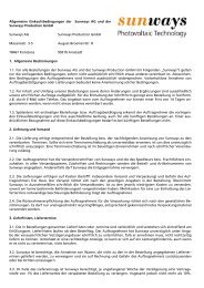
Standard components of a solar<br />
system<br />
Depending on the recommendations of your PV planning expert, your PV system<br />
consists of the following components:<br />
1<br />
5<br />
DC<br />
6<br />
7<br />
2<br />
3<br />
AC<br />
4<br />
1 Solar generator<br />
2 Generator connection box (string<br />
box)<br />
3 Solar Inverter with integrated DC<br />
load break switch<br />
4 Mains fuse, AFI type B and energy<br />
meter<br />
Options<br />
5 Irradiance sensor with integrated<br />
temperature sensor<br />
6 PC for monitoring system<br />
7 Large display<br />
<strong>PT</strong> 30k to <strong>PT</strong> 33k 9
Product description<br />
1.4 Module description<br />
600 478<br />
2<br />
1<br />
900<br />
2<br />
100<br />
3 4 5 6 7 8<br />
L3 L2 L1 N PE<br />
Diagram: IP 42 and IP 54 variants<br />
1 Control panel with LCD display,<br />
operating LED and console<br />
2 Fan guard + filter cartridge<br />
3 Communication interfaces<br />
4 AC connection<br />
5 AC overvoltage protection Cat. II<br />
6 DC overvoltage protection Cat. II<br />
(optional)<br />
7 DC load break switch<br />
8 DC connection<br />
10 <strong>PT</strong> 30k to <strong>PT</strong> 33k
Product description<br />
660<br />
600<br />
480<br />
1360<br />
670 540<br />
1 2 3 4 5 6 7 8 9<br />
Diagram: IP 55/Outdoor variant<br />
1 Mounting rail<br />
2 AC overvoltage protection<br />
3 AC connection L3, L2, L1<br />
4 AC connection N<br />
5 AC connection PE<br />
6 DC load break switch<br />
7 Solar generator Minus<br />
8 Solar generator Plus<br />
9 DC overvoltage protection Cat. II<br />
1.5 Delivery scope<br />
The delivery consists of:<br />
<br />
<br />
Solar Inverter of the <strong>PT</strong> series<br />
CAN terminating resistor connector (connected)<br />
Ethernet cable, 3 m (CAT 5e, 1:1)<br />
<br />
<br />
<br />
Control cabinet key<br />
Warranty card<br />
Installation Instructions - SETUP<br />
<strong>PT</strong> 30k to <strong>PT</strong> 33k 11
Product description<br />
<br />
CD-ROM, including <strong>Sunways</strong> Sundim design program, product and service information<br />
Checking delivery<br />
Before shipment our products are checked for proper condition. Despite careful,<br />
recyclable packing, transport damage may occur, for which the transport<br />
company is generally responsible.<br />
Please check the Solar Inverter thoroughly on delivery.<br />
Should you discover damage to the packing or the Solar Inverter, please inform<br />
the transport company immediately. Your specialist dealer will be happy to provide<br />
assistance if required. Any damage report must be received by the transport<br />
company in writing no later than seven days after receipt of the goods.<br />
Note regarding delivery<br />
A "shock watch" is located on the outer packaging and on the inside of the inverter.<br />
Removal of the shock indicator inside the unit is prohibited and immediately voids<br />
the guarantee!<br />
Diagram: Shock watch - left: not triggered! Right: triggered!<br />
If the shock watch has been triggered on delivery, please note this on the delivery<br />
documentation before you take the unit from the forwarding agent (example:<br />
"Shock watch was triggered on delivery") and report the triggered<br />
shock watch with identification number and Solar Inverter serial number immediately<br />
to the technical hotline.<br />
DANGER<br />
<br />
Never put the unit into operation as it could be functionally damaged.<br />
12 <strong>PT</strong> 30k to <strong>PT</strong> 33k
Safety precautions<br />
2 Safety precautions<br />
2.1 General safety precautions<br />
Follow the instructions in the<br />
operating manual.<br />
Safe handling and trouble-free operation of the <strong>PT</strong> 30k to <strong>PT</strong> 33k inverter requires<br />
knowledge of the basic safety precautions.<br />
This user manual contains the most important information for operating the<br />
system safely.<br />
Each person concerned with the installation, commissioning, maintenance and<br />
operation of the inverter must have read and understood the entire user manual<br />
and, in particular, the chapter entitled Safety Precautions.<br />
In addition, the rules and regulations for accident prevention applicable for the<br />
operating site/plant must be observed.<br />
Risks associated with handling<br />
the Solar Inverter <strong>PT</strong> 30k to <strong>PT</strong><br />
33k<br />
The Solar Inverter has been built in accordance with the state of the art and the<br />
recognised safety rules and may only be used<br />
<br />
for its intended purpose and<br />
<br />
in a safe condition.<br />
Improper use may lead to dangers to the life and limb of the user or others, or<br />
can adversely affect the system or other property.<br />
In case of malfunctions which can impair safety, the system must be shut down<br />
immediately and secured against being switched on again. The malfunction<br />
must then be eliminated immediately.<br />
Warranty and liability<br />
The <strong>Sunways</strong> General Terms and Conditions of Sale and Delivery always apply.<br />
Warranty and liability claims for personal injury or damage to property are excluded<br />
if they were caused by one or more of the following:<br />
<br />
<br />
<br />
<br />
<br />
<br />
<br />
<br />
<br />
<br />
<br />
Improper use of the inverter<br />
Improper installation, commissioning, operation and maintenance<br />
Operation of the inverter with defective and/or non-operational safety and<br />
protective equipment<br />
Failure to observe the information in the user manual regarding installation,<br />
commissioning, operation and maintenance<br />
Unauthorised modifications<br />
Inadequate monitoring of wearing parts<br />
Improper repairs<br />
Emergencies caused by external influence or force majeure<br />
Defective shock indicator<br />
Faulty operation over a time period of at least one week<br />
Operation in an unsuitable environment (see classification of air quality)<br />
<strong>PT</strong> 30k to <strong>PT</strong> 33k 13
Safety precautions<br />
2.2 Explanation of symbols and warnings<br />
The following warnings and symbols are used to help you quickly understand<br />
this manual and safely use the Solar Inverter.<br />
Warnings used in this user manual<br />
DANGER<br />
This symbol indicates an immediate danger which will result in death, injury or<br />
serious damage if the applicable safety regulations are not followed.<br />
DANGER<br />
Extreme danger from electric shock!<br />
This symbol indicates an immediate danger from electric shock which will result<br />
in death, injury or serious damage if the applicable safety regulations are not<br />
followed.<br />
CAUTION<br />
CAUTION<br />
This symbol indicates an immediate danger which can result in damage if the<br />
applicable safety regulations are not followed.<br />
Symbols used in this user manual<br />
NOTE<br />
Information<br />
This symbol indicates important information which contributes to a better understanding<br />
of the inverter.<br />
Warnings and symbols on unit<br />
The following warnings on the inverter housing indicate hazards. Always observe<br />
the warnings exactly.<br />
This symbol indicates that the user manual must be read and understood before<br />
putting the unit into operation.<br />
Hot surface! The housing can heat up during operation.<br />
Always disconnect the unit from the mains supply and the PV generator before<br />
opening the cover. The unit still carries life-threatening voltage for approx. five<br />
minutes internally and at the connection terminals of the PV generator following<br />
disconnection from the PV generator. The energy storage capacitors are<br />
not completely discharged until after this time. You must wait at least five minutes<br />
after disconnecting the unit from the mains supply and from the PV generator<br />
before opening the unit.<br />
14 <strong>PT</strong> 30k to <strong>PT</strong> 33k
Safety precautions<br />
Warning! High leakage current,<br />
earth connection essential before<br />
connecting supply.<br />
WARNING<br />
High leakage currents. Be sure to make an earthing connection before connecting<br />
the power supply circuit (AC system).<br />
2.3 Basic safety measures<br />
All electrical work on the Solar Inverter must be carried out by a qualified electrician<br />
while observing the VDE regulations, national and other regulations.<br />
The protective screen and rear wall may only be removed and maintenance may<br />
only be carried out by persons who are authorised by <strong>Sunways</strong>.<br />
When circuit breakers are tripped, the cause of the fault must be determined<br />
and eliminated before recommissioning the unit.<br />
Check electrical equipment regularly.<br />
Retighten any loose connections.<br />
Replace damaged lines/cables immediately.<br />
2.4 Safety concept<br />
The following parameters are monitored and displayed continuously and simultaneously<br />
by the inverter controller:<br />
<br />
<br />
<br />
<br />
<br />
<br />
DC overvoltage<br />
Overvoltage L1, L2, L3<br />
Undervoltage L1, L2, L3<br />
Stand-alone operation<br />
Overfrequency L1, L2, L3<br />
Underfrequency L1, L2, L3<br />
Surge error (brief overvoltage L1, L2, L3)<br />
<br />
<br />
<br />
<br />
DC share in AC current L1, L2, L3<br />
AFI residual current increase > 30 mA<br />
AFI residual current > 300 mA<br />
Overtemperature of heat sink, interior, chokes<br />
When a malfunction occurs, feeding is immediately interrupted and the Solar<br />
Inverter disconnects from the grid by triggering the mains contactor.<br />
The potential-free alarm relay switches (except for grid undervoltage L1).<br />
The following protective equipment is also provided:<br />
<strong>PT</strong> 30k to <strong>PT</strong> 33k 15
Safety precautions<br />
<br />
Grid-side varistors (class III)<br />
These protect the power semiconductors in case of high-energy, short-term<br />
voltage peaks in the grid and dissipate the energy in the choke in case of a<br />
grid disconnection.<br />
<br />
Grid-side overvoltage protection (class III)<br />
Protection against atmospheric overvoltages (e.g. caused by remote strikes<br />
during thunderstorms).<br />
<br />
Optional grid-side overvoltage protection (class II)<br />
Protection against atmospheric overvoltages (e.g. caused by remote strikes<br />
during thunderstorms).<br />
16 <strong>PT</strong> 30k to <strong>PT</strong> 33k
Technical data<br />
3 Technical data<br />
Model <strong>PT</strong> 30k <strong>PT</strong> 33k<br />
Article no.<br />
with/without DC overvoltage<br />
protection<br />
with/without DC overvoltage<br />
protection<br />
IP 42 (pre-configured for Germany) SI330P11B / SI330P21B SI333P11B / SI333P21B<br />
IP 54 (pre-configured for Germany) SI330P31B / SI330P41B SI333P31B / SI333P41B<br />
IP 55 / Outdoor (EU device) SI330P20B / SI330P40B SI333P20B / SI333P40B<br />
DC input<br />
Rated DC output 31000 W 34500 W<br />
Maximum DC current<br />
Nominal DC voltage<br />
75.0 A<br />
700 V<br />
MPP voltage range 420 V to 800 V 460 V to 800 V<br />
Maximum DC voltage<br />
1000 V<br />
DC connection 2 terminal blocks 16-35 mm (outdoor: 16-70 mm )<br />
Number of MPP trackers 1<br />
Overvoltage category<br />
Lightning protection level<br />
II (according to DIN VDE 0110 Part1)<br />
SPD Typ 2 (class 2, VDE 0185-305-4) in variant with DC-OVP<br />
AC output<br />
Rated AC output 30000 W 33333 W<br />
Maximum AC output 30000 W 33333 W<br />
Rated AC current 43.5 A per phase 48.3 A per phase<br />
Maximum AC current 50.0 A per phase 53.0 A per phase<br />
Nominal frequency<br />
Frequency range<br />
Grid voltage<br />
50 Hz<br />
47.5 - 51.5 Hz (according to DIN VDE 0126-1-1/A1)<br />
400 V<br />
AC voltage range -20% to +15% (according to DIN VDE 0126-1-1)<br />
Distortion factor < 4%<br />
Power factor (Cos Phi) 1 or configurable between -0.9 and +0.9<br />
Grid voltage monitoring Three-phase (according to DIN VDE 0126-1-1)<br />
Earth fault protection AFI (AC/DC sensitive) according to DIN VDE 0126-1-1<br />
Insulation, frequency and DC current monitoring<br />
Required phases for grid connection<br />
Integrated according to DIN VDE 0126-1-1<br />
3 (L1, L2, L3, N, PE)<br />
AC connection 5 terminal blocks 16 to 25 mm (IP 55/outdoor: 16 to 70 mm )<br />
AC overvoltage category<br />
III (according to DIN VDE 0110 Part1)<br />
Lightning protection level SPD Typ 2+3 (class 2+3, VDE 0185-305-4)<br />
<strong>PT</strong> 30k to <strong>PT</strong> 33k 17
Technical data<br />
Model <strong>PT</strong> 30k <strong>PT</strong> 33k<br />
Performance data<br />
Stand-by consumption<br />
Night-time consumption<br />
< 4 W<br />
< 0.1 W<br />
Maximum efficiency 98.0 % 98.0 %<br />
Max. European efficiency 97.6 % 97.6 %<br />
MPP efficiency (static) 99.9 % 99.9 %<br />
Circuit type<br />
HERIC ® topology, three-phase, transformerless<br />
Other features<br />
DC switch according to IEC 60947-1/3<br />
DC overvoltage protection<br />
Grid-connection fuse layout<br />
Data interfaces<br />
Sensor interfaces<br />
Display<br />
System monitoring<br />
Power supply unit protected on PCB<br />
Integrated<br />
Depending on variant<br />
3 x 63 A (16 mm ) / AFI type B<br />
Ethernet, CAN, potential-free signalling relay, S0, modem, RS485<br />
Irradiance, temperature<br />
LCD dot matrix, backlit, 128 x 64 pixels<br />
Automatic alarms via e-mail, <strong>Sunways</strong> browser, <strong>Sunways</strong> portal<br />
T2A/250 V<br />
IP rating according to IEC 60529 IP 42 / IP 54 (outdoor: IP 55)<br />
Max. relative humidity<br />
Air quality according to EN 60721-3-4<br />
95% / non-condensing<br />
for mechanical active substances: 3S1-IP 42, 3S2-IP55/Outdoor<br />
for chemical active substances: 4C1-IP42, 4C1-IP55/Outdoor<br />
Climate class 4K4H (in accordance with EN 60721--4)<br />
Maximum height above sea level<br />
Cooling<br />
Ambient temperature<br />
Stiffening plates on the sides<br />
Overload characteristics<br />
Dimensions (height x width x depth)<br />
Weight<br />
Installation type<br />
Noise level<br />
Standard warranty (option)<br />
1000 m<br />
Forced cooling by fan (fresh air supplied: approx. 350 m 3 / hour)<br />
-20C to 40°C (to 50°C with derating)<br />
for installations in direct sunligt (optionally available,<br />
Art.Nr.SE104M10A)<br />
Operating point offset<br />
100 x 60 x 48 cm (outdoor: 136 x 67 x 54 cm)<br />
approx. 155 kg (outdoor: approx. 170 kg)<br />
Standing installation<br />
Approx. 70 dBA (outdoor: approx. 76 dBA)<br />
5 years (with service contract: up to 20 years)<br />
Certificates CE, DIN VDE 0126-1-1/A1, RD 1663/2000, RD 661/2007, CEI 11-20<br />
v.1, Sezione F Guida Enel, BDEW Medium Voltage Directive and<br />
February 2011 addendum, TR 3 (REV. 21) and TR 8 (Rev. 4)<br />
18 <strong>PT</strong> 30k to <strong>PT</strong> 33k
Installation<br />
4 Installation<br />
4.1 Mechanical installation<br />
Requirements for installation<br />
location<br />
DANGER<br />
<br />
<br />
<br />
The Solar Inverter may not be installed in areas subject to explosion hazards.<br />
The Solar Inverter may not be exposed to corrosive gases.<br />
No combustible materials must be stored within 3 metres of the solar inverter.<br />
Protection against moisture<br />
and foreign bodies<br />
<br />
The <strong>PT</strong> 30k to <strong>PT</strong> 33k application range varies according to model.<br />
The IP 42 variant is suitable for indoor installation. The air quality must at<br />
least correspond to Class 3S1 for mechanically active substances as well as<br />
Class 4C1 for chemically active substances.<br />
The IP 54 variant can be used for the roofed outdoor area. The air quality<br />
must at least correspond to Class 3S2 for mechanically active substances as<br />
well as Class 4C1 for chemically active substances.<br />
The IP 55/Outdoor variant allows outdoor installation. If possible, use a<br />
roof-covered area protected from rain and dust as an installation location<br />
and avoid direct sunlight. The air quality must at least correspond to Class<br />
3S2 for mechanically active substances as well as Class 4C1 for chemically active<br />
substances.<br />
Stiffening plates on the sides optionally available.<br />
Classification of air quality for<br />
mechanically active substances<br />
(acc. to EN 60721-3-4)<br />
Environmental conditions for site-specific<br />
use<br />
Class<br />
3S1 3S2 3S3 3S4<br />
a) Sand in air [mg/m 3 ] - 30 300 3000<br />
b) Dust (suspended matter content) [mg/m 3 ] 0.01 0.2 0.4 4.0<br />
b) Dust (rainfall) [mg/m 3 ] 0.4 1.5 15 40<br />
Locations where the occurrence of dust is<br />
kept to a minimum through appropriate<br />
measures.<br />
Locations where no special measures for reducing<br />
the sand or dust occurrence have<br />
been taken and are not close to sand.<br />
x x x x<br />
x x x<br />
Locations close to sources of sand or dust. x x<br />
Locations in production facilities where there<br />
is no sand or dust, or locations in geographical<br />
regions where a higher proportion of<br />
sand and dust can occur in the air.<br />
x<br />
<strong>PT</strong> 30k to <strong>PT</strong> 33k 19
Installation<br />
Classification of air quality for<br />
chemically active substances<br />
(acc. to EN 60721-3-4)<br />
Environmental conditions for<br />
site-specific use<br />
Class<br />
4C1 4C2 4C3 4C4<br />
Limit Average Limit Average Limit Average Limit<br />
a) Sea salt Occurrence of salt spray<br />
b) Sulphur dioxide, mg/m3 0.1 0.3 1.0 5.0 10 13 40<br />
c) Hydrogen sulphide, mg/m3 0.01 0.1 0.5 3.0 10 14 70<br />
d) Chlorine, mg/m3 0.1 0.1 0.3 0.3 1.0 0.6 3.0<br />
e) Hydrogen chloride, mg/m3 0.1 0.1 0.5 1.0 5.0 1.0 5.0<br />
f) Hydrogen fluoride, 0.003 0.01 0.03 0.1 2.0 0.1 2.0<br />
g) Ammonia, mg/m3 0.03 1.0 3.0 10 35 35 175<br />
h) Ozone, mg/m3 0.01 0.05 0.1 0.1 0.3 0.2 2.0<br />
i) Nitrogen oxides, mg/m3 0.1 0.5 1.0 3.0 9.0 10 20<br />
Locations in rural or also<br />
densely populated regions<br />
with little industry or moderate<br />
traffic density.<br />
x x x x<br />
Locations in densely populated<br />
regions with industry and high<br />
traffic density.<br />
Locations in the immediate vicinity<br />
of industrial plants with<br />
chemical emissions.<br />
Locations inside industrial<br />
plants, emissions of dangerous<br />
chemical substances in high<br />
concentrations.<br />
x<br />
x<br />
x<br />
x<br />
x<br />
Mechanical load-bearing capacity<br />
<br />
Note during installation that the Solar Inverter weighs 155 kg or 170 kg (IP<br />
54/Outdoor variant). The installation surface must be firm and able to carry<br />
this weight in the long term. A concrete foundation is recommended.<br />
Thermal interaction The installation surface and the rear and side walls of the installation site<br />
must consist of flame-retardant material (not suitable: surface of wood or<br />
plastic; suitable: e.g. concrete), as the frame of the <strong>PT</strong> 30k to <strong>PT</strong> 33k can heat<br />
up to a maximum of 85C.<br />
<br />
A minimum distance of 1 m to other units, cabinets, ceilings, cable ducts, etc.<br />
must be maintained to the sides of the housing. A distance 0.3 m must be<br />
maintained from the rear wall of the <strong>PT</strong> 30k to <strong>PT</strong> 33k for service purposes<br />
(see diagram).<br />
20 <strong>PT</strong> 30k to <strong>PT</strong> 33k
Installation<br />
500<br />
1000<br />
1000<br />
500 0<br />
<br />
<br />
<br />
<br />
<br />
The Solar Inverter must be installed upright to enable adequate free convection.<br />
Solar Inverter may not be stacked in order to prevent excessive warming.<br />
If several <strong>PT</strong> Solar Inverter are operated in an enclosed space, adequate fresh<br />
air supply must be ensured. Larger systems should be configured in collaboration<br />
with <strong>Sunways</strong> at the design stage.<br />
The ambient temperature must be between -20 C and +40 C. At ambient<br />
temperatures above 40C, the Solar Inverter automatically regulates its output<br />
downwards.<br />
The IP 42 and IP 54 variants should not be exposed to direct sunlight to protect<br />
them from unnecessary external warming. The outdoor version is protected<br />
by a sun shade for operation in direct sunlight.<br />
Installation (IP 42, IP 54 variants)<br />
For Solar Inverter installation, proceed as follows:<br />
1. The Solar Inverter is attached to the pallet with retaining claws. Remove the<br />
retaining claws.<br />
2. Use a trolley for transporting the unit to the installation site.<br />
3. Use the retaining claws to secure the Solar Inverter on the installation surface.<br />
Do not subject inverters to extreme shocks, otherwise the internal shock indicator<br />
will be activated (>25 g acceleration) and the unit guarantee thus rendered<br />
void.<br />
<strong>PT</strong> 30k to <strong>PT</strong> 33k 21
Installation<br />
Installation (IP 55/Outdoor variant)<br />
Proceed as follows to install the <strong>PT</strong> 30k to <strong>PT</strong> 33k outdoors:<br />
1. The Solar Inverter is attached to the pallet with retaining claws. Remove the<br />
retaining claws.<br />
2. Use a forklift truck, a wheel loader or crane to transport the unit to the installation<br />
site.<br />
3. Secure the Solar Inverter on the installation surface (e.g. on a concrete base)<br />
with the screws included in the delivery contents. Use the pressed-on hole<br />
template in the cover for this.<br />
Do not subject inverters to extreme shocks, otherwise the internal shock indicator<br />
will be activated (>25 g acceleration) and the unit guarantee thus rendered<br />
void.<br />
4.2 Electrical installation<br />
Cable installation (IP 42, IP 54<br />
variants)<br />
DANGER<br />
Extreme danger from electric shock!<br />
<br />
<br />
Touching live parts can result in death.<br />
All electrical work must be carried out by a qualified electrician while observing<br />
the VDE regulations, national and other regulations.<br />
DANGER<br />
<br />
<br />
<br />
For units with cable entry terminals that are installed externally or in rooms<br />
where small rodents are to be expected (e.g. mice in factory buildings), the<br />
installation of rodent protection is obligatory. Otherwise the warranty becomes<br />
void.<br />
Even with installation of the rodent protection, a rodent infestation cannot<br />
be 100% excluded.<br />
Rodent protection is only included as standard in the IP54 variant. For the IP<br />
42 variant, it can, however, also be ordered and retrofitted separately (Art.<br />
No. SE103M10A).<br />
22 <strong>PT</strong> 30k to <strong>PT</strong> 33k
Installation<br />
1 2<br />
3 4 4 5<br />
Cable installation IP 42, IP 54<br />
1 Rodent protection (only included<br />
as standard in the IP54 variant)<br />
2 Bars with foam rubber<br />
3 Strain relief device<br />
4 Cable brackets<br />
5 Cable<br />
Proceed as follows with the cable installation for the IP 42 and IP 54 variants:<br />
1. Release the screws of the foam strips, push them apart and remove the front<br />
part of the foam strip.<br />
2. Remove the rodent protection. Note the mounting position!<br />
3. Only bend the punch-outs on the rodent protection, which are needed for<br />
the cable. To ensure the cable can optimally fitted, remove just the half of a<br />
punch-out where necessary.<br />
<strong>PT</strong> 30k to <strong>PT</strong> 33k 23
Installation<br />
DANGER<br />
Use a tool (e.g. pliers) to bend the punch-outs in order to avoid injury.<br />
NOTE<br />
The individual ribs of the rodent protection should be bent along the length of<br />
the cable and should not be broken!<br />
4. Configuration of the rodent protection:<br />
1<br />
2<br />
3<br />
1 Punch-outs for AC cables<br />
2 Punch-outs for interface cables<br />
3 Punch-outs for DC cables<br />
5. Guide the cable on the Solar Inverter back over the cable brackets through<br />
the opening of the unit in front of the rear foam strip.<br />
6. Open the strain relief device and guide the cables through it.<br />
7. Install the cables (see Solar generator connection and Grid connection).<br />
8. Pull the cables back slightly and re-attach them with the strain relief device.<br />
24 <strong>PT</strong> 30k to <strong>PT</strong> 33k
Installation<br />
9. Re-insert the rodent protection in the unit housing. Note the correct mounting<br />
position and ensure that the cables are routed exactly through the bent<br />
punch-outs.<br />
10.Replace the front part of the foam strip.<br />
11.Push the bars back together and secure them with the bolts.<br />
Cable installation (IP 55/Outdoor<br />
variant)<br />
DANGER<br />
Extreme danger from electric shock!<br />
<br />
<br />
Touching live parts can result in death.<br />
All electrical work must be carried out by a qualified electrician while observing<br />
the VDE regulations, national and other regulations.<br />
NOTE<br />
Correct cable installation<br />
<br />
<br />
<br />
The unit only meets all requirements of housing protection class IP 54/Outdoor<br />
if all cable entries have been screwed in properly.<br />
In the case of unused cable entries, the connection area must be closed with<br />
the blank plugs included.<br />
Unclosed openings in the connection box of the unit can lead to damage<br />
caused by moisture, dust or animals. This renders the guarantee void!<br />
<strong>PT</strong> 30k to <strong>PT</strong> 33k 25
Installation<br />
Fig. 1:<br />
IP 55/Outdoor illustration: Cable entry<br />
Solar generator connection<br />
DANGER<br />
Extreme danger from electric shock!<br />
<br />
<br />
<br />
<br />
<br />
<br />
<br />
<br />
<br />
<br />
<br />
<br />
Touching live parts can result in death.<br />
All electrical work must be carried out by a qualified electrician while observing<br />
the VDE regulations, national and other regulations.<br />
Execute the direct current wiring in accordance with the system dimensioning<br />
of your planning expert.<br />
Prepare all solar generator cables before connecting the solar generator to<br />
the Solar Inverter.<br />
Check each solar generator string for proper operation with an open-circuit<br />
voltage and short-circuit current measurement before connecting the string<br />
to the inverter.<br />
Check the rating plate on the Solar Inverter to ensure that it is approved for<br />
the maximum solar generator voltage.<br />
The positive and negative lines must be kept electrically separate from the<br />
earth potential.<br />
Touchable, live parts of the solar generator (e.g. metal frame, carrying structure,<br />
etc.) must be earthed (connection with PE).<br />
Check the solar generator for freedom from short-circuits to earth.<br />
Before connecting the solar generator to the Solar Inverter, open the integrated<br />
DC load break switch (position 0).<br />
After the solar generator is connected to the Solar Inverter and the DC load<br />
break switch is switched on, the direct generator voltage is present internally.<br />
Always disconnect the mains connection first by switching off the corresponding<br />
mains fuse and before disconnecting the solar generator side by opening<br />
the DC load break switch.<br />
26 <strong>PT</strong> 30k to <strong>PT</strong> 33k
Installation<br />
Overview<br />
The solar generator can be directly connected to the Solar Inverter with a string.<br />
Use the DC terminals that are accessible from inside for the connection.<br />
NOTE<br />
<br />
<br />
The solar generator strings running to the string box must be identically dimensioned<br />
and comply with the specifications of the Solar Inverter.<br />
No external DC load break switch is required. A DC load break switch as required<br />
in accordance with DIN VDE 0100-712 is integrated in the Solar Inverter.<br />
1<br />
– +<br />
L3 L2 L1 N PE<br />
2<br />
Diagram: IP 42, IP 54 variants<br />
1 DC load break switch 2 Solar generator connection<br />
Diagram: IP 55/Outdoor variant<br />
1 DC load break switch 2 Solar generator connection<br />
Installation<br />
DANGER<br />
Extreme danger from electric shock!<br />
<br />
<br />
<br />
Touching live parts can result in death.<br />
All electrical work must be carried out by a qualified electrician while observing<br />
the VDE regulations, national and other regulations.<br />
Ensure that the cables are installed securely.<br />
<strong>PT</strong> 30k to <strong>PT</strong> 33k 27
Installation<br />
NOTE<br />
<br />
<br />
<br />
Any kind of soiling (dust, moisture, etc.) has a negative effect on the terminals<br />
with regard to function over the intended period of use.<br />
DC connection cables with cross-sections between 16 mm and 35 mm or<br />
between 16 mm and 70 mm for (Outdoor) are permitted.<br />
The copper cables must be double-insulated and UV-resistant ("Radox"<br />
cables from Huber & Suhner, for example, are suitable).<br />
The following sequence must be observed during assembly:<br />
15/20<br />
1. Strip the voltage-free line.<br />
<br />
<br />
with end splice 15 mm<br />
without end splice 20 mm<br />
C<br />
B<br />
A<br />
2. Apply a screwdriver at a slant (A) to the locking device and push it in until<br />
it is vertical (B). The screwdriver then locks it in place (C).<br />
3. Introduce the stripped cable into the cable clamp and push the screwdriver<br />
forward into the original position.<br />
The following sequence must be observed during assembly:<br />
15/20<br />
1. Strip the voltage-free line.<br />
2. The IP 54/Outdoor variant has screw terminals. These are fully suited for<br />
copper cables from 16 mm to 70 mm . The screws to the terminal blocks<br />
must be tightened with a torque of 6-8 Nm. The use of aluminium cables is<br />
only possible for cross sections of 35 mm -70 mm . Please observe the specifications<br />
of the cable/cable socket manufacturer (removal of oxide layer,<br />
use of Vaseline or grease).<br />
CAUTION<br />
Please avoid squeezing the cable insulation or the end splice. Improper connection<br />
may damage the equipment!<br />
String box<br />
The string box enables connection of up to 8 or 12 solar generator strings to a<br />
DC bus line that can be connected directly to the Solar Inverter.<br />
The string box has protection rating IP65 and can therefore also be installed<br />
near the solar generator. The string box can be equipped with fuses or dummy<br />
sleeves. Pay attention to correct installation of metric cable glands and blind<br />
28 <strong>PT</strong> 30k to <strong>PT</strong> 33k
Installation<br />
caps as otherwise the watertightness of the IP65 is not guaranteed.<br />
String box options<br />
The <strong>Sunways</strong> string box is available with the following options:<br />
<br />
<br />
<br />
<br />
<br />
<br />
for up to 8 or up to 12 PV strings<br />
with/without DC overvoltage protection<br />
with/without DC load break switch<br />
fuses for different currents<br />
CAN string box incl. string monitoring<br />
Dummy sleeves<br />
Further information can be found in the Solar Inverter Accessories section at<br />
www.sunways.de.<br />
DANGER<br />
<br />
First disconnect the solar generator incl. string box with the aid of the DC<br />
load break switch of the inverter. Only then open the string fuses. Opening<br />
of the string fuse under live conditions can lead to life-threatening arcing!<br />
+<br />
–<br />
+ –<br />
12345678 12345678<br />
+<br />
–<br />
+<br />
–<br />
Mains connection<br />
DANGER<br />
Extreme danger from electric shock!<br />
<br />
<br />
Touching live parts can result in death.<br />
All electrical work must be carried out by a qualified electrician while observing<br />
the VDE regulations, national and other regulations.<br />
<strong>PT</strong> 30k to <strong>PT</strong> 33k 29
Installation<br />
<br />
<br />
<br />
Note the AC terminal assignment. An incorrect assignment can result in the<br />
unit being destroyed.<br />
No consumers may be connected to the supply line from the Solar Inverter to<br />
the mains fuse.<br />
Always disconnect the mains connection first by switching off the corresponding<br />
mains fuse and before disconnecting the solar generator side by opening<br />
the DC load break switch.<br />
NOTE<br />
If the voltage on the AC connection exceeds the permissible value due to a long<br />
line length or an insufficient cable cross-section, the Solar Inverter will be disconnected<br />
from the mains. In power grids with a low capacity and a high solar<br />
generator output, this can lead to individual Solar Inverter being switched off<br />
and then on again several times.<br />
Overview<br />
An AC terminal strip on the underside of the unit is used for the five-wire grid<br />
connection (L1, L2, L3, N, PE) of the solar inverter. Feeding is always three-phase<br />
via the AC terminal.<br />
2<br />
1<br />
L3 L2 L1 N PE<br />
Diagram: IP 42, IP 54 variants<br />
1 AC connection 2 DC load break switch<br />
Diagram: IP 55/Outdoor variant<br />
1 AC connection 2 DC load break switch<br />
The unit is centrally earthed using PE terminals. No separate earthing of the solar<br />
generator is required.<br />
30 <strong>PT</strong> 30k to <strong>PT</strong> 33k
Installation<br />
A corresponding circuit breaker is recommended as a line protection element in<br />
the grid feed direction:<br />
3 x 63 A with slow-blow characteristic C<br />
(for connection cross-sections ≥ 16 mm 2 )<br />
A three-pin circuit breaker or individual fuses can be used. Protection is implemented<br />
according to the installation method. A guide is provided in the appendix.<br />
An AFI type B must be installed at the mains.<br />
The AC power distribution incl. mains fuse should be placed as close as possible<br />
to the inverter.<br />
PE N L3 L2 L1<br />
Mains fuse<br />
AFI TYP B<br />
2<br />
3<br />
4<br />
1<br />
INVERTER<br />
NOTE<br />
<br />
<br />
A three-phase meter must be used.<br />
Some grid operators require the use of a reverse-current-capable meter.<br />
Installation<br />
DANGER<br />
Extreme danger from electric shock!<br />
<br />
<br />
<br />
<br />
Touching live parts can result in death.<br />
All electrical work must be carried out by a qualified electrician while observing<br />
the VDE regulations, national and other regulations.<br />
Note the AC terminal assignment. An incorrect assignment can result in the<br />
unit being destroyed.<br />
Ensure that the cables are installed securely.<br />
NOTE<br />
<br />
<br />
Any kind of soiling (dust, moisture, etc.) has a negative effect on the terminals<br />
with regard to function over the intended period of use.<br />
The following cross-sections are recommended as suitable AC connection<br />
cables for power lengths of up to 50 m.<br />
16 mm solid copper cable<br />
16 mm flexible copper/non-metallic sheathed cable<br />
<strong>PT</strong> 30k to <strong>PT</strong> 33k 31
Installation<br />
The following sequence must be observed during assembly:<br />
15/20<br />
1. Strip the voltage-free line.<br />
<br />
with end splice 15 mm<br />
<br />
without end splice 20 mm<br />
2. Introduce a screwdriver vertically into the locking device.<br />
3. Introduce the stripped cable into the cable clamp and pull the screwdriver<br />
out again.<br />
The following sequence must be observed during assembly:<br />
15/20<br />
1. Strip the voltage-free line.<br />
2. The IP 55/Outdoor variant has screw terminals. These are fully suited for copper<br />
cables from 16 mm to 70 mm . The screws to the terminal blocks must<br />
be tightened with a torque of 6-8 Nm. The use of aluminium cables is only<br />
possible for cross sections of 35 mm - 70 mm . Please observe the specifications<br />
of the cable/cable socket manufacturer (removal of oxide layer, use of<br />
Vaseline or grease).<br />
CAUTION<br />
Please avoid squeezing the cable insulation or the end splice. Improper connection<br />
may damage the equipment!<br />
4.3 Installing the communication equipment<br />
The communication interfaces are located above the AC terminals.<br />
32 <strong>PT</strong> 30k to <strong>PT</strong> 33k
Installation<br />
L3 L2 L1 N PE<br />
Diagram: IP 42, IP 54 variants<br />
Diagram: IP 55/Outdoor variant<br />
Interface overview<br />
2<br />
1 3 4 5 6 7<br />
RS485-<br />
RS485+<br />
1 Ethernet connection<br />
2 Modem connection<br />
3 CAN bus<br />
4 S0 interface (pulse output, e.g. for<br />
large display)<br />
5 Terminal for temperature and irradiance<br />
sensor<br />
6 RS485 for external data logger<br />
7 Connection for alarm relay<br />
All screw connections should be tightened<br />
with a max. of 0.5 Nm.<br />
Pin assignment<br />
Ethernet Modem CAN CAN<br />
8 7 6 5 4 3 2 1<br />
8 7 6 5 4 3 2 1<br />
8 7 6 5 4 3 2 1<br />
The connectors for the CAN interfaces and for the modem interface have the<br />
following pin assignment:<br />
CAN and modem<br />
<strong>PT</strong> 30k to <strong>PT</strong> 33k 33
Installation<br />
CAN<br />
Modem<br />
Pin Description Meaning Description Meaning<br />
1 N.C. >1 TXh<br />
2 CAN_GND 0 V / GND >2 TX1<br />
3 CAN_H Bus line (dominant<br />
high)<br />
Installation<br />
Up to 99 NT, <strong>PT</strong> and AT series units can be networked via a CAN bus. The following<br />
table shows the recommended cable cross-sections depending on bus<br />
length and number of nodes:<br />
Bus length/<br />
Number of nodes<br />
Bit rate 32 64 99<br />
100 m 500 kbit 0.25 mm or<br />
AWG 24<br />
250 m 250 kbit 0.34 mm or<br />
AWG 22<br />
500 m 125 kbit 0.75 mm or<br />
AWG 18<br />
0.25 mm or<br />
AWG 24<br />
0.5 mm or<br />
AWG 20<br />
0.75 mm or<br />
AWG 18<br />
0.25 mm or<br />
AWG 24<br />
0.5 mm or<br />
AWG 20<br />
1.0 mm or<br />
AWG 16<br />
If the values in the table cannot be maintained, the signal must be strengthened<br />
with the installation of a CAN bridge, with which the length of the CAN bus can<br />
be extended up to 500 m. Bus length, number of nodes and the cable cross-section<br />
thus influence the way in which a CAN bridge is used.<br />
Inverter<br />
XX<br />
CAN bridge<br />
Inverter<br />
XX<br />
Inverter<br />
XX<br />
CAN bus<br />
Network length / number of nodes / cable cross-section<br />
outside table values<br />
Use of one or several CAN bridges<br />
You can purchase the CAN bridge from <strong>Sunways</strong> - please contact the Technical<br />
Hotline.<br />
The CAN bridge divides the bus into two physically independent segments. This<br />
maximum cable length of each segment is determined by the bit rate set. Therefore<br />
with a bit rate of 125 kbit/s, it is possible to have two segments with a maximum<br />
length of 500 m respectively. The total cable length can thus stretch up<br />
to 1 km in ideal cases.<br />
To do this, if a system has a unit from the <strong>PT</strong> series, then the CAN bridge can be<br />
directly integrated into the <strong>PT</strong> Solar Inverter over which a 24 V DC power supply<br />
unit can be supplied with electricity. If a system has single-phase units of the<br />
<strong>Sunways</strong>, the CAN bridge can be integrated into the AC power distribution. In<br />
this instance, an external 24 V DC supply is necessary (power consumption 1.5<br />
W).<br />
S0 interface<br />
The S0 pulse output enables, for example, the connection of a large display<br />
(<strong>Sunways</strong> display) for displaying the momentary output, the energy yields and<br />
the CO 2 reduction.<br />
<strong>PT</strong> 30k to <strong>PT</strong> 33k 35
Installation<br />
You can use the S0 interface on the master if you want to transmit the entire<br />
line yields as a sum to a large display.<br />
The S0 interface is adjusted via the display on the inverter. Open the menu "Settings<br />
- Networking - Interfaces".<br />
NOTE<br />
<br />
Please note that the maximum pulse rate may not be greater than 15 pulses/<br />
sec. Calculate the pulse rate depending on the size of the solar system using<br />
the following formula:<br />
Pulse rate [pulses/kWh] = 50,000 / system size [kWp]<br />
<br />
The pulse rate must be set on your Solar Inverter and on the large display.<br />
Temperature and irradiance<br />
sensor<br />
The optional addition of an irradiance sensor (model Si-01TC-K from Ingenieurbüro<br />
Mencke & Tegtmeyer) with an integrated <strong>PT</strong>-100 temperature sensor for<br />
temperature measurement enables the acquisition of irradiation data and the<br />
corresponding module temperature and storage in the internal data memory as<br />
a 5-minute mean value. This additional measuring unit helps analyse the system<br />
output. Based on the values, any errors on the PV generator, e.g. shading or failure<br />
of solar cells, can be detected.<br />
The sensor is activated via the display. In the menu Settings - Network - Interfaces,<br />
you can select the sensor type in the Irrad. and Temp. field.<br />
36 <strong>PT</strong> 30k to <strong>PT</strong> 33k
Installation<br />
Assignment of sensor connection<br />
Pin assignment<br />
Plug sensor<br />
Sensor connection designation<br />
Connection designation<br />
Solar Inverter<br />
Pin 1 Positive-signal temperature Temp<br />
Pin 2<br />
Positive signal<br />
Irradiance<br />
Solar<br />
Pin 3 Reference earth V-<br />
Pin 4<br />
Positive connection<br />
+5 V supply<br />
V+<br />
Connecting the alarm relay<br />
The Solar Inverter is equipped with a potential-free alarm relay as standard. The<br />
relay is can be designed as a make-contact element or as a break-contact element<br />
and is actuated for all malfunctions signalled by the device. This ensures<br />
fast, reliable indication of a possible fault in the PV system on site. For PV systems<br />
with several units, the individual relays can be switched in parallel and connected<br />
via a common indicator lamp.<br />
The master also signals faults from other units in the CAN network via the alarm<br />
relay. It is therefore sufficient for simple alerting to connect the alarm relay of<br />
the master.<br />
CAUTION<br />
The alarm relay is designed for 230 V / 2 A. Higher outputs/voltages can result<br />
in the relay being destroyed. The connected signalling unit must be fused separately.<br />
The terminals are intended for a cable cross-section of 0.2 mm 2 to 1.5<br />
mm 2 . When dimensioning the cross-section, also take the current consumption<br />
of the connected signalling unit into account.<br />
Wiring diagram for a single unit<br />
C<br />
C<br />
NO<br />
NO<br />
NC<br />
NC<br />
~<br />
1 2<br />
Wiring diagram for several units<br />
<strong>PT</strong> 30k to <strong>PT</strong> 33k 37
Installation<br />
C<br />
C<br />
NO<br />
NO<br />
NC<br />
NC<br />
C<br />
C<br />
NO<br />
NO<br />
NC<br />
NC<br />
~<br />
1 2<br />
1 Indicator lamp, red 2 Indicator lamp, green<br />
NOTE<br />
The Solar Inverter is supplied by the L1 mains phase. If L1 fails, the alarm relay<br />
cannot respond, despite the fact that there is a fault.<br />
38 <strong>PT</strong> 30k to <strong>PT</strong> 33k
Commissioning<br />
5 Commissioning<br />
5.1 Connecting and disconnecting the unit<br />
CAUTION<br />
<br />
<br />
<br />
Ensure proper mechanical and electrical installation before commissioning<br />
the unit.<br />
Check the cables to ensure that they are in sound condition.<br />
Always disconnect the mains connection first by switching off the corresponding<br />
mains fuse and before disconnecting the solar generator side by opening<br />
the DC load break switch.<br />
NOTE<br />
The Solar Inverter is supplied from the mains. The Solar Inverter switches on automatically<br />
when sufficient solar generator output is available. Corresponding<br />
switch-on and switch-off thresholds have been defined for this purpose.<br />
Connecting 1. Establish the grid connection via the external circuit breaker.<br />
2. Switch on the solar generator voltage by closing the DC load break switch<br />
(switching position 1). The Solar Inverter starts operating when the input<br />
voltage level is adequate.<br />
1<br />
L3 L2 L1 N PE<br />
Diagram: IP 42, IP 54 variants<br />
1 DC load break switch<br />
1<br />
Diagram: IP 55/Outdoor variant<br />
<strong>PT</strong> 30k to <strong>PT</strong> 33k 39
Commissioning<br />
1 DC load break switch<br />
The operating LED lights up in accordance with the operating state.<br />
The commissioning menu opens when the unit is connected for the first<br />
time.<br />
Switching off 1. Open the grid connection by switching off the circuit breaker.<br />
2. Disconnect the solar generator side by opening the DC load break switch<br />
(switch position 0).<br />
5.2 Commissioning<br />
The commissioning menu comes up automatically when the unit is connected<br />
for the first time. It helps you make the standard settings.<br />
NOTE<br />
For a better understanding of keyboard operation, please also see the chapter<br />
Operation.<br />
The procedure for commissioning the system as a<br />
<br />
<br />
single unit<br />
and as a master and slaves with several networked units<br />
is described in detail below.<br />
Please note:<br />
NOTE<br />
Once the system has been commissioned, the country can no longer be changed<br />
via the menu. To change the country retrospectively, please contact the Technical<br />
Hotline on Tel +49 (0)7531 99677 77-577.<br />
Commissioning single unit<br />
System with one inverter<br />
Single device<br />
1. During initial start-up the following appears on the display:<br />
Begin commissioning with .<br />
40 <strong>PT</strong> 30k to <strong>PT</strong> 33k
Commissioning<br />
2. To do this, select the language in selection menu with / .<br />
Confirm the selected language with .<br />
3. In the selection menu, switch to the editing mode with , set the country<br />
of use / and select with .<br />
4. If the selected country of use is correct, select with "Yes" and confirm<br />
with .<br />
Your unit is now set up for use on a low voltage grid. The relevant standards<br />
apply!<br />
NOTE<br />
The Solar Inverter only starts feeding current into the grid once the country has<br />
been selected. When installed in Germany, the unit feeds according to the Low<br />
Voltage Directive. The configuration based on the Medium Voltage Directive<br />
can be found in a separate document.<br />
5. Select "Single unit" in the selection menu with / .<br />
Confirm with .<br />
6. Set the date and time.<br />
Select date with . Change the selected number with / and jump<br />
to the next number with / .<br />
Confirm the date with<br />
and set the time accordingly.<br />
Confirm the time with .<br />
NOTE<br />
Please note that time settings should only be made with caution, as they directly<br />
affect data logging. For example, if you set the time back by 1 hour, then the<br />
existing data will be overwritten. Check the time during the maintenance intervals<br />
regularly for proper functioning and adjust the time at least 1x year if necessary.<br />
7. Setting a password. Select the password with . The default password is:<br />
******** (8 asterisks)<br />
A new password can be set with / / / as an option.<br />
Confirm the password with .<br />
<strong>PT</strong> 30k to <strong>PT</strong> 33k 41
Commissioning<br />
NOTE<br />
Please note:<br />
Only digits between 0 – 9 and letters between a – z and A – Z are permitted.<br />
The password always has 8 characters. If the password you entered has less than<br />
8 characters, the remaining characters are filled with "*".<br />
Example:<br />
Your password is "Solar". This password has 5 characters. The system automatically<br />
appends three "*", so that the password becomes "Solar***".<br />
8. Completion of commissioning<br />
Confirm overview with .<br />
Commissioning several networked<br />
units<br />
System with several units<br />
Hauptgerät<br />
Nebengeräte<br />
Before commissioning, all units must be interconnected via the CAN bus interface.<br />
See the chapter on networking Solar Inverter via CAN bus.<br />
Switch on all units following installation. Start commissioning with the unit selected<br />
as the master.<br />
Commissioning master<br />
1. During initial start-up the following appears on the display:<br />
Begin commissioning with .<br />
2. To do this, select the language in selection menu with / .<br />
Confirm the selected language with .<br />
3. In the selection menu, switch to the editing mode with , set the country<br />
of use / and select with .<br />
42 <strong>PT</strong> 30k to <strong>PT</strong> 33k
Commissioning<br />
4. If the selected country of use is correct, select with "Yes" and confirm<br />
with .<br />
Your unit is now set up for use on a low voltage grid. The relevant standards<br />
apply!<br />
NOTE<br />
The Solar Inverter only starts feeding current into the grid once the country has<br />
been selected.<br />
5. Select "Master" entry with / .<br />
Confirm with .<br />
NOTE<br />
The other units in the CAN network are automatically configured as slaves.<br />
6. Set the date and time centrally for all connected units.<br />
Select date with . Change the selected number with / and jump<br />
to the next number with / .<br />
Confirm the date with<br />
and set the time accordingly.<br />
Confirm the time with .<br />
NOTE<br />
Please note that time settings should only be made with caution, as they directly<br />
affect data logging. For example, if you set the time back by 1 hour, then the<br />
existing data will be overwritten.<br />
7. Automatic or manual device search<br />
The IDs for the slaves can be allocated automatically or manually.<br />
8. CAN network list is set up.<br />
If the search is set to manual, the IDs must be confirmed at each slave before<br />
commissioning of the master is continued.<br />
Confirm with .<br />
NOTE<br />
Depending on the side of the network, it may take a moment until the master<br />
has found all slaves and added them to the list.<br />
<strong>PT</strong> 30k to <strong>PT</strong> 33k 43
Commissioning<br />
9. Set password centrally for all connected units. Select the password with<br />
.<br />
The default password is:<br />
******** (8 asterisks)<br />
A new password can be set with / / / as an option.<br />
Confirm the password with .<br />
NOTE<br />
Please note:<br />
Only digits between 0 – 9 and letters between a – z and A – Z are permitted.<br />
The password always has 8 characters. If the password you entered has less than<br />
8 characters, the remaining characters are filled with "*".<br />
Example:<br />
Your password is "Solar". This password has 5 characters. The system automatically<br />
appends three "*", so that the password becomes "Solar***".<br />
10. Completion of commissioning<br />
Confirm overview with .<br />
Commissioning slaves<br />
After a master has been defined, the display for requesting the CAN-ID is automatically<br />
shown on the display on each slave in a manual device search.<br />
1. Request CAN ID (this step is only necessary for manual device searches)<br />
Request the next higher free ID from the master with<br />
free ID with .<br />
or the next lower<br />
The master assigns a free ID to the slave. Confirm the ID within 5 seconds<br />
with .<br />
Request further IDs with / .<br />
Confirm the CAN ID with<br />
within 5 seconds.<br />
NOTE<br />
The data for the slaves can be assigned in the <strong>Sunways</strong> browser and in the menu<br />
of the master based on the IDs.<br />
The CAN-ID 1 is automatically assigned to the master. This means the slaves can<br />
be assigned IDs from 2 to 99.<br />
Commissioning cannot be continued until after an ID has been requested from<br />
the master.<br />
2. Completion of commissioning<br />
Confirm overview with .<br />
3. Commissioning of all other slaves as described above<br />
44 <strong>PT</strong> 30k to <strong>PT</strong> 33k
Commissioning<br />
Later commissioning<br />
If you add new units or replace existing ones in your solar system, then you can<br />
display the unit list in the display on the master under Settings - Network - CAN<br />
bus. The new unit can then be put into operation in accordance with the description<br />
for commissioning slaves.<br />
NOTE<br />
Configuration of grid security management<br />
The inverter has grid management functions in accordance with the following<br />
guidelines:<br />
<br />
<br />
Technical directive "Power generating facilities using medium-voltage grids"<br />
from the German Energy and Water Association (BDEW).<br />
VDE code of practice "Power generation facilities using low-voltage grids"<br />
These functions can be configured via the <strong>Sunways</strong> browser on your computer.<br />
The inverter must be connected to the network in order to configure these functions.<br />
A device-specific password is required for access to the grid security management<br />
configuration pages. This can be obtained on request from the<br />
technical hotline. To do this you must quote the serial number of the inverter<br />
which has been configured as the master.<br />
1. Remotely controlled output reduction<br />
2. Provision of reactive power in normal operation<br />
3. Grid support mode: Limitation of active power at overfrequency<br />
4. Grid support mode: Fault Ride Through (FRT) when mains faults occur – supply<br />
of reactive current (short circuit current) to actively support voltage when<br />
there is a voltage drop at the feed point.<br />
<strong>PT</strong> 30k to <strong>PT</strong> 33k 45
Commissioning<br />
46 <strong>PT</strong> 30k to <strong>PT</strong> 33k
Operation<br />
6 Operation<br />
6.1 General information<br />
Operating elements<br />
Operating field<br />
The unit is operated via the control panel at the front.<br />
1 2 3<br />
1 LCD display (lighted)<br />
2 Operating LED<br />
3 Keyboard<br />
LCD display<br />
A graphics-capable, monochrome dot matrix display is integrated in the operating<br />
field. In standard mode the momentary output, daily yield and status are<br />
displayed. The bar graph shows the energy feed-in of the current day.<br />
Press any key to activate the display lighting.<br />
If no key is pressed for approx. 1 minute, the display lighting goes out.<br />
NOTE<br />
Important!<br />
The LCD display is not a calibrated measuring device. A deviation of several percent<br />
is inherent in the system. Exact accounting of the data with the power supply<br />
company requires a calibrated meter.<br />
Keyboard<br />
The keyboard can be used to navigate in the menu, edit text fields, select entries<br />
from lists and enter numbers consecutively and digit by digit. User entries can<br />
only be made if the value to be changed is selected. The cursor changes visibly<br />
in the editing mode and indicates the digit to be changed.<br />
key<br />
key<br />
key<br />
key<br />
key<br />
key<br />
Scroll up<br />
Scroll down<br />
Select menu item<br />
Back one menu level<br />
Select a menu item and confirm your entry<br />
Quit<br />
Operating LED The combined red/green LED indicates the status of the <strong>PT</strong> 30k to <strong>PT</strong> 33k:<br />
<br />
LED off<br />
<strong>PT</strong> 30k to <strong>PT</strong> 33k 47
Operation<br />
Solar Inverter is not active (night mode)<br />
<br />
LED green, continuously lit<br />
Solar Inverter is active and feeds into the grid (MPP mode)<br />
<br />
LED green, flashing<br />
Solar Inverter is active and feeds into the grid, although with current, output<br />
or temperature limitation<br />
<br />
LED red, continuously lit<br />
a fault has occurred (malfunction)<br />
<br />
LED red, flashing<br />
a warning has been output<br />
Standard screen (single unit)<br />
The standard screen is always shown when no keyboard entry is made for more<br />
than 1 minute. It can also be called up manually with the menu item "Solar Inverter<br />
– Instantaneous Values".<br />
The standard screen shows the most important data at a glance. In the first line<br />
you see the momentary feed-in power. In the second line the fed-in energy for<br />
the day is shown.<br />
The status signals the unit status with the following messages:<br />
MPP<br />
AC curr. lim.<br />
DC curr. lim.<br />
Temp. lim.<br />
Output lim.<br />
Feed.<br />
Warning<br />
Error<br />
Night<br />
Start<br />
COM-Upd.<br />
DSP-Upd.<br />
Feeding in MPP mode<br />
Feeding with AC current limitation<br />
Feeding with DC current limitation<br />
Feeding with temperature limitation<br />
Feeding with output limitation<br />
Feeding<br />
A warning has been output<br />
An error has occurred<br />
Night mode<br />
Device initialisation phase<br />
The communication software is being updated<br />
The control software is being updated<br />
The graphic in the lower section of the screen shows the energy fed in for the<br />
day as a bar graph. The current period is shown as a flashing bar, as it is still increasing.<br />
Standard screen (system)<br />
You can view the system data for a CAN-networked system with this screen.<br />
Next to the total current system output, you also see the energy yield of your<br />
solar system and any status messages of all connected units. These are provided<br />
with the inverter number. An "M" means that the error has occurred on the<br />
master.<br />
48 <strong>PT</strong> 30k to <strong>PT</strong> 33k
Operation<br />
NOTE<br />
<br />
<br />
The various functions are accessed via the menu. The main menu is opened<br />
from the standard screen by pressing twice.<br />
You can return to the standard screen at any time by pressing and holding<br />
the key.<br />
If a status message is shown you can open the error list directly with .<br />
<br />
You can access other instantaneous values from the standard screen with<br />
and .<br />
Access rights<br />
Operation of the unit is divided into various password-protected sections.<br />
The password has 8 places.<br />
The password can be entered in the menu item "Settings – Login".<br />
NOTE<br />
If no entry is made with the keyboard after entering the password, it is necessary<br />
to re-enter the password after approximately 5 minutes.<br />
Customer area<br />
The customer password must be entered to access this area. All settings required<br />
for installation and commissioning of the unit are available.<br />
NOTE<br />
<br />
The password for the customer area is:<br />
********<br />
The password is preset and is directly confirmed with .<br />
<br />
<br />
<br />
As an option, you can assign a personal password in the Commissioning menu.<br />
Only digits between 0 – 9 and letters between a – z and<br />
A – Z are permitted.<br />
The password always has 8 characters. If the password you entered has less<br />
than 8 characters, the remaining characters are filled with "*".<br />
Example:<br />
Your password is "Solar". This password has 5 characters. The system automatically<br />
appends three "*", so that the password becomes "Solar***".<br />
Installer area<br />
In this section, the installer can make special settings on the Solar Inverter which<br />
are only possible after consulting the Technical Hotline. Request a device-specific<br />
password from the Technical Hotline.<br />
Technical Hotline +49 (0) 7531 996 77-577<br />
Menu structure<br />
The menu provides access to all screens on the Solar Inverter. The menu is opened<br />
by pressing the left arrow key from the standard screen.<br />
<strong>PT</strong> 30k to <strong>PT</strong> 33k 49
Operation<br />
START<br />
Standard screen<br />
Actual values 1<br />
Actual values 2<br />
Cooling system<br />
Solar Inverter<br />
PV system<br />
Settings<br />
Actual values<br />
Energy yield<br />
Events<br />
History<br />
Information<br />
Actual values<br />
Energy yield<br />
Events<br />
Plant history<br />
System info<br />
General<br />
Login<br />
Network*<br />
Commissioning*<br />
Change country*<br />
Self-testing**<br />
Yield week<br />
Yield 15 days<br />
Yield month<br />
AC power<br />
DC values<br />
AC values<br />
Max.output<br />
Firmware<br />
Memory<br />
Mode<br />
Yield week<br />
Yield 15 days<br />
Yield month<br />
Total power<br />
Max.output<br />
Language<br />
LCD contrast<br />
Date/Time*<br />
Receipt time*<br />
Firmware*<br />
Password*<br />
Ethernet<br />
CAN bus<br />
Interfaces<br />
RS485 Bus<br />
NOTE<br />
<br />
The areas highlighted in grey are only available in the master<br />
*) after entering the customer password. Standard password: ******** (= 8<br />
asterisks)<br />
<br />
**) this is only shown if the configured country of installation is Italy<br />
50 <strong>PT</strong> 30k to <strong>PT</strong> 33k
Operation<br />
Overview of screen displays<br />
Display Description Calling Menu<br />
Instantaneous Values – Unit<br />
Current feed-in power, daily energy<br />
yield and unit status<br />
MPP: Feeding in MPP mode<br />
The screen appears automatically if no<br />
key is pressed for several minutes.<br />
Solar Inverter – Instantaneous values<br />
Display of voltages and currents from<br />
solar generator and grid<br />
Solar Inverter – Instantaneous values –<br />
Module temperature and irradiance<br />
values (if sensor is connected)<br />
Solar Inverter – Instantaneous values –<br />
Display of heat sink and choke temperature<br />
and load of the two fans<br />
Solar Inverter – Instantaneous values –<br />
–<br />
AC yields and operating hours from<br />
today, yesterday, week and month<br />
Solar Inverter – Energy yield<br />
AC yields and operating hours from<br />
year and total value<br />
Solar Inverter – Energy yield –<br />
Events – Unit<br />
Select starting data for event display<br />
Solar Inverter – Events<br />
Display event list<br />
The event list shows the last 200 system<br />
messages from the start date. The<br />
heading always refers to the selected<br />
event. The CAN comm. message displayed<br />
here must not necessarily be<br />
from 07/05/2006, it may be older.<br />
Display event details (error number,<br />
data, starting time, duration and<br />
number of occurrences per day)<br />
Solar Inverter – Events –<br />
Solar Inverter – Events – –<br />
<strong>PT</strong> 30k to <strong>PT</strong> 33k 51
Operation<br />
Display Description Calling Menu<br />
History – Unit<br />
Daily yield for 1 week<br />
Solar Inverter – History – Yield for<br />
week<br />
Daily yields for 15 days Solar Inverter – History – Yield for 15<br />
days<br />
Monthly yields<br />
Solar Inverter – History – Yield for<br />
month<br />
AC output (5-min. values)<br />
Solar Inverter – History – AC output<br />
DC voltage (5-min. values)<br />
Solar Inverter – History – DC values<br />
DC current (5-min. values)<br />
Solar Inverter – History – DC values–<br />
AC current L1 (5-min. values)<br />
AC current L2 (5-min. values)<br />
AC current L3 (5-min. values)<br />
Solar Inverter – History – AC values<br />
Switching between currents L1, L2<br />
and L3 with<br />
AC voltage L1 (5-min. values)<br />
AC voltage L2 (5-min. values)<br />
AC voltage L3 (5-min. values)<br />
Solar Inverter – History – AC values<br />
Switching between voltages L1, L2<br />
and L3 with<br />
Information – Unit<br />
Firmware<br />
Solar Inverter – Information – Firmware<br />
Memory card<br />
Solar Inverter – Information – Memory<br />
52 <strong>PT</strong> 30k to <strong>PT</strong> 33k
Operation<br />
Display Description Calling Menu<br />
Device mode<br />
Solar Inverter – Information – Mode<br />
Instantaneous values – Solar system (display only master)<br />
Current system feed-in power, daily<br />
energy yield and system status<br />
The screen appears on the master automatically<br />
when you do not make<br />
any entries with the keyboard for several<br />
minutes.<br />
Solar system – Instantaneous values<br />
Yields – Solar system (display only master)<br />
AC system yields and operating hours<br />
from today, yesterday, week and<br />
month<br />
Solar system – Energy yield<br />
AC system yields and operating hours<br />
for year and total value<br />
Solar system – Energy yield –<br />
Events – Solar system (display only master)<br />
Select starting data for system event<br />
display<br />
Solar system – Events<br />
Display event list for entire system<br />
The event list shows the last 200 system<br />
messages from the start date. The<br />
heading always refers to the selected<br />
event. The CAN comm. message displayed<br />
here must not necessarily be<br />
from 10/05/2007, it may be older.<br />
Display event details (error number,<br />
data, starting time, duration and<br />
number of occurrences per day)<br />
Solar system – Events –<br />
Solar system – Events – –<br />
History – Solar system (display only master)<br />
Solar system daily yield for 1 week<br />
Solar system – System history – Yield<br />
for week<br />
Solar system daily yield for 15 days<br />
Solar system – System history – Yield<br />
for 15 days<br />
<strong>PT</strong> 30k to <strong>PT</strong> 33k 53
Operation<br />
Display Description Calling Menu<br />
Solar system monthly yields<br />
Solar system – System history – Yield<br />
for month<br />
Solar system AC output (5-min. values)<br />
Solar system – System history – AC output<br />
System info – Solar system (display only master)<br />
Unit list for selecting a unit<br />
Solar system – System info<br />
Selection of information Solar system – System info –<br />
Firmware<br />
Solar system – System info – Firmware<br />
Memory card<br />
Solar system – System info – Memory<br />
Device mode<br />
Solar system – System info – Mode<br />
Settings – General<br />
Display language<br />
Settings – General – Language<br />
LCD contrast<br />
Settings – General – LCD contrast<br />
Set date/time<br />
(only possible with customer password)<br />
Settings – General – Date/Time<br />
54 <strong>PT</strong> 30k to <strong>PT</strong> 33k
Operation<br />
Display Description Calling Menu<br />
Set receiving time (starting time and<br />
duration in which the unit can also be<br />
addressed in the night mode via the<br />
network).<br />
(only possible with customer password)<br />
Changing the customer password<br />
(only possible with customer password)<br />
Settings – General – Receiving time<br />
Settings – General – Password<br />
Settings – Login<br />
Password entry to access advanced<br />
settings (necessary for commissioning)<br />
Settings – Login<br />
Settings – Network (only possible with customer password)<br />
Setting of the irradiance and temperature<br />
sensor and configuration of the<br />
S0 pulse output<br />
Settings – Network – Interfaces<br />
Network settings (Screen 1)<br />
Activate DHCP for automatic IP<br />
address setting or enter IP address manually<br />
Settings – Network – Ethernet<br />
Network settings (Screen 2) Settings – Network – Ethernet –<br />
Have CAN bus ID assigned by the master<br />
Settings – Network – CAN bus<br />
Error messages<br />
The Solar Inverter indicates faults on the LCD display and saves them in the internal<br />
error memory.<br />
The fault display consists of a number and a short description. Based on the first<br />
number, you can quickly recognise which area the fault has occurred in:<br />
1: Solar generator fault<br />
2: AC grid fault<br />
3: Inverter fault<br />
4: Interface/communication fault<br />
<strong>PT</strong> 30k to <strong>PT</strong> 33k 55
Operation<br />
9: Service error<br />
If an error is shown in the standard display, then you can look up the exact error<br />
message in the menu under "Solar Inverter – Events".<br />
NOTE<br />
<br />
<br />
<br />
A restart may be attempted in the event of an error message.<br />
Please note the serial number of the unit and the error number before contacting<br />
the Technical Hotline.<br />
The Technical Hotline can be contacted on +49 (0) 7531 996 77-577 between<br />
7.30 am and 6 pm CET during weekdays.<br />
56 <strong>PT</strong> 30k to <strong>PT</strong> 33k
Operation<br />
Display message Description Cause and possible remedies<br />
Solar generator fault<br />
101:U-DC max.<br />
102:Insulation<br />
103:AFI>30 mA<br />
104:AFI>0.3 A<br />
105:I-DC max.<br />
AC grid fault<br />
Your <strong>PT</strong> series Solar Inverter is approved<br />
for a maximum open-circuit voltage of<br />
the solar generator of 1000 V. All DC input<br />
components are adequately dimensioned<br />
with a safety margin. The Solar<br />
Inverter stops feeding if the threshold is<br />
exceeded.<br />
Before each connection, your Solar Inverter<br />
checks the PV system for a possible<br />
earth fault or insulation faults. If this kind<br />
of error is detected, no feed in takes<br />
place. The mode of operation is compliant<br />
with DIN V VDE 0126-1-1.<br />
Your Solar Inverter is equipped with an<br />
AC/DC sensitive AFI according to DIN VDE<br />
0126-1-1. The monitoring unit has detected<br />
a sudden relative residual current increase<br />
of >30 mA or an absolute residual<br />
current of >300 mA.<br />
Your <strong>PT</strong> series Solar Inverter is approved<br />
for a maximum DC current of 75 A. If the<br />
threshold is exceeded, the Solar Inverter<br />
limits the DC current by moving the operating<br />
point.<br />
The maximum DC voltage was exceeded.<br />
Check the dimensioning of your PV<br />
generator.<br />
Too many modules are connected in series.<br />
Reduce the number of modules and<br />
re-commission the system.<br />
The Solar Inverter has detected an insulation<br />
fault in the PV system during startup.<br />
Check your PV system for possible insulation<br />
faults (damaged DC cables<br />
etc.).<br />
The measured insulation resistance must<br />
be at least 1000 k.<br />
A sudden residual current increase has occurred<br />
during the unit operation.<br />
Check your PV system for possible insulation<br />
faults.<br />
The maximum solar generator current<br />
permitted for the inverter was reached.<br />
Check that the module interconnection<br />
generates an input voltage of<br />
less than 420 VDC at full load and<br />
rewire the modules according to the<br />
min. DC input voltage of 420 VDC.<br />
201:UAC1Max<br />
AC overvoltage<br />
Your Solar Inverter continuously monitors<br />
the voltage levels for feed phases L1,<br />
L2 and L3. If the maximum permissible limit<br />
is exceeded, the Solar Inverter stops<br />
feeding and does not start up again until<br />
the voltage value drops below the maximum<br />
permissible limit.<br />
<br />
<br />
Ask your power supply company<br />
(PSC) about grid stability and design.<br />
Ensure that the cross-sections of the<br />
feed lines are adequate, depending<br />
on country-specific standards and<br />
guidelines.<br />
<strong>PT</strong> 30k to <strong>PT</strong> 33k 57
Operation<br />
Display message Description Cause and possible remedies<br />
207:UAC1>10 %<br />
208:UAC2>10%<br />
209:UAC3>10%<br />
AC overvoltage for 10 minutes<br />
Your Solar Inverter continuously monitors<br />
the voltage levels for feed phases L1,<br />
L2 and L3. If the permitted limit value is<br />
exceeded for 10 minutes on average, the<br />
Solar Inverter stops feeding and restarts<br />
after approx. 1 minute.<br />
<br />
<br />
Ask your power supply company<br />
(PSC) about grid stability and design.<br />
Ensure that the cross-sections of the<br />
feed lines are adequate, depending<br />
on country-specific standards and<br />
guidelines.<br />
210:UAC1>10 %<br />
211:UAC2>10%<br />
212:UAC3>10%<br />
(Warnings)<br />
AC overvoltage warning<br />
This warning appears if a voltage which is<br />
too high is measured on a mains phase.<br />
The Solar Inverter switches off if the limit<br />
is exceeded for more than 10 minutes.<br />
<br />
<br />
Ask your power supply company<br />
(PSC) about grid stability and design.<br />
Ensure that the cross-sections of the<br />
feed lines are adequate, depending<br />
on country-specific standards and<br />
guidelines<br />
213:Frq1Max<br />
Grid frequency<br />
The Solar Inverter continuously monitors<br />
the grid frequency for feed phases L1, L2<br />
and L3. If the value for a phase is outside<br />
the permitted range, the Solar Inverter<br />
stops feeding and does not start up again<br />
until the value is within the tolerance range.<br />
Restart time: approx. 45 s<br />
<br />
Ask your power supply company<br />
(PSC) about grid stability and configuration<br />
219:IDC1>Max<br />
220:IDC2>Max<br />
221:IDC3>Max<br />
DC share in AC current<br />
Your Solar Inverter continually monitors<br />
the quality of current that is fed in. If the<br />
maximum DC share in the current fed in is<br />
exceeded, the Solar Inverter stops feeding.<br />
Restart the Solar Inverter.<br />
If the error still occurs, please contact the<br />
technical hotline. The phone number is<br />
provided on the back of the manual.<br />
222:Uexternal<br />
External conductor voltage outside tolerance<br />
range. Invalid phase shift between<br />
L1, L2 and L3.<br />
<br />
<br />
Ask your power supply company<br />
(PSC) about grid stability and design.<br />
Ensure that the cross-sections of the<br />
feed lines are adequate, depending<br />
on country-specific standards and<br />
guidelines.<br />
223:Surgef.<br />
Inverter fault<br />
Your Solar Inverter continuously monitors<br />
the quality of the AC grid. During<br />
high voltage peaks on the phase feeding<br />
in, the Solar Inverter stops feeding and<br />
attempts a restart.<br />
The Solar Inverter has detected a high<br />
voltage peak on a phase feeding in.<br />
After successful troubleshooting, the<br />
Solar Inverter restarts automatically.<br />
A monitoring phase and a neutral<br />
conductor were interchanged during<br />
connection of the AC side<br />
58 <strong>PT</strong> 30k to <strong>PT</strong> 33k
Operation<br />
Display message Description Cause and possible remedies<br />
301:HS temp.<br />
302:Choke temp.<br />
303:PCB temp.<br />
(Warnings)<br />
304:Mains rel.<br />
305:HS overtemp.<br />
306:Choke overtemp.<br />
307:PCB overtemp.<br />
Your Solar Inverter is designed for an ambient<br />
temperature of up to +40 C at full<br />
feed-in power. These warnings refer to violations<br />
of the temperature threshold for<br />
the heat sink (HS), choke or PCB.<br />
The feed-in power is reduced linearly in<br />
order to prevent further temperature increase.<br />
The <strong>PT</strong> series Solar Inverter checks the<br />
operation of the mains relay whenever it<br />
is switched on An error was detected during<br />
this check.<br />
These error messages refer to violations<br />
of the temperature threshold for the heat<br />
sink (HS), choke or PCB. Feed is stopped.<br />
The Solar Inverter automatically switches<br />
back on again once the temperature at<br />
the corresponding measuring point has<br />
dropped again.<br />
The maximum permissible ambient temperature<br />
has been exceeded.<br />
The installation location may be unsuitable.<br />
Please try and find an alternative<br />
installation location or<br />
improve the ventilation of the installation<br />
space.<br />
The air circulation requirement was not<br />
taken into account during installation.<br />
Clean the Solar Inverter if dirt obstructs<br />
cooling.<br />
Follow the installation instructions in<br />
the manual.<br />
Restart the Solar Inverter.<br />
If the error still occurs, please contact the<br />
technical hotline. The phone number is<br />
provided on the back of the manual.<br />
The maximum permissible ambient temperature<br />
has been exceeded.<br />
The installation location may be unsuitable.<br />
Please try and find an alternative<br />
installation location or<br />
improve the ventilation of the installation<br />
space.<br />
The air circulation requirement was not<br />
taken into account during installation.<br />
Clean the Solar Inverter if dirt obstructs<br />
cooling.<br />
Follow the installation instructions in<br />
the manual.<br />
Interface/communication fault<br />
401:SD Card The Solar Inverter cannot find an SD card. Restart the Solar Inverter.<br />
If the error still occurs, please contact the<br />
technical hotline. The phone number is<br />
provided on the back of the manual.<br />
402:SD Card The SD card is write-protected. Restart the Solar Inverter.<br />
If the error still occurs, please contact the<br />
Technical Hotline. The phone number is<br />
provided on the back of the manual.<br />
403:CAN User Communication error with CAN user. Check whether an error has occurred<br />
in the CAN secondary unit. Restart<br />
the secondary unit and main unit if<br />
necessary.<br />
<strong>PT</strong> 30k to <strong>PT</strong> 33k 59
Operation<br />
Display message Description Cause and possible remedies<br />
404:CAN Bus CAN bus not in operation. No communication is possible via the CAN<br />
bus.<br />
Check the bus cables and termination<br />
resistors.<br />
Check whether the maximum line<br />
lengths are within the permitted limits.<br />
Check whether bus cables were installed<br />
parallel to power cables. Disconnect<br />
bus lines and power cables if<br />
necessary.<br />
405:CAN User CAN user does not respond. Check whether an error has occurred<br />
in the CAN secondary unit. Restart<br />
the secondary unit and main unit if<br />
necessary.<br />
406:Solar<br />
407:Temp.<br />
(Warning)<br />
408:CAN comm.<br />
(Warning)<br />
409:CAN Cfg.<br />
(Warning)<br />
410:SMTP Ser.<br />
(Warning)<br />
411:SMTP Soc.<br />
(Warning)<br />
412:SMTP com<br />
(Warning)<br />
No sensor found on sensor channel 1 (solar)<br />
or 2 (temperature).<br />
Communication malfunctions occur repeatedly<br />
on the CAN bus.<br />
The CAN bus is in configuration mode. No<br />
measured values are transferred.<br />
SMTP server cannot be reached<br />
SMTP no socket available<br />
SMTP faulty communication with server<br />
If a sensor is connected at Solar or Temp:<br />
Check the sensor connection.<br />
If no sensor is connected:<br />
Check the sensor input configuration<br />
via the LCD display or the <strong>Sunways</strong><br />
browser.<br />
A malfunction occurs in the data transmission<br />
on the CAN bus. However, a data<br />
exchange continues to be possible.<br />
Check whether all bus line connectors<br />
and terminating resistors are mounted<br />
properly.<br />
Check whether bus cables were installed<br />
parallel to power cables. Disconnect<br />
bus lines and power cables if<br />
necessary.<br />
At least one unit is in the menu item "Settings<br />
– Network – CAN bus".<br />
Close this menu in all units.<br />
An error occurred during e-mail delivery.<br />
Re-attempting e-mail delivery.<br />
If the fault keeps recurring, check the<br />
e-mail settings via the <strong>Sunways</strong> browser<br />
60 <strong>PT</strong> 30k to <strong>PT</strong> 33k
Operation<br />
Display message Description Cause and possible remedies<br />
413:DNS failed<br />
(Warning)<br />
414:HTTP Con.<br />
(Warning)<br />
415:HTTP Aut.<br />
(Warning)<br />
416:HTTP Tim.<br />
(Warning)<br />
417:HTTP Soc.<br />
(Warning)<br />
418:HTTP Soc.<br />
(Warning)<br />
419:HTTP Met.<br />
(Warning)<br />
420:HTTP Pro.<br />
(Warning)<br />
421:HTTP Wri.<br />
(Warning)<br />
422:HTTP Rea.<br />
(Warning)<br />
423:CAN Init<br />
(Warning)<br />
424:NTP failed<br />
425:Min. rest.<br />
426:Day rest.<br />
427:Mon. rest.<br />
428:Year rest.<br />
429:Tot. rest.<br />
430:Sys. rest.<br />
431:File rest.<br />
432:PSC 0%<br />
433:PSC 10 %<br />
434:PSC 20 %<br />
435:PSC 30 %<br />
436:PSC 40 %<br />
437:PSC 50 %<br />
438:PSC 60 %<br />
439:PSC 70 %<br />
440:PSC 80 %<br />
441:PSC 90 %<br />
442:PSC 100 %<br />
DNS has failed<br />
HTTP client connection has failed<br />
HTTP client authorisation has failed<br />
HTTP client timeout<br />
HTTP client no socket available<br />
HTTP client error with socket<br />
HTTP client incorrect method<br />
HTTP client error with protocol<br />
HTTP client write error<br />
HTTP client read error<br />
CAN initialisation error<br />
Time synchronisation with the NTP server<br />
has failed.<br />
If there is an error in the SD file system,<br />
the data logger files will be reset. This<br />
means that data previously present will<br />
be lost. (Warnings)<br />
Output limitation set by PSC as a percentage<br />
value of rated capacity (warnings)<br />
Communication fault between the integrated<br />
web server and an Internet browser<br />
in conjunction with the <strong>Sunways</strong> browser.<br />
These warnings are non-critical and can<br />
be ignored if they only occur occasionally.<br />
These warnings have no effect on the<br />
energy production of the inverter.<br />
CAN bus initialisation fault during device<br />
startup.<br />
Restart the Solar Inverter.<br />
If the error still occurs, please contact the<br />
Technical Hotline. The phone number is<br />
provided on the back of the manual.<br />
Firewall port 123 is blocked.<br />
Select an alternative time server<br />
Write errors are very rare and can have<br />
various causes.<br />
No remedy on the part of the user is necessary.<br />
The PSC may temporarily reduce system<br />
output in accordance with guidelines.<br />
<strong>PT</strong> 30k to <strong>PT</strong> 33k 61
Operation<br />
Display message Description Cause and possible remedies<br />
443:PSC M1<br />
444:PSC M2<br />
445:PSC M3<br />
446:PSC M4<br />
447:PSC M5<br />
Service fault<br />
Mode change by PSC CosPhi = 1<br />
Mode change by PSC fixed CosPhi<br />
Mode change by PSC fixed reactive power<br />
Mode change by PSC CosPhi(P)<br />
Mode change by PSC Q(U)<br />
The PSC may change the operating mode<br />
in accordance with guidelines.<br />
9xx:Service fault<br />
9xx: Service warning<br />
A service error has occurred. Disconnect the Solar Inverter from<br />
the grid and from the solar generator<br />
and reconnect it.<br />
If the error occurs again, please contact<br />
the Technical Hotline. The phone number<br />
is provided on the back of the manual.<br />
6.2 System monitoring<br />
General information<br />
The basis for the system monitoring is the data logger integrated in the Solar<br />
Inverter <strong>PT</strong> series. The Solar Inverter of the <strong>PT</strong> series series offer a wide range of<br />
monitoring options for your solar system:<br />
<br />
<br />
<br />
The <strong>Sunways</strong> browser can display instantaneous values, stored operating<br />
data and settings.<br />
With active alerting, information about faults in the solar system can be sent<br />
to a selected recipient via e-mail.<br />
Via the <strong>Sunways</strong> portal connection the <strong>PT</strong> series Solar Inverter can send the<br />
operating data of your solar system to the <strong>Sunways</strong> portal on a daily basis without<br />
additional hardware. In this way, you can monitor your yields via the<br />
Internet from wherever you are.<br />
Three networking options are available for access to the system monitoring<br />
function:<br />
<br />
Direct connection via an Ethernet cable (see section Direct Ethernet connection)<br />
or internal network (see section Connection via an existing Ethernet<br />
network)<br />
NOTE<br />
With a direct connection or an internal network without gateway to the Internet,<br />
the Solar Inverter is unable to send e-mails. Portal connection and active<br />
alerting is therefore not possible.<br />
<br />
<br />
Connection via Internet, e.g. via a DSL connection for the unit (see section<br />
Remote access via a DSL router)<br />
Connection via a <strong>Sunways</strong> modem (see section Connection via a <strong>Sunways</strong> modem)<br />
Integrated data logger<br />
The integrated data logger stores the operating data of your solar system. In addition<br />
to 5-minute mean values, energy yields are also stored as 5-minute, daily,<br />
weekly, monthly and annual values. In addition up to 200 error/warning messages<br />
can be stored. Each data record contains the data and time. The data logger<br />
62 <strong>PT</strong> 30k to <strong>PT</strong> 33k
Operation<br />
is designed as a circulating memory, i.e. the respective oldest data are overwritten<br />
with new data.<br />
Operating data (5-min. average<br />
values)<br />
Number<br />
Value<br />
2000 DC current<br />
2000 DC voltage<br />
2000 AC current L1<br />
2000 AC current L2<br />
2000 AC current L3<br />
2000 AC voltage L1<br />
2000 AC voltage L2<br />
2000 AC voltage L3<br />
2000 AC output<br />
2000 Unit temperature<br />
2000 Module irradiance (opt.)<br />
2000 Module temperature (opt.)<br />
Energy Yields<br />
Number<br />
Value<br />
2000 5-minute yield<br />
800 Daily yield<br />
800 Weekly yield<br />
250 Monthly yield<br />
20 Annual yield<br />
Status messages<br />
Number<br />
Value<br />
200 Status changes<br />
Direct Ethernet connection<br />
The Solar Inverter are equipped with an Ethernet interface as standard for system<br />
monitoring and configuration with a PC.<br />
Connect your PC and the Solar Inverter using the Ethernet cable provided.<br />
X-patch cables can also be used.<br />
The PC is connected to the master as standard. Basically all Solar Inverter – including<br />
Solar Inverter configured as secondary units or single units – feature their<br />
own web server, so that a connection with any device can be established.<br />
<strong>PT</strong> 30k to <strong>PT</strong> 33k 63
Operation<br />
Slave<br />
Master<br />
INVERTER<br />
INVERTER<br />
Max. Ethernet connection:<br />
100 m<br />
PC<br />
Max. total CAN bus length:<br />
500 m<br />
NOTE<br />
<br />
<br />
<br />
To always find the suitable configuration for installation and commissioning<br />
on the PC, we recommend the use of a second network card (e.g. PCI bus,<br />
PCMCIA) which you can configure to match the default setting of the <strong>PT</strong> 30k<br />
to <strong>PT</strong> 33k.<br />
The PC and the Solar Inverter must have matching IP addresses and net<br />
masks. The network settings can be adjusted either directly on the Solar Inverter<br />
via the LCD display or on your PC. Example: Solar Inverter with the IP:<br />
192.168.30.50, PC with the IP: 192.168.30.51, subnet mask (<strong>PT</strong> 30k to <strong>PT</strong> 33k<br />
& PC): 255.255.255.0<br />
If two network cards are used, the IP addresses must be in separate subnets,<br />
e.g. 192.168.30.XXX and 192.168.40.XXX.<br />
Network settings on the Solar<br />
Inverter<br />
NOTE<br />
<br />
<br />
<br />
The Solar Inverter is supplied with the following preset IP address:<br />
192.168.30.50<br />
In the default setting, the Solar Inverter does not support DHCP (Dynamic<br />
Host Configuration Protocol). Therefore, the IP address is not assigned automatically.<br />
It is possible to activate the DHCP protocol via the Settings menu.<br />
IP addresses may not be assigned twice within the network!<br />
If required, you can assign your own IP address for the Solar Inverter via the Settings<br />
menu.<br />
1. Open the menu Settings – Login.<br />
2. Enter the default password (********, i.e. 8 asterisks) or the password you<br />
have assigned.<br />
64 <strong>PT</strong> 30k to <strong>PT</strong> 33k
Operation<br />
NOTE<br />
Please note:<br />
Only digits between 0 – 9 and letters between a – z and A – Z are permitted.<br />
The password always has 8 characters. If the password you entered has less than<br />
8 characters, the remaining characters are filled with "*".<br />
Example:<br />
Your password is "Solar". This password has 5 characters. The system automatically<br />
appends three "*", so that the password becomes "Solar***".<br />
3. Open the menu "Settings – Network – Ethernet".<br />
4. Enter an IP address PC matching your PC. I.e. the first three number blocks<br />
must be identical, the last number block different.<br />
Example:<br />
If your PC has the IP address 192.168.1.1, assign the IP address 192.168.1.2<br />
to the Solar Inverter<br />
5. Call up additional settings with .<br />
6. Enter the subnet mask 255.255.255.0 here.<br />
7. Enter the IP address of your PC in the gateway.<br />
8. Confirm with .<br />
After the connection is established, you can start the <strong>Sunways</strong> browser by entering<br />
the IP address of the solar inverter in the address line of your web browser.<br />
<strong>PT</strong> 30k to <strong>PT</strong> 33k<br />
Network settings on PC<br />
To enable your PC to communicate with the Solar Inverter, you must assign network<br />
settings. The procedure differs slightly depending on the operating system.<br />
A configuration example under Windows ® XP is shown below.<br />
NOTE<br />
IP addresses may not be assigned twice within the network!<br />
1. Select Start - Settings.<br />
2. Select Network Connections.<br />
<strong>PT</strong> 30k to <strong>PT</strong> 33k 65
Operation<br />
3. Double-click on the LAN connection via which you are connected to the Solar<br />
Inverter.<br />
4. Click in the Status window on "Properties".<br />
5. Mark Internet Protocol (TCP/IP) and click on "Properties" again.<br />
6. Now assign an unused IP address 192.168.30.XXX and enter the subnet<br />
mask 255.255.255.0.<br />
7. Click on OK to confirm your entries.<br />
8. In the "Status" menu item, you can check the correctness of your entries<br />
and the status of your connection.<br />
66 <strong>PT</strong> 30k to <strong>PT</strong> 33k
Operation<br />
After the connection is established, you can start the <strong>Sunways</strong> browser by entering<br />
the IP address of the <strong>PT</strong> series in the address line of your web browser.<br />
For more complex network configurations, please contact your network administrator.<br />
Connection via an existing<br />
Ethernet network<br />
You can integrate the <strong>PT</strong> series Solar Inverter directly in an existing home or<br />
company network as a network device.<br />
Connect your PC and the Solar Inverter with a CAT 5 Ethernet patch cable.<br />
The master is connected to the network as standard.<br />
Slave<br />
Master<br />
INVERTER<br />
INVERTER<br />
Max. Ethernet connection:<br />
100 m<br />
Hub<br />
Switch<br />
Router<br />
Max. total CAN bus length:<br />
500 m<br />
PC<br />
PC<br />
With DHCP<br />
Without DHCP<br />
If a DHCP server is present in your network, you can activate DHCP on the Solar<br />
Inverter. In this case, the Solar Inverter obtains the network settings automatically.<br />
You can display the assigned IP address via the LCD display (menu Settings<br />
– Network – Ethernet).<br />
If there is no DHCP server in your network, you must set an unused IP address<br />
on the Solar Inverter (see section Solar Inverter network settings).<br />
Ask your network administrator for the necessary settings for IP address, net<br />
mask and gateway.<br />
After the connection is established, you can start the <strong>Sunways</strong> browser by entering<br />
the IP address of the Solar Inverter in the address line of your web browser.<br />
Remote access via a DSL router<br />
If a DSL connection or a network with Internet access is available, you can make<br />
the Solar Inverter accessible via the Internet.<br />
Requirements:<br />
<br />
<br />
Your DSL router supports static IP address services such as www.dyndns.org.<br />
Your router supports port forwarding.<br />
<strong>PT</strong> 30k to <strong>PT</strong> 33k 67
Operation<br />
Procedure:<br />
1. Connect your Solar Inverter with your DSL router. Use a CAT5 Ethernet cable<br />
with 1:1 RJ45 sockets. The master is connected to the network as standard.<br />
2. Register free of charge, e.g. at www.dyndns.org.<br />
3. Create a so-called alias for the access to your solar inverter, for example <strong>PT</strong><br />
series.dyndns.org. You can access your Solar Inverter later via this address.<br />
4. Configure your DSL router such that the IP address is regularly reported to<br />
www.dyndns.org (follow the procedure described in the manual for your<br />
DSL router for this purpose).<br />
5. Configure your DSL router so that it accepts queries from the Internet (e.g.<br />
via port 80) and forwards them internally to the Solar Inverter (port forwarding).<br />
6. Also note that the port for access from the Internet set in your firewall must<br />
be enabled.<br />
NOTE<br />
On the Internet you will find instructions for configuring frequently used DSL<br />
routers.<br />
Connection via the <strong>Sunways</strong><br />
modem<br />
A modem connection can be used to bridge longer distances during system monitoring<br />
and configuration. The <strong>Sunways</strong> modem is connected to the Solar Inverter<br />
for this purpose. The <strong>Sunways</strong> modem is available as an analog, ISDN and<br />
GSM type.<br />
INVERTER<br />
Modem<br />
Modem<br />
max. 100 m<br />
1. Connect your Solar Inverter and the remote modem with a 1:1 Ethernet connection<br />
cable, type CAT5 with RJ45 sockets.<br />
PC<br />
NOTE<br />
In a networked system, only the main unit should be connected to the remote<br />
modem as standard.<br />
2. Connect an external modem to your PC or use the internal modem of the<br />
PC if available. For commissioning, please refer to the <strong>Sunways</strong> modem user<br />
manual.<br />
68 <strong>PT</strong> 30k to <strong>PT</strong> 33k
Operation<br />
NOTE<br />
The following modem combinations are permitted:<br />
ISDN – ISDN<br />
analog – analog<br />
analog – GSM<br />
GSM – analog<br />
GSM – GSM<br />
Connecting the <strong>Sunways</strong> modem<br />
INVERTER<br />
MODEM<br />
1<br />
4<br />
2 3<br />
1 Telephone connection<br />
2 RS232 interface<br />
3 LVDS for NT, AT and <strong>PT</strong> Solar Inverter<br />
4 Power supply unit<br />
Dialling in from a PC to the Solar<br />
Inverter<br />
To establish a connection to your Solar Inverter with a PC via the modem, you<br />
must establish a dial-up connection in Windows. The procedure under<br />
Windows ® XP is shown below.<br />
1. Run the wizard for a new connection via "Start – Settings – Network Connections".<br />
The first selection screen is opened with "Continue".<br />
2. Select "Connection to the network on My Computer" and confirm your<br />
choice with "Continue".<br />
3. Select "Dial-up connection" on the next screen and click "Continue".<br />
<strong>PT</strong> 30k to <strong>PT</strong> 33k 69
Operation<br />
4. A list of the installed modems appears. Select the required modem and click<br />
"Continue".<br />
5. Enter a connection name and confirm your entry with "Continue".<br />
6. Specify the phone number of your <strong>Sunways</strong> unit.<br />
When entering the telephone number, you may need to include one or<br />
more digits to connect to an outside line. (An outside line is usually obtained<br />
by placing a "0" before the actual telephone number.)<br />
Confirm your entry with "Continue".<br />
7. In this screen you can specify whether or not this connection is to be available<br />
to all users of this PC. If in doubt specify "All users" and click "Continue".<br />
8. Click the checkbox to place a shortcut on your desktop and click "Finish".<br />
70 <strong>PT</strong> 30k to <strong>PT</strong> 33k
Operation<br />
9. The connection window appears automatically after finishing the connection.<br />
(Alternatively via the icon on your desktop or via "Start – Settings –<br />
Network Connections".)<br />
Further settings are required in the "Properties" section.<br />
10. First select the "Network" tab and mark the entry "Internet Protocol" (TCP/<br />
IP) there.<br />
Select "Properties".<br />
11. Enter the following data:<br />
Obtain an IP address automatically<br />
Obtain DNS server address automatically<br />
12. Enter "customer" as the user name and the standard password (********,<br />
i.e. 8 asterisks) or the password you entered previously.<br />
<strong>PT</strong> 30k to <strong>PT</strong> 33k 71
Operation<br />
NOTE<br />
The password matches the customer password on the unit.<br />
13. The connection is established with "Dial". After the connection is established,<br />
you can start the <strong>Sunways</strong> browser by entering the IP address of the<br />
Solar Inverter in the address line of your web browser.<br />
NOTE<br />
In contrast to the normal IP address for a modem connection, the IP address of<br />
the Solar Inverter is set to 192.168.20.50 by default.<br />
6.3 <strong>Sunways</strong> Browser<br />
General information<br />
The <strong>Sunways</strong> browser can be run via a standard Internet browser, e.g. Mozilla<br />
Firefox. One of the three possible connections between a PC and the Solar Inverter<br />
is required for this purpose (see section System monitoring):<br />
<br />
<br />
<br />
Direct connection via an Ethernet cable or internal network<br />
Connection via the Internet, e.g. connection of the unit to a DSL connection<br />
Connection via a <strong>Sunways</strong> modem<br />
The start screen opens once the IP address of the Solar Inverter has been entered<br />
in the address line of the browser:<br />
Here you can select from different languages.<br />
The browser offers the following functions:<br />
<br />
<br />
Display of the operating mode and instantaneous values for a single unit or<br />
for a CAN-networked system<br />
Display of energy yields as 5-minute, daily, monthly, annual and total values<br />
72 <strong>PT</strong> 30k to <strong>PT</strong> 33k
Operation<br />
<br />
<br />
<br />
5-minute mean values of solar generator current and voltage, grid current<br />
and voltage and feed-in power<br />
Settings, e.g. of date/time, interface configuration, alerting options, communication<br />
parameters etc.<br />
Communication software update (LCD display, interfaces, communication<br />
and <strong>Sunways</strong> browser) and the control software (control and monitoring)<br />
Access protection<br />
The <strong>Sunways</strong> browser is provided with password protection so that unauthorised<br />
persons cannot access your Solar Inverter.<br />
The following user data are set in the delivered state:<br />
User: customer<br />
Password: ********<br />
NOTE<br />
<br />
<br />
<br />
<br />
<br />
It is recommended that you change this password to an 8-character/digit<br />
password.<br />
This password is identical to the password entered via the LCD display for settings<br />
and commissioning.<br />
Only digits between 0 – 9 and letters between a – z and A – Z are permitted.<br />
The password always has 8 characters. If the password you entered has less<br />
than 8 characters, the remaining characters are filled with *.<br />
Example:<br />
Your password is "Solar". This password has 5 characters. The system automatically<br />
appends three *, so that the password becomes "Solar***".<br />
<br />
If you cannot remember the password, you can request a device-specific password<br />
from the Technical Hotline (Tel. 49 (0)7531 996 77-577) so that you can<br />
access your Solar Inverter again. In this case, you need the serial number and<br />
the MAC address which can be found on the type label.<br />
Overview – Menu<br />
Home – Display of start page<br />
Solar Inverter – Displays instantaneous values, stored operating data,<br />
and the status of the unit<br />
<strong>PT</strong> 30k to <strong>PT</strong> 33k 73
Operation<br />
Solar System – Displays a system overview with status, total output,<br />
yields and access to slaves (only available if the unit is connected<br />
with the master)<br />
Information – Unit information, e.g. serial number<br />
Settings and software update for the unit or the networked system<br />
System information for your solar system such as name, capacity,<br />
geographical location, a photograph and details of the components.<br />
Language selection<br />
Setting date/time<br />
The web pages can be displayed in different languages. Click on the country<br />
flags to switch to the respective language.<br />
This function can be accessed via Settings – Date/Time. If you have selected the<br />
correct time zone and an Internet connection is available, you can automatically<br />
synchronise the time of the Solar Inverter with a time server with the NTP button.<br />
As an alternative you can also transmit the PC time to the Solar Inverter.<br />
NOTE<br />
Please note that time settings should only be made with caution, as they directly<br />
affect data logging. For example, if you set the time back by 1 hour, then the<br />
existing data will be overwritten. Check the time regularly during the maintenance<br />
intervals for correct functioning and adjust the time at least 1x year if necessary.<br />
Software update<br />
The software update is used to expand functions on your Solar Inverter. The<br />
communication software (for LCD display, interfaces, communication and <strong>Sunways</strong><br />
browser), the control software or the monitoring software can be updated.<br />
74 <strong>PT</strong> 30k to <strong>PT</strong> 33k
Operation<br />
1. Call up the function "Settings – Software Update" for this purpose. This<br />
function requires entry of a password (default: ******** = 8 asterisks or the<br />
your own customer password).<br />
2. The upper screen section shows the current software versions. If a new version<br />
is made available on our website (www.sunways.de), then you can<br />
download this file and load it via the <strong>Sunways</strong> browser. Select the file on<br />
your hard disk in the "File" field with the "Browse…" button and confirm<br />
the file dialogue with "OK".<br />
3. The current software is copied to the Solar Inverter with the "Update" button.<br />
4. If necessary, for older units, select between: communication software and<br />
control software.<br />
For details, please refer to the detailed manual for software updates.<br />
WARNING NOTICE: During a software update, the stored data of the minute<br />
values are deleted!<br />
5. If a prompt appears to restart, please confirm with OK so that the installed<br />
software is put into operation.<br />
6. If "Critical Error" appears, the update for the web interface must also be installed.<br />
7. The communications unit is restarted and the new software is loaded with<br />
the "Restart" button.<br />
Devices networked via CAN can be updated via the network. In this case the<br />
software is distributed to the slaves via the master. Further details on the update<br />
manual can be found under: www.sunways.de<br />
Internet dial-in via modem<br />
Modem settings<br />
If you use a modem for the Internet connection, the modem must be set up accordingly<br />
via the <strong>Sunways</strong> browser. Therefore, first establish a connection between<br />
your PC and the Solar Inverter (see section Direct Ethernet connection).<br />
<strong>PT</strong> 30k to <strong>PT</strong> 33k 75
Operation<br />
With the web browser, you can then make the following settings in the menu<br />
"Settings – Modem":<br />
Modem type<br />
Internet dial-in number<br />
Outside line<br />
Provider Login<br />
Provider password<br />
PPP-IP<br />
MSN<br />
SIM card PIN<br />
APN<br />
Always connected<br />
Selection for the modem type: Analogue, ISDN or GSM modem<br />
Dial-in number of your Internet provider (ISP)<br />
If you have a telephone system, you can, for example, enter a 0 here. A comma<br />
results in a dialling pause of 1 second.<br />
user name defined by your Internet provider<br />
password defined by your Internet provider<br />
you can reach the Solar Inverter by entering this IP address in your web browser.<br />
The default address is 192.168.20.50.<br />
with an ISDN modem, you store the MSN of the extension to which the modem<br />
is connected here. This is usually the telephone number of the extension without<br />
the area code.<br />
for a GSM modem, you enter the PIN of the SIM card here.<br />
Access point number. You can obtain the APN from your mobile communications<br />
provider.<br />
Select this option if you have a GPRS mobile tariff in order to ensure that the<br />
device is always online.<br />
76 <strong>PT</strong> 30k to <strong>PT</strong> 33k
Operation<br />
NOTE<br />
Please note!!! With time-based tariffs (e.g. modem connection with GSM or<br />
analog), this function can result in very high phone charges!<br />
Function buttons<br />
Use the "Send" option to save the settings in the Solar Inverter.<br />
Use "Read" to display the settings currently stored in the Solar Inverter.<br />
With "Modem Test", you can test the modem connection to the set Internet<br />
provider. You will receive feedback as to whether dialling in was successful.<br />
Click "About" to obtain additional information about the modem.<br />
Click "Initialise" to re-initialise the modem.<br />
NOTE<br />
<br />
<br />
Before conducting the modem test, the settings must be stored in the Solar<br />
Inverter with "Send".<br />
For example, you can select inexpensive dial-in numbers for Internet providers<br />
at www.teltarif.de/internet or www.billiger-surfen.de. Here you will<br />
find not only tariff information, but also the access data (phone number,<br />
user name, password).<br />
E-mail settings<br />
In order for the Solar Inverter to be able to send e-mails, the e-mail settings<br />
must be stored via the <strong>Sunways</strong> browser. The settings can be accessed via "Settings<br />
– Network" in the section "E-mail settings".<br />
NOTE<br />
Requirements:<br />
<br />
When dialling in via modem, the correct dial-up settings must be stored (see<br />
Internet dial-up via modem).<br />
Standard SMTP<br />
SMTP provider<br />
If the standard SMTP server is activated, the e-mails are sent via a preconfigured<br />
mail server.<br />
SMTP server for sending e-mails, e.g. mail.gmx.net (max. 30 characters). Alternatively<br />
an IP address can be entered.<br />
<strong>PT</strong> 30k to <strong>PT</strong> 33k 77
Operation<br />
SMTP user<br />
SMTP password<br />
Function buttons<br />
User name for your e-mail provider (generally your e-mail address), e.g. <strong>Sunways</strong>@gmx.de<br />
(max. 50 characters)<br />
Password for your e-mail provider (max. 20 characters)<br />
Via "SMTP Test", you can send a test message to the e-mail address stored for<br />
active alerting.<br />
NOTE<br />
<br />
<br />
<br />
Before conducting the SMTP test, the settings must be stored in the Solar Inverter<br />
with Send.<br />
During the SMTP tests an e-mail is sent to the e-mail address stored in the system<br />
monitoring unit (active alerting). Before starting the test, check whether<br />
a valid e-mail address is stored under active alerting.<br />
If no login is set up on the configured SMTP server, the password field must<br />
be left empty. The login field is entered as the sender address for the e-mail.<br />
If no login is specified, the Solar Inverter sends the e-mail with a standard<br />
sender address.<br />
Use the "Send" option to save the settings in the Solar Inverter.<br />
Use "Read" to display the settings currently stored in the Solar Inverter.<br />
Active alerting<br />
General information<br />
With active alerting, you can receive status messages (errors and warnings) for<br />
your solar system by e-mail. If a status message was active for longer than 15 minutes<br />
or occurred 5 times in one day, you will receive an e-mail at the next full<br />
hour, which is sent to the e-mail address stored in the Solar Inverter.<br />
NOTE<br />
The master sends the status messages of all units if they are CAN-networked.<br />
Requirements:<br />
<br />
<br />
<br />
The master must be connected to the Internet via a network or modem.<br />
When dialling in via modem, the correct dial-up settings must be stored (see<br />
Internet dial-up via modem).<br />
Correct e-mail settings must be stored in the <strong>Sunways</strong> browser (see "E-mail<br />
settings").<br />
Alerting settings<br />
The alerting settings can be accessed with the "Settings – System Monitoring"<br />
button in the "Active Alerting" section.<br />
78 <strong>PT</strong> 30k to <strong>PT</strong> 33k
Operation<br />
Active e-mail alerting<br />
E-mail address<br />
Function buttons<br />
Activation or deactivation of the active alerting function.<br />
In the email address field, enter the email address to which the messages are to<br />
be sent.<br />
Use the "Send" option to save the settings in the Solar Inverter.<br />
Use "Read" to display the settings currently stored in the Solar Inverter.<br />
<strong>Sunways</strong> Portal connection<br />
General information<br />
You can have the operating data of your solar system automatically sent to the<br />
<strong>Sunways</strong> portal to monitor your system via the Internet. This is possible without<br />
using a <strong>Sunways</strong> communicator.<br />
The portal connection is configured via the <strong>Sunways</strong> browser. Following activation,<br />
the main unit automatically sends a registration e-mail containing the system<br />
data (e.g. number of units, serial number, etc.) to the <strong>Sunways</strong> portal.<br />
After activation, the operating data for each day are sent to the <strong>Sunways</strong> portal<br />
by e-mail on a daily basis before the main unit is switched off for the night. The<br />
interval can also be set shorter as an alternative. If a change is made to your solar<br />
system (e.g. additional unit), then the change is automatically reported to<br />
the <strong>Sunways</strong> portal.<br />
A basis access for the <strong>Sunways</strong> portal for displaying the yield data is available to<br />
every <strong>Sunways</strong> customer free of charge. Expanded functions, e.g. the setpoint-actual<br />
comparison in the <strong>Sunways</strong> portal, can also be purchased for a fee.<br />
NOTE<br />
The main unit sends the status messages of all units if they are CAN-networked.<br />
Requirements:<br />
<br />
<br />
The main unit must be connected to the Internet via a network or modem.<br />
Correct e-mail settings must be stored in the <strong>Sunways</strong> browser (see "E-mail<br />
settings")<br />
<strong>PT</strong> 30k to <strong>PT</strong> 33k 79
Operation<br />
<br />
Correct portal settings must be stored in the <strong>Sunways</strong> browser.<br />
Setup<br />
Check whether you meet all requirements. Configure the specified settings if<br />
necessary via the <strong>Sunways</strong> browser according to the following procedure.<br />
1. In the <strong>Sunways</strong> browser, call up the "Settings - System Monitoring" page<br />
2. Tick the "Portal connection" checkbox to activate.<br />
3. Select the send interval in the "Email interval" field. Be aware that these settings<br />
influence telephone costs depending on the type of connection.<br />
4. In the "User e-mail" field, store the e-mail address to which the login confirmation<br />
of the <strong>Sunways</strong> portal should be sent.<br />
5. Optionally, you can store your mobile phone number in the "User SMS" field.<br />
6. The settings you selected are accepted by pressing the "Send" key.<br />
7. You will immediately receive an e-mail with an activation link for the <strong>Sunways</strong><br />
portal.<br />
8. In the meantime, carry out a connection test to the portal by pressing the<br />
"Portal Test" button. If successful, the system ID of the <strong>Sunways</strong> portal is automatically<br />
entered in the corresponding field. You will also receive notification<br />
on the stored mobile phone number.<br />
9. Follow the activation link in the e-mail and log on in the <strong>Sunways</strong> portal with<br />
the user name and password from your e-mail.<br />
10. Logging on the solar system: Choose between: New login for a new installation<br />
or replacement of the unit (if the main unit has been replaced).<br />
11.In the <strong>Sunways</strong> portal, change your login data (user name and password) in<br />
the "Administration" menu under "Password".<br />
12. Now select the "Administration - System Data" menu. Please insert the rated<br />
power of the generator field via the "Subsystem" function.<br />
13.If required, you can purchase the professional access to the <strong>Sunways</strong> portal<br />
via the "Administration - Contract status" menu. Comprehensive monitoring<br />
functions for your solar system are made available.<br />
80 <strong>PT</strong> 30k to <strong>PT</strong> 33k
Maintenance<br />
7 Maintenance<br />
7.1 Servicing schedule<br />
Regular maintenance is required in order to ensure sound operation of the Solar<br />
Inverter. Maintenance is carried out in accordance with the commissioning and<br />
maintenance reports of <strong>Sunways</strong>.<br />
DANGER<br />
<br />
<br />
<br />
<br />
<br />
Maintenance may only be carried out by qualified staff. Dangerous voltages!<br />
Touching live parts can result in death.<br />
All electrical work must be carried out by a qualified electrician while observing<br />
the VDE regulations, national and other regulations.<br />
The checks must be carried out based on the recognised state of the art and<br />
the regulations specified by employers' liability insurance associations.<br />
The specified sequence of tasks and checks must be followed.<br />
7.2 Maintenance interval<br />
The <strong>PT</strong> series must be serviced once a year.<br />
Initial service should be carried out no later than 12 months after commissioning.<br />
The following maintenance tasks should be carried out once per calendar year.<br />
The service must be carried out no later than 2 months after the month in which<br />
the unit was commissioned. Air inlet grilles may need to be cleaned more frequently<br />
in installation locations with increased soiling.<br />
NOTE<br />
The service can be undertaken by <strong>Sunways</strong> or a service partner as part of a service<br />
agreement with <strong>Sunways</strong>.<br />
7.3 Maintenance tasks<br />
Wiring<br />
Visual inspection and measurement of all AC and DC cables between the module<br />
and the public grid of the energy supplier (terminals and transitions).<br />
<strong>PT</strong> 30k to <strong>PT</strong> 33k 81
Maintenance<br />
Solar generator connection<br />
box<br />
DANGER<br />
Extreme danger from electric shock!<br />
The main DC switch in the inverter must be in the "0" position.<br />
Measurement configuration at the inverter output of the module connection<br />
box, close the DC fuse holder for the string to be measured, record the result,<br />
fold out the fuse holder and measure other strings in the same way if required.<br />
1. Check the open circuit voltage for each string<br />
2. Check the short circuit current for each string<br />
3. Measure the DC voltage<br />
4. Measure the mains voltage<br />
5. Connection test<br />
6. Check the MPP status<br />
7. Check the MPP voltage<br />
Inverter<br />
1. Carry out filter cleaning (IP 42, IP 54 variants)<br />
If the filters are too dirty, replace them.<br />
In each case, two filter mats at the top (only for IP54 variant) and two filter<br />
mats in the base of the unit should be replaced. To replace the filter mats in<br />
the base, release the bolts at the side and fold the module downwards.<br />
2. Clean the air inlet grilles (IP 55/Outdoor variant)<br />
3. Check the connectors. Done and OK?<br />
4. Connection bolts checked and OK?<br />
5. Visual inspection of the interior for assessing the electrical components.<br />
Particular attention must be paid here to potential damage caused by small<br />
animals and insects, as it is possible for them to enter the housing through<br />
cable glands which have not been closed properly or through open front or<br />
back doors.<br />
6. Check overvoltage protection.<br />
7. Software updates if new software is available.<br />
8. Grid connection: Visual inspection of the transformer housing and the electricity<br />
meter.<br />
9. <strong>Manual</strong> current and voltage measurements with multimeter and current<br />
probe for all strings. (Voltage-proof tool at least 1000 V DC)<br />
10.Insulation measurements for the individual strings.<br />
82 <strong>PT</strong> 30k to <strong>PT</strong> 33k
A<br />
Appendix<br />
A.1 Installation methods and cable cross-sections<br />
This is an overview of the contents of DIN 0294-8 / EN60204-1. The data in the<br />
standard are relevant and must be used.<br />
NOTE<br />
<br />
The data is based on an ambient temperature of 30C according to test conditions<br />
and a cable temperature of up to 70C.<br />
Number of wires under load: 3<br />
<br />
Line accumulation must be taken into account.<br />
Reference installation methods A2, B2, C, E for fixed installation of cables and<br />
lines in and on buildings according to DIN VDE 0298-4/2003:<br />
Installation method Diagram Rated current for the LS switch<br />
10 mm 2 Cu 16 mm 2 Cu 25 mm 2 Cu<br />
Installation method A2<br />
Installation in thermally insulated<br />
walls<br />
Multi-core or sheathed cables<br />
Directly installed in electrical<br />
conduits or ducts<br />
- - 63 A<br />
Installation method B2<br />
Installation in electrical conduits<br />
or enclosed electrical service<br />
ducts on or in walls, or in ducts<br />
for underfloor installation<br />
Multi-core or sheathed cables<br />
- 63 A 80 A<br />
Installation method C<br />
Direct installation on or in<br />
walls/slabs or in cable troughs<br />
Multi-core or sheathed cables<br />
63 A* 80 A 100 A<br />
Installation method E<br />
Installation in air, on support<br />
cables or on cable racks and<br />
brackets<br />
Multi-core or sheathed cables<br />
d<br />
≥0,3d<br />
63 A* 80 A 100 A<br />
*) not applicable for installation on wooden walls<br />
<strong>PT</strong> 30k to <strong>PT</strong> 33k 83
A.2 General liability disclaimer<br />
Although information contained in this manual has been checked with the greatest<br />
care for its accuracy and completeness, no liability whatsoever can be accepted<br />
for errors or omissions.<br />
<br />
<br />
<br />
<strong>Sunways</strong> <strong>AG</strong> reserves the right to change the hardware and software features<br />
described here at any time without prior notice.<br />
This manual may not be reproduced, passed on, copied or translated into<br />
other languages in whole or in part in any form or with any means without<br />
prior written approval by <strong>Sunways</strong> <strong>AG</strong>.<br />
<strong>Sunways</strong> <strong>AG</strong> shall assume no guarantee for damage caused by faulty or lost<br />
data due to incorrect operation or the malfunction of the unit, the software,<br />
additional devices or PCs.<br />
All rights reserved. © <strong>Sunways</strong><br />
Registered trademarks<br />
The products named on cover page are protected by copyright and sold under<br />
licence. No part of this document may be reproduced in any form without prior<br />
written approval of <strong>Sunways</strong>.<br />
HERIC ® is a registered trademark of Fraunhofer Gesellschaft, Munich.<br />
84 <strong>PT</strong> 30k to <strong>PT</strong> 33k
<strong>Sunways</strong> <strong>AG</strong><br />
Photovoltaic Technology<br />
Macairestraße 3 - 5<br />
D - 78467 Konstanz<br />
Telefon +49 (0)7531 996 77-0<br />
Fax +49 (0)7531 996 77-444<br />
E-Mail info@sunways.de<br />
www.sunways.de<br />
SD130612A 05/12 EN<br />
Technical Hotline +49 (0) 7531 996 77-577