UMG 511
UMG 511
UMG 511

Create successful ePaper yourself
Turn your PDF publications into a flip-book with our unique Google optimized e-Paper software.
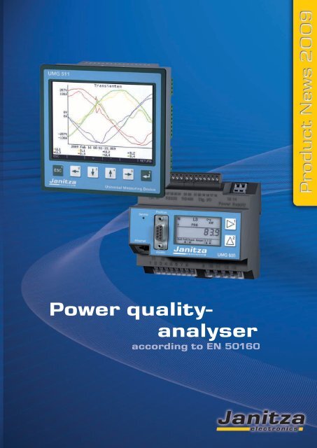
Power qualityanalyser
▼<br />
▼<br />
<strong>UMG</strong> <strong>511</strong><br />
Power quality analyser<br />
according to EN 50160<br />
The <strong>UMG</strong> <strong>511</strong> power quality analyser is particularly suitable for monitoring power quality according<br />
to standards such as the EN 50160. All power quality parameters are collected and analysed e.g. flicker,<br />
short term interruptions with fault recorder function, transients, harmonics up to the 63rd and inrush<br />
currents etc. Extensive communication possibilities e.g. RS 485 Modbus, Profibus, Ethernet (TCP/IP),<br />
BACnet, http, FTP, SMTP, SNTP, DNS ... allow cost effective and rapid integration in existing<br />
communication networks. Worldwide access to the embedded web server can be gained through a<br />
web browser. The GridVis software included in the content of delivery allows extensive analysis just<br />
by the click of a button.<br />
Areas of application<br />
Continuous monitoring of the power quality e.g. EN 50160<br />
<br />
<br />
Ethernet gateway for subordinate measurement points<br />
Analysis of electrical faults for network problems<br />
Monitoring of the internal distribution network according to EN 61000-4-7, 4-15, 4-30<br />
<br />
<br />
Report generator for EN 50160 analysis<br />
Remote control<br />
2
Power quality analyser<br />
<strong>UMG</strong> <strong>511</strong> Power quality analyser<br />
Added value with additional functions<br />
PQM - Power Quality Monitoring<br />
The <strong>UMG</strong> <strong>511</strong> power quality analyser serves for the purpose of continuous monitoring of the power quality<br />
e.g. in accordance with EN 50160. This serves for the purpose of monitoring the supply power quality<br />
from the energy supply side. The <strong>UMG</strong> <strong>511</strong> can also be used in applications for failure analysis on the consumer<br />
side and is also used as a preventative measure for network perturbations. A rapid, cost-optimised and<br />
reliable communication system can be developed through the Ethernet connection. The instrument’s own<br />
homepage offers you the opportunity to call up the data or configure the instrument directly using the embedded<br />
web server.<br />
The large number of digital inputs and outputs offer a variety of<br />
communication systems possibilities and allows connection to<br />
PLC systems and independent control tasks. The GridVis<br />
analysis software represents a fundamental part of the standard<br />
delivery. The GridVis can be used to practically trigger analysis<br />
in accordance with EN 50160 with the click of a button. The<br />
presentation of online data and the analysis of historical data is<br />
also a benefit for finding the root cause of network problems.<br />
Main features<br />
Measurement of power quality according to DIN EN 61000-4-30<br />
Measuring method as well as accuracy is class A<br />
Fourier analysis 1st to 63rd harmonic for U-LN, U-LL, I, P (consumption/supply) and Q (ind./cap.)<br />
Measurement of harmonics and interharmonics (U-LN, U-LL, I) according to DIN EN 61000-4-7<br />
Analysis and evaluation according to DIN EN 50160 with the contained programming and analysis<br />
software GridVis<br />
Flicker measurement according to DIN EN 61000-4-15<br />
Measurement in TN and TT grids (500V CATIII)<br />
4 voltage measuring inputs, 4 current measuring inputs<br />
Continuous sampling of voltage and current inputs with 20kHz<br />
Recording of more than 2000 different measurement parameter per measuring cycle (200ms)<br />
Detection of transients >50µs and storage with up to 16.000 samples<br />
Data logger / Event memory (256MB Flashdisk)<br />
8 digital inputs and 5 digital outputs<br />
Profibus DP/V0 alternatively RS 485 (Modbus RTU, Modbus-Master, optional BACnet)<br />
Ethernet (Web-Server, E-Mail, optional BACnet)<br />
Programming of customer specific applications in Jasic<br />
Applications<br />
The power quality analyser which is equipped with 4 current and voltage inputs collects and digitalises the<br />
effective values (True RMS) from currents and voltages in 40-70Hz (15-440Hz) networks. The integrated<br />
microprocessor calculates the electrical parameters from the sampling values. The relevant voltage can be defined<br />
as a phase-neutral or a phase-phase voltage for measurement in a three-phase system. The voltage serves<br />
the <strong>UMG</strong> <strong>511</strong> as a reference voltage for harmonic measurement, transient and event recording and for<br />
the flicker meter. A nominal current can be set using this for the measurement of electrical current events.<br />
The 4th current and voltage input represents a separate measurement system. However, it is generally used<br />
for measuring the current in the neutral or PE conductor or used for measuring a voltage difference between<br />
N and PE.<br />
3
▼<br />
Scope of operation<br />
Display examples<br />
The backlighted graphical display (5,7“) of the <strong>UMG</strong> <strong>511</strong> enables the presentation of measurement values in numerical form, as a bar chart<br />
or as a line graph. Selected displays can automatically be displayed in alternation (automatic display rotation). The instrument is programmed<br />
using userfriendly clear text menus or the GridVis software.<br />
Example of a <strong>UMG</strong> <strong>511</strong> connection illustration<br />
Main measurement<br />
Measurement in a four-phase network with main<br />
measurement and auxiliary measurement<br />
The <strong>UMG</strong> <strong>511</strong> has 4 measurement channels for<br />
current and voltage. The first three channels<br />
(main measurement) are intended for use in a<br />
three-phase system.<br />
Auxiliary measurement<br />
The auxiliary measurement can be used for measurement<br />
in a single-phase or symmetrical threephase<br />
system. Alternatively, the current input<br />
can be allocated to the three-phase system of the<br />
main measurement for measuring the neutralconductor<br />
current. For example, the voltage<br />
input could then be used for recording the voltage<br />
between the neutral conductor and PE. The<br />
auxiliary measurement provides all measurement<br />
parameters like in the main measurement<br />
(current, voltage, power, harmonics, transients,<br />
events and flicker).<br />
4
▼<br />
<strong>UMG</strong> <strong>511</strong><br />
Digital inputs and outputs<br />
The 8 digital inputs of the instrument can either be used for tariff switchover, for synchronisation, to start the recording, or as datalogger<br />
for other meter inputs for pulses. There are 8 programmable comparators available which can be allocated up to 4 measurement parameters<br />
as a limit value comparator. The digital outputs can also be programmed as a signal output for transients, events or as a pulse output.<br />
Interfaces<br />
<br />
RS485 protocols: Profibus DP or Modbus / RTU, Modbus-Gateway and BACnet<br />
<br />
Fast Ethernet 10/100Base-TX protocols: HTTP, NTP, Modbus TCP, Modbus over TCP, DHCP und BACnet.<br />
The measurement values and recorded data can be called up using the Ethernet (TCP/IP). Parameterisation of the instrument and analysis<br />
of the data is undertaken using GridVis software included in the delivery. The actual measurement values can be read out using the various<br />
field bus protocols (Modbus/RTU, Modbus/TCP, Profibus). An content of the digital inputs and outputs can be used for various.<br />
Data collection and recording<br />
The <strong>UMG</strong> <strong>511</strong> has an internal 256 MB flash memory for continuous recording of all measured data. The measurement value memory is<br />
freely configurable with reference to the measurement values which are to be recorded and the recording intervals. The recording interval is<br />
also the average time of the respective measurement value. In addition, the highest and lowest actual values (200ms average time) can also<br />
be recorded within the interval if you want to save the data as a graph y(t). Obviously it is also possible to store the measurement data in<br />
form of histogramms (distribution curve).<br />
The recording of transients and events is initiated by triggers. Transients are recorded from a period larger than 50µs. Events such as excess<br />
currents or under/overvoltage can be safely recorded from half a period. Events are recorded with up to 16000 (programmable) half cycles<br />
as effective value recorder.<br />
Software<br />
GridVis<br />
5 digital outputs for<br />
- Limit values I,U,P, transients, ...<br />
- Pulse outputs<br />
Interfaces<br />
Profibus / Modbus<br />
Ethernet<br />
10/100 Base-TX<br />
8 digital inputs<br />
- Tariff switchover<br />
- Start / stop recording<br />
- Meter pulses<br />
PLC<br />
Router<br />
256 MB memory<br />
- Amount of stored values: 10000k<br />
Modbus-gateway function<br />
- For external Modbus slave<br />
<strong>UMG</strong> 96S<br />
Meter<br />
5
▼<br />
Scope of operation<br />
Dimensional drawings<br />
Connection illustration<br />
View from below. All measurement<br />
data in mm.<br />
Ethernet connection<br />
Side view<br />
Typical connection<br />
6
▼<br />
<strong>UMG</strong> 605<br />
PQM - Power Quality Monitoring<br />
High performance power analyser<br />
for DIN rails<br />
according to EN 50160<br />
The <strong>UMG</strong> 605 power quality analyser is particularly suitable for monitoring power quality according<br />
to standards such as the EN 50160. All power quality parameters are collected and analysed e.g. flicker,<br />
short-term interruptions with fault recorder function, transients, harmonics up to 63rd and inrush<br />
currents etc. Extensive communication possibilities e.g. RS 485 Modbus, Profibus, Ethernet (TCP/IP),<br />
BACnet, http, FTP, SMTP, SNTP, DNS .... allow cost effective and rapid integration in existing communication<br />
networks. Worldwide access to the embedded web server can be gained through a web<br />
browser. The GridVis software included in the content of delivery allows extensive analysis just with<br />
the click of a button.<br />
Areas of application<br />
Continuous monitoring of the power quality e.g. EN 50160<br />
<br />
<br />
Ethernet gateway for subordinate measurement points<br />
Analysis of electrical faults for network problems<br />
Monitoring of the internal distribution network according to EN 61000-4-7, 4-15, 4-30<br />
<br />
<br />
<br />
Report generator for EN 50160 analysis<br />
Control tasks, e.g. depending on achieved measured values or limits<br />
Transducer for building automation or PLC systems<br />
7
▼<br />
Scope of operation<br />
<strong>UMG</strong> 605: the extra compact power analyser<br />
Added value through additional functions<br />
Thanks to state-of-the-art digital signal processor, it is possible to offer the<br />
power quality analyser <strong>UMG</strong> 605 at a very reasonable price. The high sampling<br />
rate enables a continuous measurement of more than 2000 measured<br />
values per measurement cycle (200ms). The <strong>UMG</strong> 605 power quality analyser<br />
serves the purpose of continuous monitoring of the power quality e.g.<br />
in accordance with EN 50160. This serves the purpose of monitoring the<br />
supply power quality from the energy supply side. The <strong>UMG</strong> 605 can also<br />
be used in applications for failure analysis on the consumer side and is also<br />
used as a preventative measure for network perturbations.<br />
Main Features<br />
Measurement of power quality according to DIN EN 61000-4-30<br />
Measurement method class A<br />
Fourier analysis 1st to 63rd harmonics for U-LN, U-LL, I, P (consumption/supply) and Q (ind./cap.)<br />
Measurement of harmonics and interharmonics (U-LN, U-LL, I)<br />
Analysis and evaluation according to DIN EN 50160 with the contained programming and analysis software GridVis<br />
Flicker measurement according to DIN EN 61000-4-15<br />
<br />
<br />
<br />
<br />
<br />
<br />
<br />
<br />
<br />
<br />
Measurement in IT and TT grids (300V CATIII)<br />
4 voltage measuring inputs, 4 current measuring inputs<br />
Continuous sampling of the voltage and current measuring inputs with 20kHz<br />
Recording of more than 2000 different measurement parameters per measuring cycle (200ms)<br />
Detection of transients >50µs and storage with up to 16.000 samples<br />
Data logger / event memory (128MB Flashdisk)<br />
2 digital inputs and 2 digital outputs<br />
Profibus DP/V0 alternatively RS 485 (Modbus RTU, Modbus-Master, optional BACnet)<br />
Ethernet (Web-Server, E-Mail, optional BACnet)<br />
Programming of customer specific applications in Jasic<br />
Applications<br />
The power quality analyser which is equipped with 4 current and voltage inputs collects and digitalises the effective values (True<br />
RMS) from currents and voltages in 40-70Hz (15-440Hz) networks. The integrated microprocessor calculates the electrical parameters<br />
from the sampling values. The relevant voltage can be defined as a phase-neutral or a phase-phase voltage for measurement<br />
in a three-phase system. The voltage serves the <strong>UMG</strong> 605 as a reference voltage for harmonic measurement, transient and event recording<br />
and for the flicker meter. A nominal current can be set using this for the measurement of electrical current events. However,<br />
it is generally used for measuring the current in the neutral or PE conductor or used for measuring a voltage difference between N<br />
and PE.<br />
8
▼<br />
<strong>UMG</strong> 605<br />
DIN rail mounting (6TE): reduction of installation<br />
costs<br />
Measurement equipment is usually installed in the low voltage main<br />
distribution as an integral measurement instrument for the switchgear<br />
cabinet door. Installation and connection costs are significantly<br />
reduced by the installation of the <strong>UMG</strong> 605 on a 35mm<br />
DIN rail. This means that the panel cut-out and wiring to the cabinet<br />
door is no longer necessary. In order to make use of the extensive<br />
functions of modern measuring equipment, the<br />
interconnection and central analysis of the data plays an important<br />
role. This means that the on-site display generally serves the purpose<br />
of the initialisation and service only.<br />
The decidedly compact <strong>UMG</strong> 605 is suitable for installation in low<br />
voltage main distribution panels and machines as well as in installation<br />
distribution boards which is particularly of interest for applications<br />
in building services engineering, information technology<br />
and data centres.<br />
Modern communication architecture<br />
through Ethernet: affordable, rapid and<br />
safe communication<br />
The costs for installation and communication (e.g. periphery for field<br />
buses) often surpass the costs of the measurement devices.<br />
By connecting the equipment to an existing Ethernet system, a fast,<br />
optimally priced and reliable communication system can be developed.<br />
Additional interfaces allow the integration of power analysers in<br />
PLC systems or in central building management systems. The use of<br />
open architecture offers the user a high amount of flexibility.<br />
Modbus gateway: the affordable<br />
connection of units without an<br />
Ethernet interface<br />
With the Modbus gateway function, simple Modbus RTU-units can<br />
be connected to the Ethernet using the <strong>UMG</strong> 605. For example, the<br />
<strong>UMG</strong> 605 can be used simultaneously as a gateway for subordinate<br />
measurement points or older units which already exist in the installation.<br />
Each unit with a Modbus RTU interface, where the data format<br />
and function codes match up, can be connected. Data can be marked<br />
and scaled.<br />
High-speed Modbus<br />
The device of the <strong>UMG</strong> 605 series can transfer data between the units using the RS485 interface<br />
at a speed of up to 921.5 kB/s.<br />
The e-mail and homepage inform you<br />
wherever you are…<br />
Who hasn’t experienced it before? You are hardly through the door and<br />
the telephone is already ringing. There are problems in production,<br />
computers are crashing and the energy supplies are lost.<br />
You have direct access to the extremely high performance homepage of<br />
the <strong>UMG</strong> 605 with a web browser and an IP address. Extensive information<br />
is already available to you on the homepage. Online data are<br />
available together with historical data and graphs recording events. The<br />
homepage can be used to directly convert the rates into costs and be exported<br />
as a csv file or printed. As an alternative, you can let yourself be<br />
informed by e-mail anywhere in the world if your energy supply becomes<br />
overloaded, if short-term interruptions to the voltage supplies<br />
bring your production processes to a standstill or unauthorised harmonics<br />
reduce the lifespan of equipment. The application possibilities<br />
are endless.<br />
9
RS<br />
<br />
RS<br />
<br />
<br />
<br />
<br />
<br />
<br />
<br />
<br />
<br />
<br />
<br />
<br />
<br />
<br />
<br />
<br />
<br />
<br />
<br />
<br />
<br />
<br />
<br />
<br />
<br />
<br />
<br />
<br />
<br />
<br />
<br />
<br />
<br />
<br />
<br />
<br />
▼<br />
Scope of operation<br />
Router PLC Software<br />
Networks<br />
IT, TN, TT networks<br />
3 phase and 4 phase networks<br />
Up to 4 single phase networks<br />
Interfaces<br />
Ethernet<br />
232<br />
485<br />
2 digital inputs<br />
Pulse input<br />
Logic input<br />
Status monitoring<br />
HT/LT switch over<br />
Emax (max. demand) resetting<br />
Profibus connection<br />
2 digital outputs<br />
Pulse output kWh/kvarh<br />
Switch output<br />
Limit value output<br />
Emax output<br />
Logic output<br />
(can be extended through external I/O<br />
modules)<br />
Communication<br />
Profibus (DP/V0)<br />
Modbus (RTU, UDP, TCP, gateway)<br />
TCP/IP<br />
BACnet<br />
HTTP (freely configurable homepage)<br />
FTP (file transfer)<br />
TFTP (automatic configuration)<br />
NTP (time synchronisation)<br />
SMTP (e-mail function)<br />
DHCP<br />
Measurement accuracy<br />
Class: 0.5S (…/5A) class<br />
Current: 0.2% rng<br />
Voltage: 0.2% rng<br />
Temperature<br />
measurement input<br />
PT 100, PT 1000, KTY 83, KTY 84<br />
Memory<br />
128 MB Flash<br />
16 MB RAM<br />
Power quality<br />
Harmonics up to 63rd<br />
Short-term interruptions<br />
Transient recorder (>50µs)<br />
Starting current (>10ms)<br />
Un-balance<br />
Half wave-effective value<br />
recordings (up to 4.5 min)<br />
Flicker<br />
Peak demand management<br />
64 stages for load shedding<br />
programming language<br />
10
▼<br />
<strong>UMG</strong> 605<br />
Connection<br />
illustration<br />
Dimensional drawing<br />
Front view<br />
Side view<br />
90 mm<br />
90 mm<br />
107,5 mm<br />
36 mm<br />
76 mm<br />
82 mm<br />
11
▼<br />
Scope of operation and types of variants<br />
Overview of product variants <strong>UMG</strong> <strong>511</strong> / <strong>UMG</strong> 605<br />
Three/four phase power quality analysers; current transformer .../1/5a; including GridVis programming and analysis software<br />
Supply voltage<br />
Interfaces<br />
95...265V AC,<br />
100...370V DC<br />
123...240V AC,<br />
175...340V DC<br />
50...130V AC,<br />
70...180V DC<br />
20...50V AC,<br />
20...70V DC<br />
4 voltage and<br />
4 current inputs<br />
Memory<br />
128/256 MB Flash<br />
digital inputs<br />
digital outputs<br />
1 temperature input<br />
RS 232<br />
RS 485<br />
Ethernet 100baseT<br />
Profibus DP V0<br />
Type<br />
Item number<br />
8 5 - - <strong>UMG</strong> <strong>511</strong> 52.19.001<br />
2 2 <strong>UMG</strong> 605 52.16.027<br />
2 2 <strong>UMG</strong> 605 52.16.028<br />
2 2 <strong>UMG</strong> 605 52.16.029<br />
Options (for all versions)<br />
Emax function application program (peak demand management) Emax 52.16.080<br />
BACnet communication BACnet 52.16.081<br />
- = not possible = contained<br />
General technical data<br />
<strong>UMG</strong> <strong>511</strong> <strong>UMG</strong> 605<br />
Supply voltage L-N, AC Refer to product variant overview Refer to product variant overview<br />
Overvoltage category 500V CATIII 300V CATIII<br />
Quadrants 4 4<br />
Continuous measurement yes yes<br />
8 channel scanning rate Per channel 20 kHz 20 kHz<br />
Weight 1kg 350g<br />
Dimensions L=144mm * B=144mm * H=81 mm L=107,5mm*B=90mm*H=76/82mm<br />
Mounting According to IEC EN 60999-1/DIN EN 50022 Front panel mounting 35mm DIN rail<br />
Working temperature range -10…50 °C -10…55 °C<br />
Connectable conductor (U/I) Single wire, multi-wire, fine-wire 0,08 - 2,5 mm² 0,08 - 2,5 mm²<br />
pin cable lugs, ferrule 1,5 mm² 1,5 mm²<br />
Protection class According to EN 60529 IP 50 front /IP 20 rear IP 20<br />
Measurement range<br />
<strong>UMG</strong> <strong>511</strong> <strong>UMG</strong> 605<br />
L-N voltage, AC (without voltage transformer) Free voltage transformer settings 5 …500 VAC 5…500 VAC<br />
L-L voltage, AC (without voltage transformer) Free voltage transformer settings 8…870 VAC 8…870 VAC<br />
Current (transformer: x/1 and x/5A) 0,005..6 A 0,005..6 A<br />
Frequency of mains 40 ..70 Hz 40 ..70 Hz<br />
Networks TN, TT IT, TN, TT<br />
Measurement in single/multi-phase networks<br />
1 ph, 2 ph, 3 ph, 4 ph<br />
and up to 4 x 1 ph<br />
1 ph, 2 ph, 3 ph, 4 ph<br />
and up to 4 x 1 ph<br />
Periphery<br />
<strong>UMG</strong> <strong>511</strong> <strong>UMG</strong> 605<br />
Digital inputs Status, logic or pulse input 8 2<br />
Digital outputs Switch logic output or pulse output 5 2<br />
Temperature measurement input PT100, PT1000, KTY83, KTY84 - 1<br />
Password protection Multilevel yes yes<br />
Demand management Optional 64 channels ja ja<br />
Software GridVis ja ja<br />
Features<br />
<strong>UMG</strong> <strong>511</strong> <strong>UMG</strong> 605<br />
Memory 256 MB 128 MB<br />
Clock +/- 1 min per month +/- 1 min per month<br />
Integrated logic Programming language Jasic ® Programming language Jasic ®<br />
Operating hour meter yes yes<br />
Weekly time switch Jasic ® Jasic ®<br />
12
▼<br />
<strong>UMG</strong> <strong>511</strong> und <strong>UMG</strong> 605<br />
Measurement values<br />
Voltage<br />
L1, L2, L3, L4, L1-L2, L2-L3, L1-L3<br />
<strong>UMG</strong> <strong>511</strong> Accuracy ±(0,1%)<br />
<strong>UMG</strong> 605 Accuracy ±(0,2% rdg + 0,02% rng)<br />
Current L1, L2, L3, L4 ±(0,2% rdg + 0,05% rng)<br />
Calculated sum current<br />
K-factor L1, L2, L3, L4 yes<br />
Three-phase current components Positive/ Negative/ Zero Phase Sequence yes<br />
Cos-phi, power factor L1, L2, L3, L4, Sum L1-L3, Sum L1-L4 yes<br />
Phase angle L1, L2, L3, L4 yes<br />
Effective energy (kWh)<br />
L1, L2, L3, L4, Sum L1-L3, Sum L1-L4:<br />
- Purchased effective energy (tariff 1, tariff 2)<br />
- Supplied effective energy (tariff 1, tariff 2)<br />
±(0,6% rdg + 0,05% rng)<br />
<strong>UMG</strong> <strong>511</strong> Class 0,2 (…/5A),<br />
<strong>UMG</strong> <strong>511</strong> Class 0,5S (…/1A),<br />
<strong>UMG</strong> 605 Class 0,5S (…/5A)<br />
<strong>UMG</strong> 605 Class 1 (…/1A)<br />
Reactive energy (kvarh)<br />
L1, L2, L3, L4, Sum L1-L3, Sum L1-L4:<br />
- Inductive reactive power (tariff 1, tariff 2) Class2<br />
- Capacitive reactive power<br />
Apparent energy (kVAh) L1, L2, L3, L4, Sum L1-L3, Sum L1-L4 yes<br />
Current/voltage wave form L1, L2, L3, L4 yes<br />
Frequency of mains<br />
Accuracy ±0,1% rdg<br />
Temperature measurement with <strong>UMG</strong> <strong>511</strong> not available Accuracy ±1,5% rng<br />
Average value<br />
yes<br />
Minimum and maximum values<br />
yes<br />
Power quality<br />
Harmonics order, 1.- 63rd<br />
Harmonics, even/odd<br />
Voltage L1, L2, L3, L4<br />
Measure value > 3% of measuring range<br />
Measure value < 3% of measuring range<br />
Interharmonics Current, voltage L1, L2, L3, L4 yes<br />
Distortion factor THD-U in % L1, L2, L3, L4 yes<br />
Distortion factor THD-I in % L1, L2, L3, L4 yes<br />
Positive/negative/zero system<br />
yes<br />
Actual flicker value L1, L2, L3, L4 yes<br />
Short term flicker value L1, L2, L3, L4 yes<br />
Long term flicker value L1, L2, L3, L4 yes<br />
Transients 50 µs<br />
Trigger events 10 ms yes<br />
Inrush currents 10 ms yes<br />
Event recorder<br />
yes<br />
Accuracy ± 5% rdg<br />
Accuracy ± 0,05 rng)<br />
Communication<br />
Interfaces <strong>UMG</strong> <strong>511</strong> <strong>UMG</strong> 605<br />
RS 232 9.6, 19.2, 38.4, 115.2 kbps no yes<br />
RS 485 9.6, 19.2, 38.4, 76.8, 115.2, 921.6 kbps yes yes<br />
Profibus DP Plug, sub D 9-pole up to 12Mbps yes yes<br />
Ethernet 10/100 Base- TX RJ-45 sockets yes yes<br />
Protocols<br />
Modbus RTU yes yes<br />
Profibus DP V0 yes yes<br />
Modbus TCP yes yes<br />
Modbus over TCP yes yes<br />
Modbus-Gateway yes yes<br />
HTTP Homepage (configurable) yes yes<br />
SMTP E-Mail yes yes<br />
SNTP Time synchronisation yes yes<br />
TFTP Automatic configuration yes yes<br />
FTP File Transfer yes yes<br />
DHCP yes yes<br />
BACnet / IP oder MSTP yes, option yes, option<br />
13
▼<br />
GridVis Software<br />
Software<br />
The GridVis software is included in the standard content of delivery of the <strong>UMG</strong> <strong>511</strong> and <strong>UMG</strong> 605 measurement devices. The software<br />
helps you to read out and graphically present measurement data either online as actual values or from the measurement value memory. The<br />
data can be displayed as a line graph, bar chart or histogram. The EN 50160 and EN 61000-2-4 analysis tools allow the rapid analysis of<br />
both standards. At a glance, it is easier to identify whether the standards are fulfilled throughout the respective measurement period and a<br />
copy can be directly created on paper or as a PDF document.<br />
Ill.: Screenshot GridVis Software with various graphs<br />
Ill.: Automatically generated power quality report<br />
14
▼<br />
<strong>UMG</strong> <strong>511</strong> und <strong>UMG</strong> 604<br />
Grid visualisation software<br />
The data gained from various measurement points must be collected, saved, visualised and made available. The GridVis software contained<br />
in the <strong>UMG</strong> 605 package allows<br />
<br />
<br />
<br />
<br />
Parameterisation and programming of <strong>UMG</strong> measurement devices<br />
Visualisation of the measurement values with topological view<br />
Automatic download of the measurement data<br />
Jasic programming<br />
<br />
<br />
<br />
<br />
Data management<br />
Online analysis tools<br />
Analysis tools for historic data<br />
Transient-, event-, flagbrowser<br />
Visualisation, topological view<br />
GridVis allows an individually adaptable visualisation of online data. The topological view provides a rapid overview of energy distribution<br />
with the possibility of localising power faults by comparing the individual measurement points and by offering the possibility to monitor the<br />
defined tolerances at a glance.<br />
Customer specific solutions can be quickly and simply implemented through uploading of graphic documents (standard formats such as JPG)<br />
with circuit diagrams, production lines or construction plans and incorporating the respective measurement units by drag and drop into their<br />
actual locations. Limit value excesses (e.g. THD-U is too high) and the status of inputs and outputs can also be displayed.<br />
Online values and analysis<br />
of historic data<br />
With the graphic line writer function, GridVis enables<br />
rapid online presentation of the selected measurement values.<br />
In this function, the graph is continuously expanded<br />
with new measurement values. For example, load profiles<br />
can be presented through the analysis of historic data in<br />
order to produce exact consumption analysis for optimised<br />
electricity supply contracts. Fault analysis through the comparison<br />
of various parameters can also be achieved with a<br />
few mouse clicks.<br />
Graphic programming<br />
The graphic programming option for user programs is completely<br />
new in the field of digital power analysers. Programs<br />
specific to the application can be created with this method<br />
such as the free programming of inputs and outputs, monitoring<br />
of processes or the issue of reports when defined limit<br />
values are achieved. In addition to the operator-friendly graphic<br />
programming, the user is also free to program the Jasic ®<br />
source code directly.<br />
programming language<br />
The Jasic ® programming language offers brand new opportunities.<br />
The user is no longer tied to the functions<br />
which are fixed integrations in the unit; the unit can be expanded<br />
to include more functions. Up to seven of these<br />
freely definable user programs can be processed simultaneously<br />
in the <strong>UMG</strong> devices.<br />
Ill.: Graphical programming<br />
15
Item no.: 33.03.636 04/2009<br />
Representative<br />
Janitza elec tronics GmbH<br />
Vor dem Polstück 1<br />
D- 35633 Lahnau<br />
Germany<br />
Tel.: 0049 (0) 6441 9642- 0<br />
Fax: 0049 (0) 6441 9642-30<br />
info@janitza.de<br />
w w w.janitza.de<br />
Technical alterations subject to change.