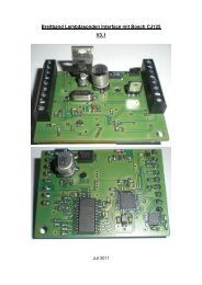
Technical Product Information - Breitband-Lambda
Technical Product Information - Breitband-Lambda
Technical Product Information - Breitband-Lambda

You also want an ePaper? Increase the reach of your titles
YUMPU automatically turns print PDFs into web optimized ePapers that Google loves.
Produkt / <strong>Product</strong>:<br />
Typ / Type:<br />
Bemerkung / Comment:<br />
Nr.<br />
Index<br />
Seite<br />
Page<br />
Änderung<br />
Revision<br />
1 - Erstausgabe / First Edition<br />
Contents<br />
<strong>Technical</strong> <strong>Product</strong> <strong>Information</strong><br />
Y 258 E00 015e<br />
Seite/Page 1 von/of 13<br />
Datum/Date 14.6.2005<br />
Planar Wide Band <strong>Lambda</strong> Sensor<br />
LSU4.9<br />
translation to English 26.8.05<br />
All data given in this document are nominal values<br />
and might be subject of change at all time.<br />
Datum GS-EX/ENG6- GS-EX/ENG6 GS-EX/ENG<br />
Date<br />
Ham<br />
14.6.05 gez Hamann gez Meier gez.<br />
Stanglmeier<br />
1. Characteristics 2<br />
2. Application conditions 5<br />
3. Functional values 7<br />
4. Installation instructions 9<br />
5. General operating instructions 12<br />
©Alle Rechte bei Robert Bosch GmbH, auch für den Fall von Schutzrechtsanmeldungen. Jede Verfügungsbefugnis, wie Kopier- und Weitergaberecht, bei uns.<br />
©Robert Bosch GmbH reserves all rights even in the event of industrial property.We reserve all rights of disposal such as copying and passing on to third parties
General<br />
<strong>Technical</strong> <strong>Product</strong> <strong>Information</strong><br />
Y 258 E00 015e<br />
Seite/Page 2 von/of 13<br />
Datum/Date 14.6.2005<br />
The wide band lambda sensor LSU is a planar ZrO2 dual cell limiting current<br />
sensor with an integrated heater. It is used to measure the oxygen content<br />
and the λ-value of exhaust gases in automotive engines (gasoline and diesel).<br />
Its monotonic output signal in the range of λ=0.65 to air makes the<br />
LSU capable of being used as an universal sensor for λ=1 measurement as<br />
well as for other λ ranges.<br />
The connector module contains a trimming resistor, which defines the<br />
characteristics of the sensor and is necessary for the sensor function.<br />
The wide band sensor LSU operates only in combination with a special<br />
LSU control unit (e.g. AWS control box, LA4 or CJ125 IC).<br />
1. Characteristics<br />
1.1 Circuit of LSU and control unit<br />
O 2−<br />
O 2, CO, HC, H 2<br />
1.2 Electrical connection:<br />
Sensor Cell AWS<br />
O 2−<br />
H -<br />
H +<br />
APE ← Ip<br />
red IP<br />
Pin1: Pumping Current APE red<br />
Pin2: Virtual Ground IPN yellow<br />
Pin3: Heater Minus H- white<br />
Pin4: Heater Vbatt H+ grey<br />
Trimming Resistor<br />
30-300 Ohm<br />
green<br />
Pin5: Trim Current RT green<br />
Pin6: Nernst Voltage RE+ black<br />
IPN<br />
RE<br />
← Ip meas<br />
Measuring<br />
Resistance 61.9 Ohm<br />
Reference<br />
Voltage<br />
450 mV<br />
R i-control<br />
©Alle Rechte bei Robert Bosch GmbH, auch für den Fall von Schutzrechtsanmeldungen. Jede Verfügungsbefugnis, wie Kopier- und Weitergaberecht, bei uns.<br />
©Robert Bosch GmbH reserves all rights even in the event of industrial property.We reserve all rights of disposal such as copying and passing on to third parties<br />
yellow<br />
black<br />
white<br />
grey<br />
IA<br />
VM=2,5V<br />
U N<br />
+<br />
−<br />
R V<br />
+<br />
−<br />
V CC<br />
20 µA Reference Pump Current<br />
−<br />
+
1.3 Sensor element<br />
<strong>Technical</strong> <strong>Product</strong> <strong>Information</strong><br />
Y 258 E00 015e<br />
Seite/Page 3 von/of 13<br />
Datum/Date 14.6.2005<br />
The heater supply voltage must be controlled, so that the temperature of<br />
the sensor is kept at the operation point. The temperature is measured by<br />
measuring the internal resistance of the sensor’s Nernst cell Ri,N<br />
Nominal internal resistance of λ=1 Nernst cell Ri,N<br />
for new sensors (operating and calibration point)<br />
(measured with AC f = 1...4 kHz) 300 Ω<br />
Max. current load of λ=1 Nernst cell<br />
Continuous AC (f = 1...4 kHz) ≤ 250 µA<br />
for RI,N measurement<br />
Recommended value for reference pumping current<br />
continuous = 20 µA<br />
Max. pumping current into pump cell (Ip)<br />
- for rich gas signal (λ≥0,65) ≥ -9 mA<br />
- for lean gas signal (air) ≤ 6 mA<br />
1.4 Isolation resistance<br />
(all values for new sensors in static air, heater off)<br />
- between housing and each heater- and<br />
sensor circuit connector pin at room<br />
temperature ≥ 30 MΩ<br />
- between sensor signal circuit and heater<br />
circuit at 600°C hexagon temperature ≥ 1 MΩ<br />
- between sensor signal pin APE and housing<br />
at 600°C hexagon temperature: ≥ 100 kΩ<br />
©Alle Rechte bei Robert Bosch GmbH, auch für den Fall von Schutzrechtsanmeldungen. Jede Verfügungsbefugnis, wie Kopier- und Weitergaberecht, bei uns.<br />
©Robert Bosch GmbH reserves all rights even in the event of industrial property.We reserve all rights of disposal such as copying and passing on to third parties
1.5 Heater supply<br />
<strong>Technical</strong> <strong>Product</strong> <strong>Information</strong><br />
Nominal voltage: 7.5 V<br />
Y 258 E00 015e<br />
Seite/Page 4 von/of 13<br />
Datum/Date 14.6.2005<br />
Nominal heater power at 7.5 V heater supply<br />
at thermal equilibrium in air: approx. 7.5 W<br />
Nominal heater cold resistance at room temp. 3.2 Ω<br />
for new sensor, including cable and connector<br />
Minimum heater cold resistance at -40°C: 1.8 Ω<br />
1.6 When the heater is switched on, heater power must be limited as follows:<br />
effective heater voltage<br />
VHeff [V]<br />
13 V<br />
8.5V<br />
heater power reduced<br />
during condensation<br />
water phase<br />
//<br />
maximum<br />
ramp rate<br />
= 0.4V/s<br />
max. initial value<br />
8.5V<br />
← application specific → time after heater start<br />
Maximum permissible heat up rate with limited heater power to reduce the thermal stresses in<br />
the heat-up phase<br />
During the condensation water phase the heater power must be limited to<br />
rule out thermo shock damage of the sensor ceramic.<br />
Heater voltage during condensation water phase VH,eff ≤ 2 V<br />
Maximum permissible effective heater voltage VH,eff<br />
to reach the operating point<br />
- short time ≤ 30sec (200h cumulated time): ≤ 13 V<br />
- continuous: ≤ 12 V<br />
Maximum system supply voltage Vbatt,max ≤ 16.5 V<br />
Minimum system supply voltage ≥ 10.8 V<br />
at this system supply voltage the function of the sensor is given in<br />
typical applications. This must still be tested in the resp. application.<br />
Minimum frequency of heater voltage control ≥ 20 Hz<br />
- recommended value: ≥ 100 Hz<br />
Note: the use of the sensor with 24V power systems is<br />
not permissible except if a voltage converter system is used.<br />
Note: duty cycle = (VH,eff / Vbatt) 2<br />
©Alle Rechte bei Robert Bosch GmbH, auch für den Fall von Schutzrechtsanmeldungen. Jede Verfügungsbefugnis, wie Kopier- und Weitergaberecht, bei uns.<br />
©Robert Bosch GmbH reserves all rights even in the event of industrial property.We reserve all rights of disposal such as copying and passing on to third parties<br />
//<br />
operating point reached<br />
application specific<br />
max. value<br />
13Volt
2. Application conditions<br />
<strong>Technical</strong> <strong>Product</strong> <strong>Information</strong><br />
Y 258 E00 015e<br />
Seite/Page 5 von/of 13<br />
Datum/Date 14.6.2005<br />
2.1 Temperature measurements<br />
Temperature measurements are performed with a special sensor equipped with<br />
NiCrNi thermocouples, see sketch. Sensor Type "MABCD" has measurement<br />
points at the upper side of the PTFE formed hose (Tupperhose), the cable grommet<br />
(Tgrommet), the hexagon of the sensor housing (Thexagon) and for the exhaust<br />
gas temperature (Texhaustgas). These sensors are available from Bosch.<br />
TExhaustgas TGrommet TUpperhose<br />
THexagon<br />
2.2 Operating temperatures<br />
Exhaust gas (TExhaustgas): ≤ 930°C<br />
Hexagon of the sensor housing (THexagon): ≤ 600°C<br />
Cable grommet (PTFE formed hose)<br />
- sensor side (TGrommet): ≤ 250°C<br />
- cable side (upperhose crimp, TUpperhose): ≤ 200°C<br />
Cable and protective sleeve: ≤ 250°C<br />
Connector: ≤ 120°C<br />
2.3 Maximum temperatures<br />
2.3.1 (max. 250 h accumulated over lifetime)<br />
Exhaust gas (TExhaustgas): ≤ 1030°C<br />
Hexagon of the sensor housing (THexagon): ≤ 680°C<br />
2.3.2 (max. 40 h accumulated over lifetime)<br />
Cable grommet (PTFE formed hose)<br />
- sensor side (TGrommet): ≤ 280°C<br />
- cable side (upperhose crimp, TUpperhose): ≤ 230°C<br />
Cable and protective sleeve: ≤ 280°C<br />
©Alle Rechte bei Robert Bosch GmbH, auch für den Fall von Schutzrechtsanmeldungen. Jede Verfügungsbefugnis, wie Kopier- und Weitergaberecht, bei uns.<br />
©Robert Bosch GmbH reserves all rights even in the event of industrial property.We reserve all rights of disposal such as copying and passing on to third parties
<strong>Technical</strong> <strong>Product</strong> <strong>Information</strong><br />
2.4 Exhaust gas pressure (absolute pressure)<br />
- continuous: ≤ 2.5 bar<br />
- short time, max. 250h cumulated over lifetime ≤ 4 bar<br />
Y 258 E00 015e<br />
Seite/Page 6 von/of 13<br />
Datum/Date 14.6.2005<br />
Notes:<br />
If the operating temperature ( 2.2) or the max. continuous exhaust gas<br />
pressure ( 2.4) is exceeded, the sensor accuracy might be limited during<br />
this time.<br />
2.5 Permissible vibrations<br />
Stochastic vibrations: (peak level) ≤ 1000 m/s 2<br />
Sinusoidal vibrations: ≤ 300 m/s 2<br />
2.6 Corrosion, humidity<br />
The lambda sensor has been developed and tested for use in automotive vehicles,<br />
e.g.<br />
- damp heat cycling acc. to IEC 68-2-30 test Db (21 days, 40°C)<br />
- salt mist test acc. to IEC 68-2-11 test Ka, test time 288 h<br />
- temperature cycling test acc. to IEC 68-2-14 test Na,<br />
250 cycles -40°C / 130°C<br />
- sulfur dioxide test with general condensation of moisture acc. to DIN EN<br />
ISO 6988, 6 cycles of 24h<br />
- submergence test IPx7 acc. to IEC 529<br />
2.7 Permissible fuel additives<br />
In accordance with DIN EN228 for commercially available unleaded fuel or<br />
EN590 for diesel fuel.<br />
Contamination by other fuels, additives or oil consumption must be determined<br />
by the customer by the way of adequate large-scale tests.<br />
©Alle Rechte bei Robert Bosch GmbH, auch für den Fall von Schutzrechtsanmeldungen. Jede Verfügungsbefugnis, wie Kopier- und Weitergaberecht, bei uns.<br />
©Robert Bosch GmbH reserves all rights even in the event of industrial property.We reserve all rights of disposal such as copying and passing on to third parties
3. Functional values<br />
<strong>Technical</strong> <strong>Product</strong> <strong>Information</strong><br />
Y 258 E00 015e<br />
Seite/Page 7 von/of 13<br />
Datum/Date 14.6.2005<br />
All data must be regarded as nominal values, measured under the following<br />
conditions:<br />
The sensor is operated with circuit as in section 1.1. The heater power is<br />
closed-loop controlled, so that the nominal sensor internal resistance is<br />
reached. The measurement is done in a lab test bench at pgas=1013hPa.<br />
Changes in the test gas composition, especially of the H2-concentration,<br />
will have an influence on the characteristics of the sensor. These influences<br />
are stronger in rich gas than under lean gas conditions.<br />
3.1 Nominal characteristic line<br />
I P meas / mA<br />
3,000<br />
2,500<br />
2,000<br />
1,500<br />
1,000<br />
0,500<br />
0,000<br />
0 5 10 15 20 25<br />
-0,500<br />
IP meas / mA<br />
1,500<br />
1,000<br />
0,500<br />
-0,500<br />
-1,000<br />
-1,500<br />
-2,000<br />
gas: O 2 in N 2<br />
calibration point<br />
O 2-concentration x O2 / %<br />
0,000<br />
0,70 0,80 0,90 1,00 1,1 1,20 1,30 1,40 1,50 1,60 1,70 1,80 1,90 2,00 2,10 2,20 2,30 2,40 2,50<br />
rich gas mixture of synthetic gas<br />
9%CO, 7%H2, 7%CO2 in N2<br />
lean gas: O 2 in N2<br />
λ = (xO2 / 3 +1) / (1-4.77*xO2 ) for H/C=2<br />
O2-conc. xO2/% 3.0 6.0 8.29 12.0 20.95<br />
λ-value 0.65 0.70 0.80 0.90 1.016 1.18 1.43 1.70 2.42 air<br />
Ip,meas/mA -2.22 -1.82 -1.11 -0.50 0.00 0.33 0.67 0.94 1.38 2.54<br />
©Alle Rechte bei Robert Bosch GmbH, auch für den Fall von Schutzrechtsanmeldungen. Jede Verfügungsbefugnis, wie Kopier- und Weitergaberecht, bei uns.<br />
©Robert Bosch GmbH reserves all rights even in the event of industrial property.We reserve all rights of disposal such as copying and passing on to third parties<br />
λ
<strong>Technical</strong> <strong>Product</strong> <strong>Information</strong><br />
3.2 Time to activity (light-off time)<br />
Y 258 E00 015e<br />
Seite/Page 8 von/of 13<br />
Datum/Date 14.6.2005<br />
Guide value for the time to activity after switching ≤ 10 s<br />
on the sensor heater (“light-off time”)<br />
3.3 Pressure dependency of the sensor signal<br />
A change of the exhaust gas pressure leads to a deviation of the sensor<br />
signal, which can be approximately described as follows:<br />
25,0%<br />
20,0%<br />
15,0%<br />
10,0%<br />
5,0%<br />
0,0%<br />
-5,0%<br />
-10,0%<br />
-15,0%<br />
-20,0%<br />
∆Ip/Ip(1013 hPa)<br />
lambda > 1<br />
lambda < 1<br />
-25,0%<br />
0,5 0,7 0,9 1,1 1,3 1,5 1,7 1,9 2,1 2,3 2,5<br />
absolute pressure<br />
Absolut-Druck in [bar]<br />
3.4 Temperature dependency of the sensor signal and the internal resistance of<br />
the Nernst-cell Ri,N<br />
A temperature change of the sensor ceramic gives a deviation of the sensor<br />
output signal of approx. ∆IP,meas/IP,meas = 4%/100°C<br />
The temperature is known by measuring the internal resistance of the Nernst<br />
cell RI,N and the following curve:<br />
Nernst cell resistance RIN / Ohm<br />
1000<br />
100<br />
operating point<br />
RI,N = 300Ω,<br />
Tceramic = 780°C<br />
10<br />
600 700 800 900<br />
Tceramic / °C<br />
1000 1100 1200<br />
©Alle Rechte bei Robert Bosch GmbH, auch für den Fall von Schutzrechtsanmeldungen. Jede Verfügungsbefugnis, wie Kopier- und Weitergaberecht, bei uns.<br />
©Robert Bosch GmbH reserves all rights even in the event of industrial property.We reserve all rights of disposal such as copying and passing on to third parties
4. Installation instructions<br />
<strong>Technical</strong> <strong>Product</strong> <strong>Information</strong><br />
Y 258 E00 015e<br />
Seite/Page 9 von/of 13<br />
Datum/Date 14.6.2005<br />
The lambda sensor has been developed and tested for use in automotive engines<br />
only.<br />
The sensor installation point and the sensor functionality in the full system<br />
must be assured sufficiently by the customer through appropriate vehicle<br />
tests under realistic conditions of use.<br />
4.1 Installation in the exhaust system must be at a point guaranteeing representative<br />
exhaust gas composition whilst also satisfying the specified temperature<br />
limits.<br />
4.2 The heater power must always be switched on power controlled (e.g. duty<br />
cycled heater power), starting with a maximum ramp-up duty cycle as shown<br />
in the diagram in section 1.6. This is necessary to reduce thermal stress<br />
of the sensor element during cold starts due to high peak power in the<br />
first seconds.<br />
4.3 The sensor ceramic element is heated up quickly after heater start.<br />
After heating up the ceramic all occurrence of condensation water, which<br />
could damage the hot ceramic, must be ruled out.<br />
To allow early heating of the sensor to reach a fast sensor activity, the<br />
sensor installation location design must be selected in a way to minimize<br />
exhaust-side stressing of the sensor with condensation water.<br />
If this is not possible by design measures, the start of the sensor heater<br />
must be delayed until demonstrably no more condensation water appears.<br />
4.3.1 Design measures:<br />
- Locate sensor as close to the engine as possible, respecting max. allowed<br />
temperature range<br />
- The exhaust pipe in front of the sensor must not contain any pockets,<br />
projections, protrusions, edges flex-tubes etc. to avoid accumulation of<br />
condensation water. A downwards slope of the pipe is recommended.<br />
- Make sure, that the front hole of the double protection tube does not<br />
point against exhaust gas stream.<br />
- Attempt to achieve rapid heating-up of the exhaust pipes in the area in<br />
front of the sensor and also of the complete sensor thread boss area, to<br />
avoid developing of condensation water<br />
- The sensor thread boss must be designed as shown in 4.9 to reach a rapid<br />
heat up of the sensor protection tube area. Make sure, that the protection<br />
tube is fully reaching into the exhaust gas stream.<br />
4.3.2 System measures:<br />
- Never switch on sensor heating resp. control unit before engine start.<br />
- Delay of sensor heater start or reduced heater power (see section 1.6)<br />
©Alle Rechte bei Robert Bosch GmbH, auch für den Fall von Schutzrechtsanmeldungen. Jede Verfügungsbefugnis, wie Kopier- und Weitergaberecht, bei uns.<br />
©Robert Bosch GmbH reserves all rights even in the event of industrial property.We reserve all rights of disposal such as copying and passing on to third parties
<strong>Technical</strong> <strong>Product</strong> <strong>Information</strong><br />
Y 258 E00 015e<br />
Seite/Page 10 von/of 13<br />
Datum/Date 14.6.2005<br />
4.4 Installation angle must be inclined at least 10° towards horizontal (electrical<br />
connection upwards). Thus preventing the collection of liquids between<br />
sensor housing and sensor element during the cold start phase.<br />
The angle against the exhaust gas stream should be aimed as 90°. Maximum<br />
inclination should be 90°+15° (protection tube towards gas stream) or<br />
90°-30°.<br />
Other installation angles must be inspected and tested individually.<br />
4.5 Avoid excessive heating up of sensor cable grommet, particularly when the<br />
engine has been switched off after running under max. load conditions.<br />
4.6 The use of cleaning/greasing fluids or evaporating solids at the sensor<br />
plug connection is not permitted.<br />
4.7 Assembly with special high temperature resistant grease on the screw-in<br />
thread (e.g. Bosch-No. 5 964 080 112).<br />
4.8 Tightening torque: 40-60 Nm, material characteristics and strength of the<br />
thread must be appropriate.<br />
4.9 Recommended material for the<br />
thread boss in the exhaust pipe:<br />
Temperature resistant stainless<br />
steel, e. g.<br />
X 5 CrNi 18 10, DIN 17440 1.4301<br />
or 1.4303 or SAE 30304 or SAE<br />
30305 (US standard)<br />
Thread boss dimensions should be<br />
as in sketch, note that sensor<br />
thread must be covered completely.<br />
� � � 4 � !<br />
Recommendation(*): For hot<br />
applications (THexagon>600°C or<br />
Tgas>930°C) the thread boss should<br />
be min. 13mm to avoid overheating<br />
of the protection tube welding<br />
and to cool down the sensor hexagon.<br />
If the length is ≥16mm (max. 22mm permissible) the danger of thermo shock<br />
will be increased due to condensation water formation inside the protection<br />
tube.<br />
©Alle Rechte bei Robert Bosch GmbH, auch für den Fall von Schutzrechtsanmeldungen. Jede Verfügungsbefugnis, wie Kopier- und Weitergaberecht, bei uns.<br />
©Robert Bosch GmbH reserves all rights even in the event of industrial property.We reserve all rights of disposal such as copying and passing on to third parties<br />
� #<br />
� & �#<br />
� !<br />
� & N �#<br />
!<br />
� E� � �#<br />
� � E� � !
<strong>Technical</strong> <strong>Product</strong> <strong>Information</strong><br />
Y 258 E00 015e<br />
Seite/Page 11 von/of 13<br />
Datum/Date 14.6.2005<br />
4.10 The sensor and sensor connection must be covered when underbody sealant<br />
(wax, tar etc.) or spray oil is applied to the vehicle.<br />
4.11 The influence of contamination which enters the exhaust gas through the<br />
intake air or as a result of fuel, oil, sealing materials etc., and thus<br />
reaches the λ-sensor, is application specific and must be determined by<br />
customer tests.<br />
4.12 The sensor must not be exposed to strong mechanical shocks (e.g. while the<br />
sensor is installed). Otherwise the sensor element may crack without visible<br />
damage to the sensor housing.<br />
4.13 To ensure the necessary minimum reference pumping current, the isolation of<br />
the vehicle wire harness including all connections must be guaranteed. The<br />
minimum isolation resistance under all ambient conditions (temperature, humidity)<br />
over the whole vehicle life time must be ≥ 2MΩ between all sensor<br />
signal pins.<br />
4.14 Underfloor installation of the sensor at a distance from the engine requires<br />
an additional check of the following points:<br />
- positioning of the sensor with respect to stone impact hazard<br />
- positioning and fixing of cable and connector with respect to mechanical<br />
damage, cable bending stress and thermal stress.<br />
4.15 The PTFE formed hose is part of the reference air volume of the sensor and<br />
must be kept sealed and undamaged. For installation, the minimum bending<br />
radius of the hose must be 20mm (for long PTFE hose) resp. 12mm (for short<br />
hose). Keep the PTFE formed hose away from sharp edges and avoid contact/friction<br />
with frame/engine assembly.<br />
The first fixing point for the cable to the car body should be 200mm to<br />
400mm after the end of the PTFE formed hose, depending on movement of the<br />
exhaust system.<br />
4.16 The sensor should not be exposed to continuous, one-sided dripping of<br />
water, e.g. by the air conditioning condensation water outlet. The thermal<br />
stress could lead to mechanical damage of the sensor.<br />
4.17 The sensors must be stored in the original packaging at a dry place.<br />
Maximum storage time is 2 years.<br />
©Alle Rechte bei Robert Bosch GmbH, auch für den Fall von Schutzrechtsanmeldungen. Jede Verfügungsbefugnis, wie Kopier- und Weitergaberecht, bei uns.<br />
©Robert Bosch GmbH reserves all rights even in the event of industrial property.We reserve all rights of disposal such as copying and passing on to third parties
5. General operating instructions<br />
<strong>Technical</strong> <strong>Product</strong> <strong>Information</strong><br />
Y 258 E00 015e<br />
Seite/Page 12 von/of 13<br />
Datum/Date 14.6.2005<br />
5.1 Conditions for connection and electrical operation of the sensor<br />
It must be assured, that when the sensor is operated, the connection to the<br />
control unit is not disconnected during operation, or that the control unit<br />
diagnosis recognizes a failing connection.<br />
It is also not allowed, to disconnect or to connect the sensor to the<br />
control unit or ECU while the sensor or control unit is being operated.<br />
Background: if the signal of the λ=1 cell is missing (e.g. connection<br />
failure), the internal control circuit can not operate correctly, so that<br />
- an excessive pumping voltage with wrong polarization can destroy the<br />
pumping cell of the sensor<br />
- the sensor element can be destroyed by overheating, when the closed loop<br />
heater control is not able to measure the ceramic temperature<br />
The control unit may only be switched on after the sensor is connected<br />
completely.<br />
The sensor cables may never be connected in the wrong way or wrong polarity,<br />
otherwise the sensor might be destroyed.<br />
5.2 Use without control unit<br />
The sensor might stay in the exhaust gas stream for a short time also if<br />
the control unit is not connected. Connect and disconnect only, when the<br />
control unit is switched off.<br />
5.3 Use of LSU outside of the exhaust gas system<br />
The sensor can also be used outside an exhaust gas system, e.g. in air.<br />
When used in a stoichiometric (λ = 1) or rich gas (λ < 1), e.g. measurement<br />
gas in the test bench, it must be assured, that enough O2 donators are<br />
available in the gas to allow the pumping cell to work. Otherwise the ZrO2<br />
ceramic of the sensor can be reduced and the sensor destroyed.<br />
The O2 donator may be free oxygen (non-equilibrium measurement gas), H2O or<br />
CO2.<br />
Guide values: H2O: ≥ 2 vol %<br />
CO2: ≥ 2 vol %<br />
5.4 Electrical heating of the sensor<br />
The sensor heater may never be connected directly to battery voltage. It<br />
must always be controlled by the LSU control unit or the vehicle ECU. Heating<br />
the sensor before the engine is started is not allowed.<br />
©Alle Rechte bei Robert Bosch GmbH, auch für den Fall von Schutzrechtsanmeldungen. Jede Verfügungsbefugnis, wie Kopier- und Weitergaberecht, bei uns.<br />
©Robert Bosch GmbH reserves all rights even in the event of industrial property.We reserve all rights of disposal such as copying and passing on to third parties
<strong>Technical</strong> <strong>Product</strong> <strong>Information</strong><br />
5.5 General function test (at vehicles, in workshops)<br />
Y 258 E00 015e<br />
Seite/Page 13 von/of 13<br />
Datum/Date 14.6.2005<br />
The following tests can be done as a rough check of the sensor function<br />
(operation with control unit):<br />
Plausibility check in rich exhaust gas:<br />
- sensor signal: rich (output voltage in AWS < 2.5V<br />
Plausibility check on air:<br />
- sensor signal: air signal (output voltage in AWS ≥ 5.6V)<br />
Heater cold resistance at room temperature:<br />
- resistance measurement with multimeter between grey and white cable,<br />
sensor not connected to control unit:<br />
RH,cold = 2,5 ... < 5 Ω (sensor at room temperature)<br />
Visual inspection for mechanical damage<br />
5.6 Sensor characteristic at low or high exhaust gas temperatures<br />
Hot exhaust gas with a temperature above the operation temperature of the<br />
ceramic can lead to a deviation of the ceramic temperature and the sensor<br />
output signal.<br />
5.7 Note for calculation of the sensor signal IP,meas when using a control unit<br />
AWS or CJ125:<br />
Output voltage AWS : VAWS [V] = 2.5 + 1.648 * IP,meas [mA]<br />
Output voltage CJ125 : VCJ125 [V] = 1.5 + (61.9/1000*v) * IP,meas [mA]<br />
with v=17 (standard measuring range λ=0.8...air) or v=8 (measuring range<br />
λ=0.65...air).<br />
The amplification factor (v) can be switched between v=8 and v=17 in the<br />
CJ125.<br />
©Alle Rechte bei Robert Bosch GmbH, auch für den Fall von Schutzrechtsanmeldungen. Jede Verfügungsbefugnis, wie Kopier- und Weitergaberecht, bei uns.<br />
©Robert Bosch GmbH reserves all rights even in the event of industrial property.We reserve all rights of disposal such as copying and passing on to third parties