

Download the November/December 1990 Issue in PDF format
Download the November/December 1990 Issue in PDF format
Download the November/December 1990 Issue in PDF format

You also want an ePaper? Increase the reach of your titles
YUMPU automatically turns print PDFs into web optimized ePapers that Google loves.
Bought<br />
BRIDLES<br />
B CKlES<br />
CLOTHI G<br />
B.ITS<br />
* BOOKS<br />
HIGH<br />
Western<br />
& SoIJ:<br />
N'OON<br />
BELTS<br />
BOLOS<br />
CHAPS<br />
SPURS<br />
* SADDlES<br />
Collectibles<br />
(213) 202-9010 by appo<strong>in</strong>tment (111)'<br />
(213) 202·1340 (fax)<br />
CIRClE .A-5 ON IREADER REPLVCARD<br />
EDITORIAL<br />
STAFF<br />
PUBUSHER &EDITOR·IN-CHIEF<br />
Michae~ Goldste<strong>in</strong><br />
ASSOCIATE PUBLISHER. &:<br />
MANAGING EDITOR<br />
Peg Short<br />
SENIOR EDITOR<br />
Nancy Bartels<br />
ART DlRECI'OR<br />
Jean Sykes<br />
ADVERTISING SAlES .MANAGER<br />
Patricia FLam<br />
SALES COORDINATOR<br />
Mary Michelson<br />
(lRCUlATION<br />
Pamela Nolan<br />
Debbie Donigian<br />
RANDALL PUBLISHING STAFF<br />
PRESIDENT<br />
Michael Goldste<strong>in</strong><br />
VICE PRESIDENT<br />
Richard GoldsWn<br />
VICE PRESIDENT/GEN.<br />
Peg Short<br />
ACCOUNTING<br />
Laura K<strong>in</strong>nan.e<br />
ART CONSULTANT<br />
Marsha Goldste<strong>in</strong>.<br />
MGR.<br />
RAND.ALL PUBLlSHlNC CO., INC.<br />
1401 Lunt Avenue<br />
P.O .. Hox 1426<br />
Elk Grove, [L 60007<br />
(708) 437-6604<br />
2 'Geonec'hnolog:y<br />
CIRCLE A.o ON READER REPLYCARD<br />
OUR COVER<br />
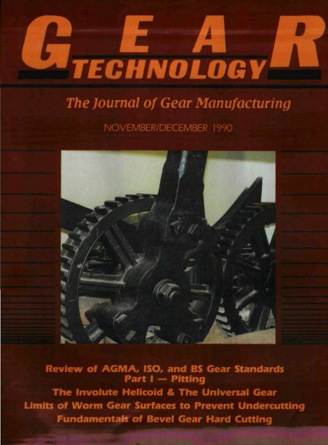
'Sun and Planet" mechanism develop.ed<br />
by James Watt to modify his steam<br />
eng<strong>in</strong>e to achieve rotary motion. In this<br />
system a cog wheel is attached' to <strong>the</strong><br />
connect<strong>in</strong>g rod ,and <strong>the</strong>n married to<br />
ano<strong>the</strong>r, usually smaller, cogwheel<br />
jo<strong>in</strong>ed to a flywheel. The mach<strong>in</strong>e<br />
shown was manufactured around 1787<br />
by Boulton & Watt. Itis at <strong>the</strong> Science<br />
Museum <strong>in</strong> Ed<strong>in</strong>burgh:. Scotland'. Our<br />
thanks to Mr. Richard' E Beale of<br />
Brisbane, Australia, for use of <strong>the</strong><br />
photos and <strong>in</strong><strong>format</strong>ion Or! this early<br />
steam eng<strong>in</strong>e.
The Journal 01Gear Manufactur<strong>in</strong>g<br />
CONTENTS<br />
FEATURES<br />
.A .REVIEW OF A:CNA, ISO, AND BS GEAR STANDAR~S •<br />
.P'ART 1 - PITTINC<br />
Doug Wall:on, YUloIIen Shl, Stan Taylor,<br />
University of B<strong>in</strong>n<strong>in</strong>gnam, Birm<strong>in</strong>gham. England<br />
10<br />
THE INVOLUTE HEUOOm AND THE UNIVERSAL GEAR<br />
Leonard J. Smith. Inv<strong>in</strong>cible 'Gear Co., Livonia, M]<br />
18<br />
UMITATION OF WORM AND' WORM CEAR SURFA:CES<br />
TO AVOID UNDERCUITING •••<br />
Vadim Kill, Purdue University, Hammond, IN<br />
30<br />
ED.lTORIAL 7<br />
VIEWPOINT 9<br />
BACK, TO BAJiICS • " '.<br />
,F1JNDAMENTALS OF BEVEL 'GEAR HARD CUTnNG<br />
Yogi, Sharma. Philadelphia Gear Co., K<strong>in</strong>g of Prussia. PA<br />
36<br />
CLASS[FJEDS 46<br />
<strong>November</strong>J<strong>December</strong>, <strong>1990</strong>_' V_o_I._7_, _N_o_. _6<br />
IN'ovemoer/Decem'ber 199Qi 3
Know<strong>in</strong>g<br />
it's Ground<br />
on a<br />
••<br />
BHS-HOFLER ...<br />
Unsurpassed <strong>in</strong> quality and speed<br />
- with capability to gr<strong>in</strong>d tooth<br />
modifications required for today's<br />
and tomorrow's needs.<br />
In a world of ever grow<strong>in</strong>g competition<br />
and demand for Quality, only<br />
<strong>the</strong> best will survive. Therefore<br />
modernize your gear production<br />
now where you need it most of all<br />
- <strong>in</strong> <strong>the</strong> gear gr<strong>in</strong>d<strong>in</strong>g room.<br />
BHS-HOFLER offers gear gr<strong>in</strong>d<strong>in</strong>g<br />
mach<strong>in</strong>es <strong>in</strong> 14 sizes for gears<br />
from 1" to 160" <strong>in</strong> diameter -<br />
manual- or CNC-technology.<br />
- For <strong>the</strong> first time ever:<br />
precision pallet load<strong>in</strong>g system.<br />
- Newly developed NC-dressable<br />
gr<strong>in</strong>d<strong>in</strong>g wheels.<br />
Call or write<br />
for more <strong>in</strong><strong>format</strong>ion:<br />
BHS-HOFLER CORP.<br />
P. O.Box 127<br />
Sky Manor Road<br />
Pittstown, NJ 08867<br />
j}fj!J<br />
147<br />
.. II<br />
Telephone: 908-996-6922<br />
Teletax; 908-996-6977<br />
Telex: 380576<br />
* ..• A reference list with more than 500 satisfied<br />
customers world-wide is available for <strong>the</strong><br />
ask<strong>in</strong>g who's who <strong>in</strong> <strong>the</strong> gear <strong>in</strong>dustry.<br />
CIRClE<br />
A-7 ON READER REPLYCARD
~BS;lhiliujil<br />
The IKashifuji KN 1150CNC<br />
Gear Hobber. High aocuracy<br />
assured through Irigidconstruction.<br />
Full 5 axis eNe controls plus<br />
hob rotation. Exce'ls over a wide<br />
range ,of high speedl hobb<strong>in</strong>g<br />
applications. Small foot Ipr<strong>in</strong>t.<br />
Easy and fast changeover<br />
accommodates vary<strong>in</strong>gllproduction lots.<br />
Handl'es gear sizesfrom 3f4" to40~<br />
High production capacity<br />
with fast auto loaders ..<br />
Kashifuji KN·150eNe Gear Hobbers.<br />
Contad. Kashifuil Product Manager,<br />
Midwest Branch,<br />
Cosa Corporation<br />
1,680 S. Uvernois,<br />
IRochester" M148063<br />
Tel. 313--652·7404<br />
Fax. 313·652-1450:.<br />
COSACORPORATION"<br />
MACHINETOOLDIVISION<br />
17 P,hilips Pal'lkway, Montvale" NJ 07645 Tel. 2011-3911-0700 Fax. 2011-391-4261<br />
C'IRCLE A~e ON IREADER IREPlY CARD
. . _, f' actU r<strong>in</strong>g<br />
S'Plen-<br />
. ala, nU<br />
- p~\&\QI\. • G- e'3' r 'IVI<br />
"e.t.\-t '10' , '<br />
TOtal QUallY .<br />
- - rn. 'Start<br />
IFro ,-<br />
Part blank and<br />
gear cutt<strong>in</strong>g tools,<br />
play .cl'hical lroles ill<br />
'q,lJality contnll.<br />
,oller optional soltware<br />
packages fur <strong>in</strong>spect<strong>in</strong>g<br />
gear blanks for<br />
circular geometry and g,eer<br />
cutt<strong>in</strong>g tools, such as hobs,<br />
shaperlshaver cutters,<br />
and broaches.<br />
Gear Test<strong>in</strong>g us<strong>in</strong>g Gener:aUve Metrology techniques,<br />
is enhanced by computerized autemallon<br />
andanalys[s. Ti'ue <strong>in</strong>dex, lead,<br />
and <strong>in</strong>volute test<strong>in</strong>g are performed<br />
Index<br />
Process control' 'can be<br />
implemented by analyz<strong>in</strong>g<br />
data collected<br />
l<strong>in</strong> gear test<strong>in</strong>g., We<br />
offer SPC software,<br />
'to evaluate x-bar, R.<br />
histogram, and<br />
tooth surface<br />
topological<br />
studles,<br />
31n2-4ac 'Gear A,nalyzer Is,<br />
one of a family of our gear<br />
and 'gearClfttlng tool! analyzers.<br />
For a free'full·color brochure<br />
describ<strong>in</strong>g our Gear analyzers,<br />
write or call MI& M IPrecision<br />
Systems, 300 Progress Rd.,<br />
Wesl Carrollton, OH 45449\<br />
513f859cS273,fAX 5131859-4452.<br />
CIRCI.!E A.!9 ON<br />
REAOE.R REPLY CAiRO<br />
M&M PAsc,s"aN<br />
_SYSTEMS<br />
AN ACME-CLEVELAND<br />
COMPANY
- PART IIII<br />
Beg<strong>in</strong>n<strong>in</strong>g with our ne.xt issue', som.e of.<strong>the</strong> pr.omised changes <strong>in</strong> fo.rmat f.or Gear<br />
Technology will beg<strong>in</strong> show<strong>in</strong>g up <strong>in</strong> <strong>the</strong>se pages. As part of our commitment to pro-<br />
- vide you with important <strong>in</strong><strong>format</strong>ion about <strong>the</strong> gear and gear products <strong>in</strong>dustry,<br />
weare expand<strong>in</strong>g our coverage. In addition to cont<strong>in</strong>u<strong>in</strong>g to publish some af<strong>the</strong> best results<br />
,ofgear research and development throughout <strong>the</strong> world, we will be add<strong>in</strong>g special columns<br />
cover<strong>in</strong>g vital aspects of <strong>the</strong> gear<strong>in</strong>g bus<strong>in</strong>ess.<br />
In our Shop Floorcolumn, several well-known gear<strong>in</strong>g professionals will discuss practical<br />
design and manufactur<strong>in</strong>g problems that appear <strong>in</strong> <strong>the</strong> work place. We <strong>in</strong>vite you to<br />
submit your questions to this panel of experts.<br />
Management Maners will cover some of <strong>the</strong> challenges of runn<strong>in</strong>g a gear design or<br />
manufacturi ng busl n ss<strong>in</strong> t he 90s. We willi cover such matters asdo<strong>in</strong>g bus<strong>in</strong>ess overseas,<br />
tra<strong>in</strong><strong>in</strong>g, employee problems, product liability, market<strong>in</strong>g for your company, and o<strong>the</strong>r<br />
items of concern to gear shops, both large and small.<br />
Along with <strong>the</strong>se additions to our<br />
editorial l<strong>in</strong>e-up, wewilll conl<strong>in</strong>ueto provide<br />
several art ides on gear design,<br />
manufactur<strong>in</strong>g, and research <strong>in</strong> every<br />
issue. Thls is one part of<strong>the</strong> magaz<strong>in</strong>e that<br />
will not change. While we are undergo<strong>in</strong>g<br />
a facelift, we have not lost sight of <strong>the</strong> fact<br />
that provid<strong>in</strong>g <strong>the</strong> latest <strong>in</strong><strong>format</strong>ion about<br />
gear rnanufacturtng, research, and development<br />
is our primary goal<br />
Along with <strong>the</strong>se editorial improvem<br />
nts, we shan be mak<strong>in</strong>g some<br />
cosmetic changes to ,Gear 7:echnology.<br />
Look for some new 'type faces, headl<strong>in</strong>e<br />
styles, and design elements to appear<br />
beg<strong>in</strong>n<strong>in</strong>g with next issue. Our goal with<br />
<strong>the</strong>se changes is to make <strong>the</strong> magaz<strong>in</strong>e<br />
more contemporary, more readable, and<br />
more useful to our readers.<br />
Perhaps <strong>the</strong> most readily apparent<br />
change 1.0 Gear Technology will be on<br />
our cover. W:ith some regret, we have<br />
reached <strong>the</strong> end ofour seriesof gear draw<strong>in</strong>gs<br />
by Leonardod'a V<strong>in</strong>ci. In <strong>the</strong> course or<br />
nearly seven years of publish<strong>in</strong>g, we have<br />
used most of <strong>the</strong> artist's gear-related<br />
draw<strong>in</strong>gs, and commission<strong>in</strong>g new ones is. beyond <strong>the</strong> power of our editorial and art staff.<br />
Instead, we will be featunngfour-color art on our covers. If you or youlr company have<br />
photos of gea rs, gears <strong>in</strong> motion, or gear cutti ng that you! h<strong>in</strong>k would rnakea good cover<br />
for Gear Technology, please send <strong>the</strong>m to our art department for consideration. We will<br />
credit you or vour company as <strong>the</strong> source, and <strong>the</strong> artwork wil!1be returned to you after<br />
<strong>the</strong> magaz<strong>in</strong>e is pr<strong>in</strong>ted.<br />
Our goal <strong>in</strong>execut<strong>in</strong>g <strong>the</strong>se changes to Gear r:echnologyis to keep up with <strong>the</strong> chang<strong>in</strong>g<br />
needs and <strong>in</strong>terests of you, om readers. As you strive to rema<strong>in</strong> competitive and keep<br />
up with <strong>the</strong> chang<strong>in</strong>g bus<strong>in</strong>ess climate, we ~-<br />
want to keep <strong>in</strong> step with you and con- ~ , . ..<br />
~~~r::of~~ :el~~~~~~r::i~s:~r' ;~f:~~:~e .• -~. -- . -~ -<br />
Michael Goldste<strong>in</strong>,<br />
IEditor/Publish<br />
IT'S YOUR MOVE<br />
GIEAR TECHNOLOGY always<br />
wants 10 be responsive to its<br />
readers. Please send us your<br />
reactions to th changes <strong>in</strong> our<br />
magaz<strong>in</strong>e. If you have ideas for<br />
additional or different columns,<br />
cover art, quesuons for our columnists,<br />
or just would like <strong>the</strong><br />
opportunity to respond to<br />
someth<strong>in</strong>g you've r ad <strong>in</strong> our<br />
pages, pleas let us know. A<br />
phone call or I tter to our<br />
ed itorial offices is always<br />
welcome.<br />
We also cont<strong>in</strong>ue to rema<strong>in</strong> on<br />
<strong>the</strong> lookout (or articles on all<br />
aspens or gear manufacture and<br />
design. These articles rema<strong>in</strong> rhe<br />
heart of our magaz<strong>in</strong>e. PI ase<br />
consider shar<strong>in</strong>g any article you<br />
have writ! n with us. Call or<br />
write for a copy or our editorial<br />
guidel<strong>in</strong> s.<br />
<strong>November</strong>jDecem'berl,990 7
Great American Geannakers<br />
deserve World Class f<strong>in</strong>ish<strong>in</strong>g<br />
equipment too!<br />
That's why we feature<br />
CIMA KANZAKI 'Gear Shavers.<br />
MODEL 'GSF 400<br />
eNe,6<br />
Built tough to withstand rigorous gearmak<strong>in</strong>g<br />
conditions, C~MA KANZAKI comb<strong>in</strong>es heavy<br />
duty construction with ground and hardened<br />
slides for maximum system rigidity. The<br />
result. .. accuracy levels to ± .00004" on<br />
workpieces up to 18" O.D. Additional<br />
standard features like Vickers hydraulics, a<br />
Trahan central lubrication system and a 20<br />
gpm coolant system complete <strong>the</strong> ClMA<br />
KANZAKI gear shaver ... designed and built.<br />
to deliver years of trouble-free operation.<br />
Comb<strong>in</strong>ed with <strong>the</strong> 4, 5 or 6 axis CNC<br />
control of your choice, <strong>the</strong> CIMA KANZAKlI<br />
Gear f<strong>in</strong>ish<strong>in</strong>g system provides unparalleled<br />
operat<strong>in</strong>g flexibility, faster set-ups for greater<br />
productivity and an easy DNC <strong>in</strong>terface for<br />
improved management<strong>in</strong>fonnation.<br />
And .... CIMA KANZAKlI models can be equipped with<br />
semi- or tully-automatic tool changers and automated load/<br />
unload systems for <strong>in</strong> l<strong>in</strong>e (cell) applications.<br />
CIMA KANZAK~ is proud to serve Great American<br />
Gearmakers with equipment that REDUCES CYCLE<br />
TIMES, IMPROVES or MONITORS QUALITY and<br />
INCREASES SHOP PROFIT ABILITY. And, we support<br />
equipment with unparalleled spare parts & service<br />
capability ... if it's ever required.<br />
Ask our sales representative forfur<strong>the</strong>r details or contact<br />
CIMA-USA,lDivision of' GDPM Inc., 50] Southlake Blvd.,<br />
Richmond, VA 23236. Phone (804) 794-9764,<br />
FAX (804) 794-6187. Telex 6844252.<br />
Global Technology with a U.S..Base<br />
CIRCLE A-lOON<br />
READER REPLYCARD
VIEWPOINT<br />
THE LEADER IN<br />
GEAR<br />
DEBURRING<br />
Dear<br />
Editor:<br />
Yourartide on <strong>the</strong> ]TCs Report to <strong>the</strong> President on<br />
<strong>the</strong> condition of <strong>the</strong> U.S. gear <strong>in</strong>dustry (Sept.lOcL<br />
issue) was most <strong>in</strong>terest<strong>in</strong>g, I am wonder<strong>in</strong>g if <strong>the</strong><br />
total report neglected to mention that some of our<br />
Lnability to export gears is due to our reluctance to<br />
provide metric countries with <strong>the</strong> metric module-based<br />
gears that overseas customers demand,<br />
I also hope your readers are apprised of <strong>the</strong> fact<br />
that those <strong>in</strong>volved <strong>in</strong> furnish<strong>in</strong>g gears to <strong>the</strong> U. S.<br />
government as contractors will have to provide<br />
metric-dimensioned gears after 1992.<br />
S<strong>in</strong>cerely,<br />
Valerie Anto<strong>in</strong>e<br />
Executive Director<br />
U.S. Metric Association, Inc.<br />
EDITOR'S NOTE: The relevent portion of <strong>the</strong> Omnibus<br />
Trade and Competitiveness Act of 1988 reads as<br />
follows:<br />
"... It is <strong>the</strong>refore <strong>the</strong> declared policy of <strong>the</strong> United<br />
States {l)to designate <strong>the</strong> metric system of measurement<br />
as <strong>the</strong> preferred system of weights and measures<br />
for U.S. trade and commerce: (2) to require that each<br />
Federal. agency, by a date certa<strong>in</strong> and to <strong>the</strong> extent<br />
ecnomically feasible by <strong>the</strong> end, of <strong>the</strong> fiscal year 1992,<br />
use <strong>the</strong> metric system of measurement <strong>in</strong> its procurements"<br />
grants, and o<strong>the</strong>r bus<strong>in</strong>ess-related ,a.ctivilties,<br />
except to <strong>the</strong> extent that such use is impractical or is<br />
likely to cause significant <strong>in</strong>efficiences or loss of<br />
markets to U.S. firms ... "<br />
Readers should also note that <strong>in</strong> a july 30 letter to<br />
Secretary of Commerce Robert A. Mosbacher, NASA<br />
<strong>in</strong>formed <strong>the</strong> secretary that "Effective with <strong>the</strong> start of<br />
<strong>the</strong> new fiscal year, October 1, <strong>1990</strong>', aU Requests for<br />
Proposals for new NASA flight programs will require<br />
use of <strong>the</strong> metric system of measurement." A memo .<br />
dated July 20, <strong>1990</strong>, which sets NASA policy on<br />
metric conversion states: "Ongo<strong>in</strong>g programs may<br />
cont<strong>in</strong>ue use of <strong>the</strong> conventional <strong>in</strong>ch-pound system<br />
basel<strong>in</strong>e for hardware design, but must plan to accommodate<br />
<strong>the</strong> metric hardware that will result from this<br />
transition. "<br />
Letters for this column should be addressed to Letters<br />
to <strong>the</strong> Editor, GEAR TECHNOLOGY, P.Q. Box 1426,<br />
Elk Grove Vill'age, IL 60009. Letters sent to this column<br />
become .<strong>the</strong> property of GEAR TECHNOLOGY.<br />
Names wi1l be withheld upon request, however, no<br />
anonymous letters will' be published.<br />
"ZERO-SETUP'<br />
• Rad<strong>in</strong> Modell 24-Universal' gear chamfer<strong>in</strong>g/deburr<strong>in</strong>g<br />
mach<strong>in</strong>e - 2 models.<br />
'. Ehm<strong>in</strong>ates costly manual mach<strong>in</strong>e setup.<br />
• C.N.C. controlled - 8 or 10 axis.<br />
• Part program storage -1000 pip.<br />
• Program load<strong>in</strong>gl - M.D.I. or Disc.<br />
• S<strong>in</strong>gle or doubl'ehead mach<strong>in</strong>es.<br />
1817 - 18th Ave.<br />
Rockford. IlL 611104<br />
8115~39S~1010 IFAX.S15-398-11047<br />
DEALERS WELOOME!<br />
CIRCLE A-lION<br />
0,<br />
G~ GRINO FACLIlY· COMPlETE GEI
AGMA, ISO, and B,SGear Stan'dard's<br />
P,artI Pitt<strong>in</strong>g Resistance Rati,ngs<br />
Doug Walton, Yuwen Shi, Stan Taylor,<br />
Mechanical Eng<strong>in</strong>eer<strong>in</strong>g Department<br />
University of Birm<strong>in</strong>gham, Birm<strong>in</strong>gham, U.K.<br />
Summary:<br />
A study of AGMA 218, <strong>the</strong> draft ISO standard 6336, and<br />
5S 436: 1986 methods for rat<strong>in</strong>g gear tooth strength and surface<br />
durability for metallic spur and helical gears is<br />
presented. A comparison of <strong>the</strong> standards ma<strong>in</strong>ly focuses on<br />
fundamental formulae and <strong>in</strong>fluence factors, such as <strong>the</strong><br />
load distribution factor, geometry factor, and o<strong>the</strong>rs. No attempt<br />
is made to qualify or judge <strong>the</strong> standards o<strong>the</strong>r than<br />
to comment on <strong>the</strong> facilities or lack of <strong>the</strong>m <strong>in</strong> each standard<br />
reviewed. In Part I a comparison of pitt<strong>in</strong>g resistance rat<strong>in</strong>gs<br />
is made, and <strong>in</strong> <strong>the</strong> subsequent issue, Part IIwill deal with<br />
bend<strong>in</strong>g stress rat<strong>in</strong>gs and comparisons of designs.<br />
Introduction<br />
Standard spur and helical gears are usually designed to<br />
specific standards to meet <strong>the</strong> requirements of proportions,<br />
manufactur<strong>in</strong>g accuracy, and load rat<strong>in</strong>g. The load rat<strong>in</strong>g is<br />
<strong>the</strong> most important issue discussed <strong>in</strong> AGMA (American<br />
Gear Manufacturers Association), ISO (International Standards<br />
Organization), DIN Deutsche lndustrie Norrnen) and<br />
BSI (British Standards Institution) gear standards. The standards<br />
written by <strong>the</strong>se organizations are widely used for gear<br />
design throughout <strong>the</strong> worJd and also fonn <strong>the</strong> basis of<br />
"m<strong>in</strong>ority" gear standards. Ch<strong>in</strong>a, for example, issues a gear<br />
design standard based on ISO. European gear standards are<br />
now becom<strong>in</strong>g very similar. The new BS and <strong>the</strong> draft ISO<br />
standard share much <strong>in</strong> common with DIN. This paper considers<br />
BS 436:1986, <strong>the</strong> draft ISO standard 6336, and AGMA<br />
218.01. S<strong>in</strong>ce this review was written, AGMA <strong>in</strong>troduced<br />
AGMA.2001-B88, although this new standard is not considered<br />
here. However, <strong>the</strong> trend toward a universal standard<br />
cont<strong>in</strong>ues, with AGMA 2001 publish<strong>in</strong>g rat<strong>in</strong>g factors, some<br />
of which are similar to <strong>the</strong> draft ISO standard.<br />
This article is <strong>in</strong>tended for designers who will appreciate a<br />
review of this complex subject ..Many designers <strong>in</strong> <strong>the</strong> USA<br />
will still use AGMA 218 because <strong>the</strong>y are familiar with it, and<br />
will, we suspect, cont<strong>in</strong>ue to do so for some time ..(This situation<br />
also exists <strong>in</strong> <strong>the</strong> UK with respect to <strong>the</strong> old and new<br />
British Standards on gear rat<strong>in</strong>gs.) It will take <strong>the</strong> authors<br />
some time before <strong>the</strong>y have enough experience <strong>in</strong> <strong>the</strong> use of<br />
AGMA 2001 and have been able to validate it aga<strong>in</strong>st real<br />
designs and o<strong>the</strong>r rat<strong>in</strong>g standards. While <strong>the</strong>re are marked<br />
similarities between <strong>the</strong> old and new AGMA formulas for pitt<br />
0 Gear Technology<br />
t<strong>in</strong>g resistance and bend<strong>in</strong>g strength rat<strong>in</strong>gs, we have ma<strong>in</strong>ly<br />
excluded any reference to AGMA 2001.<br />
Although, <strong>the</strong>oretically, any standard will produce a gear<br />
pair which is satisfactory, it is no longer enough to accept any<br />
standard when o<strong>the</strong>r procedures might produce more competitive<br />
designs. On <strong>the</strong> o<strong>the</strong>r hand, if <strong>the</strong> design calls for<br />
special operat<strong>in</strong>g conditions, such as shock loads or flexible<br />
drives, it may be advantageous for <strong>the</strong> designer to address a<br />
standard which deals more closely with <strong>the</strong>se conditions, In<br />
addition, <strong>the</strong> customer may specify <strong>the</strong> code to be used. A<br />
work<strong>in</strong>g knowledge of more than one standard is desirable,<br />
particularly if <strong>the</strong> product is aimed at<strong>in</strong>ternational markets.<br />
An understand<strong>in</strong>g of <strong>the</strong> differences between gear standards<br />
is, <strong>the</strong>refore, important. It should be po<strong>in</strong>ted out, however,<br />
that <strong>in</strong> a review of gear standards it is impossible to cover<br />
every aspect of each code. ISO 6336 Parts 1 to 4, for example,<br />
conta<strong>in</strong> over 90 figures and over 20 tables.<br />
Standards for Spur and Helical Gears<br />
The old British Standard, BS 436:1940, (I} <strong>in</strong> use for nearly<br />
fifty years, was a revision of <strong>the</strong> orig<strong>in</strong>al Specification for<br />
Mach<strong>in</strong>e Cut Gears first issued <strong>in</strong> 1932. Dur<strong>in</strong>g its long existence,<br />
<strong>the</strong> rat<strong>in</strong>g method rema<strong>in</strong>ed <strong>the</strong> same with only m<strong>in</strong>or<br />
revisions. Though obsolescent, it is still used extensively<br />
throughout Brita<strong>in</strong> and elsewhere, ma<strong>in</strong>ly because it is easy<br />
to use. The standard rates gears on <strong>the</strong> basis of bend<strong>in</strong>g<br />
strength and contact stresses, which are referred to as wear<br />
(mean<strong>in</strong>g non-abrasive wear). The tooth root bend<strong>in</strong>g<br />
strength is based on <strong>the</strong> Lewis equation, (2) consider<strong>in</strong>g both<br />
tangential and radial loads. The effect of stress concentrations<br />
at <strong>the</strong> root is not taken <strong>in</strong>to account directly, but allowances<br />
are made <strong>in</strong> <strong>the</strong> use of <strong>the</strong> allowable bend<strong>in</strong>g strength of <strong>the</strong><br />
gear material, values for which are supplied <strong>in</strong> <strong>the</strong> standard.<br />
The bend<strong>in</strong>g strength is also factored for runn<strong>in</strong>g speed and<br />
life. Contact stresses are based on a modified Hertz equation<br />
with allowances for speed, runn<strong>in</strong>g time, and geometry. The<br />
latter item is taken <strong>in</strong>to consideration by a zone factor, which<br />
accounts for <strong>the</strong> <strong>in</strong>fluence on <strong>the</strong> Hertzian stress of tooth flank<br />
curvature at <strong>the</strong> pitch po<strong>in</strong>t, and converts <strong>the</strong> tangential load<br />
to a normal force. No serious attempt was made to keep this<br />
standard up to date on newer gear materials and processes to<br />
predict <strong>the</strong> higher performances be<strong>in</strong>g achieved <strong>in</strong> practice.<br />
Ano<strong>the</strong>r serious deficiency is that no account was made for<br />
surface f<strong>in</strong>ish or uneven load distribution.
BS 436:1940<br />
d Pitch diameters of p<strong>in</strong>ion and wheel<br />
Ee Equivalent Young's modulus<br />
F Face width<br />
k Constant <strong>in</strong> Hertz contact stress formula<br />
K Pitch Eactor<br />
n, N P<strong>in</strong>ion and wheel runn<strong>in</strong>g speed<br />
P DiametraJ pitch<br />
R Gear ratio<br />
Rr Relative radius of curvature<br />
s Maximum contact stress set <strong>in</strong> <strong>the</strong> surface layers of<br />
<strong>the</strong> gear cyl<strong>in</strong>ders<br />
Sc Surface stress factor<br />
T Number of teeth on wheel<br />
Xc Speed factor for contact. stress<br />
Z Zone factor<br />
at Transverse pressure angle at reference cyl<strong>in</strong>der<br />
atw Transverse pressure angle at pitch cyl<strong>in</strong>der<br />
I3b Base helical angle<br />
AGMA218.01<br />
C.. Application faetar for pitt<strong>in</strong>g resistance<br />
C c Curvature factor at pitch l<strong>in</strong>e<br />
CI Surface condition factor<br />
C H Hardness ratio factor<br />
CL life factor for pitt<strong>in</strong>g resistance<br />
em Load distribution factor for pitt<strong>in</strong>g resistance<br />
NOMENCLATURE<br />
c;, Elastic coefficient<br />
C R Reliability factor for pitt<strong>in</strong>g resistance<br />
C, Size factor for pitt<strong>in</strong>g resistance<br />
CT Temperature factor for pitt<strong>in</strong>g resistance<br />
c,.. Dynamic factor for pitt<strong>in</strong>g resistance<br />
Cx Contact height factor<br />
---<br />
Smith(3) described B5 436 as "an. average experience<br />
method, wherebygear manufacturers and users collaborate<br />
to provide extremely empirical rules of thumb based on<br />
operat<strong>in</strong>g experience. Permissible loads are specified for<br />
'typical' manufacturir1g accuracies of a given class with<br />
'typical.' load<strong>in</strong>g cycles and corrections for speed, etc."<br />
Although <strong>the</strong> standard did not take <strong>in</strong>to account factors<br />
known to <strong>in</strong>fluence bend<strong>in</strong>g and contact stresses, such as application<br />
conditions (i.e., <strong>the</strong> load fluctuations caused by external<br />
sources), system dynamics and gear accuracy and <strong>the</strong><br />
benefits of surface harden<strong>in</strong>g, <strong>the</strong> standard served its users<br />
well.<br />
The orig<strong>in</strong>al AGMA standard was issued <strong>in</strong>1926, and <strong>the</strong><br />
first draft of AGMA 218.01,(4) used. <strong>in</strong> this review, was<br />
drafted <strong>in</strong> 1973 and approved for publication <strong>in</strong> 1982. AGMA<br />
218 also rates gearson <strong>the</strong> basis of bend<strong>in</strong>g strength and surface<br />
contact stresses, (referred to as surface durability or pitt<strong>in</strong>g)<br />
but also <strong>in</strong>troduces a. number of o<strong>the</strong>r factors <strong>in</strong> <strong>the</strong><br />
rat<strong>in</strong>g equations. For example, <strong>in</strong>fluence factors are used to<br />
take <strong>in</strong>to account load distribution across <strong>the</strong> face width,<br />
quality of<strong>the</strong>bcansmission drive, and transmission accuracy<br />
relat<strong>in</strong>g to manufacture, Considerable knowledge and judgment<br />
is required to determ<strong>in</strong>e values for <strong>the</strong>se factors.<br />
Compared to <strong>the</strong> old British Standard, AGMA 218 is considerably<br />
mare comprehensive. Rat<strong>in</strong>gs for pitt<strong>in</strong>g resistance<br />
are based on '<strong>the</strong> Hertzian equation for contact pressure betw'een<br />
curved surfaces, which is modified for <strong>the</strong> ,effectof load<br />
shar<strong>in</strong>g between adjacent teeth. The Lewis equation has been<br />
madified to account far ,effects, such as stress concentrations,<br />
at <strong>the</strong> tooth root, compressive stresses result<strong>in</strong>g from <strong>the</strong><br />
Cv, Helical overlap factor<br />
d Operat<strong>in</strong>g pitch diameter of p<strong>in</strong>ion<br />
F Net facewidth of <strong>the</strong> narrowest number<br />
I Geometry factor for pitt<strong>in</strong>g resistance<br />
mN Load shar<strong>in</strong>g ratio<br />
np P<strong>in</strong>ion runn<strong>in</strong>g speed<br />
P 1I Diarnetral pitch<br />
Sac Allowable contact stress number<br />
85436: 1986 and ISO/DIS 6336<br />
b Face width<br />
d 1 Reference diameter of p<strong>in</strong>ion<br />
KA Application factor<br />
KHa Transverse load factor for contact stress<br />
K H ,9 Face load factor for contact stress<br />
Kv Dynamic factor<br />
n1 P<strong>in</strong>ion runn<strong>in</strong>g speed<br />
SHmm M<strong>in</strong>imum demanded safety factor on contact stress<br />
ZM (BS only material quality factor for contact stress)<br />
ZN life factor for contact stress<br />
Zx Size factor for contact stress<br />
ZE Elasticity factor for contact stress<br />
ZH Zone factor for contact stress<br />
ZL,ZR,ZV Lubricant <strong>in</strong>fluence. roughness, and speed factor for<br />
pitt<strong>in</strong>g<br />
Zw Work-harden<strong>in</strong>g factor for contact stress<br />
Z, Contact ratio factor for contact stress<br />
Zfj Helix angle factor<br />
at Transverse pressure angle at reference cyl<strong>in</strong>der<br />
atw Transverse pressure angle at pitch cyl<strong>in</strong>der<br />
(3b Base helix angle<br />
'O'Hlim Basic endurance limit for contact stress<br />
uHP Permissible contact stress<br />
radial. component of <strong>the</strong> gear load, load distribution due to<br />
misalignment between mesh<strong>in</strong>g teeth, andload shar<strong>in</strong>g. The<br />
'Critical bend<strong>in</strong>g stress is assumed to occur at <strong>the</strong> tooth fillet<br />
but, as <strong>in</strong> <strong>the</strong> old British Standard, <strong>the</strong> effect of blank<br />
geometry (e.g., rimand web size and how <strong>the</strong> relative size of<br />
<strong>the</strong>se effects stresses at <strong>the</strong>tooth root) is not considered.<br />
The 150 standard, ISO 6336,
scuff<strong>in</strong>g ..The basic equations are modified by apply<strong>in</strong>g. <strong>in</strong>fluence<br />
factors as <strong>in</strong> A:GMA. These procedures demand a<br />
realistic appraisal of all <strong>in</strong>fluence factors, particularly those<br />
for <strong>the</strong> allowable stress, <strong>the</strong> probability of failure, and <strong>the</strong> appropriate<br />
safety factor. ISO also offers three different<br />
methods for determ<strong>in</strong><strong>in</strong>g bend<strong>in</strong>g and contact stresses and<br />
<strong>the</strong>ir <strong>in</strong>fluence factors, depend<strong>in</strong>g on <strong>the</strong> application and accuracy<br />
required. S<strong>in</strong>ce <strong>the</strong> latest German standard, DIN 3990:<br />
1987, (6) is substantially similar to ISO 6336,. a detailed discussionof<br />
DIN is excluded.<br />
The new British standard, BS 436:1986,(7) is similar to<br />
ISO / DIS 6336 and is a complete revision of <strong>the</strong> old standard.<br />
It is, however, much more user friendly than [SO. Like <strong>the</strong><br />
o<strong>the</strong>r standards, <strong>the</strong> new British standard uses modified Lewis<br />
and Hertz equations, us<strong>in</strong>g correction factors, such as <strong>the</strong><br />
dynamic factor to account for load fluctuations aris<strong>in</strong>g from<br />
manufactur<strong>in</strong>g errors, and a load distribution factor to take<br />
<strong>in</strong>to account <strong>the</strong> <strong>in</strong>crease <strong>in</strong> local load due to non-uniform<br />
load<strong>in</strong>g aris<strong>in</strong>g from conditions such as shaft stiffness and, <strong>in</strong><br />
<strong>the</strong> case of helical gears, helix error. The correction factors are<br />
<strong>the</strong> same or are similar to those used. by ISO. Geometry factors<br />
<strong>in</strong> <strong>the</strong> new BS 436 are similar to those <strong>in</strong> ISO (method B)<br />
willIe o<strong>the</strong>r methods <strong>in</strong> ISO use different approaches for<br />
geometry factors ..The new British standard, however, draws<br />
on a considerable amount of previously published research<br />
and uses additional parameters, like materia] quality factors,<br />
not allowed for by ISO or AGMA. This standard does not<br />
work on "typical" figures for each rat<strong>in</strong>g factor as <strong>in</strong> <strong>the</strong> old<br />
standard, but uses researched data to predict load <strong>in</strong>creases<br />
caused by deflections, alignment tolerances, and helix<br />
modifications. Throughout this review, <strong>the</strong> term.BS refers to<br />
<strong>the</strong> new standard, except where stated.<br />
In <strong>the</strong> stress analysis procedures of BSand ]50, bend<strong>in</strong>g<br />
and contact stresses are classified <strong>in</strong>to three groups: 1)<br />
Nom<strong>in</strong>al or basic stresses, which
COMPLE,TEWITIH ,A,LLlE,NBRADLlE,V PLe<br />
C'ONTRO!l ,A,ND CRT O'PERATOR IINTEIRFACE<br />
Ea'Syto use canned cycles <strong>in</strong>olude: Variable Hob Speeds"<br />
Variable axial a'nd radial feed rates~ Hob, shift <strong>in</strong>ct:ements<br />
and ft:equency. Dwell times, 'S<strong>in</strong>gle, dou.ble and r:adiaJ'cut<br />
cycles, Axial cycle work<strong>in</strong>g' limits, - and muoh' more!<br />
Specific p,arameters are f<strong>in</strong>,e tuned throug,h simple' M.D.!. <strong>in</strong>put.<br />
Call or write today..<br />
FAX. 203 :271110487 BOX 400' W. JOHNSON AVE. CHESHIRE, CT. 06410<br />
CIRCLE A-13 ONI READER REPLY CARD
mation is required and some, like generat<strong>in</strong>g <strong>the</strong> tooth layout<br />
to give <strong>the</strong> necessary geometry data, may be difficult to<br />
obta<strong>in</strong>.<br />
3) Each standard has its own def<strong>in</strong>itions for <strong>the</strong> <strong>in</strong>fluence<br />
factors, but factors bear<strong>in</strong>g <strong>the</strong> same names do not necessarily<br />
have <strong>the</strong> same effects. This makes direct comparisons of <strong>in</strong>fluence<br />
factors difficult. For example, although AGMA and<br />
ISO both <strong>in</strong>troduce a service factor, <strong>the</strong> values cannot be<br />
compared directly.<br />
The terms used <strong>in</strong> each standwdare listed <strong>in</strong> <strong>the</strong><br />
nomenclature .<br />
The power rat<strong>in</strong>g for contact stressesgiven by BS436: 1940<br />
XcScZFNT<br />
126000KP<br />
Equation 1can be rewritten as<br />
____ n Fd2 Rr_Xe<br />
0.8 s2<br />
126000 d k Ee<br />
For AGMA 218.01 <strong>the</strong> transmissible power based on pitt<strong>in</strong>g is<br />
n Fd<br />
e 2<br />
..<br />
126000<br />
The as 436:1986 power rat<strong>in</strong>g is<br />
b d 1<br />
2 n1 u 1<br />
126000 u+1 ZH 2 Z~<br />
and for ISO lOIS 6336 <strong>the</strong> power is<br />
bdlnl U 1<br />
126000 u+I zi Z; z3<br />
where<br />
UHP = (O"H1irn ZN). z, ZR Zv Zw z, (7)<br />
SHm<strong>in</strong><br />
From Equations 2-7 it may be seen that for a given gear<br />
ratio <strong>the</strong> transmissible power is proportional to <strong>the</strong> square<br />
of <strong>the</strong> p<strong>in</strong>ion pitch circle diameter and permissible contact<br />
stresses. Therefore, to <strong>in</strong>crease gear power capacity <strong>in</strong> terms<br />
of surface durabilty, it is more effective to <strong>in</strong>crease <strong>the</strong> p<strong>in</strong>ion<br />
peD or permissible surface stresses than to <strong>in</strong>crease <strong>the</strong> gear<br />
pair facewidth.<br />
The pitt<strong>in</strong>g resistance related factors above may be<br />
grouped <strong>in</strong>to common and non-common factors. Common<br />
factors are those which have <strong>the</strong> same mean<strong>in</strong>gs <strong>in</strong> all <strong>the</strong><br />
standards, (not all <strong>the</strong>se factors appear <strong>in</strong> <strong>the</strong> standards) and<br />
<strong>the</strong>i:r values can becompared directly. For example, <strong>the</strong><br />
dynamic factor whichallows for <strong>in</strong>ternally generated gear<br />
tooth loads <strong>in</strong>duced by non-conjugate mesh<strong>in</strong>g action of <strong>the</strong><br />
gear teeth, appears <strong>in</strong> all <strong>the</strong> standardsexcept <strong>the</strong> old BS, and<br />
values can be compared directly. Non-common factors,<br />
such as <strong>the</strong> geometry factor,are those which are only<br />
equivalent to each o<strong>the</strong>r <strong>in</strong> <strong>the</strong> sense of hav<strong>in</strong>g <strong>the</strong> same eEl'4<br />
Gear feehnology<br />
1<br />
1<br />
(1)<br />
(2)<br />
(3)<br />
fects on <strong>the</strong> rat<strong>in</strong>g results, although specific values cannot<br />
be compared.<br />
Table 1classifies all <strong>the</strong> contact stress <strong>in</strong>fluence factors <strong>in</strong>to<br />
ei<strong>the</strong>r common or non-common groups where it can be seen<br />
that <strong>the</strong> old British Standard had few parameters for comparison<br />
with o<strong>the</strong>r standards. The similarity between BSand<br />
ISO isalso apparent. A comparison between <strong>the</strong> <strong>in</strong>fl'uence<br />
factors given <strong>in</strong>each standard is made <strong>in</strong> <strong>the</strong> follow<strong>in</strong>g<br />
paragraphs.<br />
1) Application factors. An application factor is used <strong>in</strong><br />
AGMA, ISO,. and BS to evaluate external <strong>in</strong>fluences tend<strong>in</strong>g<br />
to apply a greater load to <strong>the</strong> gear teeth than that based on<br />
steady runn<strong>in</strong>g conditions. Typical external <strong>in</strong>fluences are<br />
<strong>the</strong> drive characteristics (e..g., smoothness and load fluctuations)<br />
of <strong>the</strong> prime mover and of <strong>the</strong> driven mach<strong>in</strong>e ..Values<br />
suggested <strong>in</strong> ISO correspond to those for <strong>the</strong> overload factor<br />
<strong>in</strong> AGMA 215. While no data appears <strong>in</strong>.AGMA 218,<br />
<strong>the</strong>se factors may be found <strong>in</strong> related AGMA application<br />
standards. BS gives more detailed conditions than ISO,<br />
although values are similar.<br />
2) Dynamic factors. As discussed above, <strong>the</strong> application<br />
factor is used to handle dynamic loads unrelated to tooth accuracy.<br />
The effect of dynamic load related gear tooth accuracy<br />
is <strong>the</strong>n evaluated by <strong>the</strong> Inclusion of a dynamic factor<br />
which accounts for effects ·of gear set mass elastic effects<br />
and transmission errors. AGMA modified <strong>the</strong> experimental<br />
work of Wellauer(14l to obta<strong>in</strong> dynamic factors as a function<br />
of transmission error. These accuracy levels can under certa<strong>in</strong><br />
manufactur<strong>in</strong>g conditions be <strong>the</strong> same as <strong>the</strong> gear quality<br />
numbers given <strong>in</strong> AGMA 390. (15)<br />
ISO dynamic factors are based on Buck<strong>in</strong>gham's <strong>in</strong>crementalload<br />
method U6J and work by Weber and Banaschek.(l7J<br />
ISO (analytical) method B presents a calculation procedure<br />
for <strong>the</strong> ma<strong>in</strong> resonance speed and divides <strong>the</strong> runn<strong>in</strong>g speed<br />
<strong>in</strong>to three sectors. The dynamic factor corresponds to each<br />
of <strong>the</strong>se speed sectors and may help designers to adjust <strong>the</strong><br />
operat<strong>in</strong>g speed or alter <strong>the</strong> design to avoid critical speeds ..<br />
ISO method C is only applicable to gears with accuracy<br />
numbers of 3 to 10 and cannot be used for gears operat<strong>in</strong>g at<br />
or near <strong>the</strong> ma<strong>in</strong>. resonance speed. The dynamic factor <strong>in</strong> <strong>the</strong><br />
BS is very dose to [SO method C. In <strong>the</strong> old BS, dynamic ef-<br />
£ects were not considered. The speed factor used <strong>in</strong> <strong>the</strong> old BS<br />
is not to be confused with dynamic loads, but was <strong>in</strong>tended<br />
to allow f·or load reversals and <strong>the</strong>ir eHed on fatigue dur<strong>in</strong>g<br />
<strong>the</strong> life of <strong>the</strong> gear.<br />
It has been customary fer AGMA to put <strong>the</strong> dynamic factor<br />
<strong>in</strong> <strong>the</strong> denom<strong>in</strong>ator of <strong>the</strong> rat<strong>in</strong>g formula, whereas ISO<br />
and BS apply it to <strong>the</strong> numerator. Never<strong>the</strong>less, <strong>the</strong> dynamic<br />
factor is def<strong>in</strong>ed as a multiplier of <strong>the</strong> transmitted load <strong>in</strong> all<br />
<strong>the</strong> standards, although some believe that <strong>the</strong> effect should<br />
be additive. (18)<br />
3) Load distribution factors. A load distribution factor is<br />
used <strong>in</strong> <strong>the</strong> rat<strong>in</strong>g equations to reflect <strong>the</strong> non-uniform load<br />
distribution along <strong>the</strong> contact l<strong>in</strong>es caused by deflections,<br />
alignment, and helix modifications (<strong>in</strong>clud<strong>in</strong>g crown<strong>in</strong>g and<br />
end relief), and profile and pitch deviations ..The evaluation<br />
procedure for this factor is ra<strong>the</strong>r complex, siace many<br />
variables are <strong>in</strong>volved, and some of <strong>the</strong>m, such as <strong>the</strong> component<br />
of <strong>the</strong> gear system alignment and manufactur<strong>in</strong>g<br />
errors, are difficult to determ<strong>in</strong>e.
TABLE 1 COMPARISON OF PITTING RESISTANCE INFLUENCE FACTORS<br />
BS436:1940 AGMA21B BS 436:1986 150/0[56336<br />
Geometry<br />
R~·8<br />
u 1 u 1<br />
I<br />
Factors- - -- --- --<br />
d u + 1 Z"; Z2 u+1 Z].Z2 Z2<br />
• H , Ii<br />
Elasticity<br />
(k~}O.5 C p ZE ZE<br />
Factors"<br />
Size<br />
Factors"<br />
1 1<br />
- C s - -<br />
Z2~<br />
Z;<br />
Lubrication 1 ]<br />
Film - C~·5C T ZLZVZR ZtZVZR<br />
Factors"<br />
Application<br />
Factors]<br />
Dynamic<br />
Factors]<br />
- C a KA KA<br />
1 1<br />
- Cv<br />
- -<br />
Kv<br />
Ky<br />
Load 1 1<br />
Distribution<br />
Factorst<br />
- Cm<br />
KHaKHIl'<br />
KH ..KHIl<br />
Work<br />
Harden<strong>in</strong>g - CH Zw Zw<br />
Eactors]<br />
Life<br />
Factorst<br />
Reliability<br />
Factors]<br />
-<br />
CL ZN ZN<br />
- CR SHlim SHm<strong>in</strong><br />
Material<br />
Quality - - ZM -<br />
Factor]<br />
Speed<br />
Factor]<br />
t denotes common and .. non-common factors<br />
'""--<br />
In AGMA <strong>the</strong> load distributi.on factor is <strong>the</strong> product of <strong>the</strong><br />
face and 'transverse load distnbution ~fa.ctors.The face or<br />
Iongituil<strong>in</strong>aJ (as described <strong>in</strong> <strong>the</strong> ISO and BS) load distribution<br />
factor accounts for <strong>the</strong> non-uniform load across <strong>the</strong> face<br />
of <strong>the</strong> gear. while <strong>the</strong> transverse load factor reflects <strong>the</strong> effect<br />
of non-uniform distribution of load down <strong>the</strong> tooth flank due<br />
to profile, pitch deviations. and tooth modifications.<br />
Although AGlv1Auses this factor to allow for <strong>the</strong> effect of <strong>the</strong><br />
non-unilorm distribution of load among <strong>the</strong> teeth.which share<br />
<strong>the</strong> t.otalload, no specific wonnanon is given <strong>in</strong> <strong>the</strong> standard.<br />
The AGMA standard assumes that if <strong>the</strong> gears are accurately<br />
manufactured, <strong>the</strong> value of <strong>the</strong> transverse load distribution<br />
factor can be 'taken as unity. AGMA provides both empirical<br />
and analytical methods to.determ<strong>in</strong>e <strong>the</strong> face load distribution<br />
factor ..The empirical method is recommended for norma1,relatively<br />
stiff gear .a.ssemblies,and only a m<strong>in</strong>imum<br />
amount of <strong>in</strong><strong>format</strong>ion is required. The second method is<br />
based. on elastic and non-elastic lead mismatch and needs <strong>in</strong><strong>format</strong>ion<br />
about design. manufacture. and mount<strong>in</strong>g and is.<br />
<strong>the</strong>oretically, suitable tor any ge.ar design ..<br />
Xc - - -<br />
The ISO load distribution factor is also <strong>the</strong> product of <strong>the</strong><br />
transverseand longitud<strong>in</strong>a] load factors. Three differentappreaches<br />
have been made by ISO to detenn<strong>in</strong>e <strong>the</strong><br />
longitud<strong>in</strong>al load factor ..Method B is a f<strong>in</strong>al proof rat<strong>in</strong>g<br />
calculation method based on known manufactur<strong>in</strong>gerrors.<br />
Method C is a prelim<strong>in</strong>ary rat<strong>in</strong>g method and uses assumed<br />
values of manufactur<strong>in</strong>g errors with<strong>in</strong> limits of prescribed<br />
tolerances. Method 0 is even more simplified than method<br />
C. The transverse load factor isa function of longitud<strong>in</strong>al load<br />
factor, contact ratio, pitch tolerance, and mean load <strong>in</strong>tensity.<br />
Procedures for calculat<strong>in</strong>g <strong>the</strong> load distribution factors<br />
<strong>in</strong> ISO are <strong>the</strong> most complex and are still under revision . Load<br />
distribution factors <strong>in</strong> <strong>the</strong> BSemploy virtually <strong>the</strong> same procedure<br />
as method C <strong>in</strong> 150,. except for a diffef'ence <strong>in</strong> determ<strong>in</strong><strong>in</strong>g<br />
total misalignment. ISO gives .five approximation<br />
methods for this. while <strong>the</strong> BS only gives one.<br />
4) Life factors. Life factors take <strong>in</strong>to. account <strong>the</strong> effects ot<br />
<strong>in</strong>crements <strong>in</strong> permissible stresses if a limited number of load<br />
cycles is demanded, Among AGMA, ISO,. and BS,.<strong>the</strong> most<br />
dist<strong>in</strong>ct diHel'ence lies <strong>in</strong> <strong>the</strong> def<strong>in</strong>ition. of endurance limits.<br />
<strong>November</strong>/<strong>December</strong> <strong>1990</strong> 1.5
AGMA 218 sets 10 7 load cycles as <strong>the</strong> endurance limit for<br />
hoth bend<strong>in</strong>g and pitt<strong>in</strong>g, while ISO and BS def<strong>in</strong>e limits of<br />
2x10P, 5x10 7 , and l09cyc1es for contact stresses ..Although<br />
<strong>the</strong>re is no life factor <strong>in</strong> <strong>the</strong> old BS, a procedure to calculate<br />
variable duty cycles by determm<strong>in</strong>g an equivalent runn<strong>in</strong>g<br />
time was provided. BS 436:1986 also has a procedure to deal<br />
with variable duty cycles, while this aspect of gear runn<strong>in</strong>g<br />
is not considered by ISO.<br />
5) Material quality factor. Among <strong>the</strong> four standards, only<br />
<strong>the</strong> BS <strong>in</strong>troduces material facto.rs <strong>in</strong> its bend<strong>in</strong>g and contact<br />
stress rat<strong>in</strong>gs <strong>in</strong> an attempt to allow for <strong>the</strong> higher permissible<br />
stresses to be obta<strong>in</strong>ed from us<strong>in</strong>g higher quality materials.<br />
6) Size factors ..Size factors are used <strong>in</strong> all. except '<strong>the</strong> old<br />
BS, to take <strong>in</strong>to account <strong>the</strong> <strong>in</strong>fluence of tooth size on surface<br />
fatigue strength . Values are usually taken as unity because no<br />
fur<strong>the</strong>r <strong>in</strong><strong>format</strong>ion is provided <strong>in</strong> any of <strong>the</strong> standards.<br />
7) Work-harden<strong>in</strong>g factors. When <strong>the</strong> p<strong>in</strong>ion material is<br />
substantially harder than <strong>the</strong> wheel, <strong>the</strong> effects of cold work<br />
harden<strong>in</strong>g and <strong>in</strong>ternal stress changes <strong>in</strong> <strong>the</strong> softer wheel<br />
material may occur, <strong>in</strong> which case <strong>the</strong> surface contact stresses<br />
will be reduced. These effects have been considered by<br />
AGMA, ISO., and BS by <strong>in</strong>troduc<strong>in</strong>g a hardness ratio or<br />
work-harden<strong>in</strong>g factor, In AGMA, <strong>the</strong> hardness ratio factor<br />
is a function of <strong>the</strong> gear ratio and p<strong>in</strong>ion and wheel hardness,<br />
but AGMA only applies this factor to <strong>the</strong> wheel rat<strong>in</strong>g. A<br />
guidance diagram is given by BS for determ<strong>in</strong><strong>in</strong>g <strong>the</strong> workharden<strong>in</strong>g<br />
factor, based on surf ace roughness and haJdness,<br />
The ISO work-harden<strong>in</strong>g factor is only related to wheel<br />
hardness ..<br />
.8) Permissible stresses. Permissible bend<strong>in</strong>g and contact<br />
stresses are given <strong>in</strong> <strong>the</strong> old BS for a limited number of<br />
materials listed <strong>in</strong>.<strong>the</strong> standard. It is usually agreed that <strong>the</strong><br />
values are generally too pessimistic for snrface-hardened<br />
gears. Allowable bend<strong>in</strong>g and contact stresses, based on<br />
laboratory and field experience for each material and heat<br />
treatment condition, are provided <strong>in</strong> AGMA. For most of <strong>the</strong><br />
steels <strong>the</strong> allowable bend<strong>in</strong>g and contact stress numbers are<br />
functions only of material hardness ..<br />
In both BS and ISO <strong>the</strong> pennissible bend<strong>in</strong>g / contact stress'<br />
is based. on <strong>the</strong> bend<strong>in</strong>g/surface fatigue endurance limit for<br />
<strong>the</strong> material, tak<strong>in</strong>g <strong>in</strong>to account <strong>the</strong> required life and runn<strong>in</strong>g<br />
conditions. Accord<strong>in</strong>g to <strong>the</strong> BS, for most gear materials <strong>the</strong><br />
bend<strong>in</strong>g/contact endurance limit depends only on hardness<br />
without differentiat<strong>in</strong>g between materials and heat<br />
treatments. InISO,. bend<strong>in</strong>g/ contactendurance limit is determ<strong>in</strong>ed<br />
ei<strong>the</strong>r based on experimental data for test gears of <strong>the</strong><br />
same material or on prepared, polished specimens. Values are<br />
provided <strong>in</strong> <strong>the</strong> ISO standard for a wide range of steels and<br />
heat treatments.<br />
For surface-hardened gears, <strong>the</strong> BS bend<strong>in</strong>g endurance<br />
limit is based on residual stresses and <strong>the</strong> ultimate tensile<br />
strength of <strong>the</strong> gear material. Detenn<strong>in</strong><strong>in</strong>g <strong>the</strong> residual stresses<br />
and tensile strength of surface-hardened gears is, however,<br />
difficult cast<strong>in</strong>g some doubt as to <strong>the</strong> ease with which this<br />
method can be used.<br />
9) Factors of safety and reliability. So far <strong>the</strong>re is no accepted<br />
method of relat<strong>in</strong>g gear reliability to safety factors consider<strong>in</strong>g<br />
<strong>the</strong> effect of material quality and gear accuracy. The<br />
AGMA reliability factor accounts for <strong>the</strong> effect of <strong>the</strong> normal<br />
statistical distribution of failures from <strong>the</strong> allowable stresses<br />
16 GearTechnology<br />
and can be chosen accord<strong>in</strong>g to <strong>the</strong> reliability required. BS<br />
and ISO leave <strong>the</strong> user to specify a value for this factor.<br />
M<strong>in</strong>imum demanded safety factors for bend<strong>in</strong>g strength and<br />
contact stress are recommended by both ISO and BS to reflect<br />
<strong>the</strong> confidence <strong>in</strong> <strong>the</strong> actual operat<strong>in</strong>g conditions and material<br />
properties, but <strong>the</strong> values for <strong>the</strong>se factors are different. The<br />
safety factor for bend<strong>in</strong>g strength <strong>in</strong> <strong>the</strong> old BS is def<strong>in</strong>ed as<br />
<strong>the</strong> ratio of ultimate tensile strength to <strong>the</strong> product of <strong>the</strong><br />
speed factor and bend<strong>in</strong>g stress factor.<br />
10) Non-common geometry factors. Geometry factors account<br />
for <strong>the</strong> <strong>in</strong>fluence of <strong>the</strong> helix angle, contact ratio, and<br />
tooth flank curvature at <strong>the</strong> pitch po<strong>in</strong>t on gear load capacity.<br />
Ignor<strong>in</strong>g <strong>the</strong> experimental exponent of 0.8, <strong>the</strong> geometry factor<br />
for <strong>the</strong> old BS can be written<br />
R<br />
R+l<br />
cosat cosatw<br />
2coS~b<br />
For <strong>the</strong> BS and ISO <strong>the</strong> geometry<br />
factor is<br />
(·8)<br />
1 casal smatw<br />
--=<br />
(9)<br />
2 cost3b cosa tw<br />
The similarity between Equations 8 and 9 is not apparent<br />
when expressed <strong>in</strong> <strong>the</strong> way given <strong>in</strong> <strong>the</strong> standards. (See<br />
Geometry Factors, Table 1.)<br />
The AGMA geometry Iactor.T, for contact stress is<br />
ccCxq<br />
mN<br />
(10)<br />
where C, is <strong>the</strong> curvature factor at <strong>the</strong> pitch l<strong>in</strong>e and is a<br />
function of <strong>the</strong> gear ratio and pressure angle,
218 does not consider lubrication, it does take tooth surface<br />
roughness and temperature effects <strong>in</strong>to account by <strong>in</strong>troduc<strong>in</strong>g<br />
a surface condition and a temperature factor. In <strong>the</strong> old<br />
BS, lubrication was ignored aJtoge<strong>the</strong>r. Tooth scuff<strong>in</strong>g.<br />
which is covered by ISOand DIN <strong>in</strong> separa.te parts, attempts<br />
to predict <strong>the</strong> t'emperatuN at which scuff<strong>in</strong>g will occur, This<br />
is not dealt with by any of <strong>the</strong> o<strong>the</strong>r standards and,<br />
<strong>the</strong>refore, no comparisons can be made, although scuff<strong>in</strong>g<br />
does appear <strong>in</strong> <strong>the</strong> new AGMA standard.<br />
ReferentleS:<br />
1. BR111SH STANDARDS INSTITUTION. "Spedlication for '<br />
MaCh<strong>in</strong>e Cut Gears. A. Helical and Straight Spur." BS<br />
436;1:940. London, 1973.<br />
2. LEWIS. W. Eng<strong>in</strong>eeisOubofPhiladeJ.phla. Proceed<strong>in</strong>8$ Vol.<br />
X,1893.<br />
3. SMfJ11, ~.D. Gears and Their Vibrations. The Maanillan<br />
Press Ltd, London, 1983.<br />
4. MLERICAN GEAR MANUFACTIJRERS ASSOClATION.<br />
-A:GMA Standard For Rat<strong>in</strong>g <strong>the</strong> Pitt<strong>in</strong>g Resistance and Bend<strong>in</strong>g<br />
Strength of Spur and Helical Involute Gear Teeth."AG1vfA<br />
218.01, 1982.<br />
5. ORGANIZATION FOR INTERNATIONAL STAND'AR-<br />
DIZAnON. "Calculation of Load Capacity of Spur and<br />
Helical Gears .."ISO/DlS 6336:1983, Part H, Belgium, 1983.<br />
6. DEUTSCHE lNDUSTRlE NOR1Vl:EN. "Grundlagen fur die<br />
Tragfahigkeitsberechnung von Gerad - uad Sdtragslimradem,"<br />
DIN 3990': Part 1-5,1986.<br />
7. BRITISH STANDARDS rNSTITUTION. "Spur and H.elical<br />
Gears. Pt. 3. Method for Calculation .of Contact and Root<br />
Bend<strong>in</strong>g Stress limitations for Metallic Invelute Gear." B5 436:<br />
1986. London, 1986.<br />
8. M1ERICAN GEAR J\.IfANUFAcruRERS ASSOCIATION.<br />
"1nfonnation Sheet for Surface Durability (Pitt<strong>in</strong>g) of Spur,<br />
Helical, Hen<strong>in</strong>gbone, and Bevel Gear Teeth." AGMA215.m,<br />
1966.<br />
9. AMERICAN GEAR MANUFACTIJRERS ASSOCilA110N.<br />
"In<strong>format</strong>ion Sheet .forStrength of Spur, Helica], Herr<strong>in</strong>gbone,<br />
and Bevel Gear Teeth." AGMA22S.01. 1967.<br />
10, HOFMANN, D.A. 'The Imporlance .of1111 New Standards BS<br />
436 (1986) and DIN 3990 (1986) f,orGear Design <strong>in</strong> <strong>the</strong> UK."<br />
Mar<strong>in</strong>e Gear<strong>in</strong>g and Revision of Bririsfl Standards. The ~<br />
stitute of Mar<strong>in</strong>e ElIg<strong>in</strong>eers. Mar<strong>in</strong>e Management (Hold<strong>in</strong>gs)<br />
Ltd,1987.<br />
11. RvlWALLE,D'.E.,O.A. LABATHandN. HUr'otINSON. ~A<br />
Review of Riec~nt Cear Ratiqg Dev lopmenl ,]501 AGMA<br />
Comparison Study." ASME Paper ao.C2/DET~25. 1980.<br />
iz. tMWAlLE, D.E., O.A. LABATH. "Differences Between<br />
M<br />
AGMA.and[s()Rat<strong>in</strong>gSystem. AG1vfAP per219.lS,l981.<br />
13. CASTELLANI, G. and V.P. CAS:rELU. "Rat<strong>in</strong>g Gear<br />
Strength." ASME Paper8(}Q/DET-88, 1981.<br />
14. WiELLAUER.,E.J. "Ana1ys:isof FactorsUsecHorRaI<strong>in</strong>g Helical<br />
Gears." ASME PaperS9-A-Ul, 1959.<br />
15. GEA.R HANDBOOK. Vol 1. Gear Classification, Material,<br />
and Measur<strong>in</strong>g Methods for Unassernb.led Gears. AGMA.390',<br />
Wash<strong>in</strong>gton D.C.<br />
16. BUCKINGHAM,E. "Dyn~ic Load on Gear 'Jeeth." ASME<br />
Research Publications. New York, 1931, also <strong>in</strong> Analytical<br />
Mechanics of Gears, PI' 426-452, Dover, 1963.<br />
17. WEBER C. and K.. BANASOfiEK."F.ormanderung und Pl'o~<br />
fiIrucknahme bel Gerad-undScheagveeaahnten." Radem,<br />
Schriftenreihe Anl:riebstechnik, No. 11, 1955.<br />
lB. DUDLEY, D.W.. Handbook of Practical Gear Des.ign.<br />
McGraw-HiIlBook Company, New York, 1984,<br />
UII5,-- ecify GI 'I/FH:USA<br />
C.JlJide, Ski¥i'ng hobs.<br />
Meet<strong>in</strong>g pr,ecise AGMlAto'lerances quickly and<br />
,eonsistenUy lis probably what determ<strong>in</strong>es your<br />
bonorn Il<strong>in</strong>e" tool GMI-FHUSA ,carbide skiv<strong>in</strong>gl ho'bs<br />
take ~hehassle out of m<strong>in</strong>ish<strong>in</strong>g operat,ions with:<br />
• Predictab'le pelitormance<br />
• Long servioe Ilife'<br />
• Off-<strong>the</strong> -Shelf delivery of standard sizes<br />
• Competitive, pric<strong>in</strong>g<br />
As'K your GMI·FHUSA re,presentative for a Q,uotation<br />
andl copies ot our ,quality documentation.<br />
AGMA 12<br />
+<br />
'0011,(708) '986~'1858 Fax ,(1,08)~986~0756<br />
CIRCLE A.-14 ON<br />
READER REPlY CAIRO
The Involute Helicoid<br />
and<br />
The Universal Gear<br />
Leonard J. Smith<br />
tnv<strong>in</strong>cible Gear Co., Livonia, MI.<br />
lntroduction<br />
A universal gear is one generated. by<br />
a common ra.ck on a cyl<strong>in</strong>drical, conical,<br />
or planar surface, and whose teeth<br />
can be oriented parallel or skewed.<br />
centered. or offset with r1!Speetto its<br />
axes. Mat<strong>in</strong>g gear axes can he parallel or<br />
crossed. non-<strong>in</strong>tersect<strong>in</strong>g or i.ntersect<strong>in</strong>.g,<br />
skewed or parallel. and can have<br />
any angular orientation .. (See fig. 1.)<br />
The tape!!'gear is a universal gear. It provides<br />
unique geometric properties and<br />
a range of applications unmatched by<br />
any o<strong>the</strong>r motion transmission element.<br />
(See Fig. 2.) The tapergearcan be produced<br />
by any rack-type too] generator<br />
or hobb<strong>in</strong>g mach<strong>in</strong>e which has a means<br />
of tilt<strong>in</strong>g <strong>the</strong> cutter or work axis andIor<br />
c~rd<strong>in</strong>at<strong>in</strong>g simultaneous traverse and<br />
<strong>in</strong>feed motions.<br />
Traditionally this has entailed <strong>the</strong> U~<br />
of proprietary or special mach<strong>in</strong>es -<br />
however, with <strong>the</strong> advent of numerical<br />
control for axis synchronization, conventional<br />
mach<strong>in</strong>es can be employed,<br />
These are <strong>the</strong> same mach<strong>in</strong>es used tor<br />
spur and helical gear generation.<br />
The taper gear provides features not<br />
atta<strong>in</strong>able with any o<strong>the</strong>r type of gear.<br />
It raeritseensideration for what it can<br />
do, and it may well be <strong>the</strong> answer to a<br />
problem which heretofore has eluded<br />
satisfactory resolution. .<br />
Application<br />
The tapa-gear has many familiar applications;<br />
for example, <strong>the</strong> gear shaper<br />
cutter. where <strong>the</strong> taper is employed to<br />
provide a relieved cutt<strong>in</strong>g edge. (See Fig<br />
3.) Ano<strong>the</strong>r familiar application is <strong>the</strong><br />
rack-and-p<strong>in</strong>ion automotive steer<strong>in</strong>g<br />
mechanism where a taper is used to<br />
1B Gear Technology<br />
elim<strong>in</strong>ate backlash by axial adjustment.<br />
In mar<strong>in</strong>e eng<strong>in</strong>e prop drives a tapered<br />
gear is meshed witha. cyl<strong>in</strong>drical spur or<br />
helical p<strong>in</strong>ion to provide an angular<br />
takeoff and/or to enable an optimum<br />
placement for <strong>the</strong> eng<strong>in</strong>e . The taper gear<br />
also allows several unusual gear meshes<br />
<strong>in</strong><strong>the</strong> mechanism of a well-known aircraft<br />
gun and provides a lightweight<br />
reliable design <strong>in</strong> a m<strong>in</strong>imum envelope.<br />
Taper gears have found. a niche <strong>in</strong><br />
many commercial, and military applic.ations,<br />
but have not been widely embraced<br />
by <strong>the</strong> general gear <strong>in</strong>dustry,<br />
because of a requirement for special<br />
mach<strong>in</strong>es, and because of lack of <strong>in</strong><strong>format</strong>ion<br />
<strong>in</strong><strong>the</strong> literature.<br />
The taper gear concept providesa<br />
powerful tool to <strong>the</strong> geometer. and it is<br />
hoped this article will encourage <strong>the</strong> expansion<br />
of fundamental gear <strong>the</strong>ory to,<br />
<strong>in</strong>clude this versatile mach<strong>in</strong>eelement <strong>in</strong>.<br />
<strong>the</strong> basic gear<strong>in</strong>g literature for widespreadevaluaticn,<br />
The lnvolute Heliooid<br />
The <strong>in</strong>volute helicoid which is conjugate<br />
to a straight-sided rack, when<br />
converted Ito a complex <strong>in</strong>volute helicoid<br />
by <strong>the</strong> addition of a.taper, provides<br />
<strong>the</strong> basis of a universal gear system.<br />
The spur gear is <strong>the</strong> simplest form<br />
embody<strong>in</strong>g <strong>in</strong>volute tooth surfaces.<br />
(See Fig. 4.) The helical gear adds ill helical<br />
twist to <strong>the</strong> surface which results <strong>in</strong><br />
a simple <strong>in</strong>volute helicoid ..(See Fig. 5.)<br />
The <strong>in</strong>volute helicoid has three major<br />
characteristics: <strong>the</strong> <strong>in</strong>volute <strong>in</strong> any<br />
transverse section,a helix <strong>in</strong> any cyl<strong>in</strong>drical<br />
section, and anaxvolute <strong>in</strong> any<br />
axial section.<br />
Apply<strong>in</strong>g a taper to cyl<strong>in</strong>drical spur<br />
<strong>in</strong>volute gears provides an additional<br />
degree of freedom and results <strong>in</strong> a complex,<br />
<strong>in</strong>volute helicoid surface on <strong>the</strong><br />
tooth flanks. Opposite flanks will have<br />
equal, but opposite hands of helix. and<br />
a common lead. (See Fig. 6.) The 'cyl<strong>in</strong> w<br />
drical spur gear thus may be oonsidered<br />
a. special case of <strong>the</strong> <strong>in</strong>volute helicoid<br />
with zero taper. just as <strong>the</strong> cyl<strong>in</strong>drical<br />
spur gear may be considered a special<br />
case of <strong>the</strong> <strong>in</strong>volute helicoid with zero<br />
helix; i.e., <strong>in</strong>f<strong>in</strong>ite Iead,<br />
Apply<strong>in</strong>g a taper to a cyl<strong>in</strong>drical helical<br />
gear also provides an additional<br />
degree of freedom to a gear which is InitiaUya<br />
simple <strong>in</strong>volute helicoid with<br />
equal and parallel helices of <strong>the</strong> same<br />
hand and common lead, and results <strong>in</strong><br />
a. complex <strong>in</strong>volute helicoid of compound<br />
structure.<br />
The helix resultant of <strong>the</strong> taper is additive<br />
to <strong>the</strong> orig<strong>in</strong>al helix. on one flank<br />
and is reductive to <strong>the</strong> helix on <strong>the</strong> opposite<br />
flank. There are: thus two, ,entirely<br />
different helix angles and differ<strong>in</strong>g leads<br />
on opposite flanks. Relative magnitudes<br />
of helix andtaper determ<strong>in</strong>e whe<strong>the</strong>r<br />
AUTHOR:<br />
lEONARD J. SMITH is 'Vic~president of<br />
<strong>the</strong> lrJ'o<strong>in</strong>dble Gear Co. With over a halfcentury<br />
0/ experience <strong>in</strong> precision<br />
metrology and metalwork<strong>in</strong>g, he has<br />
pioneered developments il1 mach <strong>in</strong>e design,<br />
numerical control, adaptive control, servomechanisms,<br />
electricaI discharge<br />
mach<strong>in</strong><strong>in</strong>g, abrasive mach<strong>in</strong><strong>in</strong>g, eng<strong>in</strong>eer.<br />
<strong>in</strong>g reprographics and archiv<strong>in</strong>g, and com·<br />
puter <strong>in</strong>tegratio1'!. He .Ms been active <strong>in</strong><br />
AGMA, ASME, SME, ASME-GRI, and<br />
o<strong>the</strong>r t.echnica.lassociations.
PARALLEL<br />
Spur-<br />
Hel ileal<br />
Taper<br />
INITERSECT ING<br />
Bevel<br />
T,apeol'<br />
NON-~NTE:RSECTING<br />
HVpoid<br />
Worm<br />
Taper<br />
Fig. 1-Axes Orientation<br />
Fig. 4 - Spur Gear Toath - Zero Hel ieoid<br />
..,..,<br />
'" I ,<br />
/ I ,<br />
I I \<br />
I \<br />
I<br />
F"1I.2-<br />
Taper Gear Tooth<br />
fig. 5 - Helical Gear Tooth - Simple Helicoid<br />
AXVOLUTE<br />
INVOLUTE<br />
Fig . .}- Shaper Cutter<br />
:Fig.6-SpurTaperGearTOOlh<br />
- Compi x Helicold<br />
Novem'berjDecem'berl,990 19
<strong>the</strong> flank hands are <strong>the</strong> same or opposUe.<br />
Myriad possibilities are available for<br />
unlike profiles and leads for each flank,<br />
<strong>in</strong>clud<strong>in</strong>g provid<strong>in</strong>g a spur flank on one<br />
side and a helix on <strong>the</strong> o<strong>the</strong>r. Buttress<br />
profiles and one way ratchet<strong>in</strong>g as well<br />
as back stopp<strong>in</strong>g are possible.<br />
The axvolute is <strong>the</strong> key to <strong>the</strong> univer~<br />
sality of <strong>the</strong> taper gear, s<strong>in</strong>ce it provides<br />
a three-dimensional cam or crowned<br />
surface allow<strong>in</strong>g complete freedom of<br />
mesh conditions.<br />
Comparison<br />
The superficial resemblanceof <strong>the</strong><br />
taper gear toa bevel gear is mislead<strong>in</strong>g.<br />
They are two dist<strong>in</strong>ct entities.<br />
BEVEL GEAR. The bevel gear isgenerated<br />
from a conical surface. Its tooth<br />
surfaces converge to a common .apex.<br />
Each transverse section represents a<br />
geometric reduction <strong>in</strong> a. progression<br />
from back to front. Each section represents<br />
a diHe.rent diametral pitCh, and by<br />
custom is referenced at <strong>the</strong> back cone.<br />
(See Fig. 7..)The face 'Width is restricted<br />
by <strong>the</strong> parameters of number of teeth<br />
and cone angie •.s<strong>in</strong>ce <strong>the</strong> width ,of <strong>the</strong><br />
rutt<strong>in</strong>g tool tip at I<strong>the</strong>frQnt face becomes<br />
a limit factor .. Conjugate bevel gears<br />
must have <strong>the</strong> same diametral pitch at<br />
<strong>the</strong>ir back cones, must be flush<br />
matched, have complementarycone<br />
angles equal to <strong>the</strong> sum of <strong>the</strong> :shaft<br />
angle, and have a common apex. Tooth<br />
elements <strong>in</strong> all sections have a common<br />
angclardimension. (See .Fig..8.)<br />
TAPER GEAR. The taper gear is<br />
generated from a.cyl<strong>in</strong>drical surface, <strong>the</strong><br />
base cyl<strong>in</strong>der. All straight l<strong>in</strong>e gener~<br />
atrices converge to a oommon orig<strong>in</strong> on<br />
a base plane tangent to this cyl<strong>in</strong>der.<br />
(See Fig. 9.)1 Angular symmetry of <strong>the</strong><br />
tooth does not exist, as each cross see-<br />
Han is a different angular value. s<strong>in</strong>ce<br />
each tooth section is smallerthaa its<br />
predecessor, and its tooth space is correspond<strong>in</strong>gly<br />
larger. The taper ge.ar is<br />
controlled by a tool travel<strong>in</strong>g a constant<br />
path parallel. to<strong>the</strong> cone and produces<br />
a. pitch. po<strong>in</strong>t at <strong>the</strong> center of equal<br />
velocity which corresponds to <strong>the</strong> pitch<br />
of <strong>the</strong> cutt<strong>in</strong>g teol, This is generally<br />
referenced at <strong>the</strong> center of <strong>the</strong> face<br />
width. (See Fig. 101.)<br />
like all <strong>in</strong>volute gears, <strong>the</strong> pitch and<br />
pressure angle vary accord<strong>in</strong>g to <strong>the</strong> diameter<br />
ratio to <strong>the</strong> base circle. Each<br />
cr'QSS section may be considered as a<br />
prome shift or addendu~ correction,<br />
201 Gear Technology<br />
rig. 7 - Base Cone<br />
Fig. 8-Complementary Cones<br />
fig. 9-Base Cyl<strong>in</strong>der<br />
fig. 10- Independent Cones
Anoltlhe'r TOICCIO advantage":<br />
Gra ien<br />
,(,alnadvanllceld IPlroce'ss<br />
rofile Har _-n<strong>in</strong>g<br />
for ge,ar h,arden<strong>in</strong>g)<br />
Cool Tips<br />
Substantial depth and ,extra<br />
harden<strong>in</strong>ga.t pi!tchl<strong>in</strong>e<br />
IHigh hardness and residual<br />
compressive stress<br />
Cold Core<br />
Pliog~almmedlPreheat<br />
(AF)<br />
Gradlen,t Plioflle Haliden<strong>in</strong>g<br />
IPaUel<strong>in</strong><br />
At last, .. <strong>the</strong>re's a 'gear hardenlngprccess<br />
that<br />
provides extra hardness/strengtih at <strong>the</strong> pitchl<strong>in</strong>e. and<br />
,optimum strength gradient at <strong>the</strong> root l<strong>in</strong>et - without<br />
excessive harden<strong>in</strong>g and brittleness at <strong>the</strong> tooth tip.<br />
'Gradient Profile Harden<strong>in</strong>g, a new, hig!hly automated and<br />
field proven process devel'o,ped by TOCCO. merges 3<br />
dist<strong>in</strong>ctive technologies: Programmed Preheat (AF -low<br />
frequency), High I<strong>in</strong>tensity (RF - high frequency] and<br />
I<strong>in</strong>cremental Harden<strong>in</strong>g. This comb<strong>in</strong>ation also results <strong>in</strong><br />
high residual compressive stress at <strong>the</strong> root fillet for<br />
imprevad tooth bend<strong>in</strong>gl fatigue strength. F<strong>in</strong>ally. an<br />
<strong>in</strong>duction temper<strong>in</strong>gl operation assures proper level's of<br />
hardness and toughness. All can be comprised l<strong>in</strong> a s<strong>in</strong>gle,<br />
compact, totalliy <strong>in</strong>tegrated manufactur<strong>in</strong>g cell.<br />
_ ..........-<br />
nau:I U!iN.OJIi UI---'AII,."" ~<br />
.~nI<br />
IftMI!IlJOO"TW '",",'T<br />
,1I.IIiD,...,..yo 1ITI'IR'Qi, IJItADlDn'<br />
The proprtstary TOCCO GPHI process employs reasonably<br />
sized 200-300 IKW power supplies (AF & RF), 1m'this<br />
advanced process. So'. you don't need to <strong>in</strong>stall an ,expensive<br />
substat,ion. as r,equired by older ,d'esign contour<br />
harden<strong>in</strong>g systems.<br />
GIPH also, Iprovides:<br />
• Consistent reduced distortion<br />
• Improved Metallurgy<br />
• Higher Quali,ty<br />
• Lower <strong>in</strong>staJl'alion costs<br />
• R.educed operat<strong>in</strong>gl costs per part<br />
Tables shown <strong>in</strong>dicate tooth" root and pitch l<strong>in</strong>e shear<br />
str,engths with <strong>the</strong> 'GPHllprocess ..Wouldn't you'd likie'to see<br />
<strong>the</strong>se mechanicals for your gears?<br />
Contact your TOCCO representative for detailed <strong>in</strong><strong>format</strong>ion<br />
on 'GPH ... <strong>the</strong> most advanced, select!ive or surface<br />
gear harden<strong>in</strong>g/temper<strong>in</strong>gl system availa'b'le... anywhere ..<br />
TOCCO, lne., Sales, Service and T,ec'hnology Center,<br />
30100 Stephenson Highway, Madison Hts. IMI48071.<br />
Phone 1-800-488-4932. In IMjchig~an313-399-8601. IFAX<br />
31i3-399-.8603<br />
.......- -~~~ .., -." .<br />
CIRCLE A-21 ON READER REPLYCARD
s<strong>in</strong>ce each section employs a different<br />
portion of <strong>the</strong> same <strong>in</strong>volute.<br />
.As <strong>in</strong> all <strong>in</strong>volute gears, this provides<br />
<strong>the</strong> relationship of a. whole family of<br />
racks capable of generat<strong>in</strong>g <strong>the</strong> profile<br />
or of operational mesh at any diameter.<br />
Mach<strong>in</strong><strong>in</strong>g Methods<br />
CONVENTIONAL HOBBING. In<br />
<strong>the</strong> conventional hobb<strong>in</strong>g process, <strong>the</strong><br />
basic rack, represented by <strong>the</strong> hob, traverses<br />
<strong>the</strong> gear blank <strong>in</strong> a plane parallel<br />
to <strong>the</strong> gear axis and at a fixed center<br />
distance from <strong>the</strong> gear axis, and generates<br />
a spur gear <strong>in</strong> <strong>the</strong> simplest embodiment.<br />
(See Fi~. 11.)<br />
A helical gear can be generated by<br />
skew<strong>in</strong>g '<strong>the</strong>~o.rlto. <strong>the</strong> helix angle and<br />
travers<strong>in</strong>g along <strong>the</strong> axis of <strong>the</strong> rack<br />
tooth. This is frequently 'termed oblique<br />
hobb<strong>in</strong>g and has <strong>the</strong> unique characteristic<br />
of shift<strong>in</strong>g <strong>the</strong> contact across <strong>the</strong><br />
rack. (See Fig. 12.)<br />
The more common approach skews<br />
<strong>the</strong> rack to <strong>the</strong> helix angle and requires<br />
an additive rotational tim<strong>in</strong>g to produce<br />
<strong>the</strong> helix, while travers<strong>in</strong>g along <strong>the</strong> gear<br />
axis. This method employs at fixed portion<br />
of <strong>the</strong> rack for full generation. (See<br />
fig. 13.)<br />
These methods provide a constant<br />
tooth thickness <strong>in</strong> any transverse plane,<br />
Tooth thickness <strong>in</strong>crease or decrease is<br />
obta<strong>in</strong>ed through radial. <strong>in</strong>feed of <strong>the</strong><br />
rack or hob; i.e., a change <strong>in</strong>. <strong>the</strong>ir center<br />
distance. Additional compensatory devices<br />
could be employed to impart nonuniform<br />
helix control ..<br />
TAPER HOBBING. In tapered gear<strong>in</strong>g<br />
an. additional degree of freedom is<br />
required: an angular relationship between<br />
<strong>the</strong> axis of <strong>the</strong> rack and work,<br />
which provides a uniform rate of<br />
change of center distance <strong>in</strong> relation to.<br />
<strong>the</strong> 'traverse of <strong>the</strong> face width. The radial<br />
distance of <strong>the</strong> raek from <strong>the</strong> center l<strong>in</strong>e<br />
of <strong>the</strong> work .is not constant, out dlm<strong>in</strong>ishes<br />
from <strong>the</strong> back face to <strong>the</strong> front<br />
face. As aeonsequence, <strong>the</strong> tooth thickness<br />
gradually decreases, (See Figs.<br />
14-15.)<br />
A tapered gear which is generated <strong>in</strong><br />
this manner has <strong>the</strong> superficialappearance<br />
of a bevel gear, which it is not.<br />
Each 'transverse section represents a<br />
spur gearo] differ<strong>in</strong>g tooth thickness. In<br />
digitally controlled mach<strong>in</strong>es it is possible<br />
to synchronize <strong>the</strong> traverse and <strong>in</strong>feeds<br />
as a step function to produce <strong>the</strong><br />
angular effect without requir<strong>in</strong>g <strong>the</strong><br />
22 GearTeennolOQV<br />
r-tl<br />
--~~-f-~~hF*~ ~<br />
Fig. 11- Spur Gear Hobblng<br />
I.<br />
Fig. U - Helical Oblique<br />
Hobb<strong>in</strong>g<br />
Fig. 13 - Helical Skew Hobb<strong>in</strong>g<br />
Fig. 14 - Taper Hobb<strong>in</strong>g - Till Work Axis<br />
I
Pig. 15 - Taper Hobb<strong>in</strong>g -<br />
Till Cutter Axis<br />
Hg. 16-Spur<br />
Taper Gear<br />
Fig. 17 - Helical Taper Gear<br />
Fia. 18 - Umil Geometry<br />
>>>>> -<br />
added degree of freedom <strong>in</strong> <strong>the</strong> macmn ~<br />
tool. The helix may be obta<strong>in</strong>ed byoblique<br />
orientation or by supplemental<br />
tim<strong>in</strong>g.<br />
TAPER SHAPING. By employ<strong>in</strong>g a<br />
circular gear type cutter <strong>in</strong> place of <strong>the</strong><br />
rack for generation, <strong>the</strong> sam requirements<br />
and relations as <strong>in</strong> habb<strong>in</strong>g apply.<br />
However, <strong>the</strong> resultant taper gear<br />
wiU be substantially, but nctexactlv,<br />
<strong>the</strong> same as its hobbed equjvalent.<br />
Taper Gear Geometry<br />
BASK (SPUR) GEOMETRY. The<br />
basic geometry of <strong>the</strong> spur taper gear<br />
results <strong>in</strong>a complex <strong>in</strong>volut,e helic~i.d.<br />
The tilt of <strong>the</strong> cutt<strong>in</strong>g tool path.produces<br />
a reduced transverse pressu~ angle<br />
symmetrical on both sides of <strong>the</strong> tooth<br />
and a symmetrical base circle for both<br />
flanks. The tool traverse provides<br />
reduced tooth thickness <strong>in</strong> each cross<br />
section.<br />
This uniform reduction is along a<br />
constant helix and resullts <strong>in</strong> a constant<br />
lead of <strong>the</strong> helicoid surface. It is evident<br />
that equal and opposite hand helix<br />
angles are produced. (See fig. 16.)<br />
BASIC (HELICAL) GEOMETRY.<br />
The basic geometry of <strong>the</strong> helical taper<br />
gear results <strong>in</strong>a. compound <strong>in</strong>volute helicoid.<br />
The tilt of <strong>the</strong> cutt<strong>in</strong>g tool path <strong>in</strong><br />
addition to <strong>the</strong> helix generation produces<br />
non-symmetricali Hanks 'on <strong>the</strong><br />
teeth and results <strong>in</strong> different base circles<br />
for each side.<br />
The oppos<strong>in</strong>g geometric <strong>in</strong>fluenoes.,<br />
<strong>the</strong> conventional helix generation with<br />
symmelricaJ parallel flanks and parallel<br />
leads, and <strong>the</strong> action resu,lt<strong>in</strong>g from <strong>the</strong><br />
taper produces non~symmetry, <strong>the</strong> result<br />
of which is <strong>the</strong> compound helicoid,<br />
On one flank <strong>the</strong> action of th taper<br />
produces an <strong>in</strong>creased he1Jxangle and<br />
reduced lead, and on <strong>the</strong> o<strong>the</strong>r fI~_k it<br />
decreases <strong>the</strong> hel:ix..angle and <strong>in</strong>creases<br />
lne lead. (See Fig. 17.)'<br />
UMIT ,GEOMETRY. The limit of a<br />
taper gear is identical to ,that of any <strong>in</strong>volute<br />
of a circle constra<strong>in</strong>ed by an oppos<strong>in</strong>g<br />
<strong>in</strong>volute ofopposi~e directionaJ<br />
orientation. The <strong>in</strong>volute becomes<br />
po<strong>in</strong>ted where <strong>the</strong> profile paths cross ..<br />
(See Fig. IS,)'<br />
for <strong>the</strong> spur taper gear this crossover<br />
is ,equiangular from. <strong>the</strong> center l<strong>in</strong>e of <strong>the</strong><br />
tooth, In. <strong>the</strong> case 'ofa helical taper gear,.<br />
<strong>the</strong>re is no tooth symmetry, and <strong>the</strong><br />
center of <strong>the</strong> tooth apex is <strong>the</strong> <strong>in</strong>tersection<br />
of two oppos<strong>in</strong>g <strong>in</strong>volutes struck<br />
<strong>November</strong>/<strong>December</strong> <strong>1990</strong> 2'.3
from. two different base circles. The <strong>in</strong>- It would not take a great deal of imvolute<br />
angles are obviously different forag<strong>in</strong>ationto' envision automatic means<br />
each flank. of takeup from <strong>the</strong>rmaJ variations or<br />
The o<strong>the</strong>r limit occurs at <strong>the</strong> base cir- even adjustment based en <strong>the</strong> load<br />
de of <strong>the</strong> gear where generatien orig<strong>in</strong>ates.<br />
If <strong>the</strong> generat<strong>in</strong>g too] operates <strong>in</strong> The m<strong>in</strong>imum secondary benefit of<br />
envil'onment.<br />
at zone not def<strong>in</strong>ed by <strong>the</strong> <strong>in</strong>volute, it <strong>the</strong> taper gear is that it provides for<br />
produces a degeneration of <strong>the</strong> desired manufactur<strong>in</strong>g variation without compromis<strong>in</strong>g<br />
<strong>the</strong> mesh or, conversely,<br />
profile. This is <strong>the</strong> familiar undercut of<br />
<strong>in</strong>volute gears with low tooth number allows greater latitude <strong>in</strong> toleranc<strong>in</strong>g<br />
and standard tooth proportions, both gears and hous<strong>in</strong>gs.<br />
TAPER ANGLE. For <strong>in</strong>tersect<strong>in</strong>g CONTACT. Each spur section of <strong>the</strong><br />
drives, <strong>the</strong> taper angle mayor may not<br />
be related to <strong>the</strong> ratio of <strong>the</strong> mesh ..<br />
They operateas lapelled cyl<strong>in</strong>drical<br />
gears and are <strong>in</strong>dependent of cone<br />
angles. (See Fig. 19.)<br />
For example, a 2:1 ratio set could<br />
consist of both gears with 45" cone<br />
angles, or one could be 30 Q and its mate<br />
,60,0, or any o<strong>the</strong>r comb<strong>in</strong>ation deemed<br />
suitable. There are, of course, some<br />
preferred approaches, but anyth<strong>in</strong>g is<br />
possible. There is no requirement that<br />
cone angles <strong>in</strong>tersect at a common apex.<br />
This allows multiple takeoffs from a<br />
common gear at various angles. (See<br />
Fig. 20.)'<br />
Taper gears operate on pitch<br />
cyl<strong>in</strong>ders not pitch cones ..It is obvious<br />
that as cone angles.<strong>in</strong>crease, <strong>the</strong> relative<br />
face width usable must decrease for a<br />
given number of teeth, s<strong>in</strong>ce <strong>the</strong> limit<br />
conditions of apex and undercut are met<br />
ata faster rateof change.<br />
HELIX ANGLE. Inf<strong>in</strong>ite selection of<br />
helix. angles is also permissible <strong>in</strong> cross<br />
axes ,orientation so long as <strong>the</strong> sum is<br />
correct. For parallel axis operation <strong>the</strong><br />
taper provides a third variable for maximiz<strong>in</strong>g<br />
contact ratio and allows reduction<br />
<strong>in</strong> face width for equivalent load<strong>in</strong>g<br />
toa conventional helical gear.<br />
The comb<strong>in</strong>afion of high cone angle<br />
and high helix angle provides a unique<br />
design opportunity, s<strong>in</strong>ce <strong>the</strong> high helix<br />
<strong>in</strong>creases <strong>the</strong> virtual number of teeth<br />
and allows <strong>in</strong>creased cone angle without<br />
exceed<strong>in</strong>g limits of apex and<br />
undercut.<br />
CENTER DISTANCE MATCH. The<br />
ta.per gear has <strong>the</strong> conventional advantage<br />
of ,employ<strong>in</strong>g slight changes <strong>in</strong> helix<br />
angles to provide a given.center distance<br />
while employ<strong>in</strong>g standard tools and<br />
tooth proportions.<br />
Taper gears provide even greater advantage<br />
by allow<strong>in</strong>g ax,ial change of<br />
position to accomodate variations <strong>in</strong><br />
center' distance or for adiustmeru of<br />
backlash <strong>in</strong> over- or undersize centers.<br />
24 Gear Technology<br />
taper gear is conjugate to <strong>the</strong> generat<strong>in</strong>g<br />
rack. and contacts <strong>the</strong> rack cont<strong>in</strong>uously<br />
dur<strong>in</strong>g its rotation. Henoe, <strong>the</strong> taper<br />
tooth is conjugate to <strong>the</strong> generat<strong>in</strong>g<br />
rack. Contact between <strong>the</strong> taper gear<br />
tooth and <strong>the</strong> basic rack occurs along a<br />
straight l<strong>in</strong>e common to <strong>the</strong> rack and<br />
<strong>the</strong> taper tooth, and this contact l<strong>in</strong>e is<br />
<strong>in</strong>cl<strong>in</strong>ed. aga<strong>in</strong>st <strong>the</strong> pitch plane of <strong>the</strong><br />
rack. (See Figs. 21-22.)<br />
If two taper gears are meshed at a.<br />
shaft angle equal to. <strong>the</strong> sum of <strong>the</strong><br />
generat<strong>in</strong>g angles, a hypo<strong>the</strong>tical rack<br />
surface .of zero thickness may be assumedas<br />
exist<strong>in</strong>g between <strong>the</strong> mesh<strong>in</strong>g<br />
gears. This hypo<strong>the</strong>tieal rack surface<br />
meshes with both component parts<br />
which are contacted along two strnight,<br />
non-parellel lirtes on opposite sides of<br />
<strong>the</strong> rack surface. At <strong>the</strong> po<strong>in</strong>t of <strong>in</strong>tersection<br />
of <strong>the</strong> two contact l<strong>in</strong>es, simultaneous<br />
contact exists between each<br />
taper gear and <strong>the</strong> rack. and, <strong>the</strong>refor~,<br />
also' between <strong>the</strong> two taper gears.<br />
If <strong>the</strong> rack surfaceis ignored, it may<br />
be concluded that mat<strong>in</strong>g gears of this<br />
character which mesh at non-parallel<br />
axes are conjugate to each o<strong>the</strong>r, but<br />
contact only at a po<strong>in</strong>t which travels, as<br />
<strong>the</strong> gears rotate, on <strong>the</strong> tooth surfaces<br />
and through space. If <strong>the</strong>cone angle is<br />
small, <strong>the</strong> tapered gears approach spur<br />
gears,a~d<strong>the</strong> contact approaches l<strong>in</strong>e<br />
contact. (See Fig..23.)<br />
Contact may range from l<strong>in</strong>e contact<br />
with a rack or parallel axis mount<strong>in</strong>g to,<br />
po<strong>in</strong>t contact on cross axes similar to socalled<br />
spiral gears ..Separation of pitch<br />
planes is possible, provid<strong>in</strong>g all <strong>the</strong> leeway<br />
for match<strong>in</strong>g centers and ratios <strong>in</strong>herent<br />
<strong>in</strong> those gears, with <strong>the</strong>additional<br />
feature of backlash takeup,<br />
CROWNING. lneommen with ell<br />
<strong>in</strong>volute heliceids, <strong>the</strong> l<strong>in</strong>e of contact is<br />
<strong>in</strong>cl<strong>in</strong>ed across <strong>the</strong> face of <strong>the</strong> rack. Full<br />
face contact is obta<strong>in</strong>ed by parallel<br />
mount<strong>in</strong>g <strong>in</strong> an anti-backlash mode.<br />
Angular mesh provides a mesh<strong>in</strong>g angle<br />
equal to <strong>the</strong> sum of <strong>the</strong> taper angles, and<br />
<strong>the</strong> contact l<strong>in</strong>es are <strong>in</strong>d<strong>in</strong>ed to each<br />
o<strong>the</strong>r .. These l<strong>in</strong>esare straight l<strong>in</strong>e<br />
elements represent<strong>in</strong>g contact with <strong>the</strong><br />
rack, but provide <strong>the</strong>oretical limited<br />
contact at <strong>the</strong>ir <strong>in</strong>tersection ..IneHect <strong>the</strong><br />
tooth profile is crowned <strong>in</strong> both <strong>the</strong> pro--<br />
file and lead directions.<br />
Judicious use of mismatch <strong>in</strong> crown<strong>in</strong>g<br />
can provide all <strong>the</strong> desirable<br />
characteristics of controlled crown<strong>in</strong>g<br />
for dellection, mismatch, or load compensation,<br />
enabl<strong>in</strong>g smooth transition<br />
from no-load to load and avoid<strong>in</strong>g '<strong>the</strong><br />
harmful effects of heavy end bear<strong>in</strong>g.<br />
Taper Gear features<br />
COrvtMONAUTY. All gears generated<br />
hom <strong>the</strong> same basic rack have a<br />
common normal base pitch and are,<br />
<strong>the</strong>refore, conjugate to each o<strong>the</strong>r no<br />
matter what <strong>the</strong> 'taper <strong>in</strong>cl<strong>in</strong>alion or<br />
helix angle of an. <strong>in</strong>dividual gear.<br />
UNIVERSAUTY. With unlimited<br />
angIe selection for prOVid<strong>in</strong>g motion<br />
control between any two places <strong>in</strong> space<br />
at any ratio, <strong>the</strong>se gears have <strong>the</strong> most<br />
universal application of any motion<br />
'transmission device extant. In. parallel<br />
applications optimized <strong>in</strong>volute length<br />
and helical overlap provide E·oI' maximized<br />
power <strong>in</strong> a given face width.<br />
lNTERCHANGEABIUTY. Taper<br />
gears are <strong>in</strong>terchangeablewithout requirement<br />
for match<strong>in</strong>g or provision for<br />
pairs or sets. Because of variation <strong>in</strong>sensitivity,<br />
<strong>the</strong> only moults of mismatch are<br />
slight bacldash differences whi.ch can. be<br />
compensated for by axial shift ..Off-<strong>the</strong>shelf<br />
gear replacement is possible even<br />
<strong>in</strong> <strong>the</strong> most demand<strong>in</strong>g application.<br />
Taper gears are subject to <strong>the</strong> same <strong>in</strong>spection<br />
procedures used for spur and<br />
helical gears. They can be <strong>in</strong>spected for<br />
all elements, such as <strong>in</strong>volute, lead,<br />
spac<strong>in</strong>g, runout, and pitch, as weD as<br />
for composite operation with s<strong>in</strong>gle or<br />
double flank <strong>in</strong>spection ..<br />
NOISE REDUCIBIliTY. In parallel<br />
gears all <strong>the</strong> parameters for successful<br />
reduction of dynamic variations are<br />
available for optimiz<strong>in</strong>g. High profile<br />
contact ratio, helical overlap, and<br />
variable addendum with progression<br />
from all-recess to all-approach action,<br />
pmvide <strong>the</strong> tools from pursu<strong>in</strong>g m<strong>in</strong>imum<br />
noise design. Cross-axis .application<br />
tends to be naturally quieter as a<br />
consequence of less dynamic variation<br />
due to <strong>the</strong> natura] crown<strong>in</strong>g effect.<br />
MESH lNSENSlTIVITY. The threedimensional<br />
curvature of <strong>the</strong> taper gear
Hg.l'9-Cone/Taper<br />
Independence<br />
Fig. 22 - L<strong>in</strong>e of Contact - Taper Gear<br />
fig. 2O-Angle Independence<br />
Fig. 21-l<strong>in</strong>e<br />
of Contact - Spur/Helical<br />
Fig. 23 - L<strong>in</strong>e of Contact - Non-parallel Axes<br />
<strong>November</strong>/<strong>December</strong> <strong>1990</strong> 25
Al
Fig. 32-Skew<br />
Fig. 33- Taper Wonn<br />
Fig. 34-Worm<br />
tooth results <strong>in</strong> a remarkable ability Ito<br />
resolve angular misalignment, axis<br />
skew, deflection, twist, and positional<br />
mismatch without affect<strong>in</strong>g conjugate<br />
action. The only requirement for mesh<br />
is a common base pitch. (See Fig. 24.)<br />
Positional mismatch is limited only<br />
by <strong>the</strong> tight mesh condition, which can<br />
be relieved bya simple axial shift of<br />
ei<strong>the</strong>r member. (See Fig. 25).<br />
BACKLASH CONTROL. An outstand<strong>in</strong>g<br />
feature of taper gears is <strong>the</strong>ir<br />
ability to be set for m<strong>in</strong>imum. backlash<br />
many mode by axial adjustment of one<br />
member to take up play, without affect<strong>in</strong>gcenter<br />
distance or mesh <strong>in</strong>tegrity.<br />
For parellel-axis mode, <strong>the</strong> taper angle<br />
can be selected to provide any d~ of<br />
sensitivity ..(See Fig. 26.)<br />
Precision differentials have been construeted<br />
to pr,ovide zero backlash and<br />
essentially zero lost motion transfer between<br />
<strong>in</strong>put and output shafts. (See Fig.<br />
34.)<br />
UNUMJTED ORlENTAHON. Ta~<br />
per gears can be employed on <strong>in</strong>tersect<strong>in</strong>g<br />
or non-<strong>in</strong>tersect<strong>in</strong>g axes, parallel or<br />
non-parallel, and any ,angle of orientation.<br />
(See figs ..27-35.)<br />
Conclusi.on<br />
Given '<strong>the</strong> remarkable geometric properties<br />
accru<strong>in</strong>g from this simple conceptual<br />
change <strong>in</strong> basic gear<strong>in</strong>g fundamentals/comb<strong>in</strong>ed<br />
with <strong>the</strong><br />
availability of axis-synchronized<br />
mach<strong>in</strong>e tools, <strong>the</strong> taper gear provides<br />
a new tool to <strong>the</strong> general gear<strong>in</strong>g<br />
<strong>in</strong>dustry.<br />
Note: Taper gears are generally referred to as<br />
"Beveloids" <strong>in</strong> <strong>the</strong> literature, however. ,this a<br />
r gistered trademark of Inv<strong>in</strong>cible Gear.<br />
Re1erences:<br />
1. BEAM, A.S."Beveloid Gear<strong>in</strong>g."<br />
Mach<strong>in</strong>e Design, Dec. 1954.<br />
2. MAY, l.I, Gear Des.ign for Tapered<br />
Inuolute and RaCKand P<strong>in</strong>ion Steer~<br />
<strong>in</strong>g Gears, Ford Motor Co., 1982.<br />
3. MERRITT, H.E. Gears, 3rd edit.,<br />
Isaac Pitman and Sons, Ltd., 1954.<br />
4. VOGEL W.F. - IntJolutometry Qnd<br />
Trigonometry, Michigan Tool Co.,<br />
1945 ..<br />
Acknowledgements: Pr<strong>in</strong>ted with permissiO'l of<br />
<strong>the</strong> copyright holder. <strong>the</strong> American Gear<br />
Mal1ufactuiw5 Association. The op<strong>in</strong>ions,<br />
statements Il1'Idconclusion presented <strong>in</strong>tire paper<br />
are those of <strong>the</strong> Au thor aJld In 11.0way rep.resent<br />
,<strong>the</strong> position or op<strong>in</strong>ion .of <strong>the</strong> AMERlCAN<br />
GEAR MANUFACTURERS ASSOC1ATION.<br />
Fig. JS - Differential<br />
Zero Backlash<br />
Our thanks to MR. WlLUAM L. JANNlNC1( for<br />
'l55istll1'l£:e wilh' <strong>the</strong> technical edit<strong>in</strong>g .of this article.<br />
<strong>November</strong>I<strong>December</strong> <strong>1990</strong>27
Put:s ilt all toget:her<br />
wi'tlh excit<strong>in</strong>gl" new<br />
products to keep<br />
yOlu competitive,!<br />
Gearrnakers worldwide face customer demands for highest quality and ontime<br />
delivery at fiercely competitive prices. Meet<strong>in</strong>g <strong>the</strong>se demands requires<br />
greater flexibility, productivity and <strong>the</strong> ability to <strong>in</strong>tegrate new technology.<br />
Recogniz<strong>in</strong>g your ultimate goals - customer satisfaction and pmfitabHity -<br />
IKHngelnberg'global! technology is ready with <strong>the</strong> most advanced CNC Spilrall<br />
Bevell Gear Generators and Gr<strong>in</strong>ders, and <strong>the</strong> most complete l<strong>in</strong>e of CNC<br />
Gear Checkers avahable ... anywhere.<br />
We've ,put it all toge<strong>the</strong>r:<br />
Spiral Bevel Gear Appliicat,ions<br />
• KNC 40/60 fully GNG controlled Generators<br />
• AMK Large Gear Generators<br />
• W800CNC (Wiener System) Gr<strong>in</strong>der<br />
• CNC Inspection Equipment<br />
• Quench Presses<br />
Worm and Rotor 'Gr<strong>in</strong>d<strong>in</strong>g AppHcaUons<br />
• HNC Series of GNG controlled Gr<strong>in</strong>ders<br />
• GNG lnspection Systems<br />
Parall'el A.xisGear Applications<br />
• GNG controlled gear Inspection Systems<br />
• SNC Series of CNG Hob Sharpeners<br />
• Gear Gutt<strong>in</strong>g Tool Inspection Systems<br />
• Hurth Product L<strong>in</strong>e: GNG Shavers, Hard<br />
&. F<strong>in</strong>e F<strong>in</strong>ishers, Shav<strong>in</strong>q Gutter G,r<strong>in</strong>ders<br />
and Deburr<strong>in</strong>g/Chamferilngl Equipment.
The KNC-4D/60 Gear Generators<br />
These new, fully CNIC, B axis gear generators produce<br />
Spilral Bevell Gears up to 24" 0.0. Pertect for small<br />
batch or l<strong>in</strong>termediate I'evel production runs, <strong>the</strong> KINC<br />
Series 'generates Spiral Beve,I'Gear:s of any geometry<br />
by cont<strong>in</strong>uous or s<strong>in</strong>gle ilndex<strong>in</strong>g operaucn. Its program<br />
storage capaci~y for 250 different workpieces and<br />
unlimited storage ,capacity with a ONC <strong>in</strong>tertace, makes<br />
it <strong>the</strong> most flexible, gear g:ener,ator you esn buy.<br />
The WaDDCNC Gea.r Gr<strong>in</strong>der (Wiener System)<br />
With lead<strong>in</strong>g edge technology, <strong>the</strong> WBOOCINC becomes<br />
<strong>the</strong> uni,versall Spiral !Beve:1a-ear 'gr<strong>in</strong>der #or any 'gear<br />
geometry. Perlect for ,ground: g:ear quality applications<br />
up to 315" 0.0 .•<strong>the</strong> 'gr<strong>in</strong>der offers gr,eat versatility,<br />
short set-ups and superior accuracy.<br />
The PNC Seilies Gear Check.els<br />
cempaet new CNC ,ccOntroliedgear checkers provide<br />
fully automatic measur<strong>in</strong>g ,of gears up to BO" O.ID... East<br />
operation, high accuracy, e'xceillent documentancn and<br />
a wide' vari:ety 'of software modules, term <strong>the</strong> perlect.<br />
,gear check<strong>in</strong>g package.<br />
For <strong>the</strong> latest <strong>in</strong><strong>format</strong>ion on Kl<strong>in</strong>gelnberg systems that<br />
satisfy customer demands, fm tncreased productivity<br />
and profitability. contact our representative. Or. wrHe to<br />
Kl<strong>in</strong>gelnbergl Gear Technology tne.,<br />
15200 IFoltz Industrial Parkway. StrongsvBle, OH 44136.<br />
Phone: 2116/572-2100: FAX: .2116/572-09B5.<br />
@ KLI~GELN~ERG<br />
- rouPuts It ,all tog,e<strong>the</strong>.r~<br />
CU~CLE A-116 ON<br />
IREADER'IREPlY CARD
<strong>in</strong> Order to Avoid Undercutt<strong>in</strong>g<br />
Dr. Vadim K<strong>in</strong><br />
Purdue University<br />
Hammond, IN<br />
Abstract:<br />
The dimensions of <strong>the</strong> worm and worm gear tooth surfaces<br />
and some of <strong>the</strong> worm gear drive parameters must be limited<br />
<strong>in</strong> order to avoid gear undel'cutt<strong>in</strong>g and <strong>the</strong> appearance of <strong>the</strong><br />
envelope of l<strong>in</strong>es of contact on <strong>the</strong> worm surface, The author<br />
proposes a method for <strong>the</strong> solution of this problem. The relationsbetween<br />
<strong>the</strong> developed concept and Wildhabers concept<br />
of <strong>the</strong> limit contact normal are <strong>in</strong>vestigated, The results<br />
of computations are illustrated with computer graphics ..<br />
Basic K<strong>in</strong>ematic Equations<br />
Investigat.ion of Undercutt<strong>in</strong>g of Spatial Gears. The <strong>in</strong>vestigation<br />
is based on <strong>the</strong> .follow<strong>in</strong>g equations and <strong>the</strong>orems<br />
that have been. proposed by Litv<strong>in</strong>.(1.2)<br />
v (I) + v fU ) = n<br />
_r __ ~<br />
(1)<br />
OXl OXI V (12)<br />
Xl<br />
au ao'<br />
arl oy!<br />
au<br />
ae<br />
V (12)<br />
Yl<br />
af of ilf<br />
-w<br />
au ao o'¢<br />
=<br />
,(jYl __ (}Y'l v(U) Yl<br />
au 00'<br />
__ aXl aXl v(2) "1<br />
au ae<br />
aZ I<br />
au<br />
of<br />
au<br />
ihl V!~2)<br />
ao<br />
Dfaf<br />
--w<br />
aoa¢<br />
d (. , . (ull _ d [f( .n .i.)] - f du + f dO + f d¢ - 0<br />
- 1): Jl - - U,U, 'i' - u- F ..~- - .<br />
~ ili ~ ~ ~<br />
where: 2:r(l) is <strong>the</strong> velocity of motion of <strong>the</strong> contact po<strong>in</strong>t<br />
over <strong>the</strong> worm surface, ,Y(U) is <strong>the</strong> slid<strong>in</strong>g velocity, nis <strong>the</strong><br />
worm surface unit normal, u and (JaJle <strong>the</strong> worm-surface<br />
curvil<strong>in</strong>ear coord<strong>in</strong>ates, and ¢ is <strong>the</strong> generalized parameter<br />
of motion. Equations 1 and .2 yield <strong>the</strong> follow<strong>in</strong>g<br />
equations<br />
30 'Gear Teehnoloa,r<br />
(2)<br />
Here:<br />
aZI aZ l vg 2 )<br />
au 8()<br />
a.f af of<br />
--w<br />
au ao a¢<br />
=0' (3)<br />
..[1 (u,O) = Xl (u, ())il + Yl (u, fJ) jl + ZI (u,O) lsI (4)<br />
are <strong>the</strong> equations of <strong>the</strong> too] surface El and (u.lI) are <strong>the</strong>
Contact L<strong>in</strong>es<br />
Fig. I<br />
eurvil<strong>in</strong>eae surface I:}coord<strong>in</strong>ates.<br />
surface, and<br />
n . ;y(12) = £(u,O,I/» = 0<br />
Surface E1 is a regular<br />
is <strong>the</strong> equation of mesh<strong>in</strong>g with
A PATH TO WMW:NILES<br />
GENERATING<br />
GEAR<br />
WMW:NILES<br />
ZSTZ O8IEG-ONC<br />
WMW:NILES G.ear Generat<strong>in</strong>g Gr<strong>in</strong>ders are<br />
<strong>in</strong> demand ,everywhere! TM world's most<br />
technologically advanced nations look to<br />
WMW:NIUES for thls equipment-and for good<br />
reason.<br />
-Tile NILES GeaJ"Generat<strong>in</strong>g Process is <strong>the</strong><br />
fastest. and most cost effective method for<br />
gr<strong>in</strong>d<strong>in</strong>g smalland medium production funs.<br />
• NILES meets your requlrements with a full<br />
l<strong>in</strong>e of automatic gr<strong>in</strong>ders with gear diameter<br />
capacities from 1/2:' to 158" .<br />
• AL.L NIWES gear gr<strong>in</strong>ders l1aveaccuracies to<br />
AGMA 12/14. -<br />
Customiz.ed mac~h<strong>in</strong>escan be ordered with even<br />
higher guaranteed accuracies.<br />
~u won't f<strong>in</strong>d a better Gear Generat<strong>in</strong>g Gr<strong>in</strong>der<br />
anywhere. Thars why companies like yours have<br />
.bought over 4600 of <strong>the</strong>m, mak<strong>in</strong>g<br />
Gr<strong>in</strong>ders most p19ferredthroughOut<br />
WMW:NlLES<br />
<strong>the</strong> world.<br />
PA:RTIAL. USAGE. SURVEY (as of 1988)<br />
COUNTRY<br />
*' OF MACHINES<br />
Federa'i Republic of Germany 350<br />
Japan .287<br />
Italy 175<br />
France<br />
Great IBrita<strong>in</strong> 1'01<br />
North Americ-a 411<br />
Switze~I'and 15<br />
Comp'ete Infonnatl'on lis, available on IreqUest<br />
'WMW Mach'<strong>in</strong>ery;<br />
Inc.<br />
570 Bradley Hm Road<br />
Blauvell, New York 10913<br />
Phgne (914) 358·3330<br />
Fax (914) 358·2378<br />
Telex 4756017<br />
QIRCLtEA-lI7<br />
ON IREAOER' IRE:PLY CARO
•<br />
J'i<br />
BDnlope<br />
8<br />
fig. 2<br />
Fig.J<br />
if <strong>the</strong>y exist, appear simultaneously en 1::1 and on P. It is !h = I =N-11-1' ~1 = iJa"'",u f ,I X a,a:]<br />
easy to verify that at <strong>the</strong> po<strong>in</strong>t of <strong>the</strong> envelope, <strong>the</strong> direction _ I)'<br />
of <strong>the</strong> velocity of contact po<strong>in</strong>t <strong>in</strong> its relative motion over<br />
surface 1::1, ~r(]) cannot differ from <strong>the</strong> tangent to <strong>the</strong> that yield<br />
envelope. This means that ~r(1) is equal to. zero <strong>in</strong> any direction<br />
that differs from <strong>the</strong> common tangent to.<strong>the</strong> contact l<strong>in</strong>e III = s<strong>in</strong>Abs<strong>in</strong>O Jl - s<strong>in</strong>AbcosO jl +COSAb lsI (10)<br />
and <strong>the</strong> envelope"<br />
Applica'lionsto tlle Involute Worm G'ea:rDrive<br />
The proposed approach is applied to <strong>the</strong> case of an <strong>in</strong>volute<br />
worm gear drive. The goal is to. determ<strong>in</strong>e <strong>the</strong> design,<br />
parameters with wtdch <strong>the</strong> appearance of <strong>the</strong> envelope of<br />
contact l<strong>in</strong>es on <strong>the</strong> worm surfaceE]. and <strong>the</strong> appearance of<br />
s<strong>in</strong>gular po<strong>in</strong>ts on 1::2 can be avoided. Worm tooth surface<br />
El is a screw <strong>in</strong>volute surface represented <strong>in</strong> coord<strong>in</strong>ate<br />
system 51 rigidly connected to <strong>the</strong> worm by <strong>the</strong> follow<strong>in</strong>g<br />
,equationsPJ<br />
Equation of Mesh<strong>in</strong>g for Worm Gear Surfaces. A hob that<br />
is identical to <strong>the</strong> worm generates <strong>the</strong> worm gear tooth surface.<br />
The mesh<strong>in</strong>g by cutt<strong>in</strong>g of <strong>the</strong> hob with <strong>the</strong> to-be<br />
generated worm gear simulates <strong>the</strong> mesh<strong>in</strong>g w:ith <strong>the</strong> worm<br />
gear <strong>in</strong> <strong>the</strong> drive. Coord<strong>in</strong>ate systems 51< 52' and S, are<br />
rigidly connected to <strong>the</strong> worm, <strong>the</strong> worm gear, and <strong>the</strong><br />
frame, respectively. (Fig. 3) The equation of mesh<strong>in</strong>g is<br />
represented as fol1ows:<br />
f"COsO<br />
+ uco~<strong>in</strong>8<br />
rt,S<strong>in</strong>O - ucos)q,cos8<br />
p8 -<br />
us~<br />
where u and ()ar-e<strong>the</strong> surface curvil<strong>in</strong>ear coord<strong>in</strong>ates, tb and<br />
}.q, are <strong>the</strong> base cyl<strong>in</strong>der radius and, <strong>the</strong> lead angle on this<br />
cyl<strong>in</strong>der. The screw parameter (p>O for a right-hand thread)<br />
is p = rbtaMb. Equation 9 works for both side surfaces if u is<br />
consideredas an algebraic value. The surface El unit normal<br />
is represented by <strong>the</strong> equations -<br />
(9)<br />
_ (p 1 - m21cosA _ E) COSAb<br />
m.21smy<br />
s<strong>in</strong> (8+cpl)<br />
where cpis <strong>the</strong> angle of rotation of <strong>the</strong> worm, l' is <strong>the</strong> twist<br />
angle of <strong>the</strong> worm gear axes (Fig..3), and mt2 = - is <strong>the</strong><br />
w m<br />
gear ratio. The worm gear tooth surface is represented by<br />
w(ZI<br />
(11)<br />
[r2] = [M211 [rl], f(u,O,¢1)=0 (12)<br />
<strong>November</strong>/<strong>December</strong> <strong>1990</strong> .33
where <strong>the</strong> 4x4 matrix [Mzll describes <strong>the</strong> coord<strong>in</strong>ate<br />
trans<strong>format</strong>ion <strong>in</strong> transition from 51 to S2'<br />
Envelope of Contact L<strong>in</strong>es on E 1 . The envelope of contact<br />
l<strong>in</strong>es onE l is determ<strong>in</strong>ed by <strong>the</strong> equations<br />
af<br />
.1'1 (u, 0), f(u,O,¢l) = 0, - = °<br />
a¢l<br />
(13)<br />
The envelope of contact l<strong>in</strong>es on <strong>the</strong> plane of parameters<br />
(u,O) is represented by <strong>the</strong> equations<br />
that yield<br />
af<br />
f(u,8'¢1) = 0, --- = °<br />
a¢l<br />
«()<br />
-A.) _ rb<br />
+<br />
+ E cot')' taMb<br />
cos· '1'1 - -------'----<br />
p<br />
1- m2lcos/,<br />
. - - E<br />
m21s<strong>in</strong>/,<br />
It is easy to verify that <strong>the</strong> envelope exists if I cos «() + cP1) I<br />
~ 1.The appearance of an envelope of contact l<strong>in</strong>es may be<br />
avoided by appropriately chosen design parameters. For a<br />
one-thread worm <strong>the</strong> parameter is <strong>the</strong> twist angle 'Y, and for<br />
an orthogonal ('Y = 90°) worm gear drive it is <strong>the</strong> number of<br />
threads, i.e., <strong>the</strong> lead angle Ab'Fig. 4. shows that <strong>the</strong> contact<br />
l<strong>in</strong>es on El do not have an envelope <strong>in</strong> <strong>the</strong> work<strong>in</strong>g space <strong>in</strong><br />
<strong>the</strong> case of a two-thread worm. with <strong>the</strong> lead angle<br />
Ab=21.68°, "(=90°. We emphasize that <strong>the</strong> pattern of contact<br />
l<strong>in</strong>es favors <strong>the</strong> conditions of lubrication and efficiency<br />
of <strong>the</strong> worm gear drive.<br />
S<strong>in</strong>gular Po<strong>in</strong>ts on Ez. The <strong>in</strong>vestigation of <strong>the</strong> s<strong>in</strong>gularity<br />
of E2 is based on application of Equations 3. Fig..5 shows<br />
<strong>the</strong> limit<strong>in</strong>g l<strong>in</strong>e L on <strong>the</strong> plane of parameters (u,8). The<br />
work<strong>in</strong>g space of <strong>the</strong> worm must be limited with L(u,8) to<br />
avoid <strong>the</strong> appearance of s<strong>in</strong>gular po<strong>in</strong>ts on E 2 •<br />
In <strong>the</strong> case of <strong>the</strong> worm gear drive, <strong>the</strong> envelope of contact<br />
l<strong>in</strong>es and <strong>the</strong> limit<strong>in</strong>g l<strong>in</strong>e usually do not appear<br />
simultaneously. However, <strong>in</strong> some particular cases <strong>the</strong>se<br />
two l<strong>in</strong>es may have a common po<strong>in</strong>t as shown <strong>in</strong> Fig, 6, The<br />
computationsand draw<strong>in</strong>gs correspond to <strong>the</strong> case of a<br />
three-threaded worm gear drive with <strong>the</strong> follow<strong>in</strong>g<br />
parameters:<br />
(14) Fig. 4<br />
! U<br />
Fig. 5<br />
m21 = ~, "{= ~,E = 150, rb = 40.29, hb = 16.59°<br />
25 2<br />
The common po<strong>in</strong>t of both l<strong>in</strong>es appears <strong>in</strong> <strong>the</strong> non-work<strong>in</strong>g<br />
space of <strong>the</strong> discussed example.<br />
Relations Between Concepts of L<strong>in</strong>e Contact Envelope,<br />
S<strong>in</strong>gularity of I:11 and<br />
Wildhaber's Concept of Limit Pressure Angle<br />
Wildhaber's concept of <strong>the</strong> limit pressure angle has been<br />
developed on <strong>the</strong> basis of scientific conditions of force<br />
transmission by gear tooth surfaces. (4.5,6) However,<br />
Wildhaber's equations may be and should be <strong>in</strong>terpreted<br />
geometrically ,and this can be done on <strong>the</strong> basis of <strong>the</strong> concept<br />
of <strong>the</strong> envelope of contact l<strong>in</strong>es and <strong>the</strong> concept of<br />
34 Gear Technology<br />
Fig. 6<br />
Envelope<br />
L<br />
e
s<strong>in</strong>gularity of generated surface E 2 • Consider <strong>the</strong> equation<br />
of mesh<strong>in</strong>g that is represented by<br />
.B' yll2l= B' (J,t}(12) X r.- .8 X ~(21) - 0 (15)<br />
The equation of meshcr.g is observed <strong>in</strong> <strong>the</strong> neighborhood<br />
of <strong>the</strong> contact po<strong>in</strong>t, and, <strong>the</strong>refore, we have<br />
(16)<br />
Let us differentiate Equat ion IS,assum<strong>in</strong>g first that 1:r (2) =0<br />
and s<strong>in</strong>gular po<strong>in</strong>ts onE], appear, and <strong>the</strong>n 1:.(1)=0, and an.<br />
envelope of contact l<strong>in</strong>es exists. We assume by differentiation<br />
that vectors .8, ~(l), JIP 1 , and !e ml = 5!}(Il- 5!}11,1are<br />
constant. Generally, <strong>the</strong> differentiation of Equation 15 yields<br />
<strong>the</strong> follow<strong>in</strong>g equation:<br />
Referenoes:<br />
1. LITVIN, F.L. Theory of Gear<strong>in</strong>g. 2nd Edition, Nauka,<br />
Moscow. 1968. (<strong>in</strong> Russian). The English version is published<br />
by NASA, References Publica.tio.1I 1212, AVSCOM<br />
Technical Reporl88-C-035.<br />
2. LITVIN. r.t.. RAHMAN.. P .. GOLDRICK R.N.<br />
"Ma<strong>the</strong>matical Models for I<strong>the</strong>Syn<strong>the</strong>sis and Optimization of<br />
Spiral Bevel Gear Tooth Surfaces", NASA Contractor Report<br />
3553,1982 ..<br />
3,. LITVIN, F.L "An Analysis of Undercut Conditions and of A~<br />
pearance of Contact L<strong>in</strong>es. Envelope Conditions o'f Cears",<br />
ASME Transactions, Journal of Mechanical Design. July,<br />
1978, pp, 423-432.<br />
4. WILDHABER, ERNEST, NBasic rtela.tio.llship of Hypoid<br />
Gears", America'n Macll<strong>in</strong>ist. Vol. 90. No.4. February 14,<br />
1946.<br />
5. VVlLDHABER, ERNEST. "Bask Relationship of Hypoid Gears<br />
-jr. American Mach<strong>in</strong>ist. Vol. 90, NO'.5, F-ebruary.28, 1946.<br />
6. VVlLDHA.BER, ERNEST. "Basic Relationship of Hypoid Gears<br />
- IV", American Mach<strong>in</strong>ist, VoL 90, No.6, March14,1946.<br />
( n (i) + n (i»), •. v(12) + EO). ( ,.,(12' X ( V (i) + v (;»)1 = 0<br />
_r _ tr _ ;c _f _Ir<br />
Here:<br />
n (j) = (.,(0 X EO) v (2 ) = v C1I- V. (21 and<br />
_tr "iC' - , _ -..b" ....... tr'<br />
T,HE<br />
'GEAR D'EB,UR'R',IN"G<br />
S,Y,ST,EM<br />
----~--<br />
is <strong>the</strong> common contact normal. Consider<strong>in</strong>g <strong>the</strong> particular<br />
cases where :t.P·)=O and s<strong>in</strong>gular po<strong>in</strong>ts on 1:2 appear;<br />
J!.r(II=0,.and an envelope of contact l<strong>in</strong>es exists, we receive<br />
from Equation 17 that<br />
In addition,we have to, c~nsider that <strong>the</strong> contact po<strong>in</strong>t<br />
satisfies <strong>the</strong> equation 'of mesh<strong>in</strong>g (15). Equations 18 and 15,<br />
H 5au:.u ",,·_ced·1 _,p_ r 0 vid __e lilt: .";- eonditi _ .ons w. ." h en 'r' ""'2.'if.-- ~'!4:> s<strong>in</strong>gul _ _ arities .. __<br />
or <strong>the</strong> envelope of contact l<strong>in</strong>es on 1:1 exists, or both<br />
s<strong>in</strong>gularities on E2 and <strong>the</strong> envelope on E] exist<br />
simultaneously ..The disadvantage of application of Equation<br />
18 is that it is impossible to recognizewtuch of <strong>the</strong> three above<br />
mentioned eases tis observed. The direction of <strong>the</strong> contact normal<br />
.n depends on two design parameters - '<strong>the</strong> helix angle<br />
on <strong>the</strong> worm. and <strong>the</strong> pressure angle. The application of Equations<br />
18 and 15 may provide <strong>in</strong><strong>format</strong>ion about <strong>the</strong> limit<br />
pressure angle if <strong>the</strong> helix angle is considered as given.<br />
Conclusion<br />
Methods for detenn<strong>in</strong>ation of an.envelope of contact l<strong>in</strong>es<br />
on <strong>the</strong> generat<strong>in</strong>g surtfaceand si.nguI...ar po<strong>in</strong>ts on I<strong>the</strong>generated<br />
surface have been developed and appli.ed to <strong>the</strong> case of<strong>in</strong>volute<br />
worm ..gear drives. A bridge between <strong>the</strong> developed<br />
<strong>the</strong>ory and Wil:dhaber's concept of <strong>the</strong> limit ,contact nonnal<br />
has been. established.<br />
Admowled,geme..nt: Repr<strong>in</strong>ted' wiln permissfol1of <strong>the</strong> Americl<strong>in</strong> Gear<br />
Mlmuf4idureT5 Association. The op<strong>in</strong>ions. statements. and condusions<br />
pres.eflted <strong>in</strong> this pllper are those of <strong>the</strong> Aulhor and <strong>in</strong> no way represent<br />
rite position or op<strong>in</strong>ion of <strong>the</strong> AMERICAN GEAR MAMUFA CTURERS<br />
A.S50ClA.TION.<br />
The James Eng<strong>in</strong>eer<strong>in</strong>g Systems approach.<br />
through modular components, can build upon<br />
<strong>the</strong> standard unit Ipicturedl' to create a custom<br />
t3ilored paCkageto meet each customer's needs<br />
with speed. flexibility and predston never before<br />
available. Optional packages <strong>in</strong>olude:<br />
• CNC Controls<br />
• Auto Load/Unload<br />
• Dust Collector<br />
'. Up to<br />
4 Operations<br />
per Cycle<br />
JAMES ENGIIN,EERING<br />
11707 McBean !Dllve. EI Monte. Califomia<br />
8~8 44.2-,2898 .' FAX 818 442.03:74<br />
CIRCLE A-UJ ON IREADER' IREPlY CARD<br />
<strong>November</strong>IOecemberl990 35,
cs<br />
Yogi Sharma,<br />
Philadelphia Gear Corporation<br />
K<strong>in</strong>g of Prussia, PA<br />
Introduction<br />
Some years back, most spiral bevel<br />
gear sets were produced as cut, case<br />
hardened, and lapped. The case harden<strong>in</strong>g<br />
process most frequently used was<br />
and is case carburiz<strong>in</strong>g, Many large<br />
gears were flame hardened, nitrided, or<br />
through hardened (hardness around 300<br />
BHN) us<strong>in</strong>g medium carbon alloy<br />
steels, such as 4140, to avoid higher<br />
distortions related to <strong>the</strong> carhuriz<strong>in</strong>g<br />
and harden<strong>in</strong>g process.<br />
The use of a quench press can control,<br />
but not elim<strong>in</strong>ate distortions .. A<br />
lapp<strong>in</strong>g operation cannot remove runout,<br />
pitch error, profile error, and o<strong>the</strong>r<br />
errors caused by heat treatment distortions.<br />
It can only improve active<br />
tooth profile f<strong>in</strong>ish and tooth contact<br />
location, provided that gears did not<br />
have excessive errors dur<strong>in</strong>g soft cutt<strong>in</strong>g<br />
or high distortions <strong>in</strong> heat treatment.<br />
As a matter of fact, overlapp<strong>in</strong>g sometimes<br />
does more harm than good on a<br />
bevel set,<br />
Bevel tooth gr<strong>in</strong>d<strong>in</strong>g was very limited<br />
due to cost and size.<br />
Advancement <strong>in</strong> bevel generators,<br />
carbide technology, and many o<strong>the</strong>r<br />
factors allowed <strong>in</strong>troduction of hard<br />
36 Gear Tecnnology<br />
cutt<strong>in</strong>g <strong>in</strong> bevel gears. Initially, <strong>the</strong> process<br />
was limited to special requirements<br />
because oflowcarbide tool life, <strong>the</strong> need<br />
for frequent sharpen<strong>in</strong>g, and limited experience.<br />
But <strong>the</strong> picture changed dramatically<br />
after some time. The experience<br />
ga<strong>in</strong>ed and <strong>the</strong> development of<br />
<strong>the</strong> CBN (Cubic Boron Nitride) tool<br />
made bevel gear hard cutt<strong>in</strong>g very efiective<br />
from cost and quality viewpo<strong>in</strong>ts.<br />
As with any PIlOCe5S, hard cutt<strong>in</strong>g has<br />
its limitations and problems. A properly<br />
controlled process, start<strong>in</strong>g from <strong>the</strong><br />
design concept, good bevel generators,<br />
hard cutt<strong>in</strong>g tools, <strong>in</strong>clud<strong>in</strong>g sharpen<strong>in</strong>g<br />
fixtures, special mach<strong>in</strong>es, and tra<strong>in</strong>ed<br />
work force, are a must for successful<br />
bevel hard cutt<strong>in</strong>g.<br />
This article describes <strong>the</strong> process and<br />
steps required for spiral bevel hard cutt<strong>in</strong>g<br />
on small batches or <strong>in</strong> a jobb<strong>in</strong>g<br />
atmosphere.<br />
Process Description<br />
Bevel hard cutt<strong>in</strong>g can be def<strong>in</strong>ed as<br />
an operation <strong>in</strong> which gear teeth flanks<br />
are f<strong>in</strong>ished by remov<strong>in</strong>g <strong>the</strong> stock<br />
allowance left dur<strong>in</strong>g <strong>the</strong> soft or rough<br />
teeth cutt<strong>in</strong>g. The process is similar to<br />
gear gr<strong>in</strong>d<strong>in</strong>g, with almost all <strong>the</strong> operations<br />
rema<strong>in</strong><strong>in</strong>g <strong>the</strong> same, with <strong>the</strong> exception<br />
of tooth gr<strong>in</strong>d<strong>in</strong>g, which is replaced<br />
by hard cutt<strong>in</strong>g.<br />
A simplified manufactur<strong>in</strong>g process<br />
sheet for a hard cut bevel gear will conta<strong>in</strong><br />
<strong>the</strong> follow<strong>in</strong>g:<br />
• Complete mach<strong>in</strong><strong>in</strong>g of gear blanks<br />
for teeth cutt<strong>in</strong>g - <strong>in</strong>clud<strong>in</strong>g various<br />
operations, such as turn<strong>in</strong>g, mill<strong>in</strong>g,<br />
drill<strong>in</strong>g and tapp<strong>in</strong>g, etc.<br />
• Bevel teeth cutt<strong>in</strong>g - consist<strong>in</strong>g of<br />
teeth cutt<strong>in</strong>g, test<strong>in</strong>g, and any tooth<br />
contact development with master or<br />
mate, teeth deburr<strong>in</strong>g, etc.<br />
• Heat treatment- mostly case carburiz<strong>in</strong>g<br />
and harden<strong>in</strong>g (nitrid<strong>in</strong>g,<br />
flame harden<strong>in</strong>g, and <strong>in</strong>duction<br />
harden<strong>in</strong>g are rarely used for hard cut<br />
bevel gears).<br />
• F<strong>in</strong>ish mach<strong>in</strong><strong>in</strong>g - all mach<strong>in</strong><strong>in</strong>g<br />
operations required before teeth hard<br />
cutt<strong>in</strong>g, such as turn<strong>in</strong>g O.D.ll.o..<br />
gr<strong>in</strong>d<strong>in</strong>g, special mach<strong>in</strong><strong>in</strong>g, etc.<br />
• Hard cutt<strong>in</strong>g - bevel gear arrives at<br />
hard cutt<strong>in</strong>g with most or all operations<br />
done. It is important that <strong>the</strong><br />
mat<strong>in</strong>g part or master is available for<br />
test<strong>in</strong>g purposes. Normally, <strong>the</strong> gear<br />
(member with higher number of
teeth) is f<strong>in</strong>ished first and p<strong>in</strong>ion teeth<br />
are modified to get correct tooth contact<br />
along profile and length of tooth.<br />
The modification for length of contact<br />
is nonnally made by change of radius<br />
of curvature of <strong>the</strong> cutt<strong>in</strong>g blades. The<br />
location of tooth contact along <strong>the</strong><br />
length is usually controlled by<br />
mach<strong>in</strong>e sett<strong>in</strong>gs. The profile correction<br />
or modification can be made by<br />
different means depend<strong>in</strong>g on <strong>the</strong><br />
type ·ofmach<strong>in</strong>e or system used to cut<br />
bevel gears, size of gears, and pitch.<br />
On f<strong>in</strong>e pitch gears, high pitch l<strong>in</strong>e<br />
hear<strong>in</strong>g can be obta<strong>in</strong>ed by us<strong>in</strong>g cutter<br />
blades wi th modified profiles ..On<br />
coarse pitch gears, profile modifieation<br />
'can be made us<strong>in</strong>g taper shims.<br />
Once <strong>the</strong> tooth contact requirements<br />
are met, <strong>the</strong> gear teeth are f<strong>in</strong>ally<br />
checked for spac<strong>in</strong>g and mounted on<br />
a gear checker.<br />
• F<strong>in</strong>al <strong>in</strong>spection - <strong>in</strong>cludes dimensional<br />
checks, magnaflux, and a-"y<br />
o<strong>the</strong>r specialrequirements.<br />
Ad.v.antages ,ofHard. Cutt<strong>in</strong>g<br />
• Higher power transmission by<br />
spiral bevel gears, as both members are<br />
case carburized and hardened and<br />
f<strong>in</strong>ished by hard cutt<strong>in</strong>g.<br />
• Higher and predictable quality<br />
levels <strong>in</strong> gear teeth.<br />
• A surface f<strong>in</strong>ish of 16 Rl\1S or<br />
better.<br />
'. Lower noise level lower <strong>in</strong>ternal<br />
dynamic forces due to higher geometric<br />
accuracy, and better load distribution.<br />
A hard cut bevel set signifkantly<br />
reduces <strong>the</strong> gear box vibration problem<br />
caused by higher <strong>in</strong>temal dynamic<br />
forces due to poor quality gear teeth,<br />
which can cause premature gear box<br />
failure,<br />
On <strong>the</strong> o<strong>the</strong>r hand <strong>the</strong> gear gr<strong>in</strong>d<strong>in</strong>g<br />
operation is always very sensitive to<br />
many factors, such as rate of material.<br />
removal, gr<strong>in</strong>d<strong>in</strong>g wheel, coolant, 'etc.<br />
Any compromise or loose control can<br />
cause surface t.emper<strong>in</strong>gor cracks or<br />
both ..Surface temper<strong>in</strong>gor cracks are<br />
practically unknown problems <strong>in</strong> hard<br />
cutt<strong>in</strong>g .<br />
•' Hard cutt<strong>in</strong>g is performed on <strong>the</strong><br />
same 'type of mach<strong>in</strong>es as soft-cutt<strong>in</strong>g,<br />
mak<strong>in</strong>g <strong>the</strong> process much more<br />
economical ..Of course, special tool<strong>in</strong>g<br />
is required.<br />
• The same person or group ofpersons<br />
are <strong>in</strong>volved <strong>in</strong> soft and hard cutt:<strong>in</strong>g.<br />
It has been found that control <strong>in</strong><br />
rough<strong>in</strong>g operation (soft cutt<strong>in</strong>g <strong>in</strong>bevel<br />
gears) is quite important fora successful<br />
f<strong>in</strong>ish<strong>in</strong>g operation. Proper stock allowance,<br />
tooth depth, tooth contactretc.<br />
are necessary for bevel hard cutt<strong>in</strong>g.<br />
Too much stock. allowance can cause<br />
loss of case depth and longer cutt<strong>in</strong>g<br />
times, while too Iittle stock allowance<br />
also can cause a variety of problems.<br />
Hard cutt<strong>in</strong>g time cycles can be reduced<br />
by mak<strong>in</strong>g some adiustrnents at soft<br />
cutt<strong>in</strong>g for heat treatment distortions,<br />
and it can be done very simply, as both<br />
operations are performed by <strong>the</strong> same<br />
person or group of persons.<br />
• Consistency <strong>in</strong> bevel hard cutt<strong>in</strong>g<br />
can elim<strong>in</strong>ate <strong>the</strong> need for matched<br />
bevel sets by careful. plann<strong>in</strong>g. Some of<br />
<strong>the</strong> requirements for elim<strong>in</strong>ation of<br />
matched sets are as follows:<br />
- Manufactur<strong>in</strong>g and stor<strong>in</strong>g of case<br />
hardened and hard cut master gearand<br />
p<strong>in</strong>ion for check<strong>in</strong>g <strong>the</strong> gears and p<strong>in</strong>ions<br />
<strong>in</strong> all future setups.<br />
- Optimization of design and cutt<strong>in</strong>g<br />
data so that it does not have to change<br />
for <strong>the</strong> period unmatched sets are<br />
required.<br />
- Tighter control of critical dimensions<br />
on gear Ip<strong>in</strong>ion blanks. Hard cut<br />
unmatched sets are not only useful. <strong>in</strong><br />
assemblies, but <strong>the</strong>y can elim<strong>in</strong>ate<br />
many production problems, as each<br />
member can be processed <strong>in</strong>dependent<br />
of o<strong>the</strong>rs. The unmatched set approach<br />
must be used very selectively, as it needs<br />
careful plann<strong>in</strong>g, customized fixtures,<br />
optimized design, cutt<strong>in</strong>g summaries,<br />
and long term commitment. The unmatched<br />
set approach comb<strong>in</strong>ed with<br />
standardized bevel sets can cut down<br />
delivery times and cost very effectively<br />
<strong>in</strong> spiral bevel gear boxes,<br />
Preparation<br />
Follow<strong>in</strong>g are some items which<br />
should be considered <strong>in</strong> detail for successful<br />
and economical bevel hard<br />
cutt<strong>in</strong>g.<br />
Practical Tooth Design. A balanced<br />
tooth geometry is a must fora good<br />
hard cut set. All new tooth geometry<br />
must be reviewed carefully from a<br />
manufactur<strong>in</strong>g po<strong>in</strong>t of view. In a jobb<strong>in</strong>g<br />
or low batch environment, <strong>the</strong> new<br />
tooth geometry should try to use exist<strong>in</strong>g<br />
tools, as new tool requirements<br />
can cause cost and delivery problems.<br />
Even <strong>in</strong> high batch production where<br />
tools can be designed around gears,<br />
poor tooth geometry can cause multiple<br />
problems, such as low too] life, smaller<br />
fillet radius, etc.<br />
Gear Blank Design. Fig. 1 to Fig. 4<br />
show a bored p<strong>in</strong>ion, a stem spiral bevel<br />
p<strong>in</strong>ion, iii solid gear, and a r<strong>in</strong>g type<br />
gear. As shown <strong>in</strong> F.ig. 2, <strong>the</strong> bevel p<strong>in</strong>ion<br />
can be <strong>in</strong>dicated <strong>in</strong> both planes by<br />
means of an extra extension <strong>in</strong> front of<br />
<strong>the</strong> teeth. Both gears show prool bands<br />
for <strong>in</strong>dicat<strong>in</strong>g <strong>the</strong> gear blank at hard cutt<strong>in</strong>g.<br />
Special attention must be paid <strong>in</strong><br />
blank design so that revalidated proof<br />
surfaces at f<strong>in</strong>al mach<strong>in</strong><strong>in</strong>g can be used<br />
for <strong>in</strong>dication purposes at hard cutt<strong>in</strong>g.<br />
In high batch production, blanks, tru<strong>in</strong>g,<br />
and use of proof surfaces are not requiredbecause<br />
of special customized<br />
fixtures. Still, it is good practice to create<br />
proof bands at f<strong>in</strong>al machi,n<strong>in</strong>g for <strong>in</strong>spection<br />
or assembly purposes. In <strong>the</strong><br />
AUfHOR:<br />
YOCI SHARMA is employed <strong>in</strong> gear<br />
manufactur<strong>in</strong>g .and design at Philadelphia<br />
Getlr Corp. He holds an M.S. degr:ee ,<strong>in</strong><br />
mechanical eng<strong>in</strong>eer<strong>in</strong>g from ViIlanova<br />
University and one <strong>in</strong> jndustrial.eng<strong>in</strong>eer<strong>in</strong>g<br />
from Perm State. Mr. 5hatmais a .licensed<br />
mechanical eng<strong>in</strong>eer .<strong>in</strong> tne state .of PennsyivaniJ:!<br />
and' a-senior member of SME.<br />
<strong>November</strong>/<strong>December</strong> <strong>1990</strong> 37
-<br />
Fig. 2<br />
38 'GeoT Technology
, r CC 1. H<br />
z<br />
=;<br />
M<br />
~ i<br />
~~ E;:<br />
:a<br />
R~ i<br />
:~ ~<br />
311 511<br />
UA'I( 015 ... 1.DUA..:f 1)0 _00:<br />
.1:1 I[ lDIJi'O t&l""J[Ji! ~IB!ING<br />
"'liD IiJ"DI( HAQ!!tJiHII«.<br />
Fig. J<br />
------ - - --- -<br />
- ---- -<br />
.. '<br />
:F!g.4<br />
<strong>November</strong>/<strong>December</strong> 1,990 39'
case of a bored p<strong>in</strong>ion/gear, <strong>the</strong><br />
subassembly with shaft should be done<br />
wherever possible to avoid concentricity<br />
and squareness problems (Fig. 5).<br />
Fig. 6 shows <strong>the</strong> subassembly of a r<strong>in</strong>g<br />
gear and spider. In p<strong>in</strong>ions, <strong>the</strong> onepiece<br />
design does offer some manufactur<strong>in</strong>g<br />
advantages over <strong>the</strong> two-piece<br />
design. Also, small to medium size gears<br />
should be <strong>in</strong>vestigated for one-piece<br />
design, as <strong>the</strong>re are some manufactur<strong>in</strong>g<br />
advantages <strong>in</strong> <strong>the</strong> one-piece<br />
configuration.<br />
Previously, gears were mostly designed<br />
as bored r<strong>in</strong>gs so that <strong>the</strong>y could<br />
be die quenched, but hard cutt<strong>in</strong>g has<br />
changed <strong>the</strong> picture somewhat. Distortions<br />
<strong>in</strong> free quench<strong>in</strong>g of small to<br />
medium size solid gears can. be kept low<br />
with proper control. Hard cutt<strong>in</strong>g will<br />
remove <strong>the</strong> distortion from teeth. Caution<br />
must be used for any switch ove.r<br />
from two-piece design to one-piece.<br />
There are many factors which affect<br />
distortions <strong>in</strong> heat treatment, such as<br />
material blank configuration, rixtur<strong>in</strong>g<br />
<strong>in</strong> heat treatment, etc. Vl/herever possible,<br />
some experimental pieces should be<br />
manufactured to evaluate <strong>the</strong> situation<br />
before mak<strong>in</strong>g <strong>the</strong> f<strong>in</strong>al decision, as excessive<br />
distortion is highly undesirable<br />
and can cause various problems at hard<br />
cutt<strong>in</strong>g.<br />
40 Gear lechnoloov<br />
Soft and Hard Cutt<strong>in</strong>g Summaries. A<br />
tooth cutt<strong>in</strong>g summary for a beveJ<br />
generator provides mach<strong>in</strong>e set up data,<br />
cutter data, tooth measurements, and<br />
o<strong>the</strong>r tooth geometry <strong>in</strong><strong>format</strong>ion<br />
related to a specific spiral bevel set.<br />
Bevel hard cutt<strong>in</strong>g blades are very sensitive<br />
to proper feed and speed. Selection<br />
of correct amount of crown<strong>in</strong>g<br />
stock allowance affects <strong>the</strong> overall<br />
qual.ity and cutt<strong>in</strong>g times. Normally, <strong>in</strong><br />
high batch production, a sample set or<br />
dummy set is always useful to f<strong>in</strong>e tune<br />
<strong>the</strong> summary ..In a jobb<strong>in</strong>g or low batch<br />
atmosphere, a dummy set or experimental<br />
set mayor may not be possible<br />
for various reasons; <strong>the</strong>refore, a jobb<strong>in</strong>g<br />
atmosphere requires <strong>in</strong>itial selection of<br />
all variables affect<strong>in</strong>g tooth contact.<br />
The length and location of tooth contact<br />
should be based on factors, such as<br />
assembly conditions (overhung or<br />
straddle mounted members), tooth stiffeners,<br />
and load<strong>in</strong>g, application,and<br />
past experience. Wherever possible, f<strong>in</strong>e<br />
tun<strong>in</strong>g of tooth contact can be achieved<br />
through load test<strong>in</strong>g of bevel gears.<br />
Heat Treatment Process ControL Excessive<br />
heattreatment distortions are<br />
highly undesirable for hard cutt<strong>in</strong>g of<br />
bevel gears for a variety of reasons, such<br />
as loss of case thickness, longer cutt<strong>in</strong>g<br />
times, tooth thickness problems, and<br />
mount<strong>in</strong>g distance problems. R<strong>in</strong>g<br />
gears must be die quenched' utiliz<strong>in</strong>g<br />
proper quench<strong>in</strong>g dies. Fig. 7 shows a.<br />
quench press. A pre-quench and temper<br />
operation of rough-turned blanks for<br />
large gears and p<strong>in</strong>ions can assist <strong>in</strong><br />
stabiliz<strong>in</strong>g <strong>the</strong> pieces dur<strong>in</strong>g heat treatment.<br />
In <strong>the</strong> jobb<strong>in</strong>g atmosphere, gears<br />
and p<strong>in</strong>ions should be checked. for<br />
distortion belore releas<strong>in</strong>g for f<strong>in</strong>al<br />
mach<strong>in</strong><strong>in</strong>g.<br />
F<strong>in</strong>ish Mach<strong>in</strong><strong>in</strong>g Operation. The<br />
f<strong>in</strong>ish mach<strong>in</strong><strong>in</strong>g of gears and p<strong>in</strong>ions<br />
for hard cut bevel. gears is very im.portant.<br />
The runout and squal'eness and ali<br />
o<strong>the</strong>r geometric tolerances of beari:ng<br />
diameters, proof diameters, etc. must be<br />
kept to less than 40 % of <strong>the</strong> values<br />
allowed on <strong>the</strong> gear teeth. Any loose<br />
control <strong>in</strong> f<strong>in</strong>ish mach<strong>in</strong><strong>in</strong>g operations<br />
can add to distortion, lead<strong>in</strong>g 'to longer<br />
cutt<strong>in</strong>g cycles and various problems. It<br />
is vita] that proof surfaces <strong>in</strong> both p1anes<br />
are <strong>in</strong>dicated with<strong>in</strong> specified values<br />
before proceed<strong>in</strong>gwi.th f<strong>in</strong>al mach<strong>in</strong><strong>in</strong>g.<br />
The big difference <strong>in</strong> <strong>the</strong> f<strong>in</strong>a1 mach<strong>in</strong><strong>in</strong>g<br />
of a lapped and a hard cut gear is<br />
that, <strong>in</strong> <strong>the</strong> event of a lapped set, <strong>the</strong><br />
back face or mount<strong>in</strong>g face is usually<br />
left as it is, while <strong>in</strong> hard cutt<strong>in</strong>g, it is<br />
ground or turned square to bore. In addition,<br />
it is critical 'that som extra<br />
material is left <strong>in</strong> <strong>the</strong> back of a hard cut
.fbI' Y01ur tougllestg ~.._~rcutt.--ng Jobs,<br />
,tile lIardest ,ste,el JS<br />
,<strong>the</strong> easl ~'. -t clJQ -'ce<br />
• I•• CPMREX<br />
' 76<br />
For hobs, shaper cutters and o<strong>the</strong>r gear cutt<strong>in</strong>g<br />
tools. that are more than a cut above <strong>the</strong> rest, specify<br />
Grucible CPM REX~ 76. With 33% total alloy content<br />
and an atta<strong>in</strong>able hardness ot HiRC 68-70, this<br />
hliglh speed steel provides. <strong>the</strong> highest available<br />
co-mb<strong>in</strong>ation of red hard<strong>in</strong>ess, wear resistance and<br />
toughness, ei<strong>the</strong>r coated or uncoated,<br />
A 9ig- Three US. auto maker mcenUy realized a<br />
300% -improvement <strong>in</strong> gear cutt<strong>in</strong>g tooll life by<br />
switch<strong>in</strong>gl from 1M3 HSS to CPM REX 716. With<br />
gr,ealer too~lllifeand excellent gr<strong>in</strong>dability, CPM REX<br />
76 means less downtime because resharpen<strong>in</strong>g is<br />
easier and less frequent -<br />
CPM REX 76 is just one of 10 high speer! steels<br />
produced by <strong>the</strong> Crucible Particle Metallurgy process.<br />
With <strong>the</strong> <strong>in</strong>dustry's widest material selection,<br />
Crucible can meet your specific needs at any productivity<br />
level. You can selectively upgrad:e to <strong>the</strong><br />
best CPM material for <strong>the</strong> right eppllcaton.<br />
On your next order, specify a high speed steel<br />
that's hard to beat ... CPM REX. 76 or ano<strong>the</strong>r rnember<br />
of <strong>the</strong> CPM REX family. To learn mare, contact<br />
your nearest Grucible service center or call to'll free:<br />
11..800~PAR;"XC;EL<br />
(1~800-7.27-9235)<br />
_____ 11<br />
Ill/iii?!<br />
A Division of Crucible Matenals Corporation<br />
CiReLli A-19 ON REAIDERIREPlY CARD
fig. 7<br />
Bg.B<br />
J<br />
I<br />
J<br />
I,<br />
I<br />
J,<br />
,..__<br />
I<br />
I,<br />
rl NI SHED PROf ILE<br />
BY HAROCUTT I NGBLAOC<br />
Fig. 9<br />
42 Gearlechnology<br />
I<br />
__ -- StTTCUT<br />
~C!i_<br />
DIAMETER<br />
R[]lJT rlLLH<br />
IlARDCUT<br />
TOOTH<br />
TIP<br />
DEEPER RDOT PRODUCE D .BY<br />
HIOlli.t BL~DE<br />
'[xPAIIDIr«;<br />
DIE<br />
Z tLAHP ING :DI[<br />
L_<br />
CONE<br />
BASIC<br />
I'IiESSUR£ ,ANGLE<br />
,",<br />
gear at blank turn<strong>in</strong>g, which will <strong>the</strong>n<br />
be removed at f<strong>in</strong>al mach<strong>in</strong><strong>in</strong>g .. This<br />
will reduce <strong>the</strong> variations <strong>in</strong> mount<strong>in</strong>g<br />
distances .. In multiple pieces, consistency<br />
of <strong>the</strong> crown to back dimension is<br />
important for hard cutt<strong>in</strong>g cycles,<br />
Variation will cause adjustments for<br />
every piece on '<strong>the</strong> mach<strong>in</strong>e, result<strong>in</strong>g <strong>in</strong><br />
longer cutt<strong>in</strong>g cycles. Proper proof<br />
bands and surfaces must be created at<br />
f<strong>in</strong>al mach<strong>in</strong><strong>in</strong>g, with concern given to<br />
<strong>the</strong>ir location as well, so that <strong>the</strong>y can be<br />
easitly used for <strong>in</strong>dication purposes at<br />
hard cutt<strong>in</strong>g ..<br />
Soft Cutt<strong>in</strong>g Blades. Fig. 8 depicts a<br />
blade with protuberance.Where ever<br />
possible, protuberance blades should be<br />
used ..They will cut down hard cutt<strong>in</strong>g<br />
time, extend too] life, and reduce <strong>the</strong><br />
possibility of steps <strong>in</strong> fillet. The use of<br />
customized protuberance blades is no<br />
problem <strong>in</strong> high batch production, but<br />
<strong>in</strong>jobb<strong>in</strong>g or low batch production <strong>the</strong><br />
picture is quite opposite. Amount and<br />
height of protuberance selection becomes<br />
difficult as blades are stretched to<br />
cover maximum range. Blades can still<br />
be obta<strong>in</strong>ed with protuberance selected<br />
very carefully, which 'Will help hard cutt<strong>in</strong>g.<br />
Sett<strong>in</strong>g middle blades slightly<br />
deeper than side blades also helps <strong>in</strong><br />
hard cutt<strong>in</strong>g and is a common practice<br />
<strong>in</strong> bevel cutt<strong>in</strong>g. Fig. 9 shows a fillet<br />
created witha deeper middle blade. Fig.<br />
10 shows a blade for soft cutt<strong>in</strong>g.<br />
Hard Cutt<strong>in</strong>g Blades. Bevel hard cutt<strong>in</strong>g<br />
began with <strong>the</strong> use of carbide<br />
<strong>in</strong>serts. Carbide <strong>in</strong>serts are damped to<br />
steel bodies for coarse pitches and<br />
brazed for medium to f<strong>in</strong>e pitch gears.<br />
In <strong>the</strong> beg<strong>in</strong>n<strong>in</strong>g, low tool life with carbide<br />
<strong>in</strong>serts, frequent tool sharpen<strong>in</strong>g,<br />
<strong>in</strong>sufficient experience, high cost. and<br />
many o<strong>the</strong>r Factorskept hard cutt<strong>in</strong>g's<br />
use quite low. As hard cut bevel gears<br />
reached <strong>in</strong>to <strong>the</strong> field, <strong>the</strong>ir performance<br />
<strong>in</strong> all aspects was <strong>the</strong> s<strong>in</strong>gle most reason<br />
to <strong>in</strong>crease <strong>the</strong> use ofbevell hard cutt<strong>in</strong>g.<br />
In <strong>the</strong> meantime, CBN <strong>in</strong>serts were<br />
<strong>in</strong>troduced for hard cutt<strong>in</strong>g, The BZN<br />
(BZN is a trade mark of General Electric<br />
Company) compact blank isa comb<strong>in</strong>ation<br />
of a layer of Borozon CBN (Cubic
'Gear Tooll S;peela:lIsls<br />
3601 WEST T'OUHY AVENUE<br />
UNC'OLNWOOD" 11'lILlNOIS 60645<br />
1'08-6,75-2100<br />
1-·800k628-2220 In IlL '·8'00'-628·2221<br />
GEAR TRAINING PROGRAM<br />
1. BASIC FUNDAMENTALS<br />
1. a..r HImIry<br />
A. Cyefotdal Teeth<br />
B. Involute Teeth<br />
C. Gear Cutt<strong>in</strong>g Mach<strong>in</strong>es<br />
D. Gear Cutt<strong>in</strong>g Tools<br />
2. a..rTypee<br />
A. Par811e1Axis<br />
B. Intersect<strong>in</strong>g Axis<br />
C. Skew Axis<br />
3. OHr Aattoa<br />
4. Involut. Gear o.om.try<br />
A. Nomenclatura<br />
B. Involutomelry - Contract Ratio, etc,<br />
C. Helical Gearw - Lead - Helical Overlap<br />
5. Gear Tooth Bysteme<br />
A. Full Depth<br />
B. Full Allet<br />
C. Stub Depth<br />
I. a.n.r.I Formu_<br />
7. M8<strong>the</strong>m8tIca - (I.T.W. Trig Book)<br />
2. HI SPEED STEELS<br />
A. Common Types<br />
B. Special Types<br />
C. Heat Treatment<br />
D. Controls<br />
- M8IaIlurgy<br />
E. Sur1lK:e Treatments<br />
F. Special C_<br />
3. CUTTING THE GEAR<br />
1. FonnIng<br />
A. Mill<strong>in</strong>g<br />
B. Broach<strong>in</strong>g<br />
C. Shear Cutt<strong>in</strong>g<br />
2. o....,.ung<br />
A.She<br />
~lCircu'!'~ype<br />
c) Mach<strong>in</strong>e Types and Manufacturers<br />
d) Schematic - Pr<strong>in</strong>ciples<br />
a) Speeds - Feeds<br />
II Mach<strong>in</strong>e Cutt<strong>in</strong>g Conditions<br />
B. Hobb<strong>in</strong>g<br />
a! The Mobb<strong>in</strong>g Mach<strong>in</strong>a<br />
b Types and Manufacturers<br />
c Schematic - Differential and<br />
Non-Differential<br />
dl Sl*KIs - Feeds<br />
a Climb CuI - Conventional CUi<br />
II Shift<strong>in</strong>g - Types<br />
3. The Hob ... Cutt<strong>in</strong>g Tool<br />
A. How It Cuts<br />
B. Tolerances and Classes<br />
C. Multiple Threads<br />
D. Hob Sharpen<strong>in</strong>g and Control<br />
E. The Effect of Hob and Mount<strong>in</strong>g Errors<br />
on lhe Gear<br />
4. The Shaper CUtt..... a Cutt<strong>in</strong>g Tool<br />
A. Know Your Shape! Cutters<br />
B. Design Llmltallons<br />
C. Sharpen<strong>in</strong>g<br />
D. The Effect of Cutter Mount<strong>in</strong>g and<br />
Errors on <strong>the</strong> Gear<br />
E. Manufactur<strong>in</strong>g Methods<br />
5. Tool Tolet'ance Va. GHr Toter.nc:e<br />
A. Mach<strong>in</strong><strong>in</strong>g Tolerances<br />
B. Gear Blank Accuracy and Design<br />
Umitations<br />
... FINISHING THE GEAR<br />
1, Gear F1nl8tMng - BatON Harden<strong>in</strong>g<br />
A. ShaVIng<br />
a) The Shav<strong>in</strong>g Cutter<br />
b) Types of Shav<strong>in</strong>g - Conventional.<br />
Underpass. Diagonal<br />
c! Crown ShaV<strong>in</strong>g<br />
d Shav<strong>in</strong>g Cutler Modifications<br />
e Co-ord<strong>in</strong>atlng Tool Design-<br />
The Shaver and Pre-Shave Tool<br />
II Re-Sharpen<strong>in</strong>g<br />
g) Mach<strong>in</strong>es<br />
B. Roll<strong>in</strong>g<br />
2. a..r F1rHehlngaft ... HMt: TfNl<br />
A. Hon<strong>in</strong>g<br />
B. Lapp<strong>in</strong>g<br />
C. Gr<strong>in</strong>d<strong>in</strong>g<br />
a) Methods - Formed Wheel·<br />
Generat<strong>in</strong>g - Threaded Wheel<br />
b) Mach<strong>in</strong>e Typas<br />
5. GEAR INSPECTION<br />
1. Functional<br />
A. Gear Rollers<br />
B. Gear Charters<br />
a) Read<strong>in</strong>g <strong>the</strong> Chart<br />
b) Tooth-to-Tooth Composite Error<br />
c) Total Composite Error<br />
C. Master Gears<br />
~!=~~i"<br />
c Special Types<br />
2.~1<br />
A. Size - Tooth Thlcknen<br />
B. Runoul<br />
C. SpacIng<br />
D. Lead<br />
E. Involute<br />
3. Automatic: and SamI-AutCMMtk:<br />
A. How They Work<br />
B. What Can Be Checked<br />
C. How Fast<br />
4. ChIIr1I~ - An8IytIcIII and Functional<br />
A. Read<strong>in</strong>g <strong>the</strong> Charta<br />
B. Which Errors Affect O<strong>the</strong>r Elements<br />
C. How to COI'rect<strong>the</strong> Error <strong>the</strong> Chart Shows<br />
6. INDIVIDUAL INSTRUCTION<br />
AND SPECIFIC PROBLEMS<br />
OR PLANT TOUR<br />
This Program is IleKlble and chenged<br />
needs of each group.<br />
10 meet !he<br />
The 4-day program consIIts of a coord<strong>in</strong>ated aeries of lectures given by <strong>the</strong> Eng<strong>in</strong>eer<strong>in</strong>g,<br />
Production and lnapection ata1'l8 of Ill<strong>in</strong>ois Tool Works Inc. They represent ovar sixty years of<br />
experience In gear and tOOlspecialization.<br />
The .... ion. are conducted with a technique and approach that leads to Intern<strong>in</strong>g<br />
discussion and participation. Stan<strong>in</strong>g with <strong>the</strong> basic fundamentale, <strong>the</strong> program I. directed<br />
<strong>in</strong>to those areas of g.... test <strong>in</strong>terest and value to <strong>the</strong> people attend<strong>in</strong>g <strong>the</strong> particular session.<br />
The groups are kept .maIllO that this object is readily accomplished.<br />
All mentioned, <strong>the</strong> planned program IU18 tour days. One-half of <strong>the</strong> fourth day I. for Individual<br />
dlscunion of apeclflc problems In a detailed manner with members of <strong>the</strong> ill<strong>in</strong>ois<br />
TOOlWorks' ataff.<br />
More than 4,000 Individual. from hundreds of companies repreeent<strong>in</strong>g manufactur<strong>in</strong>g,<br />
eng<strong>in</strong>eer<strong>in</strong>g, Inspection and management, have come to Chicago for <strong>the</strong>se programs. They<br />
haw been conducted on a monthly basis .Inea 1958. CI.... have also been conducted In<br />
Europe. We are c.rtaln<br />
that this well rounded program has helped all of <strong>the</strong>m to a better Job<br />
January<br />
Februaly<br />
March .<br />
Aprj ""<br />
and a110 given <strong>the</strong>m a better underltandlng of eng<strong>in</strong>eer<strong>in</strong>g, manufactur<strong>in</strong>g and Inspection.<br />
All thole attend<strong>in</strong>g are aaaIgned to <strong>the</strong> same hotel. This promote. friendly contact and<br />
diacuaalon of mutual problems and Interesta. Tuition for <strong>the</strong> course Includes transportation<br />
from <strong>the</strong> hot.' to ITW and back, one group dlnn.r, ali cont<strong>in</strong>ental breakfasts and all lunche •.<br />
We hope we may Include your company <strong>in</strong> one of our Tra<strong>in</strong><strong>in</strong>g Program •.<br />
CIRCLE A-20 ON READER REPlY CARD<br />
ITW ILLINOIS TOOLS<br />
A Division of IIIInoI8 Toot8 Wofka Inc.<br />
1991 GEAR TRAINING PROGRAM<br />
Four Day Sem<strong>in</strong>ara<br />
''''7<br />
"."<br />
11·"<br />
15-1e<br />
May<br />
June<br />
July<br />
Augua1<br />
TUITION<br />
13-1e<br />
10-13<br />
15-18<br />
12·15<br />
FEE: II1II8.00<br />
NOTEI Additional siudenla, aame CCIInPMy, __ ct.. teeo.OO<br />
Includes ,he ,r8l18pO!1abon from !he hotei to ITW and bKk. one group dIM«.<br />
hoepI!aI1\y meet<strong>in</strong>g. conllnantai br~. and aIIl~<br />
Ths 5ocI8Iy 01 Manufaclurlflg Englneera ISM E.) has IIPP"\MId m,. School lor<br />
Pr01888iona1 Cred
Fig. 10 - Courtesy of Kl<strong>in</strong>gelnberg Corp.<br />
Boron Nitride) and a cemented tungsten<br />
carbide substrate produced as an<strong>in</strong>tegral<br />
blank us<strong>in</strong>g an advanced high<br />
pressure, high temperature process. The<br />
use of CBN <strong>in</strong>serts <strong>in</strong>creased <strong>the</strong> tool life<br />
many times. Cutt<strong>in</strong>g times decrease aJF<br />
preciably as less sharpen<strong>in</strong>g isrequ.ired.<br />
From a performance standpo<strong>in</strong>t, '<strong>the</strong><br />
CBN mserts excelled considerably over<br />
<strong>the</strong>ecarbide <strong>in</strong>serts <strong>in</strong> every asped , even<br />
though <strong>the</strong> price of <strong>the</strong> CBN <strong>in</strong>sert is<br />
. ':1;..<br />
mUUI rugner k;~k . t...
SERVICE<br />
GEAR TOO1.5<br />
GEAR TESTINGI ANID<br />
DESIGNI FACilLITllES<br />
• 'GEAR DESIGN (NOISE - STiRENGTH).<br />
• ROTATING GEAR (TORQUE - SPEED<br />
CONTROL) TEST MACHINES.<br />
• SINGLE TOOTH iBENDING FATIGUE<br />
TESTING.<br />
• STATISTICAL P,LANNING- ANALYSIS.<br />
• WROUu,HT STEELS, SINTERED<br />
METALS, NON-METALLIC MArLS.<br />
'. CAD FACILITIES FOR. LOW COST<br />
SET-UP.<br />
• CUSTOM rssr M_ACHINEIDESIGN.<br />
• EXPERIENCED PERSONNEL,<br />
PACKER ENGIINEERING<br />
708/505-5722, ext. 214<br />
iBOX.353, NAPERVilLE, IL 60566<br />
I<br />
FELLOWS MOOEL GEAR.<br />
MEASURING INST,RUMENTS<br />
• Facto~y Rebuild<strong>in</strong>g<br />
• Retrofits/Design Updates<br />
.. Eng<strong>in</strong>eer<strong>in</strong>g/Technical Support<br />
Also Servic<strong>in</strong>g Gear Shapers<br />
Quality Performance Team<br />
IExperienood and Accommodat<strong>in</strong>g<br />
'0 F I<br />
~~EEAI""t;'(.<br />
Cl. ~(o' ~ tc"<br />
'"' (><br />
100 RIVER STREET<br />
SPRINGFIELD, VERMONT 05156<br />
802-88&-9176<br />
GEAR HOeS, CUTIERS<br />
GEAR MACHINES<br />
Hobs and Gear Shaper Cutters <strong>in</strong> st.ock!<br />
GEAB MACHINES<br />
at LOWEST PRICES EVERI<br />
2 ··5 MO;DU!LE, 3 -116 DP<br />
GEAR<br />
Sr
COMPUTER AIDS<br />
HELP WANTED<br />
GEAR ESfIMATING<br />
PROCFSS PlANNING<br />
OPERATION smmrs<br />
Free Injormatron on <strong>the</strong><br />
Wmfd~ /Jest c:nU<strong>in</strong> . ,0 I ... ·tem<br />
s _ _ ""'L _~J}'S .<br />
MANUFACTURERS TlECHNOlOGIES, INC.<br />
59 INiliERSTATE DRIVE<br />
WEST SPRJNGFIEU)I. M'A 01009<br />
(413)733-'1972<br />
FAX (413) J:B.92!il<br />
CH~CIJEA-2B ON READERREPtY CARD<br />
DESIGN ENGINEER: .$47.000, "H'ands-on" ,<br />
Enclosed Helical. Spur Transmission Custom<br />
Gears, Some' Planetary,<br />
QUALITV CONTROL MANAGER: $45,000.<br />
Gear<strong>in</strong>g, Heal. Treat<strong>in</strong>g, PI81Ing ..Supervise 12.<br />
MANUFACTURING ENGINEERS: $55,000.<br />
Precision Mach<strong>in</strong><strong>in</strong>g,<br />
PRODUCT IENGlN~R: 540,000, Planetary<br />
Drives, Concept 'through production, Gear<br />
Dasign. Hydraulic/Mechanical Application,<br />
~A"tAGER OF IMANUFACTURING ENGI-<br />
NEERING: $50,000 'range,. Low volume Job<br />
shop. CNe Turn<strong>in</strong>g, Metal Cutt<strong>in</strong>g, Gear<br />
experience.<br />
GENERAL IMAN'A.GER:S80,OOO. Full P & L<br />
Shafts, TransmiSSion Gears. 'S8MM operation.<br />
Contact: Ann HunSucker. Excel Associales.<br />
p,O, Box 520, Cordova, TN 38018 or ,call (901)<br />
757·9600 or FAX (901) 754,,2896.<br />
H,ELP WANITIE'DI<br />
EXPERIENCED GEAR CUTIiER TO H~NDLE<br />
A;LL FACETS OF SMALL JOB, SHOP, OLDER<br />
MODEL EaUIP., QUALITY EXP. ONLY. APPLY<br />
FL ORNE & GEAR. RESUME WITH IREf. REO.<br />
4717 N.W. SHORE BLVD" TPA, FL33614,<br />
M· .,aqu·f~ ct '.<br />
Eng<strong>in</strong>eer<br />
,a._ unng<br />
Our client ls a progressive,<br />
medium-to-high volume manufacturer,<br />
currently seek<strong>in</strong>g a.<br />
seasoned professional at our<br />
Midwest facility.<br />
Qualified candidates will have<br />
a Bachelor's degree, <strong>in</strong><br />
Mechanical Eng<strong>in</strong>eer<strong>in</strong>g or<br />
<strong>the</strong> eqUivalent with Spur and<br />
Helical Gear Manufactur<strong>in</strong>g<br />
,experience. Extensive lexperience<br />
<strong>in</strong> blank/ttansmlsslon<br />
shaft preparation through<br />
gear generat<strong>in</strong>g and heat<br />
tteattnent requked. You will<br />
be mach<strong>in</strong>ed on CNC and<br />
conventional! equipment.<br />
Interested and qualified candidates,<br />
send your resume and<br />
salary history, <strong>in</strong> oonfidence<br />
to:<br />
BoxKT.<br />
Gear TeChnology,<br />
P.o...Box 1426<br />
Elk Grove,lL ,60009<br />
, An Eq~ OpportunIty Elnf>t. _ I<br />
I<br />
I<br />
II's true, our Consumer lnlormaticn Catalog is tilled with booklets that<br />
can answer <strong>the</strong> questions American consumers ask most.<br />
To satisfy ,every appetite, <strong>the</strong> Consumer In<strong>format</strong>ion center puts toge<strong>the</strong>r<br />
this helpful Catalog quarterly conta<strong>in</strong><strong>in</strong>g more than 200 federal -<br />
publications you can order. II's free, and so are almost half of '<strong>the</strong><br />
booklets il Lists.Subjects like nutrition, money management, healthand<br />
federal benefus help you make <strong>the</strong> r.ight choices and decisions,<br />
So get a slice of American opportunity.<br />
1\ rubllC. vr ...lIlor OIlhls pubJK~uan and 1M<br />
COnSl.!:mC'llnl\'lf~'lnn Cf"nler (111M<br />
u 5 G(-nr,,,1 Stfvl~n Admrnl~r.rton<br />
Write 'today for your free Catalog:<br />
Consumer In<strong>format</strong>ion Center<br />
Departm.ent AP'<br />
Pueblo, Colorado 81009<br />
To advertise <strong>in</strong><br />
GEAR<br />
TECHNOLOGY<br />
call<br />
(708) 437-6604<br />
Novem'ber/Dee-ember <strong>1990</strong> 47
DIAMONDI<br />
DIIIINGi moLS<br />
For IGear G"nlUng Mamies<br />
CALENDAR<br />
• Reishauer/Fellows Dress<strong>in</strong>g Tools<br />
• All Natural Diamond<br />
• Diamond lengths 2.5mm - 8.0mm<br />
• Diamond Shape: Flat - Radius - Convex<br />
• Stock Common Tools, Build to pr<strong>in</strong>t specials<br />
.5-48D.P.<br />
• Complete Resett<strong>in</strong>g & Relspp<strong>in</strong>g services<br />
lOWESTWICIIIN<br />
TDOLS~, IINC,.<br />
[016 S. DUNTON - ARLINGTON HEIGHTS, lL 60005<br />
708-506-1958<br />
FAX 708-506-U25<br />
crRC~ A-33 ON READER REPLYCA'RD<br />
NOVEMBER 14-15.. SME Automat,ed.<br />
Debarr<strong>in</strong>g Systems Cl<strong>in</strong>ic. Holiday fun<br />
Crowne Plaza, Lisle, (Chicago) .WL.Designed<br />
for those consider<strong>in</strong>g -automat<strong>in</strong>g<br />
<strong>the</strong>ir present debarr<strong>in</strong>g process or those<br />
with questions about <strong>the</strong>se systems. Papers,<br />
panel discussions, <strong>in</strong><strong>format</strong>ion exchange<br />
sessions. Contact Mike Traicoff, SME,<br />
One SME Drive, P.O. Box 930, Dearborn,<br />
M] 48121. PH: (313) 271-1500. FAX: (313)<br />
271-2861. TELEX: 2977412 SME UR.<br />
NOVEMBER 28-30., <strong>1990</strong>.. Fundamentals ·of<br />
Gear Design. University of Wiscons<strong>in</strong> at<br />
Milwaukee ..M<strong>in</strong>i-course cover<strong>in</strong>g basic gear<br />
systems for designers, users, purchas<strong>in</strong>g<br />
agents, ma<strong>in</strong>tenance and process eng<strong>in</strong>eers.<br />
For more <strong>in</strong><strong>format</strong>ion, contact Richard C.<br />
Albers, Center for Cont<strong>in</strong>u<strong>in</strong>g Eng<strong>in</strong>eer<strong>in</strong>g<br />
Education, University of Wiscons<strong>in</strong>-Mil~<br />
waukee, 929 N. Sixth St., Milwaukee, WI<br />
53202. (414) 227-3125.<br />
OCTOBER 21-23,1991. AGMAs Gear Expo<br />
'91. The Wodd of Gear<strong>in</strong>g. Biennial<br />
trade show devoted exclusively to gear and<br />
gear<strong>in</strong>g products. Cobo Conference and Exhibition-<br />
Center, Detroit, ML<br />
AGMA F.aUTechnical Meet<strong>in</strong>g .. Held <strong>in</strong><br />
conjunction with Gear Expo '91, <strong>the</strong> conference<br />
will feature gear experts from<br />
around <strong>the</strong> world present<strong>in</strong>g technical<br />
papers ona wide range of gear-related subjects.<br />
For more <strong>in</strong><strong>format</strong>ion on <strong>the</strong> show<br />
and conference, contact: AGMA, 1500 K<strong>in</strong>g<br />
St., Suite 201,. Alexandria, VA 22314 ...PH:<br />
(703) 684-0211.<br />
NOVEMBER 24-26, 1991. International<br />
Confereneeon Motion and. Power Transmissions<br />
..HWoshima, Japan. The conference<br />
covers all aspects of <strong>the</strong> <strong>the</strong>ory and application<br />
of motion and power transmission<br />
systems. For more <strong>in</strong><strong>format</strong>ion, contact:<br />
Prof. Aizoh Kubo, Dept. of Precision Mechanics,<br />
Kyoto University, Kyoto 606<br />
Japan. FAX: (Japan) 75-771-7286. TELEX:<br />
5423115 ENG KU J.<br />
CIRCLE A-22<br />
48 Gear Technology<br />
ON READER REPLYCARD
DURABLE<br />
Totally sealed and air<br />
purged, <strong>the</strong> FOR MASTER<br />
is well suited to production<br />
environments.<br />
Made <strong>in</strong> U.S.A. Patent No. 4.s~9.919<br />
Straightforward two axis<br />
programm<strong>in</strong>g can be<br />
learned quickly by<br />
production personnel. P.C.<br />
software is also available<br />
for generat<strong>in</strong>g <strong>in</strong>volute<br />
gear profile programs.<br />
Nonnac.1ncorporatcd ~ Nonnac. Incorporated<br />
P.O. Boll. 69· Arden. NC 28704 ~<br />
P.O. Box 2f17. Northville. M148167<br />
Phone (704) 684-1002· Fu (704) 684-1384 NORMAe. INC. Phone (313) 349-2644· Fax (313) 349-1440<br />
CII~C'I.EA-2 ON READlR RlPLV CARD
M __ ,et I =su b liS e he, -1<br />
r •<br />
Shapes <strong>the</strong> World of Gears ...<br />
What can Mjtsubishi do for you?' Mitsubishi can support s<strong>in</strong>gle source hardware supply, eng<strong>in</strong>eer<strong>in</strong>g support<br />
you <strong>in</strong> all fields of gear manufactur<strong>in</strong>g technology.<br />
and responsibility. Look for<br />
Mitsubishi builds gear hobbers, gear shapers and gear Mitsubishi, <strong>the</strong> world leader of gear<br />
shavers. AIl CNC conteolled, Mitsubishi not only builds manufactur<strong>in</strong>g technology.<br />
gear mach<strong>in</strong>ery but. also manufactures various k<strong>in</strong>ds of For more <strong>in</strong><strong>format</strong>ion, call.<br />
cutt<strong>in</strong>g tools. TiN coated gear hobs, shap<strong>in</strong>g cutters and (312) 86()4220, NOW!<br />
shav<strong>in</strong>g cutters, etc. Wilh Mitsubishi, you can .get a<br />
Hnvy Duty<br />
Mach<strong>in</strong>e Toor:!l<br />
Fr.lS<br />
I<br />
eNC L"El"Hts Cyl<strong>in</strong>;J!i'Ic.aj<br />
G!!!'!!deirI<br />
Specl"i-Pui'poH Gi-M Millung PrIIcIa.gn<br />
MiCh ..... '10011 IMilCti!!1!I: 10015 CuUlng ~:I<br />
J.. !!!JI!DYS~.!.tI!<br />
5-1, Marunouchl 2-chome, Chlyoda-ku, Tokyo, Japan<br />
Gable Address: HJSHIJU TOKYO<br />
MitsubishJ Hea,vy I<strong>in</strong>dusat- - America, l<strong>in</strong>e.<br />
1500 Michael Drive, Wood IDale, IL 50'191 Phone: (708)·860-4220'<br />
Mitsubishi Ilnternational<br />
CIRCLE A-11 ON READER REPLY CARD<br />
COrporation<br />
1500 Michael Drive, Wood Dale, IL 60191 Pllane: (70B)860-4222


