

Download the August/September 1984 Issue in PDF format - Gear ...
Download the August/September 1984 Issue in PDF format - Gear ...
Download the August/September 1984 Issue in PDF format - Gear ...

Create successful ePaper yourself
Turn your PDF publications into a flip-book with our unique Google optimized e-Paper software.
AUGUST ISEPTEMBER <strong>1984</strong><br />
_'" .. ),1·,.,·~ -_.!!iJ".. ~.., ....... ~,,'<br />
,- ~ ""''''f'; ~~""'~ .Jio,'f .. 'r......'!IIl.f '.," ~,"".'<br />
'.,_,h "~I --It·t''''''''iH'-'''''<br />
, c·",j :tI<br />
1I'1/;:/,> •...."'''..;.'''r ..''A;r .. ' ...<br />
r.~~..~;t: ~>4~"" 1.,-11 ..• .."...... .,1<br />
",*;, 1~ .·.t " -.".,:" '"AI·n<br />
I.I'.....~~f'h .1 ,· ...• ...... '!...,<br />
•.",.,~ ......... J '"/' 1\ '''!!'."<br />
'·.',....,H '.a I"f.!!';i ... ,I.•\!', ,.,,J~_.~<br />
.,r/"'j.'" .,..,~..... .,.,f or.... , ... -.<br />
_ .... l",· ' .-<br />
~""'-:,,...<br />
-ft.... ].:!<br />
.... ·iIi • ., iii
c<br />
up. ~CTURI<br />
RTN<br />
'TN:EPUTU', '<br />
,See us at<br />
Booth 4450'<br />
IMTS 'IM<br />
To,compl'ement <strong>the</strong> extensive Il<strong>in</strong>e of<br />
Aauter gear hobb<strong>in</strong>gl 'equipment,<br />
,proven and ,acce:pted wor1dwlde"<br />
American Pfouter ltd. has comb:<strong>in</strong>ed<br />
additionall gear process<strong>in</strong>g<br />
hardware to meet any gear<br />
preduetlon system requirement.<br />
Ihe APL familY of manufactufers<br />
offers <strong>the</strong> most advanced<br />
technology. All eq:uipment is<br />
"systems compofibl:e"wiithfhe most<br />
modern fI'exible gear mo,ch<strong>in</strong><strong>in</strong>g<br />
and measur<strong>in</strong>g concepts.<br />
Machi<strong>in</strong>esof rug,gedl construction.<br />
higlh Ireliability and odvcnced CNC<br />
design mean maximum production<br />
Olt m<strong>in</strong>imum cost with m<strong>in</strong>imum<br />
down time.lhe high American<br />
component content, <strong>in</strong> both <strong>the</strong><br />
mach<strong>in</strong>ery and controls, cssures<br />
prompt, completea,vailability 'of<br />
parts, end seMee.<br />
IndMdual1 brochures are ,available,<br />
upon reque,s., for each, offhe APt<br />
product Hnes.<br />
CIRCLE A-1 ONI R[ADER REPLY CA!RD
.... CNC Shobber·<br />
.... CNC Borazon gael' grlndlngl<br />
IPIM'II.<br />
Hobblng and o<strong>the</strong>r Q,earcutt<strong>in</strong>g<br />
mcc!l"Ilnes known for Quality and<br />
productMty for over 80 vealS. EQuipped<br />
with ONe to proVide,<strong>the</strong> highest<br />
degree ,oI au~omatic Iprecision c,ontrol,<br />
<strong>the</strong> equipment Iprovtdes.fa~er cycle<br />
Hmes. I'onger tool ·Iifeand hig,her<br />
operaJlngl rella1blll1y.<br />
Dr.-ln9•.HDFLER<br />
Computer controlled gear measur<strong>in</strong>g<br />
equipment elim<strong>in</strong>ates ,operator<br />
Inter,pretatlon, provtdes fast<br />
comprehensive gear I<strong>in</strong>spection 'and<br />
allows tor tM production of more<br />
oeeurete gears and quIeter ,gear<br />
tra<strong>in</strong>s. Advanced system I<strong>in</strong>ciudes CNC<br />
controlled ,com'bi'natlon Ilead, Involute<br />
,and pitch, measur<strong>in</strong>g with computer<br />
dete evaluation.<br />
IIRPP<br />
Precision external and <strong>in</strong>ternal tooth<br />
form ,gr<strong>in</strong>d<strong>in</strong>g, spl<strong>in</strong>e 'ondl Internal<br />
keyway gr<strong>in</strong>d<strong>in</strong>g and untversol too'l<br />
grlndlngl- -all uslngl CBNI (Barazan),<br />
,gr<strong>in</strong>dIng Wheels tor maximum<br />
economy and unparalleled accuracy.<br />
Used l<strong>in</strong> conlunctlon with, eNe,. lports<br />
have Ibeen produced Inas little as 20%'<br />
'of tihe time previously Irequ Ired,<br />
SAAZO,R<br />
SAAZOR',I NI coated <strong>in</strong>sertedl segment<br />
Ipreclslon nebs reduce total Iho:oo[ng<br />
costs Iby 'extend<strong>in</strong>g tool life 'as much<br />
as 400%.<br />
SYKES<br />
The "Genertron" lso new concept iln<br />
geer shap<strong>in</strong>g. It uses a eNC driVe<br />
System to control an mach<strong>in</strong>e<br />
movements loased on goorand<br />
operatlngldata.<br />
APL <strong>Gear</strong> Cl<strong>in</strong>ic<br />
A unique lIoornlng experienca,for gear<br />
manufactu~lngrrianagementcomb<strong>in</strong>es<br />
two d'oys of classroom<br />
Instruction wltn actuallln~plant<br />
,demonstrations. The APt Cllnlcfor spur<br />
and helical gear manufactur<strong>in</strong>g Clnd<br />
measurlngl proeasses Is normally<br />
otrered twice each year. Contact<br />
American Pfauter or any of its network<br />
of representatIVeS for details ond<br />
reservations.<br />
~I<br />
AMERICAN PFAU1tR LlMIITED<br />
925 Estes Avenue _ Elk Grove Village, DYnoa6COO7, USA<br />
IPhone(31i2) ,64o.7500_'!WX910.22·2055<br />
Member N.M.T,BA. AGMA
"EA,R'<br />
UTECH,IVOI.OGr -<br />
The Journal of G,e,ar.Manufactur.i,ng<br />
EDITOR/PUBLISHER<br />
MIchael Goldste<strong>in</strong><br />
AS-SISTANT PUBLISHER<br />
Peg Short<br />
BUSINESS MANAGER<br />
Deborah A .. Rehm<br />
PUBLISHING CONSULTANT<br />
Ray Freedman<br />
ART CONSULTANT<br />
Marsha Feder<br />
IEDITORIAL ASSISTANTS<br />
Raman Chadha<br />
Deborah Mart<strong>in</strong><br />
Jennifer Shorr<br />
COVER DESIGN.<br />
Kathy Mltter<br />
.0<br />
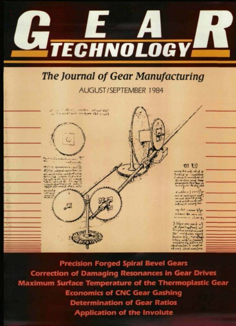
(OVER:<br />
The advanced technology of<br />
LEONARDO DA VINCI<br />
1452-1519<br />
It has been XlrcI [hat Leonardo Da<br />
Vmo was one oIlhe fllOSI exrraorCllflary<br />
geniUses who has ever lived In a seres<br />
of notebooks, he recorded deSCriptIOns,<br />
draW<strong>in</strong>gs. and diagrams of "Inventions"<br />
whICh were centuries berore <strong>the</strong>ir orne<br />
Leonardo comprehenSIVely Sludlt'd each<br />
problem and derived <strong>the</strong> operaoon 0(<br />
mach<strong>in</strong>es from ma<strong>the</strong>matical <strong>the</strong>ory<br />
The cover sketch IS a deSJ9n for a<br />
water-pcwereo mechanism for form<strong>in</strong>g<br />
me stave 01" segment of a gun-b.3rreL The<br />
barrel Would be bUI/[ of several of <strong>the</strong>se<br />
segments These .segment5 would be<br />
banded toge<strong>the</strong>r. heaver at <strong>the</strong> txeecn<br />
secnon than al me rnuzze All seqrnerns<br />
were [0 be 'llTlOOth a'ld even. witt! a<br />
un form taper m order [0 obt(lIn a stra!9hl<br />
gas·prootbore Leonardo also deSIgned a<br />
machlt'le that would draw and rOU<strong>the</strong><br />
bars trom one power sooce. a reacnon<br />
water turtllne Through two sets of<br />
worm drives, <strong>the</strong> sheet !fon was<br />
SImultaneously made to advance wh e<br />
be<strong>in</strong>g rOlled.<br />
FEATURES<br />
P,RECJSION ,FORGED SPIRAL BEVEL GEARS<br />
Aly Badawy, P. S. Raghuparhl-Ba~elle Columbus Laboratories<br />
Gary HONat-Earon Corporation<br />
Don Ostberg-U.S. Army Tank Autornonve Command<br />
IDE.NT FICAlilON & CORRECTION OF IDAMlA.GING<br />
REcSONANCES IN' GEAR DRIVES<br />
Loftl E. EI·8ayoumy-Western <strong>Gear</strong> Corporation<br />
MAXIMUM SURFACE TEMPERATURE Of THE THERMOPlASTIC GEAR<br />
IN A NON-LUBRICATED PLASTIC/STEEl. 'GE.A_RPA'IR<br />
Raymond Gauv<strong>in</strong>, Patncl< Girard, Henn Yelle-<br />
Ecole PoIyt.echnique de Montreal<br />
ECONOMICS ,OF CNC GEAR 'GASHING, VS. lARGE D. P. HOPING<br />
Joseph W. ConigliO - Gould & Eberhardt <strong>Gear</strong> Mach<strong>in</strong>ery Co.<br />
DETiE.RMINATION 'OF GEAR RATIO,S<br />
W. C. Orthweln - Sou<strong>the</strong>rn IlhnOls Unlver.si!y<br />
DEPARTMENT,S<br />
AGM_A CALlir-NDAR'<br />
••• AND FROM THE ,INDUSTRY<br />
,NOTES FROM THE IEDIT,OR'S DESK<br />
Michael Gold.steln<br />
'GUEST EDITORIAL<br />
Forresr Brummelt-SocJeCy of Manufactunng<br />
VUEW'IPOINT<br />
Eng<strong>in</strong>eers<br />
SCACK TO BASICS .... FUNCTIONS OF G~AR1NG'AND APPUCATION<br />
'Of THE fNVOlUTIE TO G~AR TEETH<br />
CLASSIFIED<br />
PAGE NO.<br />
<strong>August</strong>i<strong>September</strong> J 984 Vol. I, No.2<br />
SUBSCRIPTION INfORMATION: GEAR TECHNOLOGY ISdlstrlbuled tree of Charge to qualified IndIviduals and firms III [he<br />
gear manurilCl1Jnng ndusuy To COnt<strong>in</strong>ue receiV<strong>in</strong>g your SUbSCflp!lon. complete and mall (he appllc!> ~ 0< ".,. dliha<<br />
POSTM/ISTER !.
AGMA<br />
Calendar<br />
... AND FROM<br />
THE INDUST'RY<br />
The fallow<strong>in</strong>g American <strong>Gear</strong> Manufacturers Association meet<strong>in</strong>gs<br />
are scheduled. For fur<strong>the</strong>r <strong>in</strong><strong>format</strong>ion, please call AGMA<br />
703-525-1600.<br />
Sept. 5-6,<br />
<strong>1984</strong><br />
Metallurgy and Materials Committee (I b)<br />
Hyatt Chicago O'Hare, Chicago, IL<br />
Sept. 10-1r.<br />
<strong>1984</strong><br />
Handbook and Inspection Committee 13c)<br />
AGM'A Headquarters, Arl<strong>in</strong>gton, VA<br />
Sept. 11,<br />
<strong>1984</strong><br />
Sept. 12,<br />
<strong>1984</strong><br />
Sept. 13-14,<br />
<strong>1984</strong><br />
Sept. 17-18,<br />
<strong>1984</strong><br />
Sept. 19,<br />
<strong>1984</strong><br />
Sept. 19,<br />
<strong>1984</strong><br />
Sept. 20-21,<br />
<strong>1984</strong><br />
Sept. 25-26,<br />
<strong>1984</strong><br />
Sept. 27,<br />
<strong>1984</strong><br />
Sept. 27,<br />
<strong>1984</strong><br />
Sept. 28,<br />
<strong>1984</strong><br />
Oct. 14-17,<br />
<strong>1984</strong><br />
Nov. 8-9<br />
<strong>1984</strong><br />
"Product Division Executive Committee<br />
Westpark Hotel. Arl<strong>in</strong>gton, VA<br />
*Technical Division Executive Committee<br />
AGMA Headquarters, Arl<strong>in</strong>gton, VA<br />
Helical, Herr<strong>in</strong>gbone, andlor Spiral Bevel Enclosed<br />
Drives and Standard Units Committee (6.3a)<br />
AGMA Headquarters, Arl<strong>in</strong>gton, VA<br />
<strong>Gear</strong> Rat<strong>in</strong>g Committee (Set<br />
Brown Palace, Denver, CO<br />
"Policy & Practice Guides Stand<strong>in</strong>g Committee<br />
Brown Palace, Denver, CO<br />
Component Design Committee /5bl<br />
7 Conenents Hotel, Chicago, IL<br />
Mill Geanng Committee (2cI<br />
AGMA Headquarters, Arl<strong>in</strong>gton, VA<br />
Helical and Herr<strong>in</strong>gbone Drives Shalt Moumed<br />
Units Committee (6.3bJ<br />
AGMA Headquarters, Arl<strong>in</strong>gton, VA<br />
*Flexible Coupl<strong>in</strong>gs Council<br />
West<strong>in</strong> Hotel, Copley 5t.. Boston. MA<br />
*Statistical Subcommittee, Market<strong>in</strong>g Council<br />
West<strong>in</strong> Hoter, Coprey Sr., Boston, MA<br />
"Market<strong>in</strong>g Council<br />
West<strong>in</strong> Hotel. Copley 51:.. Boston, MA<br />
FarrTechnical Meet<strong>in</strong>g<br />
L'Enfant praza Hotel. Wash<strong>in</strong>gton,<br />
Bevel <strong>Gear</strong><strong>in</strong>g Committee (4a)<br />
AGMA Headquarters, Arl<strong>in</strong>gton, VA<br />
D.C.<br />
I<br />
II<br />
H~RMAN RICCIO, CHICAGO 'GEAR WORKS<br />
PRESIDENT TO' RETIRE<br />
Herman, ,RIccio, [ongetime President of Chicago <strong>Gear</strong> Works,<br />
<strong>the</strong> company he lead to natJonal prom<strong>in</strong>ence <strong>in</strong> <strong>the</strong> commercial<br />
gear <strong>in</strong>dusUy, will retire <strong>in</strong> November, <strong>1984</strong> after 55 years of serv-<br />
Ice. He began work<strong>in</strong>g at Chicago <strong>Gear</strong> Works <strong>in</strong> 1929, at <strong>the</strong> age<br />
of 1'5. and never worked for ano<strong>the</strong>r company.<br />
In a recent <strong>in</strong>terview, Riccio reiterated his basic bus<strong>in</strong>ess philosophy,<br />
"Try giv<strong>in</strong>g <strong>the</strong> customers <strong>the</strong> best service you can. Give <strong>the</strong>m<br />
quality. You can't stand still." Riccio proved that himself by retir<strong>in</strong>g<br />
once before, In 1982, only to return six months later.<br />
Mr. RicciObegan his work at Chicago <strong>Gear</strong> Works asjanitcrand<br />
errand boy, work<strong>in</strong>g for 26 It/hour. He was nearly fired when he<br />
requested a one-cent raisel However, by 1937,.he had moved to<br />
<strong>the</strong> office as assistant to <strong>the</strong> Vice-President for Manufactur<strong>in</strong>g and<br />
Eng<strong>in</strong>eer<strong>in</strong>g. Fourteen years later, he assumed those responsibilities<br />
himself as Executive Vice-President for Manufactur<strong>in</strong>g; and <strong>in</strong> 1967,<br />
Riccio and two partners purChased Chicago <strong>Gear</strong> Works.<br />
Although Mr. Riccio states that he is "retir<strong>in</strong>g," he will cont<strong>in</strong>ue<br />
work<strong>in</strong>g I-Z days per week and will be an active member of <strong>the</strong><br />
management committee.<br />
GLEASON OPENS MI SALES O'F,FICE<br />
The ,Gleason Works announces <strong>the</strong> <strong>format</strong>ion of a regional<br />
sales office <strong>in</strong> <strong>the</strong> greater Detrojt area. 'Geoffrey Ashcroft has<br />
been named Regional SalesManager and wiH be coord<strong>in</strong>at<strong>in</strong>g <strong>the</strong><br />
sales and service of Gleason Equipment <strong>in</strong> <strong>the</strong> Michigan area.<br />
Ashcroft, who was associated with <strong>the</strong> company's overseas dealer<br />
network <strong>in</strong> <strong>the</strong> 1960's, has a wide range of experience with bevel<br />
and parallel axis mach<strong>in</strong>ery and technology<br />
This announcement closely foJiows Gleason's recent press release<br />
<strong>in</strong>augurat<strong>in</strong>g a new domestic market<strong>in</strong>g philosophy with <strong>the</strong><br />
sign<strong>in</strong>g of <strong>the</strong>ftrst domestic dealership with State Mach<strong>in</strong>ery Co .•<br />
rnc. of Indianapolis, Indiana.<br />
James E .. Cronkwright. Vice President of Market<strong>in</strong>g, <strong>in</strong> comment<strong>in</strong>g<br />
on today'S announcement, has noted <strong>the</strong> importance of<br />
quick customer response <strong>in</strong> toeay's competitive economy.<br />
"Company Member employees only or Specified members of<br />
committees.<br />
PETERSON JOINS AMERICAN PFAUTER<br />
Steve Peterson has jo<strong>in</strong>ed Amer,lcan ,Pfauter ,Llmlted '<br />
, !:Jk<br />
Grove Village, fL as Regional Sales Manager. Steve br<strong>in</strong>gs over 20<br />
years of experience <strong>in</strong> <strong>the</strong> mach<strong>in</strong>e tool <strong>in</strong>dustry support eqUipment<br />
field. Steve will be responSible For technical sales and customer<br />
support of Pfauter gear cutt<strong>in</strong>g, Hoefler gear <strong>in</strong>spection, Kapp gr<strong>in</strong>d<strong>in</strong>g,<br />
and Sykes shap<strong>in</strong>g applications.<br />
LeO'TeOhno,ogy
----<br />
N'OTES FROWI THE ED'ITOR'S<br />
DE,SK<br />
THANK YOUI ... <strong>the</strong> response to our first issue<br />
has been extremely excit<strong>in</strong>g' for us. Our advertisers<br />
have told us GEAR TECHNOLOGY is be<strong>in</strong>g talked<br />
about wherever <strong>the</strong>y go. Thank you for <strong>the</strong><br />
wonderful and enthusiastic reception.<br />
Our response to <strong>the</strong> subscription card <strong>in</strong> <strong>the</strong> last<br />
issue has far exceeded our expectations. We have<br />
been receiv<strong>in</strong>g response cards at an average of 100<br />
per day. As we are <strong>in</strong> <strong>the</strong> process of chang<strong>in</strong>g computer<br />
systems, and implement<strong>in</strong>g new mail<strong>in</strong>g list<br />
sottware, we will be a Irmedelayed add<strong>in</strong>g new subscribers.<br />
Thus, if you recommended someone to receive<br />
"The Journat" it is likely <strong>the</strong>y won't be added to <strong>the</strong> subscription list until <strong>the</strong> third <strong>Issue</strong>.<br />
There are a few ways <strong>in</strong> which you can help us do a betterjab. If you have a "Free<br />
Subscription" <strong>in</strong>sert <strong>in</strong> your book. it means you probably didn't fi" out <strong>the</strong> subscription card <strong>in</strong><br />
<strong>the</strong> last issue,it got lost, or you forgot to fi" <strong>in</strong> your company name. Even if this issueisaddressed<br />
to you, please fill it out COMPLETELYand SIGN it. This is needed for post office regulations. The<br />
quicker we meet [he postal regulations by gett<strong>in</strong>g a SIGNED card from EVERYONE <strong>the</strong> sooner<br />
we can concentrate all our efforts on <strong>the</strong> contents. If only an editorial reply card can be found <strong>in</strong><br />
your magaz<strong>in</strong>e, thank you, we have already received your signed subscription card; but don't<br />
forget to tell us what you thought of <strong>the</strong> articles. Send us your comments on any subject. IWe<br />
might <strong>in</strong>clude it <strong>in</strong> "Viewpo<strong>in</strong>t. "J We <strong>in</strong>vite you to tell us what you want to see<strong>in</strong> future issues.<br />
We have been <strong>in</strong> contact With prospective researchersand authors all over <strong>the</strong> world and<br />
have a cont<strong>in</strong>u<strong>in</strong>g mterest <strong>in</strong> receiv<strong>in</strong>g new articles. Have you developed a new techniquel<br />
process, or solved some unusual problem that would be of <strong>in</strong>terest to <strong>the</strong> gear manufactur<strong>in</strong>g<br />
community7 Tell us about it so we can consider publish<strong>in</strong>g it. Articles submitted should be<br />
written from an educationaland/or tra<strong>in</strong><strong>in</strong>g viewpo<strong>in</strong>t. Everyth<strong>in</strong>g we publish, however,<br />
may not be new. We will be publish<strong>in</strong>g papers that may have been presented at technical<br />
conferences, or published <strong>in</strong> small circulation or foreign publications. but if we decide <strong>the</strong>y<br />
deserve a wider audience, <strong>the</strong>y wifl be published.<br />
F<strong>in</strong>ally, our objective is not only to be <strong>in</strong><strong>format</strong>ive but also to help you get more ousness<br />
Virtually everyone hav<strong>in</strong>g anyth<strong>in</strong>g to do with <strong>the</strong> gear bus<strong>in</strong>ess receives "The Journal."<br />
Wouldn't an ad <strong>in</strong> GEAR TECHNOLOGY be a natural way to tell your potential customers<br />
someth<strong>in</strong>g about your company, and to expand your customer base? The classifiedswill f<strong>in</strong>d<br />
that eng<strong>in</strong>eer, that job for your special or unique mach<strong>in</strong>e, etc.... Please,just keep us <strong>in</strong> m<strong>in</strong>d.<br />
Aug,ust-Sepfember 1,984 .5
GUEST EDITOItlAI4<br />
A SECOND RATE SOCIETY -<br />
NEVER!<br />
What was<br />
once recognized<br />
as <strong>the</strong> unique<br />
genius of<br />
America is now<br />
slipp<strong>in</strong>g away<br />
from us and, <strong>in</strong><br />
many areas, is<br />
now seen as a<br />
"second rate" capability.<br />
Unless<br />
action is taken<br />
now, this country<br />
For~1t O. Brummett, SME's<br />
is <strong>in</strong> real dan-<br />
ger of be<strong>in</strong>g<br />
t9B4-85Int~rnatlon.' P,~sldenr. unable to rega<strong>in</strong><br />
its supremacy <strong>in</strong><br />
technological development and economic vigor. F,irst aU<br />
Americans must understand <strong>the</strong> serious implications of <strong>the</strong><br />
problem; and second, we must dedicate ourselves to national<br />
and local actions that will ensure a greater scientific and<br />
technological literacy <strong>in</strong> America.<br />
To help all of us understand <strong>the</strong> problem, let me cite just a<br />
few facts:<br />
• Many of our nation's high schools do not offer <strong>the</strong> necessary<br />
math and science courses to qualify <strong>the</strong>ir graduates for consideration<br />
by our accredited Eng<strong>in</strong>eer<strong>in</strong>g <strong>in</strong>stitutions.<br />
MR. FOREST BRUMMETT, author of <strong>the</strong> "Guest Editorial,"<br />
is Chief Eng<strong>in</strong>eer at DetrOit Diesel Allison Division of<br />
General Motors Corporation - Indianapolis OperatiOns. He<br />
jo<strong>in</strong>ed Detroit Diesel <strong>in</strong> May of 1949 and has held responsible<br />
positions <strong>in</strong> Production, Tool & Die Mak<strong>in</strong>g, Tool & Die Design,<br />
Plant Eng<strong>in</strong>eer<strong>in</strong>g, Methods Eng<strong>in</strong>eer<strong>in</strong>g, CAD/CAM<br />
Systemsand Capacity Management. Active <strong>in</strong> <strong>the</strong> Society of<br />
Manufactur<strong>in</strong>g Eng<strong>in</strong>eers s<strong>in</strong>ce /962 hold<strong>in</strong>g office at Chapter,<br />
Region, and Internationalleve/s. He served on <strong>the</strong> s.M.E.<br />
Technical Council es Chairman of <strong>the</strong> Assembly Division and<br />
became chairman of <strong>the</strong> Technical Council for {2} terms <strong>in</strong><br />
1975 through 1977. Currently Intemational President of<br />
s.M.£. and has been on <strong>the</strong> Board of Directors for <strong>the</strong> past 12<br />
years. In addition, Mr. Brummett is among those listed as<br />
Who's Who <strong>in</strong> Eng<strong>in</strong>eer<strong>in</strong>g <strong>in</strong> America. He is a Certified<br />
Manufactur<strong>in</strong>g Eng<strong>in</strong>eer <strong>in</strong> <strong>the</strong> field of Genera/ Manufactur<strong>in</strong>g<br />
Eng<strong>in</strong>eer<strong>in</strong>g. Mr. Brummett attended Purdue University and<br />
received his Bachelors Degree <strong>in</strong> Mechanical Eng<strong>in</strong>eer<strong>in</strong>g.<br />
• Educational <strong>in</strong>stitutions throughout <strong>the</strong> country report an<br />
ever <strong>in</strong>creas<strong>in</strong>g number of students cannot read and comprehend,<br />
and are nor prepared to select careers <strong>in</strong> science and<br />
technology. Remedial courses <strong>in</strong> both Read<strong>in</strong>g and Ma<strong>the</strong>matics<br />
are <strong>the</strong> order of <strong>the</strong> day. In addition, <strong>the</strong>se same <strong>in</strong>stitutions<br />
report that <strong>the</strong>re is a woeful lack of people qualified to<br />
teach courses <strong>in</strong> modern Math, Eng<strong>in</strong>eer<strong>in</strong>g, and Natural Seience.<br />
Many advanced courses <strong>in</strong> high schools, colleges, and<br />
universities languish through lack of qualified teachers.<br />
• There is very little "real world" career guidance at <strong>the</strong> secondary<br />
school level <strong>in</strong> <strong>the</strong> area of Eng<strong>in</strong>eer<strong>in</strong>g, Technology, and<br />
<strong>the</strong> Free Enterprise System. Consequently, when students get<br />
<strong>in</strong>to college, many choose <strong>the</strong>se careers without adequate<br />
preparation as <strong>the</strong>y become aware of <strong>the</strong> potential opportunities<br />
<strong>in</strong> <strong>the</strong>se fields.<br />
The end result to this dilemma is that <strong>in</strong>dustry ends up with<br />
a product <strong>the</strong>y cannot utilize without major tra<strong>in</strong><strong>in</strong>g and redirection.<br />
This po<strong>in</strong>ts up what I believe, is one of <strong>the</strong> most<br />
serious problems fac<strong>in</strong>g American <strong>in</strong>dustry today - <strong>the</strong> technical<br />
illiteracy of its eng<strong>in</strong>eers, managers, and executives. Few<br />
of <strong>the</strong>m, due to lack of adequate tra<strong>in</strong><strong>in</strong>g <strong>in</strong> <strong>the</strong> academia,<br />
have <strong>the</strong> skills to solve "real world" problems and implement<br />
current and new technology required to compete <strong>in</strong> <strong>the</strong><br />
marketplace today or <strong>in</strong> <strong>the</strong> future. Bus<strong>in</strong>ess decisions require<br />
weigh<strong>in</strong>g variables, such as sales and costs. product quality<br />
and prOductivity, price and market share, profrt and taxes.<br />
Many of our managers aren't well equipped to reason and<br />
th<strong>in</strong>k <strong>in</strong> those terms. Is it any wonder that <strong>the</strong>y are drawn to<br />
legal or f<strong>in</strong>ancial solutions ra<strong>the</strong>r than technical or human<br />
ones?<br />
New and <strong>in</strong>novative technological concepts have brought<br />
about a clear awareness and recogni!:ion of <strong>the</strong> need for <strong>the</strong><br />
secondary schools and universities to produce an abundant<br />
supply of "hands on," "real WOrld," "applications oriented,"<br />
<strong>in</strong>dividuals that more adequately meet <strong>the</strong> needs of today's<br />
<strong>in</strong>dustries. This means updat<strong>in</strong>g and improvjng<strong>the</strong> technology,<br />
eng<strong>in</strong>eer<strong>in</strong>g, and science curriculum; and provid<strong>in</strong>g <strong>the</strong><br />
most modern Lab facilities and teach<strong>in</strong>g methods available.<br />
In addition. <strong>the</strong> faculty must be given <strong>the</strong> opportunity for<br />
updat<strong>in</strong>g <strong>the</strong>ir skills as new technology emerges, and as current<br />
technology changes. Here<strong>in</strong> lies <strong>the</strong> need for <strong>in</strong>teraction<br />
between <strong>the</strong> academia, <strong>in</strong>dustry, and <strong>the</strong> government.<br />
S<strong>in</strong>ce we cannot predict, with any precision, what k<strong>in</strong>d of<br />
jobs people will hold over <strong>the</strong>ir 35-40 year work<strong>in</strong>g life, it is<br />
best to provide a good general education with an ability to<br />
adapt to chang<strong>in</strong>g jobs and careers. If work requirements<br />
change abruptly and quickly. <strong>the</strong> educational system must<br />
6 Geo'r Techno'iogy
espond faster and more efficiently to tra<strong>in</strong><strong>in</strong>g needs. This will<br />
require better ties with <strong>in</strong>dustry and should not exclude <strong>the</strong><br />
possibility of more <strong>in</strong>dustry based activities.<br />
Like it or not we are <strong>in</strong> an <strong>in</strong>ternational marketplace that<br />
imp<strong>in</strong>ges on our nation much more than <strong>the</strong>y used to, and<br />
basic Institutions must change to account for that.<br />
The trends are now reflect<strong>in</strong>g <strong>the</strong> loss of our technological<br />
edge. e.q.: We have allowed our piece of <strong>the</strong> world trade to<br />
drop from 17% to 12% from 1965 to 1983 while <strong>the</strong> volume<br />
of <strong>in</strong>temational trade <strong>in</strong>creased From ISO billion to 1.9 trillion.<br />
For example, we have lost our share of <strong>the</strong> world market <strong>in</strong><br />
consumer electronics from 35% to 9% <strong>in</strong> <strong>the</strong> last 15 years.<br />
These are depress<strong>in</strong>g facts and it will take an enormous<br />
amount of concerted action by all Americans to overcome<br />
this terrible handicap. whIch we are now recogniz<strong>in</strong>g and<br />
which will commit us to mediocrity and second rate. if not<br />
addressed. Technology impacts all our lives II<br />
Citizens need to change <strong>the</strong>ir atotudes on manufactur<strong>in</strong>g<br />
technology to become economically more responsible. This<br />
also beg<strong>in</strong>s <strong>in</strong> <strong>the</strong> educational system. A. long range view is<br />
needed to emphasize technical <strong>in</strong>novation. <strong>in</strong>creased productivity,<br />
and quality improvements. We must leam how to produce<br />
more than we consumel<br />
The time is here - we are an <strong>in</strong>dustrial nation In deep<br />
trouble. We can no longer afford' <strong>the</strong> luxury of confrontation.<br />
Traditional adversary relationships must be tempered by <strong>the</strong><br />
necessity of <strong>in</strong>dustrial growth and survival. This effort must<br />
beg<strong>in</strong> <strong>in</strong> our educational systems, where specific skills and<br />
knowledge are taught. utiliz<strong>in</strong>g modern teach<strong>in</strong>g methods.<br />
computers. and facilities to produce a product that meets <strong>the</strong><br />
real needs of <strong>in</strong>dustry today and <strong>in</strong> <strong>the</strong> future .<br />
We cannot be bound by tradition; we must <strong>in</strong>itiate change<br />
- flexibility <strong>in</strong> curriculum adjustment to meet current needs as<br />
well as <strong>the</strong> future, based on manufactur<strong>in</strong>g tedlnology<br />
trends. Education is eveyone': responsibility<br />
Forrest Brummett<br />
5III1E. Intemational President<br />
II<br />
I<br />
Letters fo.r this columnshouJd be add Sled 10 Letters<br />
to <strong>the</strong> Edl1or, GEAR'TECHNOL-OGY~ P.O. Box<br />
1426, ,E!llk G,rove Vlllag" IL 60007. ILelters<br />
submitted 10' Ihls colUmn become th prDperty of<br />
GEAR TECHNOLOGY. INames will be wfthh Id'<br />
upon request; howver .. nD ' nonYlllous I' ~-- rs<br />
willi lbe published. Op<strong>in</strong>ions; expr d by ,contributors<br />
ar nol necessarily those 0' <strong>the</strong> editor or publish<strong>in</strong>g<br />
staff'. -<br />
Dear Edi~or:<br />
f read with great <strong>in</strong>terest your first issue of GEAR TECH·<br />
NOlDGY. I f<strong>in</strong>d it a refresh<strong>in</strong>g move based on <strong>the</strong>se economic<br />
times.<br />
I would be most <strong>in</strong>terested <strong>in</strong> communicat<strong>in</strong>g with you on<br />
one of our major concernS-foreign competition. r believe this<br />
willgrea~y affect <strong>the</strong> <strong>in</strong>dustry more than any technological<br />
change now or <strong>in</strong> <strong>the</strong> foreseeable future. Foreign compedtion,for<br />
all <strong>the</strong> reasons we have heard, is mak<strong>in</strong>g startl<strong>in</strong>g<br />
<strong>in</strong>roads <strong>in</strong>to <strong>the</strong> available market of <strong>the</strong> Amelican gear<br />
manufacturers. In some cases, based on <strong>the</strong> company's size,<br />
overhead expenses and services rendered, I can certa<strong>in</strong>ly understand<br />
how <strong>the</strong>se companies can be competitive. This situation<br />
even occurs <strong>in</strong> some of our smaller gear companies<br />
when <strong>the</strong>y are compared price-wise to some of our ,larger<br />
companies with<strong>in</strong> this country,<br />
But. I can tell you that we've also seen some highly questionable<br />
pric<strong>in</strong>g situations which can only occur because of<br />
some unfair competitive position or a will<strong>in</strong>gness to underm<strong>in</strong>e<br />
our market until it's weakened to <strong>the</strong> po<strong>in</strong>t where tney<br />
can raise <strong>the</strong>ir prices or run <strong>the</strong> competition out of busness.<br />
Some of <strong>the</strong> unfair competition has to <strong>in</strong>clude our tax base<br />
structure compared to <strong>the</strong>irs. based on our cost of defense,<br />
our personal <strong>in</strong>come taxes, our unemployment taxes, our<br />
,benefits programs, etc.<br />
If as a nafion we're s<strong>in</strong>cerely <strong>in</strong>terested <strong>in</strong> ma<strong>in</strong>ta<strong>in</strong><strong>in</strong>g our<br />
standard of liv<strong>in</strong>g and offer<strong>in</strong>g all <strong>the</strong>se opportunities, <strong>the</strong>n<br />
our <strong>in</strong>dustries must be strong. For our <strong>in</strong>dustries to stay<br />
srrong,<strong>the</strong>y must stay productive. To do this. we must be on<br />
a fair competitive basis with those people that compete<br />
aga<strong>in</strong>st us.<br />
When I speak of unfair practices. I am not just vocaliz<strong>in</strong>g<br />
"sour grapes" s<strong>in</strong>ce we are a strong advocate of free trade.<br />
However, we are Frnd<strong>in</strong>g <strong>in</strong> <strong>the</strong>se economic times It ISpreposterous<br />
to be bidd<strong>in</strong>g on afede~ally funded work program<br />
(which our tax dollars are pay<strong>in</strong>g ~orjlaga<strong>in</strong>st foreign oompet<strong>in</strong>on,<br />
In o<strong>the</strong>r words. we are pay<strong>in</strong>g corporate <strong>in</strong>come, personal<br />
<strong>in</strong>come. and unemployment <strong>in</strong>surance taxes, and those<br />
funds are be<strong>in</strong>g used to pay our overseas competitors to build<br />
products for our unemployed people. This situation seems<br />
<strong>in</strong>comprehensible to us.<br />
I'm afraid that <strong>the</strong> political issues <strong>in</strong> <strong>the</strong> gear <strong>in</strong>dustry and<br />
this issue alone may be more importam and more imerestlng<br />
than <strong>the</strong> technical side of our <strong>in</strong>dustry.<br />
Aga<strong>in</strong>, f wish you good ,luck <strong>in</strong> this new venture.<br />
S<strong>in</strong>cerely,<br />
MILWAUKEE<br />
Harold Trusky<br />
President<br />
GEAR COMPI'I.NY<br />
<strong>August</strong>·<strong>September</strong> <strong>1984</strong> 7
We meke gear' tnsoection eesvt<br />
i<br />
With <strong>the</strong> modern computercontrolled<br />
2000··4 QC System,<br />
complete gear <strong>in</strong>spection is<br />
remarkably easy,. Now you can<br />
reliably check higlh'precision<br />
gears, cams, hobs and o<strong>the</strong>r<br />
close tolerance parts-faster<br />
and sirnpler than ever before.<br />
All you do is taik to <strong>the</strong><br />
computer. Just say what part<br />
you want to check, what check<br />
you want done, and when you<br />
want to !beg<strong>in</strong>. That's when <strong>the</strong><br />
computer takes over, elim<strong>in</strong>at<strong>in</strong>g.<br />
complex operator tasks.<br />
How could complete<br />
analysis of complex gear<br />
'geometry be so simple? We've<br />
rejected <strong>the</strong>' unreliable<br />
mechanisms of traditional gear<br />
checkers which required <strong>the</strong><br />
attention of skilled and<br />
I cedicated technicians,<br />
Mechanically, <strong>the</strong> M & M 2000-4<br />
is Simple and fundamental.<br />
Three nnear axes carry <strong>the</strong><br />
measurement probe whille <strong>the</strong><br />
rotary axis carries <strong>the</strong> part.<br />
The computer is responsible for<br />
<strong>the</strong>se movements, not <strong>the</strong><br />
techntclan. The computer also<br />
takes responslblllty for data<br />
analysis after <strong>the</strong> test is<br />
complete.<br />
If you're check<strong>in</strong>g: gears<br />
with anyth<strong>in</strong>g except <strong>the</strong> fast,<br />
accurate, and rellabte 2000-4,<br />
you're doi<strong>in</strong>g it <strong>the</strong> hard way.<br />
For more In<strong>format</strong>ion, wriite 'Dr<br />
call your M & M Applications<br />
Engl<strong>in</strong>eer. He'lil see that you<br />
rece:ive' a copy of our new 2000-4<br />
ac System brochure.Bead it<br />
and you'll agree ... "We make<br />
gear <strong>in</strong>spection easy!"<br />
M & M Precision Systems,<br />
300 Progr,ess Road,<br />
West. Carroliliton, Ohlo 45449,<br />
telephone 513/859-8273.<br />
M s M 2000-4 .QC<br />
• Universal gear <strong>in</strong>spection<br />
• Automatic test<strong>in</strong>g<br />
• Ease of operation<br />
• Computer analysis<br />
-Reliable<br />
accuracy<br />
• Applications flexibil'i'ty<br />
')lI,IwaysTh<strong>in</strong>k<strong>in</strong>g<br />
procJuctivity"<br />
M5M PRECISIDN<br />
SYSTEMS - -<br />
AN ACME·CLEVELAND COMPANY
Precision Forged<br />
Spiral Bevel Cears<br />
CAD'/CAM<br />
'Technique Makes, It Practical<br />
by<br />
Aly Badawy<br />
P. S. Raghupathi!<br />
n~atene'sColumbus Laboratories.)<br />
Gary Horva't<br />
(Eaton Corporation)<br />
Don Ostberg<br />
(U.s .. Anny Tank Automotive<br />
Command)<br />
Close tolerance forg<strong>in</strong>g 'of U.S. Army spiral bevel gears,<br />
requir<strong>in</strong>g only a s<strong>in</strong>gle f<strong>in</strong>ish mach<strong>in</strong><strong>in</strong>g operation (or none),<br />
now is feasible <strong>in</strong> production with <strong>the</strong> help of a. newly<br />
developed Computer Aided Design and Manufactur<strong>in</strong>g<br />
(CAD/CAM) technique ..This method of manufacture offers<br />
many advantages because it reduces material. losses and<br />
mach<strong>in</strong><strong>in</strong>g costs while <strong>in</strong>creas<strong>in</strong>g <strong>the</strong> fatigue life of <strong>the</strong> gears<br />
by 30 percent.<br />
A recent U.S. Army Tank-Automotive Command project,<br />
conducted by Battelle's Columbus Laboratories. successfully<br />
developed <strong>the</strong> methodology of CAD/CAM procedures<br />
for manufactur<strong>in</strong>g dies (via EDM) for forg<strong>in</strong>g spiral<br />
bevel gears. Fur<strong>the</strong>r, it demonstrated ,that precision forg<strong>in</strong>g<br />
of spiral bevel. gears. is a practical. production technique.<br />
Although no detailed economic evaluation was made <strong>in</strong> this<br />
study, it is expected that precision .forg<strong>in</strong>g offersan attraclive<br />
alternative to <strong>the</strong> costly gear cutt<strong>in</strong>g operations lor produc<strong>in</strong>g<br />
spiral bevel gears,<br />
CAD and CAM .lntegrated<br />
In <strong>in</strong>dustrial practice, aUemp~s are cont<strong>in</strong>uously made to<br />
<strong>in</strong>troduce improved manufactur<strong>in</strong>g methods to reduce production<br />
and life cycle costs. Close tolerance for~<strong>in</strong>g, of spiral<br />
bevel gears-requir<strong>in</strong>g only a s<strong>in</strong>gle or no f<strong>in</strong>ish mach<strong>in</strong><strong>in</strong>g<br />
AUTHORS:<br />
DR. .ALYBADAWYis Pr<strong>in</strong>cipal' Research Scientist. Eng<strong>in</strong>eer<strong>in</strong>g<br />
.and Manufactur<strong>in</strong>g Technology Department for<br />
Battelle's Col'umbus Labot:atories. His experience covers resear:ch<br />
and detJ.elopment <strong>in</strong> Mar<strong>in</strong>e Eng<strong>in</strong>eer<strong>in</strong>g and Naval<br />
A rckl'tecture, Applicmio.l15 of Optimization Theory <strong>in</strong> Design,<br />
Computer Aided Design and Interactive Computer<br />
Graphics, and Geometrical Model<strong>in</strong>g of Sculptured and<br />
Comp.tex Surfaces. Dr. Badawy has author;ed or co-authored<br />
15 technical papers related to Computer A ided Design and<br />
Computer Gt:aphics. He holds a .B. Se, from Alexa.ndria University.<br />
and a M. Eng. and' a Ph. D. from McMaster University,<br />
Canada. Additionally. he is a member of <strong>the</strong> American<br />
Society of Mechanical Eng<strong>in</strong>eers, Compu.ter Aided Design<br />
Committee.<br />
DR. P. S. RAGHUPA1HI'S experience is <strong>in</strong> <strong>the</strong> area of<br />
cold ,extrusion, closed die forg<strong>in</strong>g, deep draw<strong>in</strong>g, metal<br />
form<strong>in</strong>g mach<strong>in</strong>e tools and computer aided design and<br />
manufactur<strong>in</strong>g. He is cunent~y <strong>the</strong> Associate Manager, Metalwork<strong>in</strong>g<br />
Section of Battelle:s Columbus Labor;atories. In<br />
addition to be<strong>in</strong>g <strong>the</strong>authorlco~authorof mor;e than 20 publicatiol15,<br />
he is also. a co-editor of a Metal Form<strong>in</strong>g Handbook<br />
which is soon .to be published ..Dr. Raghupathi holds a B'. E.,<br />
University of Madras, India; M. 15. .from Indian 1I15titute of<br />
Science, and a Dr. lng. from <strong>the</strong> University of Stuttgart, W.<br />
Gemaany. Asa member of <strong>the</strong> Intematiomd Cold Forg<strong>in</strong>g<br />
Group based <strong>in</strong> Europe, he ma<strong>in</strong>ta<strong>in</strong>s dose contact with' European<br />
Universities, research laboratories rmd companies ac-<br />
Hue ifl. maflufactur<strong>in</strong>g technology.<br />
MR.. 'GARY L HORVAT has been employed ,at Eaton<br />
Corporation s<strong>in</strong>ce 1977. His work <strong>in</strong> Forg<strong>in</strong>g ,and Forg<strong>in</strong>g<br />
Development at various Eaton Divisions has given him a<br />
unique background <strong>in</strong> <strong>the</strong> prec-ision forg<strong>in</strong>g of geArs. Currently,<br />
Mr. Horvat is a M3~nufactur<strong>in</strong>g Developmerd Eng<strong>in</strong>eer.<br />
He ,attended Cleveland State University, graduat<strong>in</strong>g<br />
with ,a B. and M.S. Industrial Eng<strong>in</strong>eer<strong>in</strong>g. He is a member of<br />
Americafl Society for Metals, Society of Manufacturi'ng Eng<strong>in</strong>eer<strong>in</strong>g,<br />
CASA, Computer and AutomAted Systems Association<br />
of S.M.E.<br />
MR. DON 'OSTBERG is currently a Materials Eng<strong>in</strong>eer for<br />
<strong>the</strong> United States Army Tank Automotive Command. He<br />
has been Qt TACOM s<strong>in</strong>ce June 1977. Dur<strong>in</strong>g this time he<br />
has been <strong>in</strong>volved <strong>in</strong> <strong>the</strong> manufactur<strong>in</strong>g teclmology efforts.<br />
Mr. Ostberg studied at Cleveland State Univ.ersl~ty and<br />
holelsa BA <strong>in</strong> Chemica' Eng<strong>in</strong>e.er<strong>in</strong>g.<br />
<strong>August</strong>-<strong>September</strong> <strong>1984</strong> 9'
operation-offers considerable advantage over mach<strong>in</strong><strong>in</strong>g,<br />
because this method. of manufacture (1) reduces material<br />
losses and mach<strong>in</strong><strong>in</strong>g costs and (2)' <strong>in</strong>creases <strong>the</strong> fatigue life<br />
of gears up to 30 percent.<br />
A few companies around <strong>the</strong> world are able to produce<br />
spiral bevel gears by precision forg<strong>in</strong>g, However, <strong>the</strong><br />
development of <strong>the</strong> process for each new gear design requires<br />
considerable trial anderror, Thus, application of<br />
computer techniques to <strong>the</strong> design and. manufacture<br />
(CAD/CAM) of <strong>the</strong> gear forg<strong>in</strong>g dies represents an attractive<br />
alternative. Therefore, <strong>in</strong> this program, methods were<br />
developed to applyexisHng advanced computer aided<br />
design and manufactur<strong>in</strong>g (CAD/CAM) technology (f<strong>in</strong>ite<br />
element, metal form<strong>in</strong>g, and heat transfer analysis) to gear<br />
forg<strong>in</strong>g die design and manufacture. <strong>Gear</strong> forg<strong>in</strong>g dies were<br />
designed and manufactured accord<strong>in</strong>g to <strong>the</strong> data supplied.<br />
by <strong>the</strong> output of <strong>the</strong> CAD procedure; thus, <strong>the</strong> CAD and<br />
CAM processes were <strong>in</strong>tegrated. The results of <strong>the</strong><br />
CAD/CAM techniques were evaluated for a given spiral<br />
bevel. gear/p<strong>in</strong>ion set by design<strong>in</strong>g and manuJactur<strong>in</strong>g <strong>the</strong><br />
forg<strong>in</strong>g dies via CAD/CAM.<br />
In recent years, CAD/CAM techniques have been applied<br />
to. die design and manufacture for forg<strong>in</strong>g rib-web type aircraft<br />
structural parts, track shoes for military vehicles, and<br />
precision turb<strong>in</strong>e and compressor blades. The experience<br />
ga<strong>in</strong>ed <strong>in</strong> all <strong>the</strong>se applications <strong>in</strong>dicates that acerta<strong>in</strong><br />
overall methodology is necessary for CAD/CAM of dies for<br />
precision and/or near net shape forg<strong>in</strong>g. This approach <strong>in</strong>dicates<br />
that <strong>the</strong> necessary <strong>in</strong>puts to <strong>the</strong> CAD/CAM system<br />
are: geometric description of '<strong>the</strong> forg<strong>in</strong>g, data on billet<br />
material under forg<strong>in</strong>g conditions (billet and die temperatures<br />
and rate and amount of de<strong>format</strong>ion)',mction coefficient,<br />
to. quantify <strong>the</strong> friction shear stress at material and die<br />
i.nterface, and forg<strong>in</strong>g conditions [i.e., temperatures, de<strong>format</strong>ion<br />
rates, die lubricants, method of heati<strong>in</strong>g <strong>the</strong> billets,<br />
and suggested number oJ forg<strong>in</strong>g operations) ..<br />
With <strong>the</strong>se <strong>in</strong>put data, a prelim<strong>in</strong>ary design of <strong>the</strong> f<strong>in</strong>ish<br />
forg<strong>in</strong>g die can be made. Next, stresses necessary to f<strong>in</strong>ish<br />
forge <strong>the</strong> part and temperatures <strong>in</strong> <strong>the</strong> forg<strong>in</strong>g and <strong>the</strong> dies<br />
are calculated. The temperature calculations take <strong>in</strong>to ac-<br />
COUJ1t <strong>the</strong> heat generated due '10' de<strong>format</strong>ion and friction,<br />
and <strong>the</strong> heat transfer dur<strong>in</strong>g <strong>the</strong> contact between <strong>the</strong> hot<br />
forg<strong>in</strong>g and <strong>the</strong> cooler dies. Thus, <strong>the</strong> elastic die deflections.<br />
due Ito temperatures and stresses, can be 'estimated and used<br />
to predict <strong>the</strong> small corrections necessary on <strong>the</strong> f<strong>in</strong>ish die<br />
geometry .. The estimation of die geometry correerions is<br />
necessary ror obta<strong>in</strong><strong>in</strong>g dose tolerance forg<strong>in</strong>gs and for<br />
mach<strong>in</strong><strong>in</strong>g <strong>the</strong> f<strong>in</strong>ish dies 'to <strong>the</strong> exact dimensions,<br />
ThE! overall procedure described above has been applied<br />
to CAD/CAM of spiral bevel gears as Phase I of this<br />
project.<br />
The second part of <strong>the</strong> project (Phase ]I) <strong>in</strong>volved Computer<br />
Aided Manufactur<strong>in</strong>g (CAM) of <strong>the</strong> forg<strong>in</strong>g dies (from<br />
rough bi1let) and demonstration of <strong>the</strong> effectiveness of<br />
CAD/CAM hy forg<strong>in</strong>g 20 spiral bevel gear sets. Phase<br />
m-AppJication of CAD/CAM techniques to actual production<br />
of bevel gears (spiral or straight)-has not yet<br />
started.<br />
Five Tasks Carried Out<br />
Five separate tasks were carried out under Phase I of '<strong>the</strong><br />
work preform design, tool design, manufactur<strong>in</strong>g of forg<strong>in</strong>g<br />
dies, forg<strong>in</strong>g trials, and f<strong>in</strong>ish<strong>in</strong>g and dimensional check<strong>in</strong>g<br />
of forged gears,<br />
One of <strong>the</strong> most important aspects of <strong>the</strong> forg<strong>in</strong>g process<br />
is <strong>the</strong> proper design of preform<strong>in</strong>g (or block<strong>in</strong>g) operations.<br />
The follow<strong>in</strong>g features were considered <strong>in</strong> <strong>the</strong> design of <strong>the</strong><br />
preform of <strong>the</strong> spiral bevel gear considered <strong>in</strong> this project.<br />
ASSUf\e Defect free Metal Ro,wa:nd Adequate Die Fill<strong>in</strong>g.<br />
Adequate metal distribution is necessary <strong>in</strong> <strong>the</strong> blocker<br />
design Itoavoid forg<strong>in</strong>g defects, such as cold shuts and folds ..<br />
The preform was designed as a solid r<strong>in</strong>g (no teeth) with <strong>the</strong><br />
outer dimensious as dose as possible to <strong>the</strong> outer dimensions<br />
of <strong>the</strong> f<strong>in</strong>ished gear. This m<strong>in</strong>imlzes <strong>the</strong> amount of material<br />
to be moved dur<strong>in</strong>g forg<strong>in</strong>g, and this <strong>in</strong> turn, enhances die<br />
fiU<strong>in</strong>g.<br />
M<strong>in</strong>imize <strong>the</strong> Material Lost <strong>in</strong> <strong>the</strong> Rash. In steel forg<strong>in</strong>gs,<br />
approximately half of <strong>the</strong> cost of forg<strong>in</strong>g consists of material<br />
~----------------7~'--------------~~<br />
.260"R<br />
1. '"<br />
fIaure I<br />
...----------I.08O"'-----------...-t<br />
NOTE: R_III .37&" unl.. oth__ nobd.<br />
~~--------------------------a~'--------------------------~~
' .......<br />
2 DIe .. "-th,<br />
ẹ ..........<br />
• KJaIIo8t .....<br />
2-8 DIe~<br />
3 ,.... DllIotIDm<br />
5 Die R<strong>in</strong>g<br />
7 Pnform<br />
costs. On <strong>the</strong> average •.30 percent of <strong>the</strong> <strong>in</strong>com<strong>in</strong>g forg<strong>in</strong>g<br />
stock is lost <strong>in</strong> <strong>the</strong> form of flash. Thus, apprcximately 15<br />
percent ,of <strong>the</strong> f,org<strong>in</strong>g costs are <strong>in</strong> <strong>the</strong> flash material of<br />
relatively little recoverable scrap value. The design ot <strong>the</strong><br />
blocker ,of <strong>the</strong> gear produced no flash. This was because <strong>the</strong><br />
volume (or weight) of <strong>the</strong> preform was slightly larger than<br />
<strong>the</strong> volume of <strong>the</strong> f<strong>in</strong>ish gear, and that <strong>the</strong> proper material<br />
distribution throughout <strong>the</strong> preform volume was achieved.<br />
Cen~~r<strong>in</strong>gof Preform <strong>in</strong> Die. The preform was designed<br />
as a pancake with its center ly<strong>in</strong>g exactly on <strong>the</strong> center of <strong>the</strong><br />
die. This was thought to <strong>in</strong>sure even fill<strong>in</strong>g o.f <strong>the</strong> die cavity.<br />
With <strong>the</strong> above considerations, an <strong>in</strong>itial preform design<br />
was developed as shown <strong>in</strong> fig. 1. Fig ..2 shows <strong>the</strong> preform<br />
positioned <strong>in</strong> <strong>the</strong> die. As discussed later, a subsequent<br />
preform was designed and used <strong>in</strong>. <strong>the</strong> forg<strong>in</strong>g trials. The<br />
new design shown <strong>in</strong> fig. :3 was wider, so that <strong>the</strong> metal<br />
would not have to move very far to fill <strong>the</strong> cavity. The size<br />
of <strong>the</strong> corner radii was also reduced to, provide more<br />
material at <strong>the</strong> comers. The billet material, that was used for<br />
forg<strong>in</strong>g spiral bevel gears, was cut from bar stock. The billet<br />
was upset to form a pancake hav<strong>in</strong>g <strong>the</strong> proper diameter.<br />
The pancake was subsequently mach<strong>in</strong>ed to <strong>the</strong> dimensions<br />
specified for <strong>the</strong> preforms,<br />
Tool Deslgn<br />
The forge tool<strong>in</strong>g was designed by us<strong>in</strong>g <strong>the</strong> results of<br />
Phase I of this project. The die assembly is a two piece<br />
design. The die <strong>in</strong>sert. with <strong>the</strong> teeth, is one piece w:ith a. die<br />
r<strong>in</strong>g around <strong>the</strong> <strong>in</strong>sert to, form <strong>the</strong> outer diameter of <strong>the</strong> forg<strong>in</strong>g.<br />
A't <strong>the</strong> center of <strong>the</strong> die is <strong>the</strong> die <strong>in</strong>sert and <strong>the</strong> center<br />
kiekour, The <strong>in</strong>sert forms <strong>the</strong> <strong>in</strong>ner diameter of <strong>the</strong> forg<strong>in</strong>g,<br />
while <strong>the</strong> kickout removes <strong>the</strong> gear from <strong>the</strong> die after forg-<br />
mg. The kickout is designed to lift <strong>the</strong> part by push<strong>in</strong>g on<br />
<strong>the</strong> center flange of <strong>the</strong> gear. It is activated by a mechanical<br />
kickout mechanism of <strong>the</strong> forge press which raises dur<strong>in</strong>g<br />
<strong>the</strong> upstroke of <strong>the</strong> press. The kickoue is, also. designed to<br />
contact <strong>the</strong> preform <strong>in</strong> such a way as to m<strong>in</strong>imize <strong>the</strong><br />
amount of material that is moved across <strong>the</strong> face of <strong>the</strong> Insert.<br />
fig. 2 shows <strong>the</strong> kickout system.<br />
The tool<strong>in</strong>g assembly is shown <strong>in</strong> fig. 4. Incorporated <strong>in</strong><br />
<strong>the</strong> forg<strong>in</strong>g design is <strong>the</strong> straight sided outer diameter with<br />
<strong>the</strong> provision of flash<strong>in</strong>g toward '<strong>the</strong> <strong>in</strong>ner diameter. The <strong>in</strong>n.er<br />
diameter allows a 3/8 <strong>in</strong>ch flash thickness on 'each side<br />
to trap <strong>the</strong> material. Inside <strong>the</strong> flash land is a gutter for 'excessive<br />
material to flow,<br />
The punch holder design is different from <strong>the</strong> die holder <strong>in</strong><br />
that it has a solid punch without any kickout. The punch<br />
also has provisions for plac<strong>in</strong>g spacers. or shims, between<br />
<strong>the</strong> punch and punch holder Ito v.ary <strong>the</strong> forg<strong>in</strong>g and flash<br />
thickness. This is necessary because it was decided to COIlduct<br />
<strong>the</strong> forg<strong>in</strong>g trials on a press, which has a fixed bolster,<br />
with no wedge adjustment. The shims help to adjust <strong>the</strong><br />
forg<strong>in</strong>g thickness, and <strong>the</strong> die fill, with<strong>in</strong> certa<strong>in</strong> limits. The<br />
componentsof <strong>the</strong> die tool<strong>in</strong>g setup are shown <strong>in</strong> Fig. 4. The<br />
assembled tool<strong>in</strong>g is shown <strong>in</strong> Figs. 5 and 6.<br />
Manuiachue<br />
of fOlig<strong>in</strong>gDies<br />
Precision manufacture of forg<strong>in</strong>g dies plays an important<br />
role <strong>in</strong> <strong>the</strong> success of precision forg<strong>in</strong>g of spiral bevel gears ..<br />
The use of sound die manufactur<strong>in</strong>g methods is essential, if<br />
<strong>the</strong> required gear precision is Ito,be achieved.<br />
Based on <strong>the</strong> results of Phase I of this project, it was<br />
decided to use <strong>the</strong> hot work steel, H-l1, as a die material lor<br />
<strong>the</strong> near net gear forg<strong>in</strong>g trials, and <strong>the</strong> hot work steel, H-13,<br />
<strong>August</strong>.sspfember 1,98411 1
asa die material for <strong>the</strong> net gear forg<strong>in</strong>g trials. The billet<br />
material used <strong>in</strong> both trials was 8620 steel The rue blanks<br />
were heat treated and <strong>the</strong>n mach<strong>in</strong>ed prior to <strong>the</strong> EDM of<br />
tooth cavities. The EDM electrodes were mach<strong>in</strong>ed on a<br />
conventional gear cutt<strong>in</strong>g mach<strong>in</strong>e, us<strong>in</strong>g mach<strong>in</strong>e sett<strong>in</strong>gs<br />
supplied by <strong>the</strong> CAD Computer Program SPBEVL of<br />
Phase I.<br />
The electrode geometry accommodated all <strong>the</strong> corrections<br />
(elastic deflection due to load<strong>in</strong>g, temperature differentials,<br />
and bulk shr<strong>in</strong>kage), as described eariler. The gear impression<br />
on <strong>the</strong> die was obta<strong>in</strong>ed by EDM. The EDM operation<br />
was performed us<strong>in</strong>g six electrodes <strong>in</strong> sequence. Each subsequent<br />
electrode was burned deeper until <strong>the</strong> required depth<br />
was obta<strong>in</strong>ed. Important steps <strong>in</strong> <strong>the</strong> manufacture of <strong>the</strong><br />
forg<strong>in</strong>g dies <strong>in</strong>cluded preparation of <strong>the</strong> electrode, EDM<br />
burn<strong>in</strong>g of <strong>the</strong> die, and <strong>the</strong> f<strong>in</strong>al gr<strong>in</strong>d<strong>in</strong>g of <strong>the</strong> die<br />
after EDM.<br />
It is worth mention<strong>in</strong>g here that this task (Manufacture of<br />
Forg<strong>in</strong>g Dies) makes use of all <strong>the</strong> data supplied from <strong>the</strong><br />
Phase I part of this project; hence, <strong>in</strong>tegration of <strong>the</strong> Computer<br />
Aided Design (CAD) with <strong>the</strong> Computer Aided Manufact.ur<strong>in</strong>g<br />
(CAM) was achieved <strong>in</strong> <strong>the</strong> production of forged<br />
spiral bevel gears.<br />
I Agure 4<br />
i Punch<br />
Forg<strong>in</strong>g Trials<br />
After manufactur<strong>in</strong>g <strong>the</strong> dies with <strong>the</strong> required precision,<br />
as described earlier, <strong>the</strong> gear forg<strong>in</strong>g trials were conducted at<br />
Eaton Corporation's Forg<strong>in</strong>g Division <strong>in</strong> Marion, Ohio. A<br />
3,000 ton mechanical forg<strong>in</strong>g press manufactured by<br />
National Mach<strong>in</strong>ery Company, Tiff<strong>in</strong>, Ohio, was used to<br />
perform <strong>the</strong> tria.ls. The press was selected based upon <strong>the</strong><br />
anticipated forg<strong>in</strong>g load of about 2,500 tons and <strong>the</strong> space<br />
available for <strong>the</strong> 'tool<strong>in</strong>g.<br />
Three series of forg<strong>in</strong>g trials were conducted. Dur<strong>in</strong>g <strong>the</strong><br />
first series, <strong>the</strong> technological details of <strong>the</strong> forg<strong>in</strong>g procedure<br />
such as heat<strong>in</strong>g, lubrication, part transfer, and cool<strong>in</strong>g were<br />
established. Dur<strong>in</strong>g <strong>the</strong> second series of trials, 201gears were<br />
produced with gear teeth forged to near net dimensions.<br />
These gears subsequently were mach<strong>in</strong>ed with a s<strong>in</strong>gle<br />
mach<strong>in</strong><strong>in</strong>g operation. In <strong>the</strong> third series of trials, 20 spiral<br />
bevel gears were forged with net teeth dimensions. Thus, <strong>the</strong><br />
gear-p<strong>in</strong>ion sets were obta<strong>in</strong>ed by mach<strong>in</strong><strong>in</strong>g only <strong>the</strong> back<br />
side of <strong>the</strong> forged gears, and by mach<strong>in</strong><strong>in</strong>g <strong>the</strong> match<strong>in</strong>g<br />
p<strong>in</strong>ions.<br />
The forg<strong>in</strong>g loads were monitored us<strong>in</strong>g load transducers<br />
attached to <strong>the</strong> frame of <strong>the</strong> press. These stra<strong>in</strong> gage devices<br />
sense <strong>the</strong> stra<strong>in</strong> <strong>in</strong> <strong>the</strong> frame of <strong>the</strong> press dur<strong>in</strong>g forg<strong>in</strong>g, and<br />
generate an electrical signal that is proportional to <strong>the</strong> load .<br />
.-.----------10·03 ..-----------~ ..1<br />
~-------7.128H-------- .... 0_41<br />
1-4---------8.08 ..--------.1<br />
SMALLER<br />
RADII<br />
t<br />
1.27" 1.&03'"<br />
i !<br />
Figure 3<br />
12 <strong>Gear</strong> Techno:logy
Once <strong>the</strong> transducer system has been calibrated, <strong>the</strong> electrical<br />
signal can be read directly as load on <strong>the</strong> digital<br />
readout device. The system used was a Model. LG-H, designed<br />
and built by Helms Instrument Company.<br />
The die lubrication used dur<strong>in</strong>g <strong>the</strong> forg<strong>in</strong>g trials consisted<br />
primarily of a water base graphite material sprayed with<br />
pressurized air. A hand wand was used to direct <strong>the</strong> lubricant<br />
onto <strong>the</strong> die. Several billets were coated with a graphite<br />
based coated material to reduce oxidation dur<strong>in</strong>g heat<strong>in</strong>g,<br />
and improve lubrication dur<strong>in</strong>g forg<strong>in</strong>g. However, no advantage<br />
was noted <strong>in</strong> surface f<strong>in</strong>ish, die Em, or forg<strong>in</strong>g load.<br />
The practice was discont<strong>in</strong>ued after <strong>the</strong> <strong>in</strong>itially coated<br />
billets were used.<br />
After forg<strong>in</strong>g, <strong>the</strong> gears were placed, teeth down. <strong>in</strong> a<br />
sand-graphite mixture to reduce oxidation of <strong>the</strong> teeth dur<strong>in</strong>g<br />
cool<strong>in</strong>g. The back surfaces of <strong>the</strong> gears were still exposed<br />
to air, so that <strong>the</strong> cool<strong>in</strong>g ratewauld not be excessively<br />
slow.<br />
where a gas furnace was used to heat <strong>the</strong> billets, were<br />
elim<strong>in</strong>ated.<br />
However, two prablems were 'encountered dur<strong>in</strong>g <strong>the</strong> second<br />
series of forg<strong>in</strong>g trials: (1) There was <strong>in</strong>complete fill<strong>in</strong>g<br />
at <strong>the</strong> toe and heel of <strong>the</strong> tooth. This problem was, due<br />
ma<strong>in</strong>ly to. <strong>the</strong> preform. design. The radii at <strong>the</strong> outer and <strong>in</strong>ner<br />
part of <strong>the</strong> r<strong>in</strong>g are generous; consequently, <strong>the</strong>re was<br />
not enough material at <strong>the</strong>se parts to completely fill <strong>the</strong> die<br />
cavity. (2) Nen-unlform temperature of <strong>the</strong> billet was noticed<br />
due to <strong>the</strong> change <strong>in</strong> colors <strong>in</strong> <strong>the</strong> <strong>in</strong>ner part of <strong>the</strong> r<strong>in</strong>g<br />
(cooler) and <strong>the</strong> outer part of <strong>the</strong> r<strong>in</strong>g (hatter, i.e .• th red<br />
color was brighter). This problem could be solved later by<br />
try<strong>in</strong>g different heat<strong>in</strong>g cycles and times and lower tndnction<br />
frequency to obta<strong>in</strong> aunifarm preform temperature,<br />
The next forg<strong>in</strong>g trials (third set) were successful <strong>in</strong> produc<strong>in</strong>g<br />
gears with excellent surface quality and with superior<br />
we till, as compared to near net forg<strong>in</strong>g trials. The new<br />
preform. design. used <strong>in</strong> this trial. was <strong>the</strong> ma<strong>in</strong> reasons for<br />
<strong>the</strong> better fill <strong>in</strong> <strong>the</strong> toe and heel of <strong>the</strong> gear. As shown <strong>in</strong> Fig.<br />
3, <strong>the</strong> preform has a smaller radii <strong>in</strong> <strong>the</strong> toe and heel af <strong>the</strong><br />
gear, compared with <strong>the</strong> near net preform .. This additional<br />
material <strong>in</strong> <strong>the</strong> toe and heel enhanced <strong>the</strong> fill<strong>in</strong>g of those<br />
parts.<br />
Dimensional Check<strong>in</strong>g 01 forged <strong>Gear</strong>s<br />
The forged gears were checked for dimensional accuracy<br />
on <strong>the</strong> Zeiss mach<strong>in</strong>e. The Zeiss mach<strong>in</strong>e is a computer cantrolled<br />
coord<strong>in</strong>ate measur<strong>in</strong>g mach<strong>in</strong>e (manufactured by<br />
Zeiss Corporation <strong>in</strong> West Germany) which produces plots<br />
of <strong>the</strong> tooth form variation as compared to <strong>the</strong> tooth surface<br />
of <strong>the</strong> cut master gear, produced by convennonal cutti.ng on<br />
a Gleason generator.<br />
(Cont<strong>in</strong>ued on page 48)<br />
Results of Forg<strong>in</strong>,g Trials<br />
Dur<strong>in</strong>g <strong>the</strong> first set of trials, a gas furnace was used to.<br />
heat <strong>the</strong> preforms ..This resulted <strong>in</strong> excessive scale <strong>format</strong>ion<br />
and poor surface f<strong>in</strong>ish of <strong>the</strong> forged gear teeth. The heat<strong>in</strong>g<br />
was dane by <strong>in</strong>duction <strong>in</strong> '<strong>the</strong> subsequent trials. The outside<br />
diameter of <strong>the</strong> preforms was considerably smaller than <strong>the</strong><br />
<strong>in</strong>ternal diameter of <strong>the</strong> die cavity. As a result, some<br />
preforms could not be centered accurately and '<strong>the</strong> forged<br />
teeth configurations were not uniform.<br />
The second set of trials was considered very successful for<br />
<strong>the</strong> follow<strong>in</strong>g reasons. First, <strong>the</strong> forged gear was uniform.<br />
All. teeth looked almost alike. This meant that <strong>the</strong> center<strong>in</strong>g<br />
problem encountered dur<strong>in</strong>g <strong>the</strong> first forg<strong>in</strong>g trials was<br />
elim<strong>in</strong>ated. Second, <strong>the</strong> surface ,quality of <strong>the</strong> forged gear<br />
teeth was excellent. The <strong>in</strong>duction heat<strong>in</strong>g of <strong>the</strong> preforms<br />
produced forg<strong>in</strong>gs with m<strong>in</strong>imal scale. That meant that <strong>the</strong><br />
scale problems, encountered dur<strong>in</strong>g <strong>the</strong> first forg<strong>in</strong>gs trials,<br />
<strong>August</strong>-<strong>September</strong> 1<strong>1984</strong> t 3
Identillcation and Correction of<br />
Damag<strong>in</strong>g Resonances <strong>in</strong> <strong>Gear</strong> Drives<br />
LotH E. El-B.ayoumy<br />
Western. <strong>Gear</strong> Corpor.aHon<br />
Applied Technology Division<br />
Industry, Californlia<br />
Abstract<br />
As a result of extensive research <strong>in</strong>to <strong>the</strong> vibration characterisrrcs<br />
o.f gear drives, a systematic approach has evolved, by which<br />
damag<strong>in</strong>g resonances can. be elim<strong>in</strong>ated. The method comb<strong>in</strong>es<br />
Hnlt·e element techniques with experimental signature and modal<br />
analyses. Implementation of <strong>the</strong> bulk of <strong>the</strong> method can be carried<br />
out early <strong>in</strong> '<strong>the</strong> design stage.<br />
A step-by-step description of <strong>the</strong> approach. as it was applied to<br />
an exist<strong>in</strong>g accessory drive, is given <strong>in</strong> <strong>the</strong> text. It is shown how<br />
premature bear<strong>in</strong>g failures were elim<strong>in</strong>ated by detun<strong>in</strong>g <strong>the</strong> torsional<br />
oscillations of a gearshaft. A dramatic reduction <strong>in</strong> vibration<br />
levels was achieved as a result of detun<strong>in</strong>g <strong>the</strong> problem gear.<br />
The proposed approach can be extended to o<strong>the</strong>r types of<br />
rotat<strong>in</strong>g mach<strong>in</strong>es.<br />
Introduction<br />
Dur<strong>in</strong>g <strong>the</strong> endurance test of an Aircraft Mounted Aceessory<br />
Drive, premature failure of <strong>the</strong> ball bear<strong>in</strong>gs on <strong>the</strong><br />
starter shaft was discovered. The test, <strong>in</strong>tended to last 8,000<br />
hours without failure, was abruptly halted after only 900<br />
hours of test<strong>in</strong>g. The failed bear<strong>in</strong>gs were of <strong>the</strong> s<strong>in</strong>gle row<br />
deep groove type with split riveted cages.<br />
When <strong>the</strong> drive was disassembled and <strong>the</strong> fail'ed bear<strong>in</strong>gs<br />
exam<strong>in</strong>ed, <strong>the</strong> rivets were torn off and <strong>the</strong> cage was split<br />
open ..Fur<strong>the</strong>r analysis showed evidence of plastic de<strong>format</strong>ion<br />
and pitt<strong>in</strong>g at <strong>the</strong> cage <strong>in</strong>terface. Dimensional check of<br />
<strong>the</strong> bear<strong>in</strong>g showed that load carry<strong>in</strong>g elements were with<strong>in</strong><br />
tolerance and that no measurable defects existed. Also, no<br />
discoloration, such as due to lack of lubricant, was evident.<br />
All results of <strong>the</strong> failure analysis were po<strong>in</strong>t<strong>in</strong>g towards<br />
vibration as be<strong>in</strong>g <strong>the</strong> cause of <strong>the</strong> cage failure. The fact that<br />
material was be<strong>in</strong>g upset on ei<strong>the</strong>r side of <strong>the</strong> ball pockets,<br />
and <strong>the</strong> <strong>in</strong>dications of pitt<strong>in</strong>g at <strong>the</strong> cage <strong>in</strong>terface, could<br />
AUTHOR:<br />
DR. 1.0TFI E. EL-.BAYOUMY is a member of <strong>the</strong><br />
technical staff <strong>in</strong> <strong>the</strong> Applied Technology Division of<br />
Western <strong>Gear</strong> Corporation. Prior to jo<strong>in</strong><strong>in</strong>g <strong>the</strong> staff at<br />
Western <strong>Gear</strong>, he held eng<strong>in</strong>eer<strong>in</strong>g and management positions<br />
at Pratt and Whitney Aircraft and <strong>the</strong> Sundstrand<br />
Corporation. Dr. El-Bayoumy received a Ph. D. <strong>in</strong> Solid<br />
Mechanics from New York University and has taught at<br />
New York University, Nor<strong>the</strong>rn Ill<strong>in</strong>ois Un.iversity, and at<br />
Californl'a State University. He has au.thored publications<br />
011 structural stability, stress analysis, turbomach<strong>in</strong>e<br />
dynamics, gear dynamics, and gear cool<strong>in</strong>g.<br />
Fig. I-Aircraft<br />
mounted accessory drive with accessories<br />
only have derived from ball repetitive hammer<strong>in</strong>g, thus <strong>in</strong>duc<strong>in</strong>g<br />
tensile stresses <strong>in</strong> <strong>the</strong> cage rivets, When sufficient<br />
number of load<strong>in</strong>g cycles have been accumulated, and <strong>the</strong><br />
fatigue limit of <strong>the</strong> rivet material has been reached, tensile<br />
failure of <strong>the</strong> rivets would ensue,<br />
The literature is full of examples where gear vibrations<br />
lead to more dramatic failures than <strong>the</strong> one presented here.<br />
Drago and BrOWI'll, ror example, refer to a helicopter<br />
transmission gear that exploded dur<strong>in</strong>g operation, because<br />
one of <strong>the</strong> resonant frequencies co<strong>in</strong>cided with an excitation<br />
frequency. A number of case histories of gear-excited torsional<br />
vibrations are illustrated <strong>in</strong> reference2. In <strong>the</strong> latter<br />
paper, Rieger showed that torsional modes may be excited<br />
by low order harmonics of shaft rotation, The magnitude of<br />
excitation is directly related to gear mach<strong>in</strong><strong>in</strong>g errors as<br />
dearly analyzed by Mark-, He identified three types of<br />
transmission error: those due to tooth spac<strong>in</strong>g errors, toothto-tooth<br />
random 'error o<strong>the</strong>r than tooth spac<strong>in</strong>g, and tooth<br />
elastic de<strong>format</strong>ions comb<strong>in</strong>ed with mean profile deviations.<br />
The purpose of this paper is to illustrate how <strong>the</strong> gear<br />
resonance problem was identified through <strong>the</strong> use of waterfan<br />
diagrams and f<strong>in</strong>ite element techniques .. A systematic<br />
procedure is <strong>the</strong>n proposed to elim<strong>in</strong>ate damang<strong>in</strong>g gear<br />
resonances from <strong>the</strong> operat<strong>in</strong>g range,early <strong>in</strong> <strong>the</strong> design<br />
stage.<br />
Wat.erfall Diagram 'Survey<br />
The accessory drive under consideration is shown<br />
schematically <strong>in</strong> Fig. 1. The outl<strong>in</strong>e of <strong>the</strong> gear case is<br />
represented by a dash-dot l<strong>in</strong>e. The various accessories consist<br />
of an hydraulic pump (HPJ. an. air turb<strong>in</strong>e starter (ATS).<br />
a variable speed constant .frequency generator (VSCF), a<br />
fuel boost pump (FP), and two lube pumps (not shown). A<br />
frontal section of <strong>the</strong> drive shows <strong>the</strong> gear arrangement <strong>in</strong><br />
Fig. 2.<br />
14 <strong>Gear</strong> fechnology
Fla. l-(top left)<br />
Frontal section<br />
of gear drive<br />
AI. 3-(cenler)<br />
Typical vibration 1llipat11ft<br />
a..IUI'eCI off par cue<br />
A~Z<br />
51 , I 1 1<br />
,<br />
I<br />
1<br />
I n I I<br />
'.~~<br />
n 11£<br />
II! .... 1$••<br />
~\....<br />
. ~<br />
,<br />
'~<br />
:~~<br />
'"<br />
.A<br />
~e.,. ~<br />
'-=<br />
'IJ-J .....-<br />
1:\.'-- 7'\. ~ .....<br />
;.-.t .......<br />
J...' .-.<br />
~.<br />
A~~ ~<br />
A ,/<br />
-"-<br />
::;.....<br />
-<br />
-! -id ......<br />
1I,~~<br />
I~<br />
--JW,,~~<br />
II(}Cj L".. 7'C<br />
-I;=JJ' '....... ::...0. ,/'.,.,<br />
u'<br />
u<br />
lIZ<br />
I<br />
UK RPM<br />
IOKRI'M<br />
fIa. ,,-<br />
Waterfall<br />
cfI8aram of b.-.<br />
l<strong>in</strong>e CQnfIauntion<br />
TypicaUy dur<strong>in</strong>g an acceptance test, <strong>the</strong> vibration<br />
signature, taken on an accelerometer mounted on top of <strong>the</strong><br />
drive, is analyzed over a 2 KHZ band and a 20 KHZ band.<br />
Because gear mesh 'excitation occurs over frequencies higher<br />
than 2 KHZ" only <strong>the</strong> 20 KHZ signature is shown <strong>in</strong> Fig. 3.<br />
The signature is charaderized by peaks occur<strong>in</strong>g at mesh<br />
frequencies, associated with <strong>the</strong> differ,en't gear meshes <strong>in</strong> <strong>the</strong><br />
drive. Also <strong>in</strong>dicated are <strong>the</strong> second harmonic as well as<br />
amplitude-modulated side bands associatedwith shaft and<br />
bear<strong>in</strong>g rotations. Those side bands are usuaJly iadicative of<br />
excessive sha.ft misalignments and bear<strong>in</strong>g defects' s. All<br />
<strong>the</strong>se peaks are generaUy present to some ext nt <strong>in</strong> alJ gear<br />
drives and 31 s<strong>in</strong>gle speed record, such as shown <strong>in</strong> fig. 3. is<br />
far too <strong>in</strong>adequate <strong>in</strong> identify<strong>in</strong>g a vibration problem.<br />
If similar signatures, over a given speed range, are collected<br />
at equal speed <strong>in</strong>crements and <strong>the</strong>n arranged <strong>in</strong><br />
AuglJst.<strong>September</strong><strong>1984</strong> 115
tandem as shown <strong>in</strong> Fig, 4, <strong>the</strong> so-called waterfall diagram is<br />
obta<strong>in</strong>ed. This waterfall diagram was generated us<strong>in</strong>g all.<br />
autosequence prograrn on <strong>the</strong> HP5423A Hewlett Packard<br />
Structural Dynamics Analyzer. Some features are now<br />
clearly apparent from Fig,. 4, Peaks associated with gearimpact<br />
propagate along straight l<strong>in</strong>es def<strong>in</strong>ed by <strong>the</strong> mesh<br />
orders of <strong>the</strong> drive, i.e. <strong>the</strong>ir frequencies. vary l<strong>in</strong>early with<br />
<strong>the</strong> speed of <strong>the</strong> correspond<strong>in</strong>g gears. If a peak frequency is<br />
speed <strong>in</strong>dependent. <strong>the</strong>n it must be ei<strong>the</strong>r associated with a<br />
constant speed shalt or witha stationary resonance, 'Such as<br />
that ,of <strong>the</strong> cas<strong>in</strong>g or <strong>the</strong> mount<strong>in</strong>g structure. On <strong>the</strong> o<strong>the</strong>r<br />
hand. if a peak, excited by one of <strong>the</strong> gear meshes, atta<strong>in</strong>s a<br />
maxirnumat a speed with<strong>in</strong> <strong>the</strong> test range, <strong>the</strong>n <strong>the</strong> likelihood<br />
of a rotat<strong>in</strong>g element resonance exists ..Such is <strong>the</strong> case<br />
with <strong>the</strong> gear mesh excitation of <strong>the</strong> ATS, VSCF, and PTS<br />
(Power Take-off Shaft).<br />
All. equally illustrative method oJ represent<strong>in</strong>g <strong>the</strong> data<br />
encompassed <strong>in</strong> a waterfall diagram is shown <strong>in</strong> Fig. 5 ..This<br />
plot is generated for <strong>the</strong> same drive us<strong>in</strong>g a Gen Rad dual<br />
channel analyzer. The tann<strong>in</strong>g l<strong>in</strong>es represent orders of 'excitation,<br />
,<strong>the</strong> values of which are <strong>in</strong>dicated on rhe right ord<strong>in</strong>ate.<br />
The abscissa and <strong>the</strong> left ord<strong>in</strong>ate I"epr,esent <strong>the</strong> PTS<br />
speed <strong>in</strong> RPM and <strong>the</strong> vibration frequency <strong>in</strong> HZ respectively<br />
..The vary<strong>in</strong>g size square symbols shown <strong>in</strong> <strong>the</strong> figure<br />
are <strong>in</strong>dicative of <strong>the</strong> vibration amplitude at <strong>the</strong> correspond<strong>in</strong>g<br />
po<strong>in</strong>t.<br />
It is <strong>in</strong>terest<strong>in</strong>g to note that, aga<strong>in</strong> a resonant po<strong>in</strong>t is,<br />
detected at <strong>the</strong> same speed (14,000 RPM) and frequency (9.1<br />
KHZ) as observed <strong>in</strong> Fig. 41.The order uf excitation <strong>in</strong> this<br />
case is 39 which is <strong>the</strong> number of teeth of <strong>the</strong> PTS gear, as<br />
would be expected. The problem now is to determ<strong>in</strong>e which<br />
one of those three gears is <strong>the</strong> culprit. The PTS gear<br />
geometry, shown <strong>in</strong> F.ig. 6, lends itself well to impulse hammer<br />
test<strong>in</strong>g; while <strong>the</strong> o<strong>the</strong>r two, shown <strong>in</strong> Fig. 7, because of<br />
<strong>the</strong>ir compactness. are not suitable for impluse hammer<br />
test<strong>in</strong>g. The Iormer acts more like a plate <strong>in</strong> transverse<br />
vibrations, while <strong>the</strong> latter mostly behave as torsional<br />
members. An analytical f<strong>in</strong>ite element approach is, <strong>the</strong>refore,<br />
adopted for <strong>the</strong> ATS and VSCF gears.<br />
Impulse H-'UI'lmer "(:esti1tg of PTS <strong>Gear</strong><br />
Use ofa calibrated impulse hammer, <strong>in</strong> modal structural,<br />
analysis, has proven to be very ,effective <strong>in</strong> a great number<br />
of applicarions. The ma<strong>in</strong> reason is that <strong>the</strong> frequency spectrum<br />
of <strong>the</strong> time-vary<strong>in</strong>g impulse signal is neady flat over a<br />
wide frequency range (up to 10 KHZ with a hard tip), Thus,<br />
all resonances of <strong>the</strong> structure with<strong>in</strong> this f.requency band<br />
can be excited.<br />
The 'test procedure <strong>in</strong>volves impact<strong>in</strong>g <strong>the</strong> ,object with <strong>the</strong><br />
hammer at many po<strong>in</strong>ts, and measur<strong>in</strong>g <strong>the</strong> motion at one<br />
critical. po<strong>in</strong>t (or vice versa). These tests supply <strong>the</strong> stimulus<br />
and response <strong>in</strong><strong>format</strong>ion to compute <strong>the</strong> classical 'transfer<br />
functions. An example of such transfer functions is shown <strong>in</strong><br />
Fig..S.<br />
The <strong>in</strong>put and output signals are fed <strong>in</strong>to a HP5423A dual<br />
channelFFf spectram analyzer. An autosequence program<br />
is written to automate <strong>the</strong> 'conversion ·of <strong>the</strong> transfer Iunction<br />
data <strong>in</strong>to natural. frequencies, modal damp<strong>in</strong>g,.~nd<br />
mode shapes. A Hewlett Packard 9872 X~Y plotter is used to<br />
reproduce a plot of <strong>the</strong> animated mode shapes. Fig. 9 shows<br />
a plot of <strong>the</strong> first four modes. It is significant to note that<br />
none of <strong>the</strong> obta<strong>in</strong>ed -modes co<strong>in</strong>cided with <strong>the</strong> 9.1 KHZ<br />
observed <strong>in</strong> <strong>the</strong> waterfall diagram. It is, <strong>the</strong>refore, unlikely<br />
that <strong>the</strong> .PTS gear is <strong>the</strong> source of <strong>the</strong> vihra.tion problem.<br />
F<strong>in</strong>ite Element Modal Analysis of <strong>the</strong> AT5--<strong>Gear</strong><br />
The MSCINASTRAN program is used to compute <strong>the</strong><br />
natural frequencies and mode shapes of <strong>the</strong> ATS gear.<br />
Because gear and spl<strong>in</strong>e teeth contribute very little Ito <strong>the</strong> circumferential.<br />
stiffness of <strong>the</strong> gearshaft, it is safe to assume<br />
Ra. 6-(beIow)<br />
PTS Geanhaft<br />
18. L.,~0-e0"""",...L..--",-.!, =--..,..,~ -,...,., ""'- ,~- .. ~ .. "'".. "...,. •. .,.,.. ..- ~""&p"""ft' ..,.,..""""_- 1-- .,.", --,....,..-~...,.~- • ....,•• """ ... ,.,.,......... .,.,., .... !-'<br />
N . GEAR I. 14000'<br />
Uti lAPS CHOI ~CCEl<br />
0= 11ge. G'$$QUAREO, il'lS<br />
RI. 5-(above) Excitation<br />
Older diagram of buel<strong>in</strong>e configuration<br />
THRESHOLD = 5.%<br />
""':j".:":'!S90Q.<br />
16 <strong>Gear</strong> Techllol'ogy
YOIU CAN'T AF'F'ORD<br />
TO MISS, THIS CHANCE<br />
to receive y,our 1 year's<br />
IFIREE 5U1BS,CRIPTIION<br />
to<br />
<strong>Gear</strong> Manufactur<strong>in</strong>g<br />
Just complete and maiI <strong>the</strong> response card<br />
1'....... -----. ,....<br />
ALL INFORMATION<br />
...... __ !I!!Io_;!!!!!; .. .!!!!!I!<br />
MUST BE FILLED OUT TO aUAUFY<br />
. ~ ..... __ iII!_,-------------------------.---------------------.<br />
FOR' FREE SUBSCRIPTION<br />
--<br />
I<br />
1<br />
1<br />
I<br />
DYE,S! SEND GEAR TECHNOLOGY F'REE!<br />
1------------------------------------------------------,,-------------------------------------------------- __<br />
.... ManufaclUfer .. 'til Ga. Departmenl<br />
B. Our MIInu'KI_-Job Shop-<br />
Con1ract Work<br />
C. Gea. Mach<strong>in</strong>e Tool MUluiaelurer<br />
O. Mac:hme Tool OlllnbUlorfAgeot<br />
E. SchoollFle1ll!arch OrQllmuuon<br />
F. ~menIA~<br />
G. IndYll1)' Aloocl.llon<br />
H. Ad"l'Ilslng A.gency<br />
I. o,rw: Plea58 spICIlY _<br />
.... UH'hem<br />
IB Recommend <strong>the</strong>m<br />
C. EIU!bi.,h specihca1ions<br />
ID. Ii.~QY' purchase G_Nol~1<br />
E.. Acquire I'*"<br />
F_ 011IIII' 1JnoaIYtimIIn1.<br />
AnI .".,. any o<strong>the</strong>r Indl'lldu.'a .1 ItIIti IacaIlDn !hal _y II!IlIIIIy Iw ,e conopIllllll!lWJ<br />
.ubItIlpilan 10 GuJ TKhnQIDgy?<br />
Name lll .. _<br />
Don 'J'IM' COII1I*"I' ......... ~.And III 10., ..... ' .. 111 _<br />
Name TlIIe _<br />
Name 111.. _<br />
How _y ~<br />
allhillaceliDn?<br />
Nam.<br />
~--------------------------------------<br />
0.. '0' __<br />
_<br />
o HIl 0 21'50 0 5'·100 0101-&10 0 500 and over<br />
Co li.ddr ...<br />
_<br />
"Our job funeflM {e/n:1iI .11 thai Ipplyl<br />
.... PreslClentJOwnllflGell¥al ManagM<br />
B Manager o.pl. (Ipecltyl<br />
C. Design Eng,_<br />
D Proca.sEng'nHf<br />
H. Olher: PleuesplC11,<br />
E.. Salu<br />
F Con.sullan1.<br />
G. EduC41lor<br />
CII' Slate ZIp _<br />
YilurSlllMlLif1l YourTllll _<br />
PLEASE. SIGN HERE.TD COIfIlN\JE (OA IEOIN) RECEMNQ OEAII TECHNOlDIJY' FREE-<br />
~ _ Help usia _ you be11e
IBE UP TO THE MINUITE<br />
WITH<br />
GEAR TE,CHNOILOGY<br />
FREE ONE VIEAR SUBSCRIPTI,OIN<br />
(Val ue $27.00)<br />
And alii you have to do is comotete <strong>the</strong> tesponse<br />
cera to' qualify!<br />
READ about solv<strong>in</strong>g specific problems, expllanations<br />
of new technology, discussions of new techniques,<br />
AND' stay up to <strong>the</strong> m<strong>in</strong>ute with <strong>the</strong> <strong>Gear</strong> Industry.<br />
ALL INFORMATIIO:N MUST BE FILLED OUT TO QUA!LIIFY FOR FREE SUBSCRIPTION<br />
BUSINIESS<br />
REPLY IMAIL<br />
FIRST CLASS PERMIT NO. 944 ELK GROVE VILLAGE, IL 60007<br />
IPOSTAGE WILL BE PAID BY ADDA'c,SSEE<br />
~. EAR<br />
!il!!rEt:HIVOLosr_<br />
TIle lauma! af <strong>Gear</strong> Manu{(lc-tlIrong<br />
RO. Bo,x 1426<br />
Elk Grove, Ill<strong>in</strong>ois 60007<br />
111111 NO<br />
POSTAGE<br />
NECESSARY<br />
IF MAILED<br />
IN THE<br />
UNITED STATES<br />
CI<br />
w II:<br />
5<br />
o<br />
UJ<br />
a:<br />
ILIU<br />
(!J<br />
t!<br />
(J)<br />
Q<br />
n,<br />
o<br />
z<br />
I<br />
...J<br />
«~<br />
CI<br />
z<br />
«<br />
LIU<br />
II:<br />
W<br />
J:<br />
a:<br />
«<br />
w<br />
J-
"tANS<br />
~ooo<br />
LG:!o!AG<br />
DB<br />
~ , ft.<br />
1<br />
J\ I IrT\:<br />
I "- 1\# ~~<br />
/ t-, J V II \b--'<br />
Ra. 13-(top right) F<strong>in</strong>ite element model. mode<br />
shapes. and frequencies of modified ATS-<strong>Gear</strong><br />
R,. ll-(above left)<br />
ModifiedATS <strong>Gear</strong><br />
Fla. l&-(cmter)<br />
Waterfall diagram of drive<br />
with ATS-Qar removed<br />
~ -------.J<br />
.<br />
-.~~': ~~<br />
I<br />
.~ ~V~'~--.A~----~----~-------------r~------~<br />
o.0lli\. ~"'-'''''~''''~'' If( ...<br />
~-~, 'rl ~.~ ~ ~ ~ ~<br />
.r<br />
..,.Ii II _<br />
1_~'--"' __-4r I'----: ----J'--<br />
__ ~ _:II<br />
~~--------~---------------------!II<br />
11r-__~~~~<br />
AS:~~~. ·~_---_---~"'-_-----------====::I1<br />
MAG;' i-..J ~--~~--~------------------------~<br />
t...-Il..- --- ----1:-- ~ _II<br />
: I--It...- ~ .f\...<br />
0.0<br />
:l~illIII:<br />
A. SP. C 2 A.,<br />
11111..<br />
20<br />
--- 1--1-1-~1-'~:1 ---I<br />
----<br />
17K RPM<br />
Ra. 15-(bottom left)<br />
Waterfall diagram of<br />
drive with modified<br />
ATS-<strong>Gear</strong> <strong>in</strong>stalled<br />
25000 K<br />
1S: '<strong>Gear</strong> Technology
<strong>the</strong> latter is an axisymmetric structure. The cyclic symmetry<br />
option <strong>in</strong> <strong>the</strong> program is, <strong>the</strong>refore, utilized and a plot of a<br />
15 0 segment is reproduced <strong>in</strong> Fig .. 10' with <strong>the</strong> hidden l<strong>in</strong>es<br />
removed. The model is composed of 80 hexahedrons over<br />
230 grid po<strong>in</strong>ts. The model was constra<strong>in</strong>ed from rotation<br />
about <strong>the</strong> axis of rotation at one end of <strong>the</strong> spl<strong>in</strong>e, The<br />
analysis results <strong>in</strong> <strong>the</strong> plotted mode shapes and associated<br />
frequencies shown <strong>in</strong> Fig. 11. It is <strong>in</strong>terest<strong>in</strong>g to note that <strong>the</strong><br />
fundamental frequency oJ torsion for <strong>the</strong> ATS gearshatt is<br />
9.1 KHZ which co<strong>in</strong>cides with <strong>the</strong> resonance observed <strong>in</strong> <strong>the</strong><br />
waterfall diagram of Fig. 4.<br />
Similar analysis of <strong>the</strong> VSCF gear showed that none of its<br />
modes co<strong>in</strong>cided with <strong>the</strong> <strong>in</strong>dicated resonance. S<strong>in</strong>ce <strong>the</strong><br />
ATS gear has proven to be <strong>the</strong> culprit, a structural modlfication<br />
of <strong>the</strong> same is n«'essary. The object of <strong>the</strong> modification<br />
is to detune '<strong>the</strong> subject gear, mov<strong>in</strong>g its first 'torsional frequency<br />
beyond <strong>the</strong> operat<strong>in</strong>g range (higher than 10.93<br />
KHZ). A number of modified configurations were analyzed<br />
before a successful fix was reached. The recommended configuration<br />
entailed press<strong>in</strong>g a sleeve <strong>in</strong>to <strong>the</strong> drive end ·of <strong>the</strong><br />
gearshaft as shown <strong>in</strong> Fig. 12. The f<strong>in</strong>ite element model of<br />
<strong>the</strong> new gear and result<strong>in</strong>g mode shapes and frequenctes are<br />
shown <strong>in</strong> fig. 13. The NASTRAN program predicts <strong>the</strong> first<br />
torsional of <strong>the</strong> modified gear to be 11.95 KHZ, sufficiently<br />
above <strong>the</strong> ,operat<strong>in</strong>g range.<br />
CfROLE<br />
<strong>Gear</strong> Hobb<strong>in</strong>g Mach<strong>in</strong>es<br />
are still built<br />
with <strong>the</strong>' same<br />
lime~honored<br />
SwiSS Prec'islon,<br />
Shown:<br />
Model 82. Ihe SemI-Automatic<br />
Klgh Precis on GIl<br />
Hobbtflg M!H:hlne for<br />
!ij:!ur, h-oneal. beve·11 ge.!U·8.<br />
worms and WD.1m wheels .•<br />
M"". gear d.a.. .. ,S· (6.89·)<br />
Max. hobblng Ie!lgth 4'1/0·<br />
No's oIlee1h- 2·800<br />
I MlIx. O.P .. . 11<br />
Net Weoghl ••.•..•. 330lHbs<br />
1~2 'ONIIREAD.ER REPLY CARD<br />
ERIC B. ,BACIMANN C'OMPANY, INC_g]_<br />
II.<br />
200 lEast 90th Street. New York. New York 101'28. (212) 722·8899 _ .<br />
- . I<br />
Qualoty 'ml!chil'le 1001!!. . I.1adted &.,. ~ - - __<br />
Verfication Test<strong>in</strong>g of <strong>the</strong> Modified Configuration<br />
To confirm <strong>the</strong> results of <strong>the</strong> above analysis, a wat·erfall,<br />
diagram is generated Ior <strong>the</strong> subject drive with <strong>the</strong> ATS gear<br />
removed. Fig. 14 shows such a diagram. Indeed, as <strong>the</strong>oretically<br />
conjectured, <strong>the</strong> ATS gear must have been <strong>the</strong><br />
resonat<strong>in</strong>g element <strong>in</strong> <strong>the</strong> drive because <strong>the</strong> amplitude along<br />
<strong>the</strong> correspond<strong>in</strong>g exeitiation order dies down with speed<br />
when <strong>the</strong> ATS gear is no longer <strong>in</strong>. <strong>the</strong> gear traln,<br />
The modified gear was subsequently <strong>in</strong>stalled and ano<strong>the</strong>r<br />
waterfall diagram developed as shown. <strong>in</strong>. Fig. 15. This<br />
clearly shows that <strong>the</strong> 9.1 KHZ resonance has now disappeared.<br />
The diagrams of Figs. 14 and 15 are almost identical<br />
prov<strong>in</strong>g <strong>the</strong> effectiveness of <strong>the</strong> ddunmg process.<br />
Conclusions,<br />
The above <strong>in</strong>vestigation dearly illustrates <strong>the</strong> importance<br />
0.£ perform<strong>in</strong>g a detailed modal analysis of <strong>the</strong> gear elements<br />
<strong>in</strong> a high speed drive, As can be seen, <strong>the</strong> alternatives may<br />
he very costly. A systematic procedure to avoid <strong>the</strong> damag<strong>in</strong>g<br />
conseq¥ences of gear resonance may be outl<strong>in</strong>ed as<br />
follows:<br />
1. Identify excitation mechanisms <strong>in</strong> tn drive.<br />
2. In <strong>the</strong> design stage, evaluate natural frequencies and<br />
mode shapes of <strong>in</strong>dividual gears us<strong>in</strong>g f<strong>in</strong>ite element<br />
techniques.<br />
3. Elim<strong>in</strong>ate torsional modes from operat<strong>in</strong>g range.<br />
4. For helical and bevel gears, m<strong>in</strong>imize axial vibrations by<br />
detun<strong>in</strong>g and lor damp<strong>in</strong>g treatments,<br />
5.. Test gear blanks to verify analytical results.<br />
6. Introduce additional fixes if necessary.<br />
7. Generate waterfall diagrams ,of assembled drive.<br />
8. Identify rema<strong>in</strong><strong>in</strong>gresona.nt problems, if any, with<br />
o<strong>the</strong>r elements of <strong>the</strong> drive such as hous<strong>in</strong>gs and accessories.<br />
9. Correct rema<strong>in</strong><strong>in</strong>g problems accerd<strong>in</strong>gly.<br />
10. Generate new waterfall diagrams after all fixes have<br />
been <strong>in</strong>stituted ..<br />
Re..ferences<br />
1. Drago, R.J., and Brown, F.W.. "The Analytical and Experimental<br />
Evaluation of Resonant Response <strong>in</strong> High-Speed,<br />
Lightweight, Highly Loaded <strong>Gear</strong><strong>in</strong>g," ASME Paper<br />
8~C2/DET -22, International Power Transmissions &: <strong>Gear</strong><strong>in</strong>g<br />
Conference, American Society of Mechanical Eng<strong>in</strong>eers, San<br />
Francisco, California, <strong>August</strong> 1980. .<br />
2. Reiger, N.F., "<strong>Gear</strong>-Excited Torsional Vibrations of Mach<strong>in</strong>e<br />
Drive Systems," Presented at <strong>the</strong> 19~ Semi-Annual Meet<strong>in</strong>g of<br />
,<strong>the</strong> American <strong>Gear</strong> Manufacturers Association, Clayton,<br />
Missouri, October 1968.<br />
3. Mark, W.o., "Analysis of <strong>the</strong> Vibr.atory Excitations of <strong>Gear</strong><br />
systems," J. Acoustical Soc. Am. 63(5), May 1978.<br />
4. Kohler, H.K., Pratt, A., and Thomson, A.M., "Dynamics and<br />
Noise of Parallel-Axis <strong>Gear</strong><strong>in</strong>g," J. lnst, Mech. Eng., pp.<br />
111-121, <strong>September</strong> 1970.<br />
5. Burchill, R.F., Frarey, J.L., and Wilson, 0.5., "New<br />
Mach<strong>in</strong>ery Health Diagnostic Techniques Us<strong>in</strong>g High-<br />
Frequency Vibration:' SAE Paper 730930, National Aerospace<br />
Eng<strong>in</strong>eer<strong>in</strong>g and Manuf.actur<strong>in</strong>g Meel<strong>in</strong>g, Society of<br />
Automotive Eng<strong>in</strong>eers, Los Angeles. California, October<br />
1973.<br />
This Article was rl'pr<strong>in</strong>ted from <strong>the</strong> American Gar MJlnutacturers Aswciation<br />
Technical Paper No. 159.05.<br />
CIIRCLE A-4<br />
'ONI READER REPLY CARD<br />
.AIJQlJst-<strong>September</strong> 1,984 19
Maximum Surface 'Temperature 0'£' <strong>the</strong><br />
'Thermoplastic <strong>Gear</strong> <strong>in</strong> a Non-Lubricated<br />
Plastic/Steel <strong>Gear</strong>' Pair'<br />
by<br />
Raymond Gauv<strong>in</strong>, Patrick Girard, Henri. YeDe<br />
Ec::oIePoly technique de Mont.l'eal<br />
Abstract<br />
One of <strong>the</strong> major problems of plastic gear design is <strong>the</strong><br />
knowledge of <strong>the</strong>ir runn<strong>in</strong>g temperature, Of special <strong>in</strong>terest is<br />
<strong>the</strong> bulk temperature of <strong>the</strong> tooth to predict <strong>the</strong> fatigue life, and <strong>the</strong><br />
peak temperature on <strong>the</strong> surface of <strong>the</strong> tooth to. avert surface<br />
failure .. This paper presents <strong>the</strong> results of an experimental method<br />
that uses an <strong>in</strong>frared radiometer to' measure <strong>the</strong> temperature variation<br />
along <strong>the</strong> profile of a plastic geartoolh <strong>in</strong> operation.<br />
Measurements are made on 5.08, .3.17, 2.54, 2.12 mm module hob<br />
cut gears made from nylon 6-6, acetal and UHMw,PE (UItTa High<br />
Molecular Weight P,olyethylene) .. All <strong>the</strong> tests are made on a four<br />
square test<strong>in</strong>g rig with <strong>the</strong>rmoplastic/steel gear pairs where <strong>the</strong><br />
plastic gear is <strong>the</strong> driver. Maximum temperature prediction curves<br />
obta<strong>in</strong>ed through statistical analysis of <strong>the</strong> results are presented and<br />
compared to data available from literature.<br />
Introduction<br />
It is common practice to rate <strong>the</strong>rmoplastic gears by us<strong>in</strong>g<br />
<strong>the</strong> metal gear equation developed by Lewis' with correction<br />
factors to allow for differences <strong>in</strong> properties between metals<br />
and plastics. Although mechanical properties of plastics as a<br />
function of temperature are relatively well known," 3. ~ <strong>the</strong>y<br />
are of little help, if <strong>the</strong> temperature at which <strong>the</strong> gear<br />
operates, is not known. There is some <strong>in</strong><strong>format</strong>ion on how<br />
to calculate <strong>the</strong> bulk- 6 and <strong>the</strong> mean tooth surface temperatures.<br />
6 . 7.8 9 However, <strong>the</strong> maximum tooth surface tempera-<br />
ture on <strong>the</strong> flank, which can be related to <strong>the</strong> flash<br />
temperature concept developed by Blokro for metal gears, is<br />
especially difficult to measure, and virtually no <strong>in</strong><strong>format</strong>ion<br />
is available <strong>in</strong> <strong>the</strong> literature concern<strong>in</strong>g plastic gears.<br />
This article presents <strong>the</strong> measurements made of <strong>the</strong> temperature<br />
variation along <strong>the</strong> tooth profile of a plastic gear <strong>in</strong><br />
operation. The technique is similar to that used <strong>in</strong> a previous<br />
program to measure <strong>the</strong> mean tooth surface temperature .ṣ<br />
For <strong>the</strong> present <strong>in</strong>vestigation, <strong>the</strong> plastic materials are unfilled<br />
and unre<strong>in</strong>forced polyamide 6-6 (nylon), polyoxymethylene<br />
homopolymer (acetal) and Ultra-High-Molecular-Weight-Polyethylene<br />
(U H.M.WP.E.). Table 1 summarizes<br />
<strong>the</strong> geometry of <strong>the</strong> gears used. In all cases, <strong>the</strong><br />
plastic gear acts as <strong>the</strong> p<strong>in</strong>ion (driver) and is paired with a<br />
metal gear. The gears are run without lubrication on a four<br />
square test<strong>in</strong>g rig." A parametric equation, based onalarge<br />
number of measurements, is proposed for each material <strong>in</strong>vestigated<br />
to predict <strong>the</strong> maximum temperature <strong>in</strong> <strong>the</strong><br />
operat<strong>in</strong>g conditions described ..<br />
Analysis of Temperature Evolution. Around <strong>Gear</strong> Contour<br />
Neglect<strong>in</strong>g heat flow through shafts and radiation from.<br />
surround<strong>in</strong>gs, heat generated <strong>in</strong> a gear pair conta<strong>in</strong><strong>in</strong>g at<br />
least one plastic gear has two sources: friction and viscoelastic<br />
hysteresis.<br />
Fig. 1 represents, on a arbitrary scale, <strong>the</strong> ideal distribution<br />
of friction losses on a tooth segment, A-B-C-P-D-E, of a<br />
AUTHORS:<br />
DR. RAYMOND GAUVIN is a professor of mechanical<br />
eng<strong>in</strong>eer<strong>in</strong>g at Ecole Poly technique de Montr,eai. After<br />
graduat<strong>in</strong>g as mechanical eng<strong>in</strong>eer from this <strong>in</strong>stitution <strong>in</strong><br />
1966, he obta<strong>in</strong>ed: his master's degree from Stanford Unioersityand<br />
his Ph.D. from Laval University. At Poly technique,<br />
he Ieadsareseardi team work<strong>in</strong>g on mechanical behavior of<br />
<strong>the</strong>rmoplastics and <strong>the</strong>ir applications to mach<strong>in</strong>e elemenss.<br />
He contributed several p.apet:s <strong>in</strong> <strong>the</strong> fie.ld and served on<br />
ASTM and AGMA committees. Dur<strong>in</strong>g <strong>the</strong> last four years,<br />
he has been on leave from EcoIe Poly technique to work at<br />
<strong>the</strong> Industrial Materials Research Institute (IMRl) which is ,a<br />
new division of <strong>the</strong> NatiO'nal Research Council of Canada <strong>in</strong><br />
MO'ntreal. There, he had <strong>the</strong> responsibility to' estabiisha<br />
research group and to <strong>in</strong>itiate research wO'rk <strong>in</strong> <strong>the</strong> fie.ld of<br />
plastics process<strong>in</strong>g and characterization .. He is now bade at<br />
Ecole Poly technique but rema<strong>in</strong>s at IMRI on a part time<br />
basis as .an <strong>in</strong>vited researcher.<br />
MR. PATRICK GlR_ARD received hi's degree <strong>in</strong> mechanical<br />
eng<strong>in</strong>eer<strong>in</strong>g from fEcole Normale des Arts et Metiers de<br />
Paris <strong>in</strong> France. He <strong>the</strong>n came to' Canada and received a<br />
master's degree from Ecole Poly technique de Montreal <strong>in</strong><br />
1979. S<strong>in</strong>ce <strong>the</strong>n, he w.as a fulI time research associate at <strong>the</strong><br />
same <strong>in</strong>stitution where he play.eda key role <strong>in</strong> <strong>the</strong> research<br />
uiori: on plastic gears. He is now a research officer at <strong>the</strong> Industrial<br />
Materials Research Institute <strong>in</strong> Montreat.<br />
DR. HENRI YELLE is a professor of mechanical eng.<strong>in</strong>eer<strong>in</strong>g<br />
at Ecole PO'lytechniqu.e de Montreal. There, he graduated as<br />
a mechanical eng<strong>in</strong>eer <strong>in</strong> 1967 and obta<strong>in</strong>ed .a master's<br />
degree from <strong>the</strong> same <strong>in</strong>stitution. He received his Ph.D.<br />
from <strong>the</strong> University of WaterJ'oo. He is very active on <strong>the</strong><br />
A.GMA Plastics GeQr<strong>in</strong>g Committee and' contributed' seoeral<br />
papers <strong>in</strong> <strong>the</strong> field, His recent research activities also <strong>in</strong>eludes<br />
work Dn <strong>the</strong> use of personal computer for design purposes.<br />
20 <strong>Gear</strong> Technology
typical 24 tooth nylon gear <strong>in</strong> mesh w:ith a steel gear. The<br />
calculatiom, are done us<strong>in</strong>g <strong>the</strong> load shar<strong>in</strong>g technique, II<br />
The conditions are pitch l<strong>in</strong>e velocity V ... 7.2 m/see,<br />
tangential load per unit face width Wt == 70 N/mm and no<br />
lubrication. A. representative coefficient af .frictian af I' =<br />
0'.1 is used for dry nylon an steel.!<br />
Hysteresis losses are due to. cyclic stress<strong>in</strong>g of <strong>the</strong> viscoelastic<br />
material .Assum<strong>in</strong>g a l<strong>in</strong>ear viscoelastic material,<br />
hysteresis losses per unit volume of material are, far<br />
unidirectional stress<strong>in</strong>g: 12<br />
tan (0) w ~<br />
1+ tan.1 (o) 2 E'<br />
(1)<br />
where tan (6) is <strong>the</strong> loss factor; 0'0 is <strong>the</strong> maximum stress<br />
amplit.ude; E' is <strong>the</strong> storage modulus ande <strong>the</strong> load<strong>in</strong>g frequency.<br />
Hysteresis losses <strong>in</strong> a volume of material to a d pth of<br />
Pb/8 below <strong>the</strong> tooth surface (Po is <strong>the</strong> base pitch) are also<br />
shown on <strong>the</strong> same scale <strong>in</strong> Fig. 1. Both types of stress<strong>in</strong>g are<br />
represented <strong>in</strong> that figure, i.e. contact compression and<br />
bend<strong>in</strong>g. A value af tan (6) = 0.17 is used for nylon at 50<br />
pe.rcent relative humidity and 37~.<br />
Fig. 1 <strong>in</strong>dicates that. I<strong>the</strong>oretically, most of <strong>the</strong> heat<br />
generated <strong>in</strong> a plastic/steel gear pair comes from. frictian and<br />
contart compression hysteresis an <strong>the</strong> loaded flank. Bend<strong>in</strong>g<br />
hysteresis losses. shown on <strong>the</strong> nan loaded profile, appear to<br />
be almost negligible. S<strong>in</strong>ce little heat is generated en <strong>the</strong> non<br />
leaded profile (region A to B <strong>in</strong> Fig.. 1) and know<strong>in</strong>g that<br />
plastics are poor heat conductors, <strong>the</strong> temperature <strong>in</strong> this<br />
region af <strong>the</strong> taoth is expected to be relatively low. However,<br />
beyond po<strong>in</strong>t B, temperature may reach a peLk <strong>in</strong> <strong>the</strong><br />
vi.c<strong>in</strong>ity of po<strong>in</strong>t C, decrease towards <strong>the</strong> operat<strong>in</strong>g pitch<br />
po<strong>in</strong>t P; <strong>in</strong>crease aga<strong>in</strong> to ano<strong>the</strong>r peak <strong>in</strong> <strong>the</strong> region 01 <strong>the</strong><br />
lowest po<strong>in</strong>t of contact D to f<strong>in</strong>ally reach, at iE, <strong>the</strong> same<br />
value as A.<br />
In a<strong>the</strong>r words, assum<strong>in</strong>g friotion and hysteresis as be<strong>in</strong>g,<br />
<strong>the</strong> only heat sources, <strong>the</strong> temperature distribution along a<br />
toath profile may be expected to foUow <strong>the</strong> pattern pictured<br />
.. - FRICTO< LOSSES<br />
_____ COM8lN(D IID!OI~G AN) CONiT''ICT<br />
Ci/JIoIPRtS$lOfj' "-TSTE!!ESIS LOSSiE S<br />
---:1IDCJiIo«i >
error on temperature, and <strong>the</strong> diameter of <strong>the</strong> measurlng<br />
spot, which rounds off temperature peaks.<br />
The experimental error on temperature is evaluated from<br />
<strong>the</strong> standard deviation of emissivity measurements made on<br />
new and worn gears ,of each material. From <strong>the</strong>se measurements,<br />
it appears that <strong>the</strong> maximum error on temperature<br />
lies with<strong>in</strong> limits set as ±1.5"C at 20"C and ±3C at 180"C.<br />
This error <strong>in</strong>cludes a variation of emissivity from gear to<br />
gear, which accounts for about 70 percent of <strong>the</strong> total, and a<br />
smaller error from tooth to tooth, which accounts :for <strong>the</strong><br />
rest. Therefore, for a given gear, it canbesaid that <strong>the</strong> maximum<br />
error at 180"C is <strong>in</strong> <strong>the</strong> order of ±l "C.<br />
The size of <strong>the</strong> measur<strong>in</strong>g spot is directly related to <strong>the</strong><br />
field of view, which represents <strong>the</strong> solid angle that <strong>the</strong> target<br />
sub:tends, as viewed from <strong>the</strong> apparatus, and is def<strong>in</strong>ed by<br />
an unvariable field aperture built <strong>in</strong>to <strong>the</strong> apparatus.<br />
Theoretically, <strong>the</strong> particular apparatus used has a conical<br />
field of view of 2.5 milliradians, This means that <strong>the</strong> target<br />
should be a circle of diameter equal Ito <strong>the</strong> base of a. cone<br />
hav<strong>in</strong>g an apex angle of 2.5 milliradians, and a height equal<br />
to <strong>the</strong> operat<strong>in</strong>g distance. This corresponds to a measur<strong>in</strong>g<br />
spot of 1.5 mm ata work<strong>in</strong>g distance of 600 mm. Also,<br />
<strong>the</strong>ereucally <strong>the</strong> detector output should be directly proportional<br />
to all of <strong>the</strong> radiation emitted from <strong>the</strong> surface of <strong>the</strong><br />
circular target.<br />
In practice, this does not appear to be exactly true; <strong>the</strong> actual<br />
shape of <strong>the</strong> target, field of view, and response curve of<br />
<strong>the</strong> detector, as given by <strong>the</strong> manufacturer;" are presented<br />
<strong>in</strong> Fig. 3. This figure shows that <strong>the</strong> actual field of view is an<br />
elliptical cone with m<strong>in</strong>or and major axes of 3.0 and 5..0<br />
milliradians respectively. For measurements reported <strong>in</strong> this<br />
paper, m<strong>in</strong>or and major axes of <strong>the</strong> target are respectively<br />
aligned perpendicula:rand parallel to <strong>the</strong> axis of rotation of<br />
<strong>the</strong> gear.<br />
U<strong>the</strong> response curve of <strong>the</strong> detector is approximated by a<br />
s<strong>in</strong>usoid, and <strong>the</strong> output signal is analyzed by Fourier<br />
decomposition, <strong>the</strong> orig<strong>in</strong>al signal can, <strong>the</strong>oretically, be<br />
Fig. J-Shape<br />
FIELD Of VI f)N •<br />
J A)(IS<br />
of <strong>the</strong> measur<strong>in</strong>g spot and relative response of <strong>the</strong> detector.<br />
reconstituted by a computer program" 'to simulate a punctual<br />
measur<strong>in</strong>g spot. However, this method is Iimited by<br />
random noise present <strong>in</strong> <strong>the</strong> signal. As <strong>the</strong> measur<strong>in</strong>g spot<br />
size is fur<strong>the</strong>r reduced by <strong>the</strong> Fourier decomposition, <strong>the</strong><br />
noise becomes more and more important <strong>in</strong> relation to <strong>the</strong><br />
temperature signal. Practical considerations limit <strong>the</strong> lower<br />
bound o.f <strong>the</strong> simulated spot size to .approximately .5 mm ..<br />
This is a threefold <strong>in</strong>crease <strong>in</strong> <strong>the</strong> orig<strong>in</strong>al resolution of 1.S<br />
mm.<br />
The depth view is measured as about 10 mm, which is<br />
adequate for a 5.08 mm module gear. The system used<br />
answers <strong>the</strong> requirements outl<strong>in</strong>ed <strong>in</strong> section 2.<br />
I~<br />
--- MEAsuRED<br />
---- - CORRECTED<br />
ANGLE OF ROTATION, rodren<br />
Fig. 4-Measun~d and corrected temperature signal for a used nylon. 5,06<br />
mm module gear, Wt - 38 Nzrnrn, V = 9.6 m/s.<br />
For example, Fig., 4 presents <strong>the</strong> org<strong>in</strong>al and corrected<br />
temperature signals obta<strong>in</strong>ed with a. used 5.08 mm module<br />
nylon gear. Although <strong>the</strong> variation oE<strong>the</strong> maximum<br />
temperature is small, <strong>the</strong> shape of <strong>the</strong> signal. is significantly<br />
altered, with peaks and throughs amplified, as can be expected<br />
with a smaller measur<strong>in</strong>g spot. In this particular case,<br />
<strong>the</strong> correction is <strong>in</strong> <strong>the</strong> order of soc on ,<strong>the</strong> peak temperature<br />
(110°C). This is representative of '<strong>the</strong> correction on<br />
temperatures of this order of magnitude.<br />
Fig. 5 shows <strong>the</strong> corrected temperature signal fora 5.08<br />
mm module UHMWPE gear. On this particular tooth, a<br />
reflective alum<strong>in</strong>um foil of [ow emissivity is <strong>in</strong>stalled on <strong>the</strong><br />
top land of <strong>the</strong> tooth (C-D <strong>in</strong> Fig. 1) <strong>in</strong> order to precisely<br />
correlate <strong>the</strong> measured signa] with specific po<strong>in</strong>ts on <strong>the</strong> gear<br />
tooth surface. This expla<strong>in</strong>s <strong>the</strong> difference of <strong>the</strong> shape of <strong>the</strong><br />
signals between Figs. 4 and 5.<br />
Comparison of heat generation as calculated (fig. 1) and<br />
temperature signals, as measured I(Fig. 5) shows that <strong>the</strong><br />
ma<strong>in</strong> temperature peak, which is predicted to be below <strong>the</strong><br />
pitch circle by <strong>the</strong>oretical analysis, actually lies above <strong>the</strong><br />
pitch circle for this, particular signal. In fact, <strong>the</strong> shap . of <strong>the</strong><br />
temperature signal varies widely from one material to <strong>the</strong><br />
o<strong>the</strong>r. In general, it is observed that <strong>the</strong> maximum<br />
temperature peak first appears below <strong>the</strong> pitch circle as<br />
predicted by <strong>the</strong> <strong>the</strong>ory, when <strong>the</strong> gear is new; but, as <strong>the</strong><br />
gear wears, two peaks of different amplitude, which could<br />
22 <strong>Gear</strong> Technology
-------::IS=-,------"":2:-1:.<br />
~,<br />
."lo...-------.----r-----,-------,<br />
~<br />
LETTERS REFER TO ZONES IN FIGURE I<br />
~~<br />
I<br />
Z' •<br />
-I-<br />
Z'<br />
~~<br />
Il:~<br />
W<br />
IIl:W<br />
;:»<br />
~o<br />
w~<br />
lOW EMISSIVITY DUE TO<br />
OWMINUM FOIL ON TOP<br />
L4NO OF TOOTH<br />
~ PCB E<br />
~ roL--~-O~~~--~O~~~---70~~4~-~O~.~~<br />
ANGLE OF ROTATION. rod!!Jn<br />
Ha. 5-Corrected tl'mpefature signal with alum<strong>in</strong>ised land on top of tooth,<br />
5.00 mm module UHMWPE, Wt ~ 28 Nzmm, V - 9.6 m/s,<br />
vary from tooth to tooth, start to develop gradually. This is<br />
attributed to <strong>the</strong> degradation of <strong>the</strong> profiles with w ar and!,<br />
<strong>the</strong> consequent departur from I<strong>the</strong>ir exact shape with which<br />
<strong>the</strong> <strong>the</strong>oretical calculations are done.<br />
Results and Discussion<br />
Some two hundr d thirty measurements have been done<br />
with th radiometer. These were made with several conditions<br />
of load and sped for each material and modules. Th<br />
plastic-metal gear pairs were first run until <strong>the</strong> operat<strong>in</strong>g<br />
temperature stabilizes. As mentioned previously, <strong>the</strong><br />
measurements are taken on <strong>the</strong> plastic gear (driv r) 130<br />
degrees after <strong>the</strong> cperanng pitch po<strong>in</strong>t. The experimental<br />
results are <strong>the</strong>n corrected for spot diameter, and <strong>the</strong>y are<br />
statistically analyzed by computer to derive a parametric )(-<br />
pression to match th maximum surface temperatur as<br />
function of <strong>the</strong>op rat<strong>in</strong>g parameters, Of several m d Is<br />
(Cont<strong>in</strong>ued 01'1 p.age 26)<br />
100<br />
lJ'<br />
0<br />
eo -<br />
a,<br />
I--<br />
I<br />
'K<br />
a,<br />
'E<br />
C" 20<br />
t-'",<br />
0<br />
I-- 2<br />
Z<br />
IW<br />
liIi,<br />
.~100 <br />
0 '60<br />
-<br />
al<br />
<br />
ti<br />
a::<br />
UJ 100--<br />
0..<br />
'~<br />
UI<br />
II--<br />
'~<br />
::l<br />
'::ii<br />
X<br />
<br />
. ---'--<br />
•<br />
DATA<br />
• 20 N/mm<br />
4, 6 B<br />
4; 6 e 10<br />
PITCH UN[ VELOCITYI m / sec<br />
1m :::3.18<br />
EQUATION (21<br />
-40 'N/mm<br />
20 N/mm<br />
.--. ---~--<br />
4 8<br />
. ----.-- .--~.<br />
I<br />
10<br />
o<br />
ụ<br />
.<br />
EQUATION(2)<br />
~9'.6 mls<br />
-·-4.8mb<br />
~ 0 ~B------~J~6-------2~4~----~32~'------40~<br />
Z<br />
W<br />
iIi<br />
.~<br />
tried, <strong>the</strong> follow<strong>in</strong>g gives <strong>the</strong> best tit:<br />
where Ts max T. are expressed <strong>in</strong> °C and bOi b<br />
"<br />
b 2 , b, are<br />
regression eoefficients calculated for each material and given<br />
<strong>in</strong> table 2.<br />
Us<strong>in</strong>g <strong>the</strong> values of regression coefficients from table 2<br />
and equation (2), curves are drawn on figs. 6,7and 8 for<br />
<strong>the</strong> three materials studied and typical operat<strong>in</strong>g<br />
parameters. Some of <strong>the</strong> experimental results, for which <strong>the</strong><br />
'operat<strong>in</strong>g parameters were similar to those chosen to draw<br />
<strong>the</strong> curves, are given for reference purposes.<br />
~'<br />
0'<br />
I~<br />
II<br />
)(<br />
0<br />
e<br />
100<br />
EQUATION (2)<br />
20<br />
~<br />
~<br />
'I-<br />
Z<br />
IJJ<br />
05,<br />
~ 100-<br />
... ~------.-------.------.~----~<br />
,,""212 } You.. ' [91<br />
• 'm"06 _ol/Acolo'<br />
FIg. 9'-COmI'Mison of mean tooth surface temperature from ~ef. lSI and 191<br />
with maximum tooth surfac temperature obta<strong>in</strong>ed with eq (2).<br />
l<strong>in</strong>e v@locity from. 2 to )0 m/sec, tangential load 8 to 40<br />
Nlmm, and modules 2.11. 2.54. 3.175 and 5 ..08 mm. Even<br />
though <strong>the</strong>re is no reason to believe tha'l <strong>the</strong> general<br />
behavior of <strong>the</strong> parameter would ,change outside <strong>the</strong>se<br />
limits, caution must be tak<strong>in</strong> <strong>in</strong> extend<strong>in</strong>g <strong>the</strong> use of equation<br />
(2,.<br />
Youssef et at q measured <strong>the</strong> mean tooth suriece<br />
temperature of runn<strong>in</strong>g gears with an <strong>in</strong>frared microscope<br />
for an acetal/acetal, contact. Their results, along with those<br />
of a. previous study' for mean 'tooth surface temperature of<br />
an acetal/steel contact, are compared <strong>in</strong> Fig. 9, with <strong>the</strong><br />
maximum tooth surface temperature, as calculated by equation<br />
{2) for an acetal/steel contact. Comp'3xable values for<br />
mean tooth surface temperature are obta<strong>in</strong>ed fllom both<br />
references. even though one is for acetal/acetal. whil.e th<br />
oth r one, which gives <strong>the</strong> lower values as expected, is for<br />
acetal/steel contact. As one can see, however, maximum<br />
tooth surface temperature can be eonsiderably higher than<br />
mean tooth surface temperature.<br />
D<br />
'Condusian<br />
The <strong>in</strong>frared radiemeter permits to measure <strong>the</strong> temperature<br />
peaks on <strong>the</strong> profile of runn<strong>in</strong>g gears. A considerable<br />
amount of data was collected and analyzed by computer to<br />
come up wilh an equation to predict '<strong>the</strong> maximum tooth<br />
surface temperature as a function of <strong>the</strong> operat<strong>in</strong>g<br />
parameters ..<br />
The results show <strong>the</strong> <strong>in</strong>fluence of <strong>the</strong> material, as well as<br />
that of tangential load, speed, and gear module. By comparison<br />
with published data for mean tooth surface temperature,<br />
it is seen that I<strong>the</strong> maximum temperature en '<strong>the</strong><br />
tooth surface might be considerably higher than <strong>the</strong> mean<br />
surface temperature, which is usually considered <strong>in</strong> gear<br />
anaJ:ysis,<br />
No:~mh,ture<br />
boo "" b2, bl<br />
b<br />
m<br />
p<br />
pc<br />
tan (a~<br />
T.<br />
TID'<br />
(Cont<strong>in</strong>ued on page 46)<br />
~on coefficients 110 use .<strong>in</strong> equation (2)<br />
gear face width. mm (<strong>in</strong>ch)'<br />
pitch diameter, mm (im:h)<br />
storage modulus ofa viscoelastic material, MPa<br />
Oh/<strong>in</strong>ch l )<br />
moduJ, mm<br />
pitch, (diametraI)<br />
normal base pitch of a spur gear, mm (<strong>in</strong>ch)<br />
hystersis loss fad·orf,oraviscoelas:tic material<br />
ambient temperature, °C ("F)<br />
mean temperatun: en <strong>the</strong> surface of <strong>the</strong> plastic<br />
tooth. DC (OF)<br />
maximum temperature on til-urEa e of th plastic<br />
tooth, °C (OF)<br />
pitch l<strong>in</strong>e velocity, m/sec (Ft/m<strong>in</strong>)<br />
tangential load per unit of faoe width, N/mm,<br />
(lblim:h)<br />
lewis tooth form factor d tcrm<strong>in</strong>ed with load applied<br />
near<strong>the</strong> middle of <strong>the</strong> tooth<br />
number of t,eethLnp<strong>in</strong>ion (drivee) and driven gear<br />
~pective:ly<br />
,cutt<strong>in</strong>g pressuxe angle deg.<br />
plastic gear material emi.ssivity<br />
,coefficient of :friction between contact<strong>in</strong>g pmfiles<br />
angular frequency of load<strong>in</strong>g<br />
maximum stress amplitude<br />
,JElL GEAR IMOBBING,with <strong>the</strong>, PROA'I\tAKEml<br />
IHIGH ACCURACY at INCREDIBlE PRICESI<br />
.1<br />
'&'.AIII-- . GNr IiIIIII*Ig 1IIiI:tl1t:t .......... lilfIIREE 1izII ••.<br />
'1·'IiIII' ......<br />
IDJ' 5<br />
MII.9S01<br />
1IIDl..r:N<br />
,a'liIII'~<br />
0,". ~<br />
1",950<br />
IOOB.JlN<br />
'!tI:.IiIII'~<br />
D.P. ,<br />
IS9.9SO<br />
+ -Meel us a1 U1 IMIS '84 , 'how,<br />
Sep!. 5-13 at.Chlcago .o'Hare<br />
E~po Center lBooth, 'A-2S9.<br />
E& 1Cout<br />
f.tiII e-w, Co.<br />
3DmOl!IQ<br />
DISTRIIBUTORS<br />
Michigan<br />
IillllNlIiIKiwwy<br />
31l·f1I.ITIIJ<br />
West t __ Coast<br />
213
Economics of CNC<strong>Gear</strong> Gash<strong>in</strong>g<br />
Vs. Large D~ Hobb<strong>in</strong>g<br />
by<br />
Joseph W. Coniglio<br />
Vic:e .President, Eng<strong>in</strong>eer<strong>in</strong>g<br />
Gould' &: Eberhardt <strong>Gear</strong> Maclt<strong>in</strong>ery Co.<br />
Gash<strong>in</strong>g<br />
<strong>Gear</strong> gash<strong>in</strong>g is a gear mach<strong>in</strong><strong>in</strong>g process, very much like<br />
gear mill<strong>in</strong>g, utiliz<strong>in</strong>g <strong>the</strong> pr<strong>in</strong>ciple of cutt<strong>in</strong>g one or more<br />
tooth (or tooth space) at a time. The term "GASHINC" today<br />
applies to <strong>the</strong> rough<strong>in</strong>g, or rough<strong>in</strong>g and f<strong>in</strong>ish<strong>in</strong>g, of<br />
coarse diametral pitch gears and sprockets. Manufactur<strong>in</strong>g<br />
'<strong>the</strong>se large coarse gears by conventional methods of rough<br />
and f<strong>in</strong>ish hobb<strong>in</strong>g can lead to very long mach<strong>in</strong><strong>in</strong>g cycles<br />
and uneconomical madt<strong>in</strong>e utilizat.ion.<br />
<strong>Gear</strong> gash<strong>in</strong>g is gear mill<strong>in</strong>g, but <strong>the</strong> tenn "GASHING" is<br />
used to designate <strong>the</strong> application of us<strong>in</strong>g gear mill<strong>in</strong>g mach<strong>in</strong>es<br />
and tools designed with today's technology <strong>in</strong> m<strong>in</strong>d<br />
and <strong>in</strong> effect (Fig. 1). <strong>Gear</strong> cuU<strong>in</strong>g tool development has<br />
taken a "back seatUto <strong>the</strong> advances <strong>in</strong> modem tool<strong>in</strong>g technology.<br />
The advent of carbide and numerical controls has led<br />
to complete tool<strong>in</strong>g .systems for all o<strong>the</strong>r types of mach<strong>in</strong>e<br />
tools. The acceptance, use, and total dependence on carbide<br />
AUmOR:<br />
MR. .JOSEPH CONlGllO is Vice President of Eng<strong>in</strong>eer<strong>in</strong>g<br />
at Gould & Eberhardt <strong>Gear</strong> Mach<strong>in</strong>ery Corporation. He<br />
studied Mechanical Eng<strong>in</strong>eer<strong>in</strong>g at Union College <strong>in</strong> upstate<br />
New York and New.ark College of Eng<strong>in</strong>eer<strong>in</strong>g .. S<strong>in</strong>ce 1962,<br />
he has been ..<strong>in</strong>volved <strong>in</strong> precision and automation of mach<strong>in</strong>e<br />
tools with emphasis on material removal and <strong>the</strong> application<br />
of numerical controls. His duties at GkE <strong>in</strong>clude responsibility<br />
for product design and development of <strong>the</strong>ir CNC gear<br />
"gashers" and. CNC gear hobbers. His articles on gear<br />
"gash<strong>in</strong>g" and mill<strong>in</strong>g have been <strong>in</strong>cluded <strong>in</strong> <strong>the</strong> latest edition<br />
of <strong>the</strong> 8ME handbook and "Organi de Transmissione" published<br />
.<strong>in</strong> Italy ..<br />
tools, has proven mandatory to meet <strong>the</strong> production demand's<br />
of today. Asa result of <strong>the</strong> "back seat" position, <strong>the</strong><br />
gear cutt<strong>in</strong>g <strong>in</strong>dustry two years ago was far beh<strong>in</strong>d all o<strong>the</strong>r<br />
mach<strong>in</strong>e tools <strong>in</strong> all applications of mach<strong>in</strong>e design. and tool<strong>in</strong>g<br />
technology.<br />
<strong>Gear</strong> Mill<strong>in</strong>g<br />
<strong>Gear</strong> mill<strong>in</strong>g is still alive <strong>in</strong> both small and large shops.<br />
Most of <strong>the</strong>m, however, are us<strong>in</strong>g 40 to SO year-old<br />
underpowered mechanical mach<strong>in</strong>es with undersize tool arbars<br />
and high-speed cutters designed more than a generation<br />
ago. They are on our production floors nibbl<strong>in</strong>g away,<br />
creep<strong>in</strong>g through material at a snaili's pace and <strong>in</strong>creas<strong>in</strong>g<br />
manufactur<strong>in</strong>g 'costs.<br />
"}:oday's millers are GASHERS, powerful mill<strong>in</strong>g mach<strong>in</strong>es<br />
TNith Numerically Controlled axes, oversize slide ways,<br />
FIG..I-The<br />
Gasher<br />
1- _-<br />
28 <strong>Gear</strong> Technology
SLIITTIII HO<br />
IHIEAD<br />
IHIIEU CA.L<br />
MACHI.HE<br />
DUO<br />
AXIS,<br />
1-<br />
FIC. :z<br />
50-100 HP D.C. sp<strong>in</strong>dle drives with carbide speed ranges,<br />
and super accurate <strong>in</strong>dex<strong>in</strong>g work tables ...<br />
Gashers are built <strong>in</strong>. four different conijgurations:<br />
~·Fig. 2.<br />
1. Spur gear and roller cha<strong>in</strong> sprocket mach<strong>in</strong>es<br />
2. Spur and helical mach<strong>in</strong>es<br />
3.. Spur and straight bevel mach<strong>in</strong>es<br />
4, Rack cutt<strong>in</strong>g mach<strong>in</strong>es<br />
All <strong>the</strong> mach<strong>in</strong>es, with <strong>the</strong> exception of <strong>the</strong> rack cuUer, can<br />
be tooled to become sl<strong>in</strong>erlgashers.The differen.ces <strong>in</strong> <strong>the</strong><br />
various types of gashers are accommodated <strong>in</strong> <strong>the</strong> control or<br />
control software.<br />
Basic Economics<br />
The economics of us<strong>in</strong>g; <strong>the</strong> new GASHERS fall <strong>in</strong>to <strong>the</strong><br />
follo'W<strong>in</strong>g areas: lower cutter cost per workpiece by use of<br />
<strong>in</strong>serted carbide cutters, ability to rut harder material more<br />
efficiently, time sav<strong>in</strong>gs, <strong>in</strong>creased production on o<strong>the</strong>r rnach<strong>in</strong>es<br />
used to f<strong>in</strong>ish <strong>the</strong> workpiece, if necessary, and <strong>in</strong>creased<br />
cutter life on <strong>the</strong> f<strong>in</strong>ish<strong>in</strong>gequ.ipment. Predictable<br />
cutt<strong>in</strong>g times permit more accurate work flow through. <strong>the</strong><br />
gear shop with proper ma.ch<strong>in</strong>e utilization. One gasher, set<br />
up for rough<strong>in</strong>g, can. feed. mmy hobbers and o<strong>the</strong>r types ,of<br />
gear f<strong>in</strong>ish<strong>in</strong>g equipment.<br />
Cull<strong>in</strong>g<br />
Tools<br />
Any material that can be milled by conventional! methods<br />
can be "(:;ashed." The use of carbide and <strong>in</strong>serted carbide<br />
cutters permit cutt<strong>in</strong>g material <strong>in</strong> <strong>the</strong> upper recommended<br />
range of mat.erLal removal charts. Harder materials, of<br />
course, pose no problem for <strong>the</strong> carbide cutte:rs. The carbide<br />
cutters cut dry, without coolant,permitt<strong>in</strong>g cleaner cutt<strong>in</strong>g<br />
conditions, no oil ,contam<strong>in</strong>ation of workpiece, and cost reduction<br />
<strong>in</strong> handl<strong>in</strong>g dean chips ..In some <strong>in</strong>stances, it is advisable<br />
to direct a jet of compressed air on <strong>the</strong> <strong>in</strong>serts, dur<strong>in</strong>g<br />
cutt<strong>in</strong>g, to dislodge any hair-like chips that may cl<strong>in</strong>g to <strong>the</strong><br />
cutt<strong>in</strong>g edges. These chipsa:re generally werkhardened and<br />
can cause hairl<strong>in</strong>e cracks <strong>in</strong> <strong>the</strong> cutt<strong>in</strong>g edges, and ultimately<br />
<strong>the</strong> failure of <strong>the</strong> cutt<strong>in</strong>g edge ..<br />
.<strong>August</strong>/<strong>September</strong> <strong>1984</strong> 29
In large diametral pitch gear cutt<strong>in</strong>g, <strong>the</strong> process of<br />
rough<strong>in</strong>g with <strong>in</strong>serted carbide cutters has proven. to be <strong>the</strong><br />
most efficient of Gasher mach<strong>in</strong>e utilization.<br />
Rough Gash<strong>in</strong>g The lnvolute Form<br />
In Fig. 3" we see <strong>the</strong> <strong>in</strong>volute form ofa gear tooth. The<br />
straight sided carbide <strong>in</strong>serts are superimposed to illustrate<br />
<strong>the</strong> "roughed out shape:' The <strong>in</strong>serted carbide 'cutter,that<br />
roughs <strong>the</strong> "\;" shape form, is shown <strong>in</strong> fig ..4 .. hs mount<strong>in</strong>g<br />
and use are also shown.<br />
This cutter is efficiently used <strong>in</strong> <strong>the</strong> 300-375 SFM range.<br />
The normal feed range is between 12 and 22 <strong>in</strong>ches per m<strong>in</strong>ute.<br />
The position<strong>in</strong>g of <strong>the</strong> carbide <strong>in</strong>serts is such that even at<br />
<strong>the</strong> higher feed rates, <strong>the</strong> <strong>in</strong>serts have a unique chip th<strong>in</strong>n<strong>in</strong>g<br />
effect, and although <strong>the</strong> chips are large, <strong>the</strong>y are th<strong>in</strong>. In<br />
us<strong>in</strong>g acarhide cutter of this type, <strong>the</strong> gear can be ei<strong>the</strong>r f<strong>in</strong>ish<br />
hobbed, shaped, or milled to f<strong>in</strong>al <strong>in</strong>volute form, and can be<br />
efficiently completed <strong>in</strong> one psss by <strong>the</strong> f<strong>in</strong>ish<strong>in</strong>g mach<strong>in</strong>e.<br />
The accuracy ,of <strong>in</strong>dex of <strong>the</strong> gasher worktable penn:itsa<br />
m<strong>in</strong>imum of f<strong>in</strong>ish<strong>in</strong>g stock to be allowed.. The resultant<br />
effect on <strong>the</strong> f<strong>in</strong>ish<strong>in</strong>g tools, reported by '<strong>the</strong> users of this<br />
system, is <strong>the</strong> ability to obta<strong>in</strong>, as much. as, twelve 'times<br />
longer tool tife. Completion of <strong>the</strong> rough gashed blank can<br />
also, be done on <strong>the</strong> gasher by us<strong>in</strong>g a fonn ground <strong>in</strong>volute<br />
mill<strong>in</strong>gcutter ..Aga<strong>in</strong>, <strong>the</strong> accuracy of '<strong>the</strong> work table permits<br />
f<strong>in</strong>ish<strong>in</strong>g to sizeand f·onn. without sacrifice of 'tooth to Itooth<br />
_TIl PM~/U VI<br />
twrt'M' _/W,<br />
(~ WItMITMt. .I'I~NUJ'<br />
\:=.lLL,.,·_ ,/<br />
I 1\!/7,<br />
,.-\,\.ll',,-L- .,-,'<br />
, J '<br />
l..J<br />
fIG. J-(Courtesy:<br />
'WIDtH<br />
WIDTHI<br />
... --- - ..... ---...<br />
------
cunEIl<br />
FIG. 5<br />
D!IIECTION<br />
01' ENT,E.·<br />
!lOIIIU!ONTAL<br />
than f<strong>in</strong>ish milled. Test data on helicals,at this time, is almost<br />
non-existent, because only a few gashers so equipped have<br />
been produced.<br />
Bevel l !<strong>Gear</strong>s<br />
The gear gashereutter shown <strong>in</strong> Fig. 4 is, also. used to<br />
I'ough gash straight bevel gears .. The process used today is<br />
somewha.t different from what most shops use. or have used,<br />
<strong>in</strong> <strong>the</strong> past. Older gear mill<strong>in</strong>g mach<strong>in</strong>es had <strong>in</strong>dex<strong>in</strong>g work<br />
tables that pivoted up, so <strong>the</strong> root angle could be generated<br />
by <strong>the</strong> vertical travel of '<strong>the</strong> work slide. This created a very<br />
compromis<strong>in</strong>g situation where rigidity suHered and feeds and<br />
speed~dis<strong>in</strong>tegrated to noth<strong>in</strong>-&ness. Today, through <strong>the</strong> use<br />
of controls capable of l<strong>in</strong>ear <strong>in</strong>terpolation, <strong>the</strong> workpiece and<br />
table rema<strong>in</strong>. <strong>in</strong> <strong>the</strong> horizontal plane and <strong>the</strong> root angle is<br />
generated by <strong>the</strong> eontrol.<br />
The actual figures for previous methods of straight bevel<br />
rough<strong>in</strong>g are not available, but data regard<strong>in</strong>g rough gash<strong>in</strong>g<br />
is available. For example: a 1DP straight bevel. gear, 2S 'teeth,<br />
material SAE 4340 forg<strong>in</strong>g, 340 BHN, gashed 1.8" depth of<br />
cut, 5.S gear face, 141"diameter <strong>in</strong>serted carbide cutterat 90<br />
RPM 14 IPM, took only .25 m<strong>in</strong>utes cutt<strong>in</strong>g time. The mach<strong>in</strong>e<br />
set-up time was, also, greatly reduced from previous<br />
methods. Utiliz<strong>in</strong>g <strong>the</strong> gasher for rough<strong>in</strong>g bevel gears leaves<br />
<strong>the</strong> f<strong>in</strong>ish<strong>in</strong>g mach<strong>in</strong>e, <strong>the</strong> bevel generator, free to do what it<br />
was designed to do, produce <strong>the</strong> proper <strong>in</strong>volute shape. The<br />
roof angIe/face angle effect of taper<strong>in</strong>g <strong>the</strong> tooth encourages<br />
one more possibility <strong>in</strong> cutt<strong>in</strong>g straight bevels. The ability of<br />
<strong>the</strong> control to drive <strong>the</strong> cutt<strong>in</strong>g axis at variable feed rates<br />
pennits <strong>the</strong> programmer to plunge <strong>in</strong>to' <strong>the</strong> workpiece at one<br />
feed. drive <strong>the</strong> root angle at <strong>the</strong> next feed (generally at<br />
2(x)"300% of p]unge),and <strong>the</strong>n exit <strong>the</strong> 'cut at a third rate<br />
(150-200% of second. feed). The change <strong>in</strong> feed is accomplished<br />
by modem controllers without any hesitation <strong>in</strong> <strong>the</strong><br />
motion of <strong>the</strong> cutter slide.<br />
The programm<strong>in</strong>g ability of l<strong>in</strong>ear <strong>in</strong>terpolation permits<br />
r.apid moves that take <strong>the</strong> shortest path between two po<strong>in</strong>ts.<br />
For lessen<strong>in</strong>g Cl.Itter shock when enter<strong>in</strong>g a workpiece, espedally<br />
on bevel gears, we can. program '<strong>the</strong> plunge cut perpendicular<br />
to <strong>the</strong> root angle, <strong>the</strong>reby, reduc<strong>in</strong>g <strong>the</strong> tangent angle<br />
FIG. 6<br />
F1G.7<br />
AI DECREASII,IMIIII,IINQ INOClI ON 'CUTTI.<br />
IS REDUCED I~.;III!!I:ITTINQ, rAI·U:'- ~LUIIQ·I nEal.<br />
AuguS1-Se,ptember <strong>1984</strong> 31'
etween <strong>the</strong> workpiece and <strong>the</strong> top rake of <strong>the</strong> cutter teeth<br />
(Fig. 6). This gives longer cutter life by reduc<strong>in</strong>g <strong>the</strong> pessibility<br />
of edge fractures or chippilng of <strong>the</strong> cutter teeth ..<br />
Microprocessor equipped gashers and <strong>the</strong> l<strong>in</strong>ear <strong>in</strong>terpolation<br />
of bevel gear angles generate very accurate angles. For<br />
example: <strong>the</strong> root angle tolerance on approximately an. 8.5<br />
<strong>in</strong>ch face straight bevel. would be about ± .0020 ...<br />
The mach<strong>in</strong>e flexibility, created by <strong>the</strong> control and <strong>the</strong><br />
non-pivot<strong>in</strong>g work table, allows <strong>the</strong> methods people to<br />
switch readily from spur to bevel and back aga<strong>in</strong> without<br />
long set-up times.<br />
We have seen excellent examples of us<strong>in</strong>g <strong>the</strong> mach<strong>in</strong>e to<br />
its maximum flexibility by gash<strong>in</strong>g an <strong>in</strong>tegral bevel and spur<br />
gear <strong>in</strong> one program, one set up.<br />
Sprockets<br />
Almost everyone us<strong>in</strong>g gashers today produce sprockets.<br />
While not your ord<strong>in</strong>ary bicycle type sprockets, <strong>the</strong> production<br />
of large sprockets, on older mill<strong>in</strong>g mach<strong>in</strong>es, because of<br />
<strong>the</strong> H.P.and tools available, has always been a slow process.<br />
In Fig. 7, we see <strong>the</strong> application of an <strong>in</strong>serted carbide<br />
sprocket mill<strong>in</strong>g cutter. ThecMbide <strong>in</strong>serts are placed and<br />
staggered to cut <strong>the</strong> full depthfonn as shown. Dur<strong>in</strong>g recent<br />
tests us<strong>in</strong>g a 75 HP gasher and a 1.5 w circular pitch cutter<br />
with speeds of 375 surface feet per m<strong>in</strong>ute, full. depth cuts<br />
were taken at 36 <strong>in</strong>ches per m<strong>in</strong>ute. The fLnish was with<strong>in</strong><br />
acceptable limits of <strong>the</strong> end user ..Thirty-six Inches per m<strong>in</strong>ute<br />
is really fast, and <strong>the</strong> tests were perlormedwithout worry of<br />
excessive cutter wear. Interpolation of <strong>the</strong> results of <strong>the</strong><br />
test<strong>in</strong>g show that, dependent on <strong>the</strong> material and hardness,<br />
predicted rates of 22 to 24 <strong>in</strong>ches per m<strong>in</strong>ute will give reasonable<br />
cutter economy.<br />
The chips produced by this type of cutter differ greaUy<br />
from <strong>the</strong> chips produced by <strong>the</strong> cutter <strong>in</strong> Fig. 4. These chips<br />
are short and almost flat. They have, however, substantia]<br />
weight, Chips of this type are compact, easy to handle, and<br />
do not have <strong>the</strong> tendency to be carried over <strong>the</strong> top of <strong>the</strong><br />
cutter and back <strong>in</strong>to <strong>the</strong> cut.<br />
SPROCKET EXAMPLE 111'*01.S. S. HOB vs .. INSERTED CARBlDE CUTTER)<br />
PART - SPROCKET<br />
CIRCULAR PITCH<br />
STRANDS<br />
TEETH<br />
MATERIAL<br />
P.ARTS/STACK<br />
~rOTAL TRAV.EL<br />
Us<strong>in</strong>g <strong>the</strong> Formula:<br />
TOOL OOST PER CUT ==<br />
- 1.75'"<br />
- 4<br />
- 25<br />
- AISI 240 .BHN<br />
- 2<br />
- 22.0"<br />
rICOST OF CUTT.ER)+ REGRIND cos!l .~ PTS PER<br />
LNO OF USEFUL REGRINDS :J. REGRIND<br />
H.S.S. HOB<br />
PRICE<br />
REGRIND LIFE<br />
REGRIND COST<br />
CUTS/GRIND<br />
- $700.00<br />
- 34<br />
$.25 .•.1010<br />
- 6<br />
[7010) +25.0;1..:. 6 - $7.60<br />
L34 ].<br />
1-<br />
TOOL COST PER PART<br />
CARBIDE. INSERTS<br />
$7.60<br />
TYPEl'"<br />
PRICE $440.00<br />
PRICE/INDEX - $ 88.00 (5 edges average with<br />
cross position<strong>in</strong>g)<br />
CUTS/IND.EX<br />
TOOL COST/CUT<br />
CUTTING<br />
TIME<br />
ROUGHING<br />
FINISHING -<br />
18<br />
4.93 ($88.00 - 18)<br />
- HOB/HOB<br />
84 m<strong>in</strong>utes @ .120 IPR<br />
126 m<strong>in</strong>utes @ .080 IPR<br />
no, m<strong>in</strong>utes<br />
MACHINE TIME COST $45.00/hr<br />
HOB/HOB = $157.00 + 7.60 + 7.60 = 5172.20<br />
GASH/GASH = $ 53.00 + 4.93 + 4.93 - $ 62.86<br />
TYPE 2**<br />
$ 257 .•100<br />
51.40<br />
GASH/GASH<br />
118<br />
2.8S $51.40 - 18)<br />
35.5 @ 18 IPM<br />
35,.5 @ 1'8 IPM<br />
~ m<strong>in</strong>utes<br />
32 <strong>Gear</strong> Teehnolog.y
EXIPANDYOUR HORIZO,NS<br />
WITH 'GEAR TIECHN,OLOGY<br />
ALL INFORMATION MUST BE FILLED OUT<br />
TO QUALifY fOR FREE SUBSCRIPTION<br />
Receive 1 Full Years Subscri,ptionl<br />
FREE<br />
(Value $27.00)<br />
by cornplet<strong>in</strong>q <strong>the</strong> attached card<br />
, . ....... """- - --.- - - ....-!!!!I! .......... ""' . ......... ;;;;!I! .• :liii,~ .... _ ........ ' ~ .... !!!!!"""!!!!!!!!!!! .... ~~ .... ""'''''''~!!!! .... !!!!! !!!!! .... !!!!!_!!!!!!!!1<br />
I<br />
I<br />
II<br />
II<br />
i--------------------------------------------------r------------------------------------------------<br />
II PIlIIUJI¥ IIUSINESS ACTMf'I' AT THIS LOCATlON (Circle 0nB1<br />
"II<br />
I<br />
I<br />
I<br />
111111I11<br />
" 1 " 1 I<br />
D YES! SEND GEAR TECHNOLOGY FREE!<br />
A. Manu'M;lu'lI< w,lh <strong>Gear</strong> o.p.r!mI«ll<br />
B. GNt "'anulaclu.er-Joo Shop-<br />
ConIrM;1 IM:!tk<br />
C ON. Macll'Ile TOOl Ma!'ItJlac!urll'<br />
o Mach<strong>in</strong>e TOOl0'51"l1li10
TIME IS MONEY<br />
But 160 seconds of your time now can<br />
brl<strong>in</strong>gl you 1 full year of<br />
GEAR TECHNOLOGY,<br />
The Journal of <strong>Gear</strong> Mlanufactur<strong>in</strong>g.<br />
(Vallue$27.00)<br />
A.B'SOLUTELY<br />
FREE!<br />
Just complete <strong>the</strong> card and mail todavl<br />
ALL INFORMATION MUST BE FILLED OUT TO QUALIFY FOR FREIE SUBSCRIPTION<br />
BUS:INESS<br />
RiEPLY MIAIIL<br />
FIRST CLASS PERMIT NO. 944 ELK GROVE VILLAGE, IlL60007<br />
POSTAGE WILL BE PAID BY ADDRESSEE<br />
The )oumru of <strong>Gear</strong> Manufommn!J<br />
P.O. Box 1426<br />
Ellk Grove, Itllnois 60007<br />
III" I<br />
NO POSTAGE<br />
NECESSARY<br />
IF MAILED<br />
IN THE<br />
I UNITED STATES<br />
c<br />
w<br />
.0:<br />
:l<br />
a<br />
w<br />
0:<br />
'UJ<br />
~;<br />
~<br />
en<br />
o c,<br />
o<br />
z;<br />
I<br />
...J<br />
~<br />
:::t<br />
c z<br />
« wa::<br />
m<br />
J:<br />
a::<br />
«<br />
w<br />
I-
In us<strong>in</strong>g <strong>the</strong> new <strong>in</strong>serted carbide spmcket cutters, we f<strong>in</strong>d<br />
that up '~O 2· c.P. can be cut easily <strong>in</strong> one pass. In <strong>the</strong><br />
example above, '<strong>the</strong> cost for One pass gash<strong>in</strong>g would <strong>the</strong>n be<br />
based on 35.S m<strong>in</strong>utes @ $4S.00/hour or $26.6.2 + $4.93 =<br />
:$31.55 or approxi_mately 115 <strong>the</strong> cost of two--pass hobb<strong>in</strong>g.<br />
·Data by Ingersoll Cutt<strong>in</strong>.g Tool Company, Rockford. It.<br />
"Data by Greenleaf Corpor;ation. Seage:r1own,PA.<br />
Bxtur<strong>in</strong>g<br />
No mach<strong>in</strong>e today is worth its weight if <strong>the</strong> applic.ation of<br />
<strong>the</strong> mach<strong>in</strong>e is not 100 %. The efficiency of any mach<strong>in</strong><strong>in</strong>g<br />
system will suff;er if <strong>the</strong> cutt<strong>in</strong>g tools, tool arbors, fixtures and<br />
set-upsare not commensurate with <strong>the</strong> mach<strong>in</strong>e potential.<br />
The fixtures used on <strong>the</strong>o1d millers are not adequate today.<br />
Manual clamp<strong>in</strong>g of fixtures is not adequate today.<br />
Today's fixtures must be cap.able O'f transmitt<strong>in</strong>g <strong>the</strong> cutt<strong>in</strong>g<br />
force <strong>in</strong>to <strong>the</strong> worktable, without <strong>in</strong>troduc<strong>in</strong>g vibrations or<br />
harmonies ..Fu:Ur<strong>in</strong>g type fixtures, with solid support directly<br />
at <strong>the</strong> root diamete:r of <strong>the</strong> cut, are essential. Plate top<br />
clamps, held by <strong>the</strong> <strong>in</strong>tegral work hold<strong>in</strong>g cyl<strong>in</strong>der, become<br />
<strong>the</strong> vibration dampener. The mass of <strong>the</strong> fixture, also, is a<br />
good vib:ration dampener.<br />
For most bevel and p<strong>in</strong>ion cutt<strong>in</strong>g,. <strong>the</strong> work support arm<br />
adds '<strong>the</strong> .rigidity we lose by <strong>the</strong> smaller diameter support<br />
under <strong>the</strong> gear. Simple systems of iii basic fixture, with substantiallocat<strong>in</strong>g<br />
bush<strong>in</strong>gs. adapter r<strong>in</strong>gs, and top pla.tes, have<br />
been designed and proven to be more than adequate and<br />
readily adaptable to many types of gear set-up.<br />
Options<br />
The usual options on gasher mach<strong>in</strong>es <strong>in</strong>clude: coolant<br />
systems for H.S.s. cutter applications, various sized cutter<br />
arbors, toaccommodat,e <strong>the</strong> old and new cutters,<br />
workhold<strong>in</strong>g cyl<strong>in</strong>ders and assistance <strong>in</strong> programm<strong>in</strong>g and<br />
fixtur<strong>in</strong>g.<br />
A high volume chip conveyor is a neoessi'ty as is a cutter<br />
removal frame, which p nn:its an entire CUUer arbor assembly<br />
to be preset off <strong>the</strong> mach<strong>in</strong>e, and <strong>in</strong>stalled as a s<strong>in</strong>gJeunit<br />
for fast and easy ,cutt,er changeover.<br />
The follow<strong>in</strong>g charts are examples of <strong>in</strong>serted carbide<br />
costs. and production records of both carbideand high speed<br />
steel. cutt<strong>in</strong>g of an assertment of gears and sprockete,<br />
Synopsis<br />
The last few years have become all important to I<strong>the</strong> gear<br />
<strong>in</strong>dustry. The advances <strong>in</strong>. tool<strong>in</strong>g for mill<strong>in</strong>g gears ha,ve been<br />
forced by <strong>the</strong> manulacturers of large D.P. gears and <strong>the</strong><br />
manufacturers of <strong>the</strong> gear miJl.<strong>in</strong>g mach<strong>in</strong>es. They responded<br />
with. a well-managed research and devel.opment program,<br />
The people <strong>in</strong>volved were <strong>in</strong>terested enough not to stop at <strong>the</strong><br />
fi:rst,.second. or even third generation design. Each generation<br />
of cutter design brought us larger, stronger, smoo<strong>the</strong>r<br />
cutt<strong>in</strong>g tools. The book on feed rates was thrown, out I<strong>the</strong><br />
w<strong>in</strong>dow ..<br />
The application of micropl!ocessor based numerical eontrolsto<br />
gear mill<strong>in</strong>g has given us <strong>the</strong> ease and speed of set-up,<br />
<strong>the</strong> elim<strong>in</strong>ation of shafts and gears <strong>in</strong> drive l<strong>in</strong>es ..Axis resolution<br />
and table <strong>in</strong>dexaccura.cy are enabl<strong>in</strong>g better quality<br />
gears to be milled 'than ever before ..AU of <strong>the</strong>se features make<br />
better gears faster at a lower c-ost. The micropfiooessor is,<br />
taught how to make '<strong>the</strong> good gears. The mach<strong>in</strong>e is str-ong<br />
and rigid to cut <strong>the</strong> b.ig gears, and <strong>the</strong> tooLs match <strong>the</strong> mach<strong>in</strong>es<br />
and <strong>the</strong> technology. <strong>Gear</strong> Mill<strong>in</strong>g has ,c.allght up.<br />
CMBIDE SPRlCKP.l' MILLIIIG<br />
PERISHABLE ccsr I:Sl'I MATE:'"<br />
Test No. 201 202<br />
203<br />
204<br />
2",,5 20G<br />
207<br />
J<br />
"Iatenal Cast Steel Steel Plate f'ab Cast Steel Cast Steel Cast. Steel Cast. Steel<br />
Circular pach 1.25 1.75 1.75 , 1.25 1.50 1.75 2.50<br />
No. of Teeth Bil 50 18 ~ 29 42 26 SO<br />
No. of Strands 3 I 1 3 6 2 J<br />
Inser ts/Set. .$325.00 $184.00 $384.00 532 ••00 $384,.00 $384.00 5480.00<br />
I<br />
Insert.SrFdge S B1.00 S 96.00 5 Bl.OO S 96.,00 s 96.00 s 96 •.00 Sl:W'.OO<br />
I<br />
Pal;ts/Edge 11 43~~<br />
~ 121 34 9' 43 I<br />
1101<br />
Insert Cost/PlIrt :1 s 1.36 S 2.23 S .79 S 2.38 S 10.66 I S 2..23 s 12.'00<br />
I<br />
Insert c.ost/'l'oO~ s .0113 s .044 s .043 $ .082 S • .25 S .OB5 S .24<br />
Insert c.ost/lnch S •.041 S .047 $ .046 S .04 S .049 S .1047 S .059<br />
,<br />
1<br />
I<br />
·Dilt~ per Ingersot Cuff<strong>in</strong>g Tool Company<br />
Rockford, Ill<strong>in</strong>ois<br />
(Cont<strong>in</strong>ued<br />
,on next page)<br />
<strong>August</strong>·<strong>September</strong> <strong>1984</strong> 3.3
CARBIDE SPRXl\En'MIUIN:;<br />
PJaXlCTICNESTIMATE*<br />
Test .~.. 2011 202 203 .204 205<br />
206 207<br />
Material cast Steel Steel Plau~' Fab Cast Steel. "H cast Steel ",H"<br />
Circular Pitch 1.25 1. 7S 1.75 1.25 1.50<br />
No" of 'fi!eth 88 50 18 29 42<br />
1IiJ. of Strarxls 3 1 1 3 6<br />
Part width a/A 3.5 ft 1.31" 4.87" '6.75" '12.0·<br />
Parts/Stack 6 16 4 3 .2<br />
Total Travel 28.5" 28.5" 27.0" 26.75" 28 ..5·<br />
CUtter Diameter 12" 1/ 12- I 12" 12" 12"<br />
1.75 2.50<br />
26 50<br />
2 I 3<br />
6.0· 7.•5"<br />
4 3<br />
28.5" 29.0"<br />
12"<br />
Speeq 350 SFM. 350 SFM 350 SFM 300 SFM'<br />
I, 300 SFMi<br />
300 SFM. I' 300 SH4<br />
Feed 18 Ire 18 IPM 18 IPM 15 IPM 15 IPM<br />
15 IPM 15 IPM<br />
CU.t Direction Cl<strong>in</strong>D cl<strong>in</strong>b Climb Climb I, Climb<br />
Climb<br />
Climb<br />
Total L<strong>in</strong>ear 1061.28" 739.2" I 66.52N I<br />
Cut Time/Pass 1.58 m<strong>in</strong> •. 1.58 m<strong>in</strong>.<br />
I<br />
1.5 m<strong>in</strong>. 1.78 m<strong>in</strong>.<br />
I,<br />
1.9 m<strong>in</strong>.<br />
Idle/pass .12 m<strong>in</strong> •12 m<strong>in</strong> • •.12 m<strong>in</strong>. .12 m<strong>in</strong>. .1'2 m<strong>in</strong> ..<br />
.12 m<strong>in</strong> •<br />
.12 m<strong>in</strong>.<br />
Total Time/p.ass 1.70 m<strong>in</strong>, L70 m<strong>in</strong>. 1.62 m<strong>in</strong>. I 11.90 mi.n. 2.•02 m<strong>in</strong>.<br />
I<br />
Time/Stack 10.6 m<strong>in</strong>./ 85.0 m<strong>in</strong>. I 29 .•6 m<strong>in</strong>. I 55.1 m<strong>in</strong>. 84.84 m<strong>in</strong>.<br />
Time/piece I 24.93 m<strong>in</strong>. 5.31 m<strong>in</strong>. 7.4 m<strong>in</strong>. I IB.4 m<strong>in</strong>. 42.42 m<strong>in</strong>.<br />
2.02 m<strong>in</strong>. 2.05 mill.<br />
52.'52 m<strong>in</strong>. 102.5 m<strong>in</strong>.<br />
13.13 m<strong>in</strong>. 34.11 m<strong>in</strong>.<br />
*Dataper Ingersol Cutt<strong>in</strong>g Tool Company<br />
Rockford, Ill<strong>in</strong>ois<br />
TEST NO<br />
Unit<br />
.Mater ial<br />
208<br />
'<strong>Gear</strong><br />
SAE 1041<br />
209<br />
Sprociket<br />
CAST STEEL "R'"<br />
21:0<br />
Sprocket<br />
Cast Steel "R"<br />
Pitch 1 D.P. 1.5" C.P.<br />
No .• of teeth 74<br />
43<br />
NO. of strands<br />
N/A<br />
3<br />
P·art width Q/A 5 • .0" 3.41"<br />
Parts/Stack<br />
1 1<br />
Total Travel 7.5" 7.7"<br />
42<br />
6<br />
3.7'"<br />
1<br />
113.5"<br />
Cutter Dia.m,eter 5.75'" 9.·.0"<br />
speed<br />
801 SFM<br />
Feed 10 IPM 5 IPM<br />
Depth .850 Full<br />
Cut Direction Clim.b Conv.<br />
Time/Stack 58 M<strong>in</strong>. 63 M<strong>in</strong>.<br />
Time/P.iece 58 M<strong>in</strong>. 63 M.<strong>in</strong>.•<br />
68 SFM<br />
8 IPM<br />
Full<br />
Cony.<br />
78 M<strong>in</strong>.<br />
78 M<strong>in</strong>.<br />
34 <strong>Gear</strong> Technology CIRCLE E4 ON READER REPLY CARl:)
y<br />
w; c. Orthwe<strong>in</strong><br />
Professot, Sou<strong>the</strong>rn DUnob UniversIty<br />
Department of Eng<strong>in</strong>eer<strong>in</strong>g Mechanics and Ma'teriaJs<br />
Carbondale,Dl<strong>in</strong>o 62901<br />
IntroductIon<br />
Selection of <strong>the</strong>number of teeth for eachgear <strong>in</strong>a gear<br />
tra<strong>in</strong> such that <strong>the</strong> output to <strong>in</strong>put a,ngular velocity ratio is a<br />
specifled value is ill preblem considered by rela,tively few<br />
published works on geu design. McComb and Malson U1<br />
have listed five methods. all of which <strong>in</strong>volve cut,and.try<br />
procedures, Spotts 1[21described, a sixth cut-and-try 'technique,<br />
and Page 131listed 14,000 gear ratios and <strong>the</strong> number o:f teeth<br />
on <strong>the</strong> gears <strong>in</strong>volved. -<br />
The follow<strong>in</strong>g seetions show that several <strong>the</strong>orems from<br />
cont<strong>in</strong>ued, orc'lta<strong>in</strong>, fractions are applicable to <strong>the</strong> gear<br />
problem ,at hand, and suggest ill d,<strong>in</strong>:c! means for determ<strong>in</strong><strong>in</strong>g<br />
[he number of teeth on each gear. A numerical method is<br />
outl<strong>in</strong>ed andlluee examples of its use term<strong>in</strong>ate <strong>the</strong><br />
discussion,<br />
Cont<strong>in</strong>ued<br />
Fraction<br />
Follow<strong>in</strong>g Hardy and Wright !14.1, <strong>the</strong> cont<strong>in</strong>ued fraction<br />
ao+<br />
a'i +<br />
_<br />
_<br />
1<br />
+- (I)<br />
will be denoted by lal)' "I, ... ,a ,I, if tile cont<strong>in</strong>ued fraction<br />
has N + I variables Qu• 01' .••• a" and by Ian. ,01' ••. 1if it<br />
cont<strong>in</strong>ues. <strong>in</strong>def<strong>in</strong>itely. If 0 ~ n ~ N <strong>the</strong> pertlal fraction<br />
represented by Ian. ,a'", .. ,. , ani is termed <strong>the</strong> nih convergell'<br />
10 [au. QI •••• a d. A contjnued fraction i aid Ito be simple<br />
if 01 through 0, <strong>in</strong>clusive are all positive and <strong>in</strong>tegral.<br />
The fundemental <strong>the</strong>orem. for gear appllcarlons is that<br />
Theorem .I:<br />
IJp~and Qn aee def<strong>in</strong>ed<br />
by<br />
Po =a"q,,= I<br />
PI =Gual + I Q'I =a. (2)<br />
Pn=o"Pn<br />
I+P"<br />
Q'n'=,(1.Qn 1 +,q"<br />
(3)<br />
(4)<br />
,AtmlOR:<br />
WIUIAM C. OR1HWBN, " professor at Sou<strong>the</strong>rn llIiMois<br />
,university at Caibondale, has Q BS degree <strong>in</strong> Physics fr,om<br />
MlT, ,Il MS <strong>in</strong> Ma<strong>the</strong>matics ,ana ,a .PhD <strong>in</strong> Eng<strong>in</strong>eer<strong>in</strong>g Me'-<br />
chanics from <strong>the</strong> University of Michigan. His <strong>in</strong>dustrial exp~<br />
rience <strong>in</strong>cludes employment as an .Advisory Eng<strong>in</strong>eer <strong>in</strong><br />
IBM's Federcd Systems Division and ,earlier employment as an<br />
Aeropnysicist at General Dynamics <strong>in</strong> ,Fort Worth, Texas.<br />
Although he is presently active <strong>in</strong> mach<strong>in</strong>e aesign and computer<br />
applications, he has ,also published papers onnoni<strong>in</strong>ear<br />
elasticity, optics. and electro-magnetic r:a.di«tion.<br />
<strong>the</strong>n<br />
[ Qo.a,I •...•<br />
-<br />
a,,]='<br />
p"<br />
-.<br />
fill'<br />
Substituli.(ln i:nto 0) verifies that<br />
-I·<br />
IaD. "Ij ==<br />
[,Qoll =-00<br />
,0'0"'1 + I<br />
, al<br />
(5)<br />
a2al''''O + 0z + ,ao<br />
1[00,01, all'" I<br />
1(8)<br />
alai +<br />
from which it follow ,after algebraic manipulation. that<br />
- I<br />
Ilao, ad =ao +-<br />
(9)<br />
,a,<br />
and - -- 1<br />
lao, al •... "Qn-"! 'Qnl =(0'0. "I, .. '. , 0,,-2. a._I + -] (10)<br />
o~<br />
Equalions (6) and (7) verify <strong>the</strong> <strong>the</strong>orem for II '" 0 and n'<br />
= I. Assum<strong>in</strong>g it to betrue for n' ~ m, for In
decreases steadib <strong>in</strong> absolute value asa <strong>in</strong>creases. Also<br />
where<br />
and<br />
PN (-W.5 n .<br />
q,,-- -Pn =<br />
qN<br />
q,,+1<br />
I ~- ,I~_·I_~~<br />
p"<br />
0
--.._ftt·ertc:t <strong>the</strong> f<strong>in</strong>hiNncr .. :ilN1t.tn<br />
Ing wtJl be of paramount<br />
overall periormance.<br />
!m1'!1h"._..<br />
With hardened and ground gears, drives can be designed<br />
smaller and lighter, yet <strong>the</strong>y will carry higher<br />
tooth loads. 'In one <strong>in</strong>stance, a Reishauercustomer<br />
reports that improv<strong>in</strong>g spac<strong>in</strong>g accuracy from<br />
0.0004 <strong>in</strong>ch to 0.0002 <strong>in</strong>chl reduces tooth contact<br />
loads <strong>in</strong> one of <strong>the</strong>ir drive systems by six times.<br />
lit lis well known that Rei,shauer gear glr<strong>in</strong>di<strong>in</strong>gl mach<strong>in</strong>es<br />
produce spac<strong>in</strong>g accuracy with ease.<br />
.Ano<strong>the</strong>r Reishau,er customer reports that gear<br />
drives with IRei.shauer ground gears run cooler,<br />
a process which might have to be repeated several<br />
times - or could be avoided by a few m<strong>in</strong>utes of<br />
gr<strong>in</strong>d<strong>in</strong>g on a Reishauer.<br />
We would welcome an opportunity<br />
to prepare a production<br />
estimate basedl on<br />
your prtnts, or familliar,i,ze<br />
you with, <strong>the</strong> operation of<br />
Reishauer ge.ar gr,<strong>in</strong>d!:<strong>in</strong>g<br />
mach<strong>in</strong>es by ma1k<strong>in</strong>ga short<br />
slide presentation. -<br />
RZ'300 E ElectroniC<br />
<strong>Gear</strong> Gr<strong>in</strong>d<strong>in</strong>g Mach<strong>in</strong>e<br />
REISHAUER<br />
IRiEISHAUER 'C'ORP. 1525,Holmes Road, IElg<strong>in</strong>, lIIi'nois '60120 Tel: (312) 888-3828,TWX: 91'0 , 2514417<br />
OIRCLE A-8 ON READER REPLYCARD
• • •<br />
Fwtctions of Ge:ar<strong>in</strong>g and Application<br />
of' <strong>the</strong> Involute to <strong>Gear</strong> Teeth<br />
by<br />
Fellows Corporation<br />
When it is required to transmit rotary motion from one shaft<br />
to ano<strong>the</strong>r at a def<strong>in</strong>ite ratio, with <strong>the</strong> shafts rotat<strong>in</strong>g <strong>in</strong><br />
opposite directions, several means can be employed. One<br />
method is to use friction disks, as shown at A,Fig ..1.<br />
Pulleys and a crossed belt can also be used, as shown at B,<br />
Fig. 1. If, however, uniform angular motion must be<br />
transmitted, nei<strong>the</strong>r <strong>the</strong> friction disks, nor <strong>the</strong> pulleys and<br />
crossed belt, will provesatisfactory,<br />
Friction disks cannot be relied upon to transmit uniform<br />
angular motion, because <strong>the</strong>y lack positive driv<strong>in</strong>g contact.<br />
As soon as sufficient load is imposed on <strong>the</strong> driven. member,<br />
slippage between <strong>the</strong> disks occurs.<br />
Pulleys and a crossed belt 3J.lIemore dependable than <strong>the</strong><br />
friction disks due to <strong>the</strong> greater area of frictional contact, but<br />
here aga<strong>in</strong>, because of <strong>the</strong> lack of positive driv<strong>in</strong>g contact<br />
between <strong>the</strong> crossed belt and <strong>the</strong> pulleys, belt slippage occurs<br />
when sufficient load is applied to <strong>the</strong> driven pulley.<br />
Therefore,. uniform angular motion cannot be ma<strong>in</strong>ta<strong>in</strong>ed by<br />
pulleys and a crossed belt.<br />
Ge.aIS, as shown at C, Pig, 1, offer <strong>the</strong> most practical. and<br />
dependable means for transmitt<strong>in</strong>g uniform angular motion,<br />
but, <strong>the</strong> shape of <strong>the</strong> teeth has an important bear<strong>in</strong>g on <strong>the</strong><br />
smoothness of <strong>the</strong> motion transmitted.<br />
Experience has proven that <strong>the</strong> <strong>in</strong>volute provides <strong>the</strong> most<br />
satisfactory profile for spur and helical gear teeth, and fulfills<br />
<strong>the</strong> requirements for transmitt<strong>in</strong>g smooth uniform. angular<br />
motion.<br />
The Involute<br />
The <strong>in</strong>volute can be described as that curve traced by a<br />
po<strong>in</strong>t ana crossed belt as it moves from one pulley to <strong>the</strong><br />
o<strong>the</strong>r without slipp
fig. 3 - Diagram Show<strong>in</strong>g How Equally-spaced Po<strong>in</strong>ts on Crossed Belt<br />
Trace Successive Equally-spaced and Parallel Involute Profiles,<br />
In fig... 4, <strong>the</strong> gears, pulieys and crossed belt have been<br />
super-imposed on <strong>the</strong> friction disks, Here, it will be noticed<br />
that <strong>the</strong> fricHon disks are <strong>the</strong> pitch circles of <strong>the</strong> gears. The<br />
pulleys are <strong>the</strong> base circles, and <strong>the</strong> crossed belt represents <strong>the</strong><br />
l<strong>in</strong>e of action. Where <strong>the</strong> belt crosses <strong>the</strong> l<strong>in</strong>.e of centers is <strong>the</strong><br />
pitch po<strong>in</strong>t which is also <strong>the</strong> tangent po<strong>in</strong>t of <strong>the</strong> friction<br />
disks, or <strong>the</strong> common tangent. The angle between <strong>the</strong> crossed!<br />
belt, or l<strong>in</strong>e of action, and <strong>the</strong> common tangent is called <strong>the</strong><br />
pressure angle.<br />
A<br />
Fig. 5 - Diagram Illustrat<strong>in</strong>g Thai Changes <strong>in</strong> Center Distance Do Not<br />
Alfect Velocity Ratio, or Conjugate Tooth Action.<br />
B<br />
Cha.nges In Center Disfance Do Not Al£ectVelocity<br />
Ratio of Co.njugate Tooth .Actlon<br />
A card<strong>in</strong>al virtue of <strong>the</strong> <strong>in</strong>volute is that it permits a change<br />
<strong>in</strong> center distance without affect<strong>in</strong>g <strong>the</strong> velocity rati.o,or conjlugate<br />
'tooth action. When <strong>the</strong> center distance is <strong>in</strong>creased, as<br />
(Ig, .( - Diagram Show<strong>in</strong>g <strong>Gear</strong>s, Pulleys and Crossed Belt, Superimposed<br />
'on Friction Disks, IIIustra.t<strong>in</strong>g Basic Geal" Elements.<br />
shown at B <strong>in</strong> fig. 5, <strong>the</strong> base circles rema<strong>in</strong> <strong>the</strong> same but at<br />
new l<strong>in</strong>e of action, new pitch circles anda. new pitch po<strong>in</strong>t are<br />
created. AI] of <strong>the</strong>se elements, when located at <strong>the</strong> standard<br />
center distant at A, are shown <strong>in</strong> fuU l<strong>in</strong>es; and <strong>the</strong> same<br />
elements <strong>in</strong>. dotted l<strong>in</strong>es, when <strong>the</strong> center distance is <strong>in</strong>creased,<br />
as shown at B. It will also be noted that <strong>the</strong><br />
, opera ~'. •.mg.pres '. - sure angl e IS ". mC[lea~ -- ~ wh' en <strong>the</strong> __~ cente f-distan<br />
ce<br />
is <strong>in</strong>creased; and, as will be subsequently shown, <strong>the</strong> length<br />
,of <strong>the</strong> l<strong>in</strong>e ·of contact is shortened if <strong>the</strong> tooth Iengths rema<strong>in</strong><br />
<strong>the</strong> same.<br />
<strong>Gear</strong> Tooth SUppage<br />
A study of <strong>the</strong> action of ma't<strong>in</strong>g <strong>in</strong>volute profiles shows<br />
that <strong>the</strong>y slide upon each o<strong>the</strong>r for ,<strong>the</strong>ir entilr,econtact. At A<br />
<strong>in</strong> Fig. 6, beth base cirdesare divided <strong>in</strong>to an. equal number<br />
of spaces, and tangent l<strong>in</strong>es are drawn from <strong>the</strong> division<br />
po<strong>in</strong>ts on <strong>the</strong> base circles to <strong>the</strong> <strong>in</strong>volute profiles.<br />
<strong>August</strong>-5e;pfember <strong>1984</strong> 39
It will be noted that while <strong>the</strong> divisions of <strong>the</strong> base circles<br />
are equal, <strong>the</strong> correspond<strong>in</strong>g arcs on <strong>the</strong> <strong>in</strong>.volute profiles are<br />
unequal, <strong>in</strong>creas<strong>in</strong>g <strong>in</strong>. length as <strong>the</strong>y depart from <strong>the</strong> base<br />
circles, Correspond<strong>in</strong>g divisions on <strong>the</strong> base circles and <strong>in</strong>volute<br />
profiles are numbered for comparison and identification,<br />
and <strong>in</strong>dicate those portions of '<strong>the</strong> profiles 'that are <strong>in</strong> contact<br />
with each o<strong>the</strong>r dur<strong>in</strong>gequaJ pitch l<strong>in</strong>e movements of <strong>the</strong><br />
gears.<br />
The relative lengths of<strong>the</strong> mat<strong>in</strong>g arcs on <strong>the</strong> profiles isa<br />
measure of <strong>the</strong> amount of slippage between <strong>the</strong> profiles. The<br />
greatest amount of slippage takes place when <strong>the</strong> end of one<br />
profile is <strong>in</strong> contact with <strong>the</strong> mat<strong>in</strong>g profile <strong>in</strong> <strong>the</strong> vic<strong>in</strong>ity of<br />
<strong>the</strong> base circle. It will also be noted, that <strong>in</strong>volute contact<br />
takes place ona l<strong>in</strong>e tangent to both base circles-this is <strong>the</strong><br />
l<strong>in</strong>e of action.<br />
When <strong>the</strong> center distance is <strong>in</strong>creased. <strong>the</strong> relative rate of<br />
slippage is not so great as before, as shown at B'<strong>in</strong> Fig. 6. The<br />
reason for this is that <strong>the</strong> contact between <strong>the</strong> <strong>in</strong>volute<br />
profiles takes place far<strong>the</strong>r away from <strong>the</strong> base circles ..<br />
The Involute<br />
RaCk<br />
The parent rack of <strong>the</strong> <strong>in</strong>volute system of gear<strong>in</strong>g has<br />
straight sides. In Fig. 7, <strong>the</strong> <strong>in</strong>volute 'template .l1epresent<strong>in</strong>g<br />
one side of a gear tooth is shown contad<strong>in</strong>g one side of a rack<br />
tooth and driv<strong>in</strong>g <strong>the</strong> latter with a uniform l<strong>in</strong>ear moHon.<br />
Note that when <strong>the</strong> <strong>in</strong>volute template has moved distance Y<br />
on <strong>the</strong> l<strong>in</strong>e of action, <strong>the</strong> rack tooth has moved distance X <strong>in</strong><br />
a: l<strong>in</strong>ear direction. H dist.ance Y is <strong>the</strong> base pitch of <strong>the</strong><br />
gear-<strong>the</strong> circular pitch transferred to <strong>the</strong> base cirde-and<br />
distance X is <strong>the</strong> l<strong>in</strong>ear pitch of <strong>the</strong> rack, <strong>the</strong>n equal angular<br />
rotations of <strong>the</strong> gear must transmit equal ~<strong>in</strong>ear movements<br />
to <strong>the</strong> rack, because <strong>the</strong> circular pitch of <strong>the</strong> gear must equal<br />
<strong>the</strong> l<strong>in</strong>ear pitch of <strong>the</strong> mat<strong>in</strong>g rack. It should be noted that <strong>the</strong><br />
face of <strong>the</strong> rack tooth must be at right angles Ito <strong>the</strong> l<strong>in</strong>e of<br />
action.<br />
Bask Pr<strong>in</strong>ciples of Involute <strong>Gear</strong><strong>in</strong>g<br />
Fig. 8, -<br />
PIN 11IN C£NTER<br />
c<br />
CENTER'<br />
o<br />
Diagram Illustrat<strong>in</strong>g Basic Elements of Involute <strong>Gear</strong><strong>in</strong>g.<br />
lance, base cirde diameter and tooth ratio.<br />
These fundamental conditions or requirements can be<br />
dearly illustrated and expla<strong>in</strong>ed by construct<strong>in</strong>g simpledia~<br />
grams, as shown at A, B, C and D. Fig. 8. '-;0 proceed: draw<br />
a. center l<strong>in</strong>e, as shown at A.. Space off on this l<strong>in</strong>e<strong>the</strong> required!<br />
center distance. The ratio of <strong>the</strong> two gears is <strong>the</strong>n<br />
spaced. off, as represented by po<strong>in</strong>t e, which is <strong>the</strong> pitch po<strong>in</strong>t<br />
of <strong>the</strong> pair of gears. An angular l<strong>in</strong>e drawn through pitch<br />
po<strong>in</strong>t e represents. <strong>the</strong> l<strong>in</strong>eof action.<br />
L<strong>in</strong>es drawn from <strong>the</strong> venters ·of gear and p<strong>in</strong>ion, andat<br />
right angles to <strong>the</strong> l<strong>in</strong>e of action, locate po<strong>in</strong>ts a and b whi.ch<br />
represent <strong>the</strong> orig<strong>in</strong>s of <strong>the</strong> <strong>in</strong>.volutes, or <strong>the</strong> base radii of gear<br />
and p<strong>in</strong>ion, respectively, Now draw l<strong>in</strong>es c and d from both<br />
centers to po<strong>in</strong>ts a and b on <strong>the</strong> l<strong>in</strong>e of action. Po<strong>in</strong>ts a and b,<br />
<strong>in</strong> addition to represent<strong>in</strong>g <strong>the</strong> po<strong>in</strong>ts of orig<strong>in</strong> of <strong>the</strong> <strong>in</strong>volutes,<br />
are also <strong>the</strong> <strong>in</strong>terference po<strong>in</strong>ts, aswill be expla<strong>in</strong>ed<br />
later. Radius c represents <strong>the</strong> maximum permissible outside<br />
radius of <strong>the</strong> gear, and radius d, <strong>the</strong> maximum permissible<br />
outside radius of <strong>the</strong> p<strong>in</strong>ion.<br />
Now notice what happens to <strong>the</strong> diagram at A, when <strong>the</strong><br />
center distance is <strong>in</strong>creased as shown at B', <strong>the</strong> base radii and<br />
ratio rema<strong>in</strong><strong>in</strong>g <strong>the</strong> same as at A. first, <strong>the</strong> pitch po<strong>in</strong>t e is<br />
located at a different position. Locations of <strong>the</strong> <strong>in</strong>terference<br />
po<strong>in</strong>ts a and b on <strong>the</strong> l<strong>in</strong>e of action have changed, affect<strong>in</strong>g<br />
<strong>the</strong> maximum pennissible outside radii of gear and p<strong>in</strong>ion,<br />
respectively. The pressure angle has also <strong>in</strong>creased. This Increase<br />
<strong>in</strong> <strong>the</strong> ,center distance, as has been previously ex-<br />
-~ ~<br />
J<br />
With pr'ope:rly designed and generated <strong>in</strong>volute gears.<br />
smooth cont<strong>in</strong>uous action results, but improper design can<br />
defeat <strong>the</strong> obta<strong>in</strong>ment of this objective. The problem of design<strong>in</strong>g<br />
gears can be greatly simplified iJ we thoroughly understand<br />
<strong>the</strong> basic pr<strong>in</strong>ciples <strong>in</strong>volved. There are three basic<br />
elements <strong>in</strong> <strong>the</strong> design of <strong>in</strong>vo]utegear<strong>in</strong>g,vi.z.: center disfig.<br />
'I - Diagram lllustrat<strong>in</strong>g That a Straight idee! Rack Toothts <strong>the</strong><br />
Proper Shape to Engage with an Involute <strong>Gear</strong> Tooth-Also Thai an<br />
Involute Contact<strong>in</strong>g a Rack Transmits Uniform l<strong>in</strong>ear Motion to <strong>the</strong><br />
Rack ..<br />
,40 <strong>Gear</strong> Techno'logV<br />
Fig. 9' - Similar Diagrams to Fig. 8, Except That Arcs Have Been Added<br />
to Indicate Pitch Circles. Base Circles. and Maximum Permissible Outside<br />
Radii. of <strong>Gear</strong> and P<strong>in</strong>ion, Respectively.
pla<strong>in</strong>ed, will not necessarily affect conjugate tooth action, but<br />
it does change <strong>the</strong> relative contact positions of <strong>the</strong> tooth<br />
profiles, as <strong>in</strong>dicated by <strong>the</strong> tooth slippage diagrams <strong>in</strong> Fig, 6.<br />
At C, <strong>in</strong> Fig. 8, <strong>the</strong> center distanc~ and tooth ratio rema<strong>in</strong><br />
<strong>the</strong> same as at A. but <strong>the</strong> angle of <strong>in</strong>cl<strong>in</strong>ation of <strong>the</strong> l<strong>in</strong>e of<br />
action has been reduced, Note that thisaff·ects <strong>the</strong> base radii<br />
of gear and p<strong>in</strong>ion, and also' <strong>the</strong> maximum permissible outside<br />
radii. of gear and p<strong>in</strong>ion.<br />
At D <strong>in</strong> Fig. 8, <strong>the</strong> <strong>in</strong>d<strong>in</strong>ation of <strong>the</strong> l<strong>in</strong>e or action is <strong>the</strong><br />
sameas at C, but <strong>the</strong> ratio, has been changed. This change<br />
affects <strong>the</strong> outside and base radii of gear and p<strong>in</strong>ion,<br />
respectively.<br />
At A, B, C and D, Fig. 9,. diagrams similar to those <strong>in</strong> Fig.<br />
S have been constructed. with <strong>the</strong> addition of arcs pass<strong>in</strong>g<br />
through po<strong>in</strong>ts, a, b and e. It will be noted that <strong>the</strong>se arcs<br />
establish, l<strong>in</strong> each case, <strong>the</strong> base circles, pitch circles and maximum.<br />
outside circles of gear and p<strong>in</strong>ion, .respectively. A comparison<br />
of <strong>the</strong>se dlagrame clearly demonstrates <strong>the</strong><br />
<strong>in</strong>terrelationship of <strong>the</strong> three fundamental elements of gear<br />
design, oiz.: center distance, base drelesand tooth ratio.<br />
It has been demonstrated that a change <strong>in</strong> <strong>the</strong> base circle<br />
c-enter distance affects <strong>the</strong> operat<strong>in</strong>g pressur~ angle of two<br />
<strong>in</strong>volute curves developed from <strong>the</strong>se basecirdes ...This is not<br />
<strong>the</strong> case when an. <strong>in</strong>volute gear tooth and .rack are brought<br />
<strong>in</strong>to contact. It has been demonstrated <strong>in</strong> connection with<br />
Fig. 7 that <strong>the</strong> l<strong>in</strong>e of action must lie at right angles 'to I<strong>the</strong>rack<br />
tooth face. At.A. <strong>in</strong> Fig. lOa gear and rack tooth are shown <strong>in</strong><br />
mesh at distance a. At 5, Fig. 10, this distance a,as <strong>in</strong>dicated<br />
by distance b, is shown. appreciably <strong>in</strong>creased.<br />
Inorder to keep <strong>the</strong> l<strong>in</strong>e of action at right angleste '<strong>the</strong> rack<br />
face, <strong>the</strong> pitch po<strong>in</strong>t has, moved a distance equal to e,and<br />
thus establ.ished- a new position for <strong>the</strong> rack pitch l<strong>in</strong>e. It will<br />
also be noted that <strong>in</strong>creas<strong>in</strong>g <strong>the</strong> distance of <strong>the</strong> base citde<br />
center has not affected <strong>the</strong> base ,circle, or <strong>the</strong> pitch circle of<br />
<strong>the</strong> <strong>in</strong>.volute gear tooth, nor has it changed <strong>the</strong> operat<strong>in</strong>g<br />
pressure .angle.<br />
From <strong>the</strong> forego<strong>in</strong>g, we may make <strong>the</strong> follow<strong>in</strong>g 'conclusions<br />
concern<strong>in</strong>g <strong>the</strong> <strong>in</strong>volute curve and its .application to<br />
gears operat<strong>in</strong>gon parallel. axes.<br />
lit.(<br />
OF ...ellON,<br />
_ _I' IIIDi PIlCH UNE<br />
LH[Jf...eT~<br />
~~~---L~~~~~±<br />
A<br />
-I<br />
(Ig, 10 - Diagram lUustrat<strong>in</strong>g That <strong>the</strong> Pressure Angle and Pitch Circle<br />
Djameter Do Not Change When. a <strong>Gear</strong> Tooth Is Moved Clo er to or<br />
Far<strong>the</strong>r Away froma Rack.<br />
fundamental .Laws of Ole [nvolut,e Cgrve<br />
1. The <strong>in</strong>volute is wholly determ<strong>in</strong>ed by <strong>the</strong> diameter of its<br />
base circle.<br />
2. An .<strong>in</strong>.voiute mov<strong>in</strong>g about ,its base circle center imparts<br />
rotative motion to a contact<strong>in</strong>g <strong>in</strong>voru,fe <strong>in</strong> <strong>the</strong> exact ratio of<br />
<strong>the</strong> diameters of <strong>the</strong>ir respective base circles.<br />
3. An <strong>in</strong>volute has no pressure ,cmgl'euntil brought <strong>in</strong>to<br />
<strong>in</strong>timate contact with ano<strong>the</strong>r <strong>in</strong>volute or a rack.<br />
4. The pressure angle is determ<strong>in</strong>ed by <strong>the</strong> center distal'loe<br />
and <strong>the</strong> base circle diameters.<br />
5. The pr:eSSlJreangle onoeestablished is cOl1Stant for a<br />
fixed center distance.<br />
6. An <strong>in</strong>vol'ute has no pitch diameter until brought <strong>in</strong>to<br />
<strong>in</strong>timate contact with ano<strong>the</strong>r <strong>in</strong>volute or a r:ack.<br />
7. The pitch diameter of an <strong>in</strong>vo/u.te contact<strong>in</strong>g ,ano<strong>the</strong>r<br />
<strong>in</strong>volute is determ<strong>in</strong>ed by <strong>the</strong> center distance and <strong>the</strong> ratio.<br />
8. The pressure angle of anirtva/ute contact<strong>in</strong>g a rack is<br />
unchanged when <strong>the</strong> base circle center is moved toward or<br />
away from <strong>the</strong> r:ack.<br />
9'. The pitch diameter of an <strong>in</strong>vo.rute contact<strong>in</strong>g a rack is<br />
unchanged when <strong>the</strong> base circle center is moved towMd or<br />
away from <strong>the</strong> rac1c.<br />
10. The pitch l<strong>in</strong>e position of ,an ,engag<strong>in</strong>g <strong>in</strong>vol'ute and<br />
rack is determ<strong>in</strong>ed by <strong>the</strong> <strong>in</strong>tersection of <strong>the</strong> l<strong>in</strong>e of action and<br />
a l<strong>in</strong>e pass<strong>in</strong>g through <strong>the</strong> base circle center ,and perpendicular<br />
;to <strong>the</strong> direction of rack tn:wel.<br />
<strong>Gear</strong> Tootblnterierence<br />
The term gear tooth <strong>in</strong>terfeJ:1ertoeis def<strong>in</strong>ed as eontact between<br />
mat<strong>in</strong>g teeth at some 'O<strong>the</strong>r po<strong>in</strong>t than along <strong>the</strong> l<strong>in</strong>e of<br />
action ..Two types of <strong>in</strong>terference are sometimes encountered.<br />
One is known as <strong>in</strong>volute <strong>in</strong>terference, and <strong>the</strong> o<strong>the</strong>r as fillet<br />
<strong>in</strong>terference, Involute <strong>in</strong>terferene,e is <strong>the</strong> term used to <strong>in</strong>dicate<br />
that contact between mat<strong>in</strong>g teeth takes palce at some o<strong>the</strong>r<br />
po<strong>in</strong>t than on <strong>the</strong> l<strong>in</strong>e of action outside <strong>the</strong> zone of contact ..<br />
Fillet <strong>in</strong>terference refers to contact at some o<strong>the</strong>r po<strong>in</strong>t 'than<br />
on <strong>the</strong> l<strong>in</strong>e of action <strong>in</strong>side <strong>the</strong> zone of contact. The zone of<br />
contact is Ithat portion of <strong>the</strong> l<strong>in</strong>e of action bounded by <strong>the</strong><br />
"natural" <strong>in</strong>terference po<strong>in</strong>ts, see rig. 11.<br />
Involute<br />
Interference<br />
The condition known as <strong>in</strong>.volute Interference is sometimes<br />
encountered when <strong>the</strong> mat<strong>in</strong>g gear teeth lock, or will not pass<br />
freely through mesh. Fig. 11 illustrates diagrammatically a<br />
pair of gears <strong>the</strong> outside circles of which areenIa:rged to <strong>the</strong><br />
<strong>in</strong>terference po<strong>in</strong>ts. It will be noted that <strong>the</strong> tooth length on<br />
<strong>the</strong> smaller gear can be <strong>in</strong>creased appreciably more '!:han that<br />
on '<strong>the</strong> larger gear without Interference, Hence. it is <strong>the</strong> teeth<br />
on <strong>the</strong> larger gear which cause <strong>the</strong> trouble. If <strong>the</strong> ends of <strong>the</strong><br />
teeth on <strong>the</strong> larger gear extend beyond <strong>the</strong> "natural"<br />
<strong>in</strong>terference po<strong>in</strong>t, non-<strong>in</strong>volute contact results, because <strong>the</strong><br />
teeth on <strong>the</strong> gear contact <strong>the</strong> non-<strong>in</strong>volute flank of <strong>the</strong> p<strong>in</strong>ion<br />
teeth and thus prevent free .rotation. At A <strong>in</strong> Fig. 12, it will be<br />
noted that <strong>the</strong> outside circle of <strong>the</strong> teeth 'on <strong>the</strong> lar:ger gear<br />
extends considerably beyond <strong>the</strong> <strong>in</strong>terference po<strong>in</strong>t, and<br />
hence <strong>in</strong>terferes with <strong>the</strong> flanks of <strong>the</strong> teeth on <strong>the</strong> smaller<br />
gear, This condition has been exaggerated to illustrate <strong>the</strong><br />
term known as "<strong>in</strong>volute <strong>in</strong>terference," [f <strong>the</strong> flanks on <strong>the</strong><br />
p<strong>in</strong>ion teeth are radial, or extend <strong>in</strong>side of a radial l<strong>in</strong>e tan-<br />
.<strong>August</strong>-5epfember<strong>1984</strong>4<br />
'I
AS E CIRCLE OF GEAR<br />
.---.- ~INE or ACTION<br />
L[NGTH or CONT ....CT<br />
Fig. 13 - Diagram Show<strong>in</strong>g Undercut Flank on P<strong>in</strong>ion Tooth to Avoid<br />
Involute Interference.<br />
ceNTER DrOtAR ~/ /<br />
BAst CIRC~E OF GE"R /<br />
PITCH CIRCLE OF G~"R<br />
lfiS~n- Diagram Present<strong>in</strong>g: Pr<strong>in</strong>cipal Boundary Surfaces of <strong>Gear</strong> and<br />
P<strong>in</strong>ion. Show<strong>in</strong>,g Maximum Permissible Outside Diameters to Avoid Involute<br />
Interference.<br />
.'<br />
cutter used,<strong>the</strong> ratio between <strong>the</strong> number of teeth on <strong>the</strong><br />
p<strong>in</strong>ion and cutter, and <strong>the</strong> pressure angle. The cross-sectioned<br />
portion Q of <strong>the</strong> tooth at A,. Fig. 12, shows that <strong>the</strong> gear 'tooth<br />
overlaps<strong>the</strong> p<strong>in</strong>ion tooth, and thus prevents free rotation.<br />
At B, Fig. 12, <strong>the</strong> gears are rotated <strong>in</strong>to a different position<br />
to illustrate two po<strong>in</strong>ts of <strong>in</strong>terferenre at b and c..It is evident<br />
that <strong>the</strong>se gears cannot be rotated <strong>in</strong> ei<strong>the</strong>r direction, or <strong>in</strong><br />
o<strong>the</strong>r words <strong>the</strong>y "lock," and free rotation is impossible.<br />
Involute <strong>in</strong>terference can be avoided <strong>in</strong> several different<br />
ways. One method is to design <strong>the</strong> cutter so that it removes<br />
<strong>the</strong> <strong>in</strong>terfer<strong>in</strong>g portions of <strong>the</strong> p<strong>in</strong>ion teeth, as shown <strong>in</strong> Fig,<br />
13. This method is objectionable, because, as will be noted, it<br />
undercuts <strong>the</strong> flanks of <strong>the</strong> p<strong>in</strong>ion teeth, reduc<strong>in</strong>g <strong>the</strong>:ir<br />
strength .. Fur<strong>the</strong>rmore, if <strong>the</strong> undercutt<strong>in</strong>g is excessive and<br />
extends above <strong>the</strong> base circle, it shortens <strong>the</strong> active <strong>in</strong>volute<br />
portion ·of <strong>the</strong> teeth, reduc<strong>in</strong>g <strong>the</strong> length of <strong>the</strong> l<strong>in</strong>e of contact,<br />
and may result <strong>in</strong> lack of cont<strong>in</strong>uous action.<br />
Ano<strong>the</strong>r method is to use enlarged and reduced diameters<br />
on p<strong>in</strong>ion and gear, respectively, or what is known as longand<br />
short-addendumteeth, This particular method is recommended<br />
when <strong>the</strong> p<strong>in</strong>ion has a comparatively small number<br />
of teeth and meshes with a gear hav<strong>in</strong>g three or more times as<br />
many teeth; also whena small pressure angle is used, and<br />
standard center distance must be ma<strong>in</strong>ta<strong>in</strong>ed, This method is<br />
illustrated diagrammatically <strong>in</strong> fig. 14, where <strong>the</strong> outside<br />
diameter of <strong>the</strong> p<strong>in</strong>ion is enlarged, and <strong>the</strong> outside diameter<br />
of <strong>the</strong> gear reduced <strong>the</strong> same amount. In Fig. 14, it will be<br />
noted that <strong>the</strong> orig<strong>in</strong>al outside circle of <strong>the</strong> gear, <strong>in</strong>dicated by<br />
fig. 12 - Diagram Illustrat<strong>in</strong>g Term Known as Involute Interference,<br />
<strong>Gear</strong> Tooth Contacts Non-Involute Portion of P<strong>in</strong>ion. Tooth Outside <strong>the</strong><br />
Zone of Contact.<br />
gent to <strong>the</strong> <strong>in</strong>volute at <strong>the</strong> base eircle, <strong>the</strong> amount of<br />
<strong>in</strong>terfenmce would be greater than if <strong>the</strong> flanks were undercut.<br />
The amount of undercut is governed by <strong>the</strong> tYPE! of<br />
----<br />
fig. u, - Diagram. Illustrat<strong>in</strong>g Application of Long- and Short-<br />
Addendum Teethto<br />
Avoid Involute Interference.<br />
,42 <strong>Gear</strong> Technology
ORIGINAL. OU1SID~ ClRCl.~ OF GEAR<br />
REDlCED CUTSID[ ClI£L( orCEAR<br />
I ~TrRfE"R[WCE: 'PClJlT<br />
OIilGoMLomiDE<br />
CIRCl.COF PiN10~<br />
~crUAL LENGTH OF CONTACT /<br />
BASE PITCH - MINIMUM lENGT~ Of COWACT ro~ COW11HUOUS ACIID.<br />
fig. 15 Diagram Illustrat<strong>in</strong>g Application of Long-and Short-<br />
Addendum, Coupled with Increased Pressure Angle to Avoid Involute<br />
Interference.<br />
<strong>the</strong> dotted. l<strong>in</strong>es, extends beyond <strong>the</strong> <strong>in</strong>terference po<strong>in</strong>t on <strong>the</strong><br />
p<strong>in</strong>ion teeth. By shorten<strong>in</strong>g <strong>the</strong>a.ddendum on <strong>the</strong> gear tooth<br />
<strong>in</strong>terference is avoided, and by leng<strong>the</strong>n<strong>in</strong>g <strong>the</strong> p<strong>in</strong>ion addendum,<br />
length of contact is <strong>in</strong>creased,<br />
A comparison ot <strong>the</strong> diagrams <strong>in</strong> Figs. 13 and 14 represent<strong>in</strong>g<br />
at pair of gears of <strong>the</strong> same tooth ratio, and designed<br />
to operate at standard center distance, shows that with <strong>the</strong><br />
undercut condition <strong>in</strong> <strong>the</strong> flank of <strong>the</strong> p<strong>in</strong>ion tooth, <strong>the</strong> length<br />
of contact is shorter than. <strong>in</strong> Fig, 14, where long- and shortaddendum<br />
teeth are used. In fact. <strong>the</strong> length of <strong>the</strong> l<strong>in</strong>e of<br />
contact is <strong>in</strong>creased 30% <strong>in</strong> <strong>the</strong> case of <strong>the</strong> long-and shortaddendum<br />
teeth.<br />
Still ano<strong>the</strong>r suggestion is to ma<strong>in</strong>ta<strong>in</strong> <strong>the</strong> same reduction<br />
and enlargement of gear and p<strong>in</strong>ion diameters, and <strong>in</strong>crease<br />
<strong>the</strong> pressure angle ..This condition is presented diagrammatically<br />
<strong>in</strong> Fig. 15. Here it will be noticed that <strong>the</strong> start and end of<br />
contact lie well <strong>in</strong>side <strong>the</strong> <strong>in</strong>terference po<strong>in</strong>ts, and that <strong>the</strong><br />
length of contact is about 15% less than <strong>in</strong> !Fig.14. Therefore,<br />
an <strong>in</strong>crease <strong>in</strong> <strong>the</strong> pressure angle coupled with long- and<br />
short-addendam teeth keeps contact on both gear and p<strong>in</strong>ion<br />
teeth far<strong>the</strong>r away from. <strong>the</strong> <strong>in</strong>terference po<strong>in</strong>ts. VVhen severe<br />
cases of <strong>in</strong>terference are encountered, this method is<br />
recommended.<br />
fig. 17 - Diagram Illustrat<strong>in</strong>g Lack of Cont<strong>in</strong>uous Action as,a Result of<br />
Shortened teeth.<br />
<strong>the</strong> flank of <strong>the</strong> p<strong>in</strong>ion tooth below <strong>the</strong> base circle lies <strong>in</strong>side<br />
<strong>the</strong> radial l<strong>in</strong>e tangent to <strong>the</strong> <strong>in</strong>volute at <strong>the</strong> base circle. This<br />
condition prevents free rotation of <strong>the</strong> teeth and <strong>the</strong> transmission<br />
of uniform angular velocity. There areseveral solutions<br />
that can. be adopted to avoid fillet <strong>in</strong>terference. One is to<br />
enlarge <strong>the</strong> p<strong>in</strong>ion diameter and reduce <strong>the</strong> mat<strong>in</strong>g gear diameter<br />
at similar amount, or <strong>in</strong> o<strong>the</strong>r words use long and short<br />
addendum teeth as expla<strong>in</strong>ed more fully <strong>in</strong> Chapter ll, Ano<strong>the</strong>r<br />
method is to design <strong>the</strong> cutter so that it will remove <strong>the</strong><br />
<strong>in</strong>terfer<strong>in</strong>g portion <strong>in</strong> <strong>the</strong> Hank of <strong>the</strong> tooth .. This method<br />
might result <strong>in</strong> shorten<strong>in</strong>g <strong>the</strong> length of <strong>the</strong> l<strong>in</strong>e of contact,<br />
especially if <strong>the</strong> undercut extends beyond <strong>the</strong> base circle towards<br />
<strong>the</strong> pitch circle.<br />
Lack '0£ Cont<strong>in</strong>uous Action Due to Shortened Teeth<br />
This term refers toa condition <strong>in</strong> gear design. where <strong>the</strong><br />
actual length of tooth contact is less than <strong>the</strong> base pitch. In.<br />
o<strong>the</strong>r words, one pair of teeth go out of contact before a.<br />
succeed<strong>in</strong>g pair are <strong>in</strong> position to make contact, result<strong>in</strong>g <strong>in</strong><br />
Fillet Interference<br />
The condition <strong>in</strong> gear operation known as fillet <strong>in</strong>terference<br />
is illustrated diagrammatically <strong>in</strong> Fig. 16...This occurs when<br />
Fig_ 16 - Diagram Illustrat<strong>in</strong>g Term Known as, FilIet Interference. <strong>Gear</strong><br />
Tooth Contacts Non-Involute Portion of P<strong>in</strong>ion Tooth Inside <strong>the</strong> Zone of<br />
Contact.<br />
fig. 18 - Diagram Illustrat<strong>in</strong>g Lack of Cont<strong>in</strong>uous Action Result<strong>in</strong>g from<br />
Undercutt<strong>in</strong>g of flanks of Teeth. Also Due 1'0 Small Pressure Angle and<br />
Small Number of Teeth <strong>in</strong> Both Members.<br />
Augusf-Sepfem'ber1i984 43
DETERMINATION OF IGEAR RATIOS ...<br />
(Cont<strong>in</strong>ued from page 36)<br />
-I<br />
AMOUN'! THAT tOOl'"<br />
lENGTH 15 IREOUCt'O DUE TO<br />
I ,VOLUTE ,",DO rreATiON<br />
B'.U PITCH - MIWI"IUM U'NC,tw or ,CDI'ITACT rD~ CDNTINUO\lS ACTION<br />
no<br />
Fig. 19 - Diagram Illustrat<strong>in</strong>g Lack of Cont<strong>in</strong>uous Action Result<strong>in</strong>g born<br />
Involute ModiHc lion.<br />
<strong>in</strong>terrupted action. Fig. 17 shows diagrammatically a pair of<br />
gears <strong>in</strong> which <strong>the</strong> teeth are shertenedto such an, extent that<br />
<strong>the</strong>y lack cont<strong>in</strong>uous action, and hence fail to transmit<br />
uniform, angular motion. It will be noticed that <strong>the</strong> base<br />
pitch, which is <strong>the</strong> circular pitch transferred to <strong>the</strong> base circle<br />
is greater <strong>in</strong> length than, <strong>the</strong> actuallen.gth of contact.<br />
Lack, of Cont<strong>in</strong>uous AcHoD Due Ito Undercut<br />
Fig. 18 shows ano<strong>the</strong>r condition ,that can result <strong>in</strong> lack of!<br />
cont<strong>in</strong>uous action. Here two U-tooth p<strong>in</strong>ions are shown <strong>in</strong><br />
mesh" and it will be seen that <strong>the</strong> actual length of <strong>in</strong>,volute<br />
contact falls far short of meet<strong>in</strong>g <strong>the</strong> requirements for cont<strong>in</strong>uous<br />
action, There are two reasons for this. One is <strong>the</strong> small<br />
number of teeth <strong>in</strong> <strong>the</strong> mat<strong>in</strong>g gears, and <strong>the</strong> o<strong>the</strong>r is, <strong>the</strong> small<br />
pressure ,angle. The small pressure angle results ID,a severe<br />
undercutt<strong>in</strong>g of <strong>the</strong> flanks of <strong>the</strong> teeth, and <strong>the</strong> small number<br />
of teeth, of course, reduces <strong>the</strong> number of teeth In cont,act.<br />
Lack of Cont<strong>in</strong>uous<br />
.Adion Due to, 'f;ooth Modifi.cation<br />
Ano<strong>the</strong>r condition that can cause lack o.fcont<strong>in</strong>uous action<br />
is <strong>in</strong>volute modification. Fig. 19 illustrates a pair ,of gears, <strong>the</strong><br />
tooth shape on one of<strong>the</strong>se gears .be<strong>in</strong>g modiRed near <strong>the</strong> tip.<br />
In this 'case, true <strong>in</strong>volute contact does not start at <strong>the</strong> tip of<br />
<strong>the</strong> tooth on one gear, and hence, falls short of complete<br />
proflleoontact, Under light load<strong>in</strong>g conditions,. <strong>the</strong>se gears<br />
might fan for cont<strong>in</strong>uous action, because of <strong>the</strong> shortened<br />
tooth proffie above I<strong>the</strong> pitch rude; but under heavy load<strong>in</strong>g,<br />
<strong>the</strong> contad eeuld extend over a greater length 'of <strong>the</strong> tooth<br />
profile. <strong>Gear</strong>s aI'lesometimes 'cut "off" pressure angle to compensate<br />
for tooth deflection under hea.viJyloaded conditions;<br />
also to takecare of tooth distortion due to heat treatment ..<br />
E-6 ONI READ.ER REPI.Y CAR·!:)I<br />
Repril1tgd with permission' of Felloio« Corporation, Emhart Mach<strong>in</strong>el7l<br />
Gr:oup. Box 851, 5pr<strong>in</strong>~.ld,VT 05156-C.8S1. ©Copyright 1955 Fgl/olPs<br />
Corporation! - -<br />
flG. 2-F1owchart for fACTOR :program<br />
Example 3. Design a ge~r tra<strong>in</strong> to provide anangul.ar<br />
velocity ratio of IS..Computer 011.1.1'1.11 is displayed ill Table I<br />
along with <strong>the</strong> computaiionlimes us<strong>in</strong>g program GEAR<br />
RATIO followed by successive uses of REVlSE.<br />
Use ,of 3. facl,or<strong>in</strong>g roul<strong>in</strong>e once aga<strong>in</strong> for N, = 288,9 and<br />
N: ;;;1292 yields a four gear set with<br />
27 107 _ ..<br />
R= 19 X.6"8=2.236068L<br />
Thus, N, := 19, Nl '" 27, N J = 68, and N4 es 107 teeth.<br />
Obta<strong>in</strong><strong>in</strong>g still greater accuracy is more difficult. from a.<br />
practical viewpo<strong>in</strong>t because 1.3 and 421 are <strong>the</strong> Qnly factors of<br />
5473 while 47 and ~103 are <strong>the</strong> only factors of 5 1,841.<br />
The flowchart (or a typical factor<strong>in</strong>g rout<strong>in</strong>e is shown <strong>in</strong><br />
Fig. 2.<br />
Table I Ralional numbers approximat<strong>in</strong>g 5<br />
E P,.. q", ApproJl. computa.tion"<br />
hme(s)<br />
x 10- 2 .38 17 4<br />
x 10 - ) 38 17 2<br />
x 10-" 161 72 J<br />
x 10- s 68.2 30S ..<br />
x 10- 6 289 1292 J<br />
xlO- 7 12,238 5473 4<br />
x 10 -8 12.238 5473 S<br />
xio -9 115.920 51,841 S<br />
The firsl calculation used <strong>the</strong> 'GEAR RATIO program and <strong>the</strong><br />
rema<strong>in</strong><strong>in</strong>g calculations were performed by enler<strong>in</strong>g I.he program III<br />
REVISE. Direci calculalion of ihe last ratio (liS '9201S 184D us<strong>in</strong>g<br />
GEAR RATIO required approximately 18 s. ral.her 'than <strong>the</strong> 30<br />
required for rhe slcp·by·slcp calculations.<br />
References<br />
I, McComb. C 1 .• and M3(Son. w. U., Five WaY·$10 Fmd IOtaf RClllos:<br />
<strong>Gear</strong> Drsilln and Appl,ca/lOns .. I. P. Chironis, ed .. McGra,w·Hill, ewVork.<br />
1967.<br />
2 Spous. M. f., [ksllln of Moch<strong>in</strong>e Elements. 5(h ed.• PrCl11icc·,HIII.<br />
En.slewqod ClIrh. 1978. .<br />
3, Pale, R. 11.1., ,/4,000 O,arRI!Jios, ,Industrial, Pr'ess.· ew Vork. 1942.<br />
4 Hardy. G. H .• and Wrighl. E, M .• An Introductian ,la<strong>the</strong> 1'hro,yof<br />
N!imbef~. O~ford University Press, London. 1945,.<br />
Repr<strong>in</strong>ted from October 1982. Vol. 104, lo.umal' of M.ech~l1!'CRID siK"<br />
,44 <strong>Gear</strong> Technology<br />
E-5 ON READER' IREPLY CAIRO
We are Iproud to <strong>in</strong>troduce five new CNC mach<strong>in</strong>es In <strong>the</strong> API. product l<strong>in</strong>e<br />
at <strong>the</strong> 1<strong>1984</strong>IIMTS In Chicago I'<br />
• The IPla.uter PE150 CNG Hobblng<br />
Mach<strong>in</strong>e sets new <strong>in</strong>d'ustry standards<br />
for efficiency and versatility.<br />
.The IPiF 1101010 CNC Hobb<strong>in</strong>gand<br />
Gr<strong>in</strong>d<strong>in</strong>g Mach<strong>in</strong>e Is <strong>the</strong>, result of <strong>the</strong><br />
comb<strong>in</strong>ed technical efforts, of Pfauter<br />
and Kapil. two lead<strong>in</strong>g mach<strong>in</strong>e tool<br />
manufacturers. -<br />
ICNCI-Ci,e~!r M,anufacturln,g<br />
an"d Me,asu!rllng Sys,te,III"s<br />
00£G0n'IJ1::0 KRPP [HDFLERI SYKE5 ~ SAAZOR<br />
• The Kapp VAS 481 'GNG '<strong>Gear</strong> Gr<strong>in</strong>d<strong>in</strong>g<br />
Mach<strong>in</strong>e IncorpomUng state of <strong>the</strong> an<br />
control with CBN ,gr<strong>in</strong>d<strong>in</strong>g technology.<br />
.' The HoeHer EMZ 400 G.ear Measur<strong>in</strong>g<br />
Cenier with Hewlett Packard computer<br />
control foranaJytlca'l gear <strong>in</strong>spection.<br />
• The Sykes. "Genertron" CNC High<br />
Pl'oductlon<strong>Gear</strong> Shap<strong>in</strong>g Mach<strong>in</strong>e.<br />
<strong>Gear</strong> Ma~ulat'll.!nng and MeasurillB System<br />
'915; E.Eslts A>m!!e, Elk Grove VIDq:e, 1lIIno1l1OOO7.USA<br />
Phone 312.040-7500· TWX9l0·222·2055<br />
A. M"mb~t or \l1~Pfau\et Group-<br />
Builders of Hobb'<strong>in</strong>g Ma~h<strong>in</strong>e5 s<strong>in</strong>ce 1900<br />
CIRCllE A·1 ON READER' IREPLV CAIRO,
MAXIMUM SURFACE TEMPERATURE ...<br />
(Cont<strong>in</strong>ued from page 27)<br />
GEAR<br />
T.o.Bl.E 1<br />
GEOMETRY<br />
PIMIOfi (1lIIIVER) DIII'/U GEAR<br />
I'I.ASTtC(1)<br />
STIEL<br />
.odulf. III ... S, 8• 10. 12<br />
(Pi tth. P, dl_tr.l) (5.08, 3.175,2.54,2.11'6)<br />
Pi tct. didmeter t d 3.0 3. 4.5 {2l<br />
"'" (Inch) P (76.2) (76.2, 114.3)<br />
H...oer of tee th<br />
ll.2<br />
IS, 24. 30. 36 15. 24. 30. 36. (5(2)<br />
Pn'5-5ure angle \]~ dig ZO<br />
Faer width. b 0.5 1.0<br />
.. (<strong>in</strong>ch) (12.1) (25.4)<br />
AGI'II. qu.1i ty n""or 5to 8 11<br />
TABLE 2<br />
VALUE OF COEFFICIENTS USED IN EQ (2)<br />
'MATERI.AL b O<br />
b 1 b 2 b]<br />
nylon 6-6 .Z354 .755 .420 .502<br />
9. YOUSEF, 5., BURNS, D. J., MCKINl.AY, W., "Techniques<br />
fer Assess<strong>in</strong>g <strong>the</strong> Runn<strong>in</strong>g Temperature and Fatigue Strength<br />
of Thermoplastic <strong>Gear</strong>s," Mechanism and Mach<strong>in</strong>e Theory,<br />
Vel. 8, PI'. 175-185, 1973.<br />
10. BLOK, H., 'The Flash Temperature Concept," Wear, Vel. 6,<br />
PI'. 483-394, 1963 ..<br />
11. YELLE, B., BURNS, D. J., A.G.M.A. Fall Technical Meet<strong>in</strong>g,<br />
4 Seasons Hotel, Toronto, October 10-14, 1981.<br />
12. PERSOZ. H., "Introduction a l'etude de la rheologie." Dunod,<br />
Editeur, 1960.<br />
:1l3. YELLE, H., "Design of Thermoplastic <strong>Gear</strong>s with an Involute<br />
Tooth Profile," Ph.D.. Thesis, University of Waterloo,<br />
Ontario, 1977.<br />
14. Instruction Manual. Spectral Master Infrared Research<br />
Radiometer, Model U-S50, BarnesEng<strong>in</strong>eer<strong>in</strong>g Co., 30 Commerce<br />
Road, Stamford, Conn., USA.<br />
15. GIRARD, P., GAUVIN. R., "Iemperature maximale a la surfaci!<br />
des dents des engrenages en <strong>the</strong>rrnoplastique," Rapport <strong>in</strong>terne.<br />
No EP'-,81-R-25.Ecole Poly technique de Montreal .•Ju<strong>in</strong><br />
1981.<br />
CIRCLE E·3 ON READER REPtV CARD<br />
This article Ulas repr<strong>in</strong>ted from tile Americall <strong>Gear</strong> Manufacturers Association.<br />
CORRECTION:<br />
ROB~RT E. SMITH's first name was listed <strong>in</strong>correctly on<br />
<strong>the</strong> content pag,e of '<strong>the</strong> last issue. Mr. Smith was <strong>the</strong> author<br />
of "S<strong>in</strong>gle Flank Test<strong>in</strong>g of <strong>Gear</strong>s:'<br />
acetal 5.556 x 10- 2 1.,08 .354 .225<br />
U.H.M.':.P.E. l.98S • 10- 4 L 76 .831 .687<br />
References<br />
1. YELLE, H., BURNS, D. J .. "Evaluation of Root Bend<strong>in</strong>g<br />
Fatigue Strength of Til rmoplastic <strong>Gear</strong>s." World Symposium<br />
on <strong>Gear</strong>s and <strong>Gear</strong> Transmissions, Dubrevnik-Kupan, Paper<br />
B-32, pp. 395-416, <strong>September</strong> 13-16, 1978.<br />
2,. GAUVIN, R., TROTIGNON, J. P., "A New Method of Test<br />
for Flexural Fatigue of Plastics," A.S.T.M., Journal of Test<strong>in</strong>g<br />
and Evaluaticn, Vel. 6, No 1, pp.48-.51, 1978.<br />
3. RIDDEL, M. N., KOV, G. P., OTOOLE, J. L, "Fatigue of<br />
Thermoplastics," Polymer Eng<strong>in</strong>eer<strong>in</strong>g and Science, October<br />
1966.<br />
4. CONSTABLE, B. I., Wfl.UAMS, J. G., BURNS. D. J.,<br />
"Fatigue and Cyclic Thermal Seften<strong>in</strong>g of Thermoplastics,"<br />
Journal ef Mechanical Eng<strong>in</strong>eer<strong>in</strong>g Science, Vel. 12, No. 1,<br />
pp, 20-29, 1970.<br />
5. TSUKAMOTO, N., YANG, T., "Study on <strong>the</strong> Nylen <strong>Gear</strong>s<br />
for Power Transmission," Werld Syrnposiurn on <strong>Gear</strong>s and<br />
<strong>Gear</strong> Transmissions, Dubrovnik-Kupari. Paper B-31, PI'.<br />
383-393, <strong>September</strong> 13-16, 1978.<br />
b. HACKMAN, H., STRlCKLE, E., ''Nylon <strong>Gear</strong>s," KOllstruk-<br />
Hen, Ve.l. 3, No 18,.pp. 81-94, 1966.<br />
7. rsur, H .• POUPARD, M., 'Vltra-Hjgh-Moleculac-Weight-<br />
High-Density-Polyethylene as a <strong>Gear</strong> Material, " Polym r<br />
Eng<strong>in</strong>eer<strong>in</strong>g and Science, Vel. 15, No 2, pp. 90.96, 1975.<br />
8. GAUVIN. R., GIRARD, P., YELLE. H., "lnvestigafionof <strong>the</strong><br />
Runn<strong>in</strong>g Temperature of Plastic-Steel G~ar Pairs," ASME,<br />
Paper No. 80-e2/DET-1OB" Int. Power Trans. & <strong>Gear</strong><strong>in</strong>g Conference,<br />
San Francisco, <strong>August</strong> 1980.<br />
46 <strong>Gear</strong> Technology<br />
COMPLETE IN-HOUSE<br />
MANUFACTURING<br />
ENGINEERING<br />
CAPABILITY<br />
GEAR WORKS<br />
440 N. OAKLEY BLVD .• OUCAOQ,. Il60612<br />
Over One Million Catalog Items on Hand for Immediate Shipment<br />
Custom-Made Parts INith Latest State-of-<strong>the</strong>-Art <strong>in</strong> CNC Equipment<br />
DU or write for cata]~ (312) 421-6420
-- - ---<br />
CLAS,S,IFIED<br />
'<br />
Rates: $75 per column <strong>in</strong>ch [mlnimum 11<strong>in</strong>ch)<br />
Classified Display-$100 per <strong>in</strong>ch ,(m<strong>in</strong>imum 3 ")<br />
Type will be sel to advertisers la,yout er Geer<br />
Tactma/orTY will set type at no extra charge.<br />
Word Count: 35, characters per Il<strong>in</strong>e. 7 l<strong>in</strong>es per<br />
<strong>in</strong>ch.<br />
Payment: Full payment must accompany<br />
classitied, ads. Maill copy to' <strong>Gear</strong> Technology.<br />
P.O, Box 1426, Elk Grove Village. IL 60007.<br />
Agency Commission: No agency ccmmlsslon<br />
on regular or display classilieds.<br />
Clo Illig date: Ads musl be received by '<strong>the</strong> 25th<br />
of' Ihe month. two months prior to publlcatlon.<br />
(e.g. <strong>August</strong> 25th for <strong>the</strong> October issue),<br />
Acceptance: Publisher reserves Ihe right 10<br />
accept or reject classified ad:veMisemenl9 at his<br />
discrelion.<br />
SUBCONTRACT<br />
WORK<br />
HELP<br />
WANTED'<br />
SP,IR'AL BEVEL, GE,ARS<br />
Protype or production up to 34"<br />
Breakdown work - fast turnaround<br />
Complete mach<strong>in</strong><strong>in</strong>g. heat treat lapp<strong>in</strong>g and test<strong>in</strong>g<br />
CALL USI<br />
B~&R,MACHINI,N'G<br />
PO Box 536<br />
Sharon. TN 38255<br />
1-800-238-0651<br />
OPEN "IME OPIEN TIME<br />
------<br />
SALES ENGINEER (S)<br />
Wanted by lead<strong>in</strong>g rnanufacturer<br />
of gear eutt<strong>in</strong>q mach<strong>in</strong>e<br />
tools, P,ersonne! will be stationed<br />
j,n our Chicago, area<br />
sales office. -<br />
Applicants should have<br />
• experience <strong>in</strong> sales and ap-<br />
IP~lication'of CNC mach<strong>in</strong>e<br />
tools andlor background <strong>in</strong><br />
gear technolog,y<br />
• Iknowledge of German desirable<br />
but not mandatory.<br />
We have a very modern CNC rnacrune<br />
shop With capabIlity of cutt<strong>in</strong>g spur<br />
and helical gears up to 96". Excellent<br />
Ouauty Assurance Department to<br />
oversee mach<strong>in</strong><strong>in</strong>g. gear cutt<strong>in</strong>g and<br />
assembly. We have !leen proVid<strong>in</strong>g<br />
production mach<strong>in</strong>ery smce 1946<br />
G,EO' CHURCHfLil. IINC.<br />
3701 Johnson<br />
Safan Industrial Park<br />
PO Box 5118<br />
Chanute. Kansas 66721<br />
Contact<br />
Bernard Dick<br />
316-431-0500<br />
PRECISION CLASS A<br />
INSTRUMENT GEARS<br />
Send us your requirements<br />
IDEARBORN TOOL & MF,G.<br />
7749 Grant St.<br />
Burr RIdge. IL 60521<br />
(312) 655-1260<br />
Attractive renumeration and<br />
benef,its.<br />
IPlease send your resume to,<br />
or phone IlHank IBoehm at<br />
IUE:BHERR MACHINE T,DOL<br />
290 South Wagner Road<br />
Ann Arbor, MI 48103<br />
(313),76g..,35211<br />
There's stili time .••<br />
clos<strong>in</strong>g date fora classi,fliedl ad<br />
<strong>in</strong>lttle Oct/Nov <strong>Issue</strong> is <strong>August</strong><br />
25th.<br />
Gleason Spiral Bevel <strong>Gear</strong>s<br />
Specialist any quantity 12" to<br />
100' diameter<br />
AMARIL'LO GEAR<br />
PO Box 1789<br />
Amarillo. Texas 79' 05<br />
(806) 622-1273<br />
HELP WANTED<br />
DIRECTOR OF MARKETING AND SALES POSITION <strong>in</strong><br />
<strong>the</strong> speed reducersand open gear<strong>in</strong>g field ..Twenty ..five-year-old<br />
m.idwest corporation specializ<strong>in</strong>g <strong>in</strong> gear ma.nufadur<strong>in</strong>g seeks<br />
<strong>in</strong>dividual. (with at least 'ten years experience) .for Director of<br />
Market<strong>in</strong>g and Sales position.<br />
Send <strong>in</strong>quiry/resume to Post Office Box No. 358, Pittsburgh,<br />
Pennsylvania 15104. -<br />
.<strong>August</strong>-5eptember <strong>1984</strong> ,47
Spiral Bevel <strong>Gear</strong>s<br />
(Cont<strong>in</strong>ued from page 13)<br />
It is expected that <strong>the</strong> techniques<br />
demonstrated by this project can be used<br />
for manufactur<strong>in</strong>g spiral bevel. gears<br />
(ona production basis) by forg<strong>in</strong>g. The<br />
match<strong>in</strong>g<br />
p<strong>in</strong>lonsare to be manufactured<br />
conventionally by gear cutt<strong>in</strong>g.<br />
Thus, by 'elim<strong>in</strong>at<strong>in</strong>g <strong>the</strong> tooth cutt<strong>in</strong>g<br />
process for <strong>the</strong> gears, which represents<br />
'<strong>the</strong> costliest operation <strong>in</strong> produc<strong>in</strong>g<br />
match<strong>in</strong>g gear-p<strong>in</strong>ion sets, censiderable<br />
sav<strong>in</strong>gs <strong>in</strong> manufactur<strong>in</strong>g costs, can be<br />
expected. In additicn, exist<strong>in</strong>g data on<br />
forged bevel. gears illustrate that forged<br />
gears are superior, <strong>in</strong> terms ,of fatigue<br />
life and load carry<strong>in</strong>g capability, to cut<br />
gears. Consequently, a similar improvement<br />
<strong>in</strong> performance can also be expected<br />
from forged spiral bevel gears.<br />
This article is based on work ('o"dueled by a team<br />
of eng<strong>in</strong>eers .. The autilors gratefully acknowledge<br />
<strong>the</strong> contribution of Dr. T. Altan, Battelle·s Columbus<br />
Labortltories, arid Mr. 1. ClJevalier. of U.S.<br />
Army rank Command, Messrs. A. Sabrolf alfd<br />
Mr. I. R. Douglas. from Eaton Corporatio'i.<br />
This article WQ5 r:epr<strong>in</strong>ted' from <strong>the</strong> U.S.<br />
Anny·s MllIlTech-Journa·I, Voluml1 81<br />
Number 41198J.<br />
CIROllE E-11ON READER REPLV CA!RD<br />
Figure .,.<br />
Fig. 7 shows<br />
one of <strong>the</strong> forg:ed gears<br />
be<strong>in</strong>g measured on <strong>the</strong> Zeiss mach<strong>in</strong>e.<br />
The plots show <strong>the</strong> relative deviation of<br />
,<strong>the</strong> forged tooth profile as compared to<br />
a "master gear"tooth produced by conventional.<br />
cutt<strong>in</strong>g (us<strong>in</strong>g a Gleason<br />
generator). No'te that <strong>the</strong> relative error<br />
at <strong>the</strong> center of <strong>the</strong> profile is zero; i.e.,<br />
<strong>the</strong> variations were measured relative to<br />
<strong>the</strong> center of <strong>the</strong> coast and drive surface<br />
of <strong>the</strong> master gear, The maximum variation<br />
was 0.003 <strong>in</strong>ch (0.0762 mm), This<br />
difference can be compensated for easily<br />
<strong>in</strong> <strong>the</strong> cutt<strong>in</strong>g of <strong>the</strong> match<strong>in</strong>g p<strong>in</strong>ion.<br />
Ecenemics<br />
Attractive<br />
The ma<strong>in</strong> goal of this program is to<br />
demonstrate that <strong>the</strong> dose tolerance<br />
Forg<strong>in</strong>g process, comb<strong>in</strong>ed with<br />
CAD/CAM, is an attractive and 'economical<br />
method for manufactUr<strong>in</strong>g<br />
spiral bevel gears ..To achieve this goal,<br />
<strong>the</strong> use of advanced CAD/CAM techniques<br />
to design and manufacture <strong>the</strong><br />
forg<strong>in</strong>g dies was necessary. The project<br />
was successful<br />
<strong>in</strong> that it:<br />
• Developed <strong>the</strong> details of CAD/CAM<br />
for mak<strong>in</strong>g <strong>the</strong> forg<strong>in</strong>g dies<br />
'. Forged gears with near net and net<br />
teeth surfaces<br />
• Demonstrated <strong>the</strong> practicality and<br />
economics of precision forg<strong>in</strong>g spiral<br />
bevel. gears.<br />
48 <strong>Gear</strong> Technol.ogy<br />
OIRCLE .A-5 ON READER REPlV CARD
<strong>Gear</strong> Ma,kers 'Get More :EquipmentChoices at Cosa<br />
Cosa is a major source for complete<br />
'. Auto-load<strong>in</strong>g capability<br />
<strong>Gear</strong> Check<strong>in</strong>g<br />
gear manufactur<strong>in</strong>g equip-<br />
<strong>Gear</strong> Shav<strong>in</strong>g<br />
Osaka Selmltsu GC-HP Series<br />
ment. This lull l<strong>in</strong>e of production Kanzakl GSF-400X<br />
• These models cover sizes from<br />
mach<strong>in</strong>ery from Cosa covers every • Conventional, diagona.l, underpass,<br />
and plunge shav<strong>in</strong>g<br />
• Full eNG control<br />
1 mm to 25o.Omm pilch diameter<br />
operation: hobb<strong>in</strong>g, shap<strong>in</strong>g,<br />
deburr<strong>in</strong>g, shav<strong>in</strong>g, hard gear f<strong>in</strong>ish<strong>in</strong>g,<br />
hob sharpen<strong>in</strong>g,. right<br />
<strong>the</strong>rmal stability<br />
elernents, <strong>in</strong>clud<strong>in</strong>g profile, lead,<br />
• High static and-dynamic rigidity: • With options, Will check all gear<br />
through <strong>in</strong>spection.<br />
• Specially designed for operator s<strong>in</strong>gle flank and double flank "011-<br />
f<strong>in</strong>e' ,Pitch <strong>Gear</strong> ,Hobblng<br />
convenienoe<br />
lng, pitch (spac<strong>in</strong>g), size. eccentricity,<br />
and composite tooth action<br />
Koepfer Type 143, 153, 173<br />
• 'Pre-seltable control panel, precilsion<br />
digital readout for saH<strong>in</strong>g • Several mach<strong>in</strong>es used <strong>in</strong> a fac-<br />
• High precision<br />
• Flexiblity-suilable to produce cutter<br />
tory may be controlled by a host<br />
spur helical gears, worm wheels, • 'runnel-type aula load<strong>in</strong>g,<br />
computer to provide permanent<br />
worms<br />
record of <strong>the</strong> accuracy<br />
<strong>Gear</strong> Hobblng<br />
• Hydro copy<strong>in</strong>g device for crown<strong>in</strong>g<br />
For fur<strong>the</strong>r <strong>in</strong><strong>format</strong>ion, contact<br />
Kashifuji KH-1'501HC<br />
• Universal automatic load<strong>in</strong>g magaz<strong>in</strong>es<br />
Parkway, Montvale, NJ 0.7,645,<br />
COSA CORPORATION, 17 Philips<br />
• Six axis control lor mass production<br />
of gears<br />
• Variety of universal hob heads<br />
(201) 391-0.70.0..<br />
• NC control speeds set-up, stores<br />
<strong>Gear</strong> Shap<strong>in</strong>g High Speed<br />
data for up to 150 gears<br />
,Karatau GSM·25<br />
• Quick-change hob system with<br />
• Hydrostatic cutter sp<strong>in</strong>dle guide<br />
auto damp<strong>in</strong>g<br />
and relea.se mechanism provides<br />
• Available with automatic cycles,<br />
Osak.B Selmltsu<br />
rigidity for heaviest cuts<br />
load<strong>in</strong>g and unload<strong>in</strong>g<br />
GC-HP Series<br />
• Separate culter, rotary feed and'<br />
CHC <strong>Gear</strong><br />
radial feed motors<br />
We also oHer standard mach<strong>in</strong>es<br />
Check<strong>in</strong>g IMachlne<br />
• Drive Ira<strong>in</strong> with dual lead master and o<strong>the</strong>rs such as <strong>the</strong> KH-1S0 HD<br />
<strong>in</strong>dex worms and' wheels<br />
carbide, hobber, KG-.250 hob sharpener<br />
• .A11 support sySlflrns externally<br />
and KD-1 gear deburr<strong>in</strong>gl<br />
mounted<br />
chamfer<strong>in</strong>g mach<strong>in</strong>e.<br />
a<br />
OIRCLE .A·9 'ON IREADER REP,LY CARD


