

Download the August/September 1984 Issue in PDF format - Gear ...
Download the August/September 1984 Issue in PDF format - Gear ...
Download the August/September 1984 Issue in PDF format - Gear ...

Create successful ePaper yourself
Turn your PDF publications into a flip-book with our unique Google optimized e-Paper software.
operation-offers considerable advantage over mach<strong>in</strong><strong>in</strong>g,<br />
because this method. of manufacture (1) reduces material<br />
losses and mach<strong>in</strong><strong>in</strong>g costs and (2)' <strong>in</strong>creases <strong>the</strong> fatigue life<br />
of gears up to 30 percent.<br />
A few companies around <strong>the</strong> world are able to produce<br />
spiral bevel gears by precision forg<strong>in</strong>g, However, <strong>the</strong><br />
development of <strong>the</strong> process for each new gear design requires<br />
considerable trial anderror, Thus, application of<br />
computer techniques to <strong>the</strong> design and. manufacture<br />
(CAD/CAM) of <strong>the</strong> gear forg<strong>in</strong>g dies represents an attractive<br />
alternative. Therefore, <strong>in</strong> this program, methods were<br />
developed to applyexisHng advanced computer aided<br />
design and manufactur<strong>in</strong>g (CAD/CAM) technology (f<strong>in</strong>ite<br />
element, metal form<strong>in</strong>g, and heat transfer analysis) to gear<br />
forg<strong>in</strong>g die design and manufacture. <strong>Gear</strong> forg<strong>in</strong>g dies were<br />
designed and manufactured accord<strong>in</strong>g to <strong>the</strong> data supplied.<br />
by <strong>the</strong> output of <strong>the</strong> CAD procedure; thus, <strong>the</strong> CAD and<br />
CAM processes were <strong>in</strong>tegrated. The results of <strong>the</strong><br />
CAD/CAM techniques were evaluated for a given spiral<br />
bevel. gear/p<strong>in</strong>ion set by design<strong>in</strong>g and manuJactur<strong>in</strong>g <strong>the</strong><br />
forg<strong>in</strong>g dies via CAD/CAM.<br />
In recent years, CAD/CAM techniques have been applied<br />
to. die design and manufacture for forg<strong>in</strong>g rib-web type aircraft<br />
structural parts, track shoes for military vehicles, and<br />
precision turb<strong>in</strong>e and compressor blades. The experience<br />
ga<strong>in</strong>ed <strong>in</strong> all <strong>the</strong>se applications <strong>in</strong>dicates that acerta<strong>in</strong><br />
overall methodology is necessary for CAD/CAM of dies for<br />
precision and/or near net shape forg<strong>in</strong>g. This approach <strong>in</strong>dicates<br />
that <strong>the</strong> necessary <strong>in</strong>puts to <strong>the</strong> CAD/CAM system<br />
are: geometric description of '<strong>the</strong> forg<strong>in</strong>g, data on billet<br />
material under forg<strong>in</strong>g conditions (billet and die temperatures<br />
and rate and amount of de<strong>format</strong>ion)',mction coefficient,<br />
to. quantify <strong>the</strong> friction shear stress at material and die<br />
i.nterface, and forg<strong>in</strong>g conditions [i.e., temperatures, de<strong>format</strong>ion<br />
rates, die lubricants, method of heati<strong>in</strong>g <strong>the</strong> billets,<br />
and suggested number oJ forg<strong>in</strong>g operations) ..<br />
With <strong>the</strong>se <strong>in</strong>put data, a prelim<strong>in</strong>ary design of <strong>the</strong> f<strong>in</strong>ish<br />
forg<strong>in</strong>g die can be made. Next, stresses necessary to f<strong>in</strong>ish<br />
forge <strong>the</strong> part and temperatures <strong>in</strong> <strong>the</strong> forg<strong>in</strong>g and <strong>the</strong> dies<br />
are calculated. The temperature calculations take <strong>in</strong>to ac-<br />
COUJ1t <strong>the</strong> heat generated due '10' de<strong>format</strong>ion and friction,<br />
and <strong>the</strong> heat transfer dur<strong>in</strong>g <strong>the</strong> contact between <strong>the</strong> hot<br />
forg<strong>in</strong>g and <strong>the</strong> cooler dies. Thus, <strong>the</strong> elastic die deflections.<br />
due Ito temperatures and stresses, can be 'estimated and used<br />
to predict <strong>the</strong> small corrections necessary on <strong>the</strong> f<strong>in</strong>ish die<br />
geometry .. The estimation of die geometry correerions is<br />
necessary ror obta<strong>in</strong><strong>in</strong>g dose tolerance forg<strong>in</strong>gs and for<br />
mach<strong>in</strong><strong>in</strong>g <strong>the</strong> f<strong>in</strong>ish dies 'to <strong>the</strong> exact dimensions,<br />
ThE! overall procedure described above has been applied<br />
to CAD/CAM of spiral bevel gears as Phase I of this<br />
project.<br />
The second part of <strong>the</strong> project (Phase ]I) <strong>in</strong>volved Computer<br />
Aided Manufactur<strong>in</strong>g (CAM) of <strong>the</strong> forg<strong>in</strong>g dies (from<br />
rough bi1let) and demonstration of <strong>the</strong> effectiveness of<br />
CAD/CAM hy forg<strong>in</strong>g 20 spiral bevel gear sets. Phase<br />
m-AppJication of CAD/CAM techniques to actual production<br />
of bevel gears (spiral or straight)-has not yet<br />
started.<br />
Five Tasks Carried Out<br />
Five separate tasks were carried out under Phase I of '<strong>the</strong><br />
work preform design, tool design, manufactur<strong>in</strong>g of forg<strong>in</strong>g<br />
dies, forg<strong>in</strong>g trials, and f<strong>in</strong>ish<strong>in</strong>g and dimensional check<strong>in</strong>g<br />
of forged gears,<br />
One of <strong>the</strong> most important aspects of <strong>the</strong> forg<strong>in</strong>g process<br />
is <strong>the</strong> proper design of preform<strong>in</strong>g (or block<strong>in</strong>g) operations.<br />
The follow<strong>in</strong>g features were considered <strong>in</strong> <strong>the</strong> design of <strong>the</strong><br />
preform of <strong>the</strong> spiral bevel gear considered <strong>in</strong> this project.<br />
ASSUf\e Defect free Metal Ro,wa:nd Adequate Die Fill<strong>in</strong>g.<br />
Adequate metal distribution is necessary <strong>in</strong> <strong>the</strong> blocker<br />
design Itoavoid forg<strong>in</strong>g defects, such as cold shuts and folds ..<br />
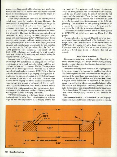
The preform was designed as a solid r<strong>in</strong>g (no teeth) with <strong>the</strong><br />
outer dimensious as dose as possible to <strong>the</strong> outer dimensions<br />
of <strong>the</strong> f<strong>in</strong>ished gear. This m<strong>in</strong>imlzes <strong>the</strong> amount of material<br />
to be moved dur<strong>in</strong>g forg<strong>in</strong>g, and this <strong>in</strong> turn, enhances die<br />
fiU<strong>in</strong>g.<br />
M<strong>in</strong>imize <strong>the</strong> Material Lost <strong>in</strong> <strong>the</strong> Rash. In steel forg<strong>in</strong>gs,<br />
approximately half of <strong>the</strong> cost of forg<strong>in</strong>g consists of material<br />
~----------------7~'--------------~~<br />
.260"R<br />
1. '"<br />
fIaure I<br />
...----------I.08O"'-----------...-t<br />
NOTE: R_III .37&" unl.. oth__ nobd.<br />
~~--------------------------a~'--------------------------~~


