

Gear Failure Analysis Involving Grinding Burn - Gear Technology ...
Gear Failure Analysis Involving Grinding Burn - Gear Technology ...
Gear Failure Analysis Involving Grinding Burn - Gear Technology ...

Create successful ePaper yourself
Turn your PDF publications into a flip-book with our unique Google optimized e-Paper software.
of the gear teeth showed no evi dence<br />
of distress.<br />
A detailed inspection was performed<br />
on all other parts of the gearbox.<br />
No other components showed<br />
any signs of degradation or indications<br />
of high load experience. The mating<br />
pinion gear showed no signs of surface<br />
distress or maldistributed load as shown<br />
in Figure 4.<br />
Magnetic particle inspection (MPI)<br />
was performed on the subject gear at the<br />
manufacturer. No cracks, in addition to<br />
those found visually, were found. No etch<br />
inspection was performed at this time to<br />
pre vent altering the crack surfaces, as<br />
the cracks were to be evaluated in detail<br />
as part of the destructive met allurgical<br />
investigation.<br />
Inspection of the pinion and subject<br />
gear tooth ge ometry was performed. The<br />
geometry of both members was within<br />
specification and was of high quality.<br />
Metallurgical Evaluation<br />
A photographic montage through<br />
the crack on tooth 6 (see Figure 3) is<br />
presented in Figure 5. The crack was<br />
approximately 0.103" long and 0.061"<br />
in depth. Several smaller cracks were<br />
observed branching from the main<br />
crack. The crack inter sected the surface<br />
at approximately 0.23" from the tooth<br />
tip.<br />
Figure 5 shows the crack trajectory<br />
to be inward from the tooth surface.<br />
<strong>Analysis</strong> will be presented in the later<br />
portion of this paper to bound the crack<br />
propagation path.<br />
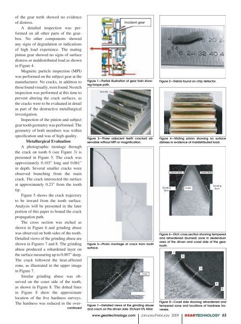
The cross section was etched as<br />
shown in Figure 6 and grinding abuse<br />
was observed on both sides of the tooth.<br />
Detailed views of the grinding abuse are<br />
shown in Figures 7 and 8. The grinding<br />
abuse pro duced a rehardened layer on<br />
the surface measuring up to 0.007" deep.<br />
The crack followed the heat-affected<br />
zone, as illustrated in the upper image<br />
in Figure 7.<br />
Similar grinding abuse was observed<br />
on the coast side of the tooth,<br />
as shown in Figure 8. The dotted lines<br />
in Figure 8 show the approximate<br />
location of the five hardness surveys.<br />
The hardness was re duced in the overcontinued<br />
Incident gear<br />
Figure 1—Partial illustration of gear train showing<br />
torque path.<br />
Figure 3—Three adjacent teeth cracked observable<br />
without MPI or magnification.<br />
Figure 5—Photo montage of crack from tooth<br />
surface.<br />
Crack<br />
Figure 7—Detailed views of the grinding abuse<br />
and crack on the driven side. Etchant 5% Nital.<br />
Figure 2—Debris found on chip detector.<br />
Figure 4—Mating pinion showing no surface<br />
distress or evidence of maldistributed load.<br />
<strong>Grinding</strong><br />
<strong>Burn</strong><br />
Driven Side<br />
Coast Side<br />
www.geartechnology.com January/February 2009 GEARTECHNOLOGY 63 00<br />
Crack<br />
<strong>Grinding</strong><br />
<strong>Burn</strong><br />
Figure 6—Etch cross section showing tempered<br />
and rehardened (burned) zone in dedendum<br />
area of the driven and coast side of the gear<br />
tooth.<br />
1<br />
2<br />
Figure 8—Coast side showing rehardened and<br />
tempered zone and locations of hardness traverses.<br />
3<br />
4<br />
5


