Installation Instruction Manual
Installation Instruction Manual
Installation Instruction Manual

Create successful ePaper yourself
Turn your PDF publications into a flip-book with our unique Google optimized e-Paper software.
P727EI-01<br />
8 ZONE SECURITY CONTROL PANEL<br />
<strong>Installation</strong> <strong>Instruction</strong> <strong>Manual</strong><br />
Software Version 3.3<br />
BASIC INSTALLATION<br />
Be sure to select a control panel installation site that is not easily<br />
accessible to intruders. Leave at least 2" around the panel box to permit<br />
adequate ventilation/heat dissipation. The installation location should<br />
be dry, in close proximity to an AC source and a ground connection.<br />
The printed circuit board, mounting hardware and keypad should be<br />
removed from the packaging inside panel box. Press the four white<br />
nylon mounting studs into cabinet from the back prior to mounting<br />
the cabinet. Before mounting the circuit board on the back of the<br />
cabinet, pull all cables into cabinet and prepare them for connection.<br />
Then attach circuit board to mounting studs. Connect all zones with<br />
the 1KOHM EOL resistors supplied, including keypad zone 8.<br />
Panel Hook-up Procedures<br />
All panel wiring must be completed before connecting transformer or<br />
battery. Install keypads and connect wires to keypad terminals on<br />
panel. Bell or siren should be connected to "Bell+" and "Bell-" terminals.<br />
Ensure correct polarity connection of sirens and polarized bells.<br />
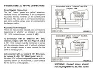
TERMINAL CONNECTIONS<br />
AC Terminals<br />
Use a 16VAC transformer with a minimum 40VA rating to provide<br />
sufficient AC power. Do not utilize any switch-controlled outlets to<br />
power the transformer.<br />
Siren/Bell Terminals (Bell +, Bell -)<br />
Bells or other warning devices requiring a steady voltage output<br />
during alarms are powered by the bell relay and the bell output<br />
(fused at 3A). Connect the positive lead to the "Bell+" terminal and<br />
the negative lead to relay input "NO" or "NC". Also connect a wire<br />
between Relay C terminal and "Aux-" terminal.<br />
Auxiliary Power Terminals<br />
Motion detectors and other security devices requiring 12VDC voltage<br />
can be powered by the auxiliary power supply. A maximum of<br />
400mA 12VDC is available from the AUX+ and AUX- terminals when<br />
only one keypad is used with the Esprit. For each additional keypad<br />
the auxiliary supply must be reduced by 20mA. The auxiliary supply<br />
is fused at 1 amp.<br />
Keypad Terminal (RED, BLACK, YELLOW, GREEN)<br />
Each keypad has connectors for four colored leads; red, black,<br />
yellow and green. Connect the lead to the corresponding colour input<br />
terminal on the control panel and the keypad. Mount keypads near<br />
entry/exit doors to shorten entry/exit delay intervals. If keypad zone 8<br />
is to be used, connect it to the keypad with a 1KOHM EOL resistor. If<br />
not, connect a 1KOHM EOL resistor in parallel to zone terminals on<br />
keypad. Up to 5 keypads can be connected in parallel.<br />
Please note: The keypad zone can be connected on all keypads<br />
installed. However, any open keypad zones will always be indicated<br />
as zone 8 on every keypad display. However, when keypad zone<br />
supervision is enabled, only the zone that is supervised indicates a<br />
zone 8 on every keypad. The keypad zone is always a delay zone.<br />
jumper any unused loops with the EOL resistors supplied. An open<br />
contact across the resistor or reduced loop resistance in fire zone 7<br />
will engage a pulse bell/siren.<br />
POWERING UP THE UNIT<br />
When keypads are installed far from the control panel, we<br />
recommend that you temporarily connect a keypad close to the<br />
panel to conduct "power-up" testing. If key switches are being<br />
installed, a keypad must be used to conduct programming.<br />
Connect the transformer. After 5 seconds, you can begin testing the<br />
unit. Enter random commands on the keypad. It should "beep" in<br />
response to these commands.<br />
Open a zone (except a keypad zone) to ensure that keypad and<br />
panel are responding to signals. If the keypad does not respond and<br />
if no indicator lights illuminate check for AC voltage at the "AC"<br />
terminals. If 16VAC is flowing, then keypad wiring should be verified,<br />
as well as the keypad/aux. supply fuse. If this fuse has blown, check<br />
for a short between black and red keypad wires before replacing it.<br />
Battery Hook-up<br />
Warning: Never connect the transformer or the battery until all wiring<br />
has been completed. Use a 12VDC, 6.5 AH gel cell<br />
battery. The red battery lead should be connected to the positive<br />
battery terminal, and the black battery lead to the negative battery<br />
terminal. Reversed connections will blow the battery fuse. The<br />
battery should not be connected until AC connections to the panel<br />
have been made. A "trouble" key indicator will illuminate on the<br />
keypad if AC power is turned off and battery is connected.<br />
SYSTEM STATUS COMMUNICATION:<br />
Every time a key is pressed, it illuminates and the keypad beeps to<br />
show an entry has been recognized. There are two types of beep<br />
tones which communicate information regarding keypad entries to<br />
the system user.<br />
"CONFIRMATION" beep:<br />
If an operation (ie. arming/disarming, programming) is correctly<br />
entered on the keypad, or the system switches to a new<br />
status/mode, the sounder emits an intermittent beep tone.<br />
"END/REJECTION" beep:<br />
If the system reverts to previous status, or an operation is incorrectly<br />
entered on the keypad, sounder emits a continuous beep tone.<br />
PROGRAMMING THE ESPRIT 727<br />
Esprit system programming is performed from the keypad. The<br />
system contains programmable memory (EEPROM) which does not<br />
erase, even after total battery and AC loss. System automatically<br />
reverts to "pre-power failure" status once battery/AC power are<br />
restored. Please note: If system was "armed" prior to AC/battery<br />
failure, it reverts to "armed" status approx. 2 minutes after power is<br />
restored, to allow motion detectors sufficient time to warm up.<br />
Zone Input Terminals (z1 to z6, fire zone 7, keypad zone 8)<br />
Zone terminals are the loop inputs for 6 fully-programmable zones.<br />
Connect normally closed detectors or contacts to each zone and<br />
1<br />
All programming pertaining to panel operation is stored in EEPROM<br />
sector which can only be accessed by entering the system installer<br />
code. With the exception of the factory-set installer code 0000 and
master code 0101, all other system features should be programmed.<br />
The installer code has access to all features programming but can't<br />
use any system functions (arming/disarming, bypassing, master and<br />
user codes programming). The factory-set installer code can be<br />
modified by following the instructions outlined in "Changing the<br />
installer code". If the new code is forgotten, the factory default code<br />
can be reset, unless the "installer code lock" has been enabled.<br />
When entering information on the keypad, pressing [CLEAR] erases<br />
the last keypad entries and returns panel to its previous status. If no<br />
key is pressed within 2 minutes, the unit automatically clears its<br />
memory and returns to normal status. Pressing [ENTER] accepts<br />
keyed-in data into memory.<br />
For all keypad/programming operations, key [10] represents "0".<br />
Installer code programming:<br />
To activate the programming mode for the first time, the factory<br />
default installer code must be entered on the keypad. To do so,<br />
press [ENTER], followed by the 4-digit default installer code 0000. The<br />
"ENTRY" beep will sound and the [ENTER] light will flash to indicate<br />
that the system is in programming mode, waiting for address entry.<br />
Changing the installer code: (address 00, 01, 02)<br />
The system default installer code contains four digits. (Based on<br />
your customers' requirements. It can also be modified to contain six<br />
digits.) While in programming mode, a new installer code can be<br />
created using the installer code memory address 00, 01 and 02. If<br />
the four digit default code length is to be used, "00" is the memory<br />
address corresponding to the 1st 2 digits of the new installer code<br />
and address 01 corresponds to the last two digits. The digits [0][0]<br />
([10][10]) can be then entered in the third memory address 02 so<br />
that code reset will not be necessary if the panel code length is<br />
switched back to 6 digits.<br />
Example: To change the system installer code 0000 to 9876:<br />
Enter programming mode. Press [ENTER]+[0][0] [0][0].<br />
"CONFIRMATION" beep sounds and [ENTER] key flashes, indicating that<br />
the panel is in "ENTER ADDRESS" mode. Press [0] + [0] (address<br />
for 1st 2 digits of new installer code). "CONF" beep will sound. [ENTER]<br />
will light up and remain on, indicating that the system is in "ENTER<br />
DATA" mode.<br />
Key in the first 2 digits of your new code. In this example: [9] + [8] +<br />
[ENTER]. "CONF" beep is heard. The system returns to "ENTER<br />
ADDRESS" mode, and the [ENTER] key flashes.<br />
Press [0] + [1] (address for last pair of digits of the new installer<br />
code). "CONF" beep follows, and the system is back in "ENTER<br />
DATA" mode. Key in the 3rd + 4th digits of your new code. In this<br />
example: [7] + [6] + [ENTER]. "CONF" beep sounds.<br />
Press [0] + [2] (address for mandatory pair of digits of the new<br />
installer code). "CONF" beep follows, and the system is back in<br />
"ENTER DATA" mode.<br />
Key in [0][0] + [ENTER]. "CONF" beep sounds.<br />
The installer code 9876 has been entered into memory. The system<br />
remains in programming mode, with the [ENTER] key flashing. (If a six<br />
digit installer code is required, same steps are followed, but the<br />
mandatory 00 digits are replaced by the third pair of digits of the six<br />
digit code.) More programming data can now be entered or<br />
programming mode can be exited by pressing [CLEAR]. After exiting<br />
programming mode, the "END/REJECTION" beep will sound.<br />
Restoring the factory default installer code:<br />
If a new installer code is lost or forgotten, the control panel can be<br />
returned to the factory-set default code by following these steps:<br />
(1) Remove AC and battery to power down the unit.<br />
(2) Connect a jumper between the EEPROM reset pins.<br />
(3) Connect AC or battery.<br />
(4) Wait for 5 seconds, then remove jumper.<br />
Default installer code has now been restored. All other programmed data<br />
remains the same. If an installer wishes to disable the factory default<br />
"reset" feature, this can be done by activating the "installer code lock".<br />
"Installer code lock": (address 37)<br />
The memory address for this feature is 37. In program mode, when<br />
address 37 is entered, the status of the "installer code lock" will be<br />
displayed on key [1]. The "installer code lock" function can be<br />
modified by selecting this key.<br />
Key [1]on:<br />
Key [1] off:<br />
System returns to default installer code upon reset<br />
Installer code locked. (will not revert to system default<br />
upon reset) Important: if the installer code lock is<br />
activated, and the new installer code is subsequently<br />
lost or forgotten, there is no way to return the system to<br />
programming mode. The panel must be returned to<br />
Paradox Security Systems for installer code reset.<br />
There isa charge for this service.<br />
Code Priority:<br />
There are several different types of system access codes and each has<br />
been assigned a priority which determines which system functions and<br />
features it can activate. Installer Code (Priority 1) can be use to program<br />
all system features but has no access to arming/disarming and access<br />
code programming. (This is the only code that can access installer code<br />
programming.) The Master User Code (priority 2) can arm/disarm the<br />
system (using all arming options), activate zone bypassing and<br />
reprogram master and user codes. User Codes 1-3 (priority 3) can be<br />
used to arm/disarm the system, activate "stay" and "away" arming, and<br />
zone bypassing. User Codes 4-6 (priority 4) can arm/disarm the system.<br />
User Code 7 (priority 5) is an "Arm only" access code.<br />
Master and User Code programming:<br />
To program the master and all user codes:<br />
Press [ENTER] + master code + 1 digit access code number + new 4<br />
or 6 digit code + [ENTER].<br />
Note: If only 2 or 4 digits are entered, digits "00" will be automatically<br />
enter in the remaining memory space.<br />
Master code:<br />
User code 1:<br />
User code 2:<br />
User code 3:<br />
User code 4:<br />
User code 5:<br />
User code 6:<br />
User code 7:<br />
[1] Arm, disarm, bypass, away, stay, reprogram<br />
master and user codes (default/reset code 010101)<br />
[2] Arm, disarm, bypass, away, stay<br />
[3] Arm, disarm, bypass, away, stay<br />
[4] Arm, disarm, bypass, away, stay<br />
[5] Arm, disarm<br />
[6] Arm, disarm<br />
[7] Arm, disarm<br />
[8] Arm only<br />
"ARM ONLY" CODE: Can only be used to arm the system. No other<br />
system features can be accessed, and the system cannot be disarmed<br />
using the "Arm Only" code, unless it is used during the exit delay period.<br />
Deleting a user code: Pressing the [2ND] key, followed by [ENTER]<br />
while in any user code address, will delete that user code.<br />
Exit delay/entry delay/alarm duration programming:<br />
The memory addresses for exit and entry delay, and alarm duration are:<br />
"27" exit (00-99seconds) "28" entry (00-99 seconds)<br />
"29" alarm (00-99 minutes)<br />
2
PROGRAMMABLE OUTPUTS: (address 30)<br />
The memory address for programmable output options is 30. The<br />
next two digits entered assign the conditions which cause PGM<br />
output to ground. The first digit entered corresponds to PGM 1, and<br />
the second digit to PGM 2.<br />
1ST DIGIT<br />
PGM1 GROUNDS ON:<br />
2ND DIGIT<br />
PGM 2 GROUNDS ON:<br />
0 EXIT DELAY 0 EXIT DELAY<br />
1 ARMED 1 ARMED<br />
2 READY 2 READY<br />
3 [2ND] KEY "ON" 3 [2ND] KEY "ON"<br />
4 FIRE 4 FIRE<br />
5 ALARM 5 ALARM<br />
6 STROBE (from alarm to disarm) 6 STROBE (from alarm to disarm)<br />
7 ENTRY + EXIT + ALARM 7 ENTRY + EXIT + ALARM<br />
8 EXIT + ARMED 8 ENTRY + ALARM<br />
9 NORMAL ARMING only 9 ENTRY+ ALARM<br />
*Energy saving option: PGM 1 will be activated by all arming options except "STAY" arming.<br />
Can lower thermostats, turn off lighting or appliances when leaving the premises.<br />
"Bypass enable" definition: (address 31)<br />
The memory address for "bypass enable" definition is 31. "Bypass<br />
enabling" identifies the zones that can potentially be bypassed during<br />
manual bypass arming, "AWAY" arming and "STAY" arming. (Fire zone<br />
7 cannot be bypass-enabled, and zone 8 is always bypass-enabled.) If<br />
a zone light is switched "on" during "bypass enable" definition, it will be<br />
possible to bypass this zone during all bypass operations. If the<br />
installation contains any zones that should never be bypassed, their<br />
zone light must be extinguished during "bypass enable" definition.<br />
Example: To "bypass enable" zones 1 and 3:<br />
Enter programming mode: ([ENTER] + installer code, "CONF" beep<br />
sounds, and [ENTER] key flashes.)<br />
Key in "bypass enable" memory address 31, [ENTER] stays on. Press<br />
on keys [1] and [3] to illuminate them. Turn off other zone lights (if<br />
any) to de-activate the "bypass-enable" definition. Press [CLEAR] to<br />
reject any incorrect data entries. Press [ENTER] to store data in<br />
memory. Enter another memory address to continue programming,<br />
or press [CLEAR] (or [ENTER]) to exit programming.<br />
Programming 24 hour zones: (address 32)<br />
Any zones illuminated at address 32 are defined "24 hour" and will<br />
generate alarms whenever the zone is open, regardless of whether<br />
the system is armed. "24 hour" zone definition takes priority over any<br />
other zone definition programming.<br />
"Delay/Instant" zone definition: (address 33)<br />
At memory address 33, if a zone light is turned "on", that zone is<br />
designated "instant" while the system is armed and will activate an<br />
alarm immediately with no entry delay. Any zones which are not "on"<br />
will be defined as "delay" zones, and will allow a zone entry delay<br />
period while the system is armed. (Zone entry delay time is<br />
programmable at address 28.) Fire zone 7 cannot be defined as a<br />
"delay" zone, and zone 8’s definition is always "delay".<br />
"Follow"zone definition: (address 34)<br />
A "follow" zone is an "instant" zone that switches to "delay" when the<br />
727 is in entry delay.<br />
"Stay" zone definition: (address 35)<br />
At address 35, select zones to be bypassed when the "stay-arming"<br />
feature is activated. Zones selected (illuminated keys) will not be<br />
armed when the "stay-arming" feature is chosen. If no zones are<br />
selected after address 35 is entered, all zones will be armed when<br />
"stay-arming" is enabled from the keypad. Please note that any<br />
zones that are to be defined as "stay" zones must first be "bypass<br />
enabled" (address 31) Zone 7 and 8 cannot be "stay" zones.<br />
SYSTEM OPTIONS 1: (address 36)<br />
The memory address for these features is 36. In system option<br />
programming, the "on" or "off" status of keys 1-5 determines which<br />
features are activated. If the wrong key is selected, press the same<br />
key again to cancel the entry. Once the required features are<br />
selected, press [ENTER] to store data in memory.<br />
Zones "fast" (all - except zone 8) Key [1] "off"<br />
(fast zones = immediate detection)<br />
Zones "slow" (all)<br />
Key [1] "on"<br />
Keyswitch operation disabled<br />
Keyswitch operation enabled<br />
Key [2] "off"<br />
Key [2] "on"<br />
Keyswitch/key[10] "regular" arming/disarming Key [3] "off"<br />
Keyswitch/key[10] "stay" arming<br />
Key [3] "on"<br />
(upon alarm, system disarming with code/keypad only.)<br />
6-digit access codes<br />
**4-digitaccess code<br />
Fast armKey [10] disabled<br />
Fast armKey [10] enabled<br />
Panic zone disabled<br />
Panic zone enabled (keys [1] + [3])<br />
Key [4] "off"<br />
Key [4] "on"<br />
Key [5] "off"<br />
Key [5] "on"<br />
Key [6] "off"<br />
Key [6] "on"<br />
*Slow zones: system waits until a zone has been open continuously<br />
for a minimum of 200 milliseconds before communicating "open<br />
zone" status, to reduce risk of false alarms.<br />
Fast zones = 20 milliseconds<br />
**4-digit vs 6 digit access code programming<br />
The default system installer and master codes contain four digits.<br />
When changing the installer code, or creating new master or user<br />
codes, all codes must be programmed to contain 4 digits.<br />
SYSTEM OPTIONS 2: (address 37)<br />
Installer code lock:<br />
Key [1] "off": System returns to default installer upon reset.<br />
Key [1] "on": Installer code locked. (see p.2 for information)<br />
Keypad supervision:<br />
Key [2] "on": Keypad supervision enabled.<br />
Key [2] "off": Keypad supervision disabled.<br />
Relay output:<br />
Key [5] "on": Relay output is energized upon alarm only.<br />
Key [5] "off": Relay output is de-energized upon alarm and<br />
energized when the 727 is not in alarm ("fail safe")<br />
(The fire alarm will generate an intermittent alarm<br />
signal in both cases.)<br />
Fire / 24 hour zone:<br />
Key [6] "on": Zone 7 is defined as a fire zone.<br />
Key [6] "off": Zone 7 is defined as a 24 hour zone.<br />
SYSTEM ARMING OPTIONS<br />
REGULAR SYSTEM ARMING<br />
The system can only be armed if the green "READY" light comes on.<br />
The "READY" indicator will only illuminate if all zones are closed. This<br />
means all door/window contacts must be closed, and movement in<br />
motion detector-protected areas must be stopped. When the "READY"<br />
light illuminates, enter a pre-programmed six or four-digit user code.<br />
Upon entry of a complete, correct access code, the red "ARMED" light<br />
will illuminate, followed by the keypad "CONF" beep. (If the access<br />
code is entered incorrectly, the "END/REJ" beep will sound. If an<br />
incorrect entry is made at any time, press [CLEAR] and re-enter the<br />
data.) The green "READY" light will flash for the period of the exit<br />
3
delay. (Please note: This is the sole system function that an "arm<br />
only" code can activate. An "arm only" code will not give a system<br />
user access to any of the functions listed below.)<br />
STAY ARMING [STAY] + ACCESS CODE (PRIORITY 2, 3)<br />
This feature allows the end user to partially arm the system, while<br />
remaining in the protected area. Entering [STAY] + access code on<br />
the keypad activates the "stay arming" command. Zones to be<br />
bypassed in ‘stay arming” mode must be selected by the installer<br />
during "stay" zone definition, and must also be designated as<br />
"bypass enabled". The system will not arm if any open zones have<br />
not previously been defined as “stay” zones. The fire zone cannot be<br />
programmed as a "STAY" zone. If an alarm is generated, or a zone<br />
that was not designated as a "stay" zone is opened while the system<br />
is armed, system reset can only be activated from a keypad and not<br />
with a key switch/push button.<br />
FAST ARMING KEY [10]<br />
Fast arming (regular mode) is enabled at address 36. If activated,<br />
when the "READY" light is on, pressing key [10] for 2 seconds<br />
automatically arms the system. There's no need to enter an access<br />
code. This feature can be used to permit selected individuals (i.e.<br />
maintenance workers, repair personnel) to arm the system when<br />
leaving the protected area.<br />
Fast arming (stay mode) is enabled at address 36. When activated,<br />
no "READY" light is required to arm the system. Pressing key [10] for<br />
2 seconds automatically "STAY" arms the system. (See "STAY" arming<br />
features described above.) Also, when system is stay armed,<br />
pressing key [10] will activate an exit delay and then return the<br />
system to STAY ARM status, eliminating the need to disarm and then<br />
STAY ARM the system again.<br />
MANUAL BYPASS ARMING [BYP]+ ACCESS CODE (PRIORITY2, 3)<br />
Bypassed zones will not generate an alarm and are not displayed on<br />
the keypad. <strong>Manual</strong> bypass arming is employed when the system<br />
user chooses not to arm the entire protected area. Only zones that<br />
have been defined as "bypass enabled" (address 31) can be selected<br />
during manual bypass arming. (Zone 8 is always bypass-enabled.)<br />
The user manually selects specific zones that will not be armed, rather<br />
than bypassing the zones defined by the installer as part of the "stayarming"<br />
feature. Defective zones can also be temporarily bypassed<br />
until repairs are made, so that the system can still be armed.<br />
To bypass zones, enter [BYP] + a valid access code. [BYP] and<br />
[ENTER] keys will illuminate. (Zone bypassing can only be accessed<br />
by the master user code, and user codes 1-3.). Zone numbers to be<br />
bypassed (1,2,3,4,5,6) should be keyed in. When a zone light is on,<br />
it indicates a zone that will be bypassed. Pressing [CLEAR] erases all<br />
bypass entries. Zones to be bypassed should then be re-entered.<br />
(Pressing [CLEAR] again will exit the bypass mode without saving any<br />
bypass information in memory.) If bypass information is correct,<br />
press [ENTER] to end and save bypass function being programmed.<br />
[BYP] light will remain illuminated, indicating that zones have been<br />
bypassed. To cancel the zone bypass "status" just entered, press<br />
[BYP] + user code + [CLEAR] + [ENTER]. Zone bypasses are<br />
automatically cancelled every time the system is disarmed.<br />
"AWAY" AUTO BYPASS ARMING [AWAY] + ACCESS CODE (PRIORITY 2, 3)<br />
System users wishing to arm the system rapidly without manually<br />
entering zones to be bypassed, can make use of the "Away" autobypass<br />
feature. [AWAY] + access code should be keyed in. (The "READY"<br />
light does not have to be on, but all open zones must be "bypassenabled".)<br />
Once the exit delay expires, any open zones will<br />
automatically be bypassed and the system will be armed. (The fire zone<br />
cannot be bypassed.) If any zones have been left open, the [BYP] light<br />
will illuminate to indicate that zones have automatically been bypassed.<br />
Please note: This feature is not recommended for regular use because<br />
bypassing zones can reduce the efficiency of system protection.<br />
KEY SWITCH ARMING/DISARMING<br />
To provide one button system arming/disarming, key switch operation<br />
must be enabled (Refer to "System Options"). The key switch should<br />
be connected, and a “push” button connected in place of a keypad.<br />
The panel can be programmed to activate "regular" or "stay" arming<br />
from the key switch/push button. If "READY" and "ARMED" LED status<br />
indicators are required, LEDs can be connected to the 2 PGM outputs.<br />
The two programmable outputs should then be set as follows: (please<br />
refer to "Programmable Output Options" for further explanation.)<br />
1) PGM 1 should be programmed to indicate "EXIT + ARMED" status<br />
(Option #8, PGM 1)<br />
2) PGM 2 should be programmed to indicate "READY" status<br />
(Option #2, PGM 2)<br />
If a buzzer is required for the entry delay, Option #8 (ENTRY + ALARM)<br />
should be programmed for PGM2.<br />
SYSTEM DISARMING<br />
Enter the protected area using the designated entry-exit door. The<br />
keypad sounder will beep to remind user to disarm system. Key in<br />
the 6 or 4-digit access code on the keypad, before the allotted entry<br />
time expires. If the access code is entered incorrectly, press [CLEAR]<br />
and re-enter it. The "ARMED" light will extinguish and the sounder will<br />
change to the "CONF" beep before silencing.<br />
ALARM MEMORY [MEM]<br />
When disarming the system (or resetting the alarm), the memory<br />
light [MEM] will illuminate if any alarm situations took place during the<br />
preceding armed period. A record of all alarm situations that<br />
occurred while the system was armed is stored in memory. After<br />
disarming the system, pressing once on the [MEM] key brings up the<br />
last "alarm event", which is displayed on the keypad.<br />
Up to 15 levels of alarm history can be stored in memory, and are<br />
retrieved by repeated pressing of the [MEM] key. When the final entry<br />
is reached, the "END/REJ" beep is heard and the [MEM] light<br />
extinguishes. This indicates that maximum level of alarm history has<br />
been reached. To review alarm history again, press [MEM]. The last<br />
15 events are stored in memory. When the memory is full, the<br />
newest event takes the place of the oldest one in memory. After<br />
pressing of the [MEM] key, events will be displayed in order from the<br />
most recent to the oldest. The memory will not clear upon arming.<br />
Exiting memory mode at any level is achieved by pressing [CLEAR],<br />
which will be followed by the "END/REJ"beep. The [MEM] key will also<br />
extinguish. (The system will exit memory mode automatically<br />
following display of the last alarm event.)<br />
Bypass recall:This feature permits the system users to reinstate<br />
latest zone bypass instructions saved in memory. By pressing [BYP]<br />
while in bypass programming mode, previous bypass status is reestablished.<br />
Even if user is in process of entering new bypass<br />
information on keypad, one touch of [BYP] key overrides new<br />
information and reinstates the preceding zone bypass instructions<br />
saved. Reminder: The fire zone cannot be bypassed.<br />
4<br />
SYSTEM ALARMS:<br />
General alarms:<br />
Important: In the event of a burglar alarm, the alarm output<br />
generates a continuous alarm signal to activate a siren driver. To<br />
stop the alarm signal, enter a valid disarming code. The "CONF" beep<br />
will be heard, and the alarm signal (and siren) will cease. If the<br />
system was armed, it will also automatically disarm. If the alarm is<br />
generated in a 24 hour zone, the siren will be silenced for 30<br />
seconds when a valid access code is entered. After this 30 second<br />
period, if the 24 hour zone is still open, the siren will re-activate.
If no valid access code is entered, the siren will automatically shut off<br />
after a pre-programmed time period elapses. (See "PROGRAMMING<br />
REFERENCE" section: "alarm duration".) However, if a protected<br />
zone is still open, the alarm will immediately resume.<br />
Fire alarms: (Zone 7)<br />
During a fire alarm, the alarm output generates an intermittent alarm<br />
signal. Fire alarm reset conditions are the same as 24 hour zone<br />
reset. The fire alarm siren will shut off automatically after the<br />
programmed alarm duration time. Fire alarm will be recorded in<br />
memory and displayed as zone 7.<br />
Panic alarms:<br />
Pressing keys [1] and [3] simultaneously for 1 second generates a<br />
panic alarm. Panic alarms will be recorded in memory but will not be<br />
displayed on the keypad.<br />
TROUBLE DISPLAY [TRBL]<br />
AC power failure is communicated to the system user by the<br />
illumination of the keypad [TRBL] indicator.<br />
KEYPAD ILLUMINATION LEVEL ADJUSTMENT<br />
Pressing on the [MEM] key for 2 seconds changes it to a keypad<br />
illumination "hot" key. A change in keypad illumination will be<br />
apparent, and by pressing on the [MEM] key again, the level can be<br />
adjusted from low, medium to high, or turned off as required. After<br />
the desired level is selected, press [ENTER] or [CLEAR] to save the<br />
setting in the keypad memory.<br />
PROGRAMMING REFERENCE<br />
FUNCTION ADDRESS + DATA DEFAULT<br />
PRIORITY<br />
Installer code: 1 [0][0] [0][1] [0][2] 000000<br />
Master code: 2 [1] Arm, disarm, bypass, away, stay, 010101<br />
Master and User code programming<br />
User code 1: 3 [2] Arm, disarm, bypass, away, stay<br />
User code 2: 3 [3] Arm, disarm, bypass, away, stay<br />
User code 3: 3 [4] Arm, disarm, bypass, away, stay<br />
User code 4: 4 [5] Arm, disarm<br />
User code 5: 4 [6] Arm, disarm<br />
User code 6: 4 [7] Arm, disarm<br />
User code 7: 5 [8] Arm only<br />
KEYPAD SUPERVISION<br />
Keypad supervision, when enabled, allows the use of only one<br />
keypad zone. Any other keypad zone terminal must be shorted.<br />
If using a 616, 626, or 633 LED keypad with software version 3.9 or<br />
earlier, OR a PS1 version 1.1:<br />
• KEYPAD ZONE SUPERVISION FEATURE MUST BE"OFF".<br />
If using a 616, 626, or 633 LED keypad with software version 4.0<br />
onward, OR a PS1 version 2.0 onward:<br />
• KEYPAD ZONE SUPERVISION FEATURE MUST BE"ON".<br />
IMPORTANT: Although this control panel is compatible with most<br />
security products available, we highly recommend that the ESPRIT<br />
727 be used in combination with PARADOX motion and glassbreak<br />
detectors. This will ensure that your security system operates at<br />
maximum effectiveness.<br />
WARRANTY<br />
The Seller warrants its products to be free from defects in materials<br />
and workmanship under normal use for a period of one year. Except<br />
as specifically stated herein, all express or implied warranties<br />
whatsoever, statutory or otherwise, including without limitation, any<br />
implied warranty of merchantability and fitness for a particular<br />
purpose, are expressly excluded. Because Seller does not install or<br />
connect the products and because the products may be used in<br />
conjunction with products not manufactured by Seller. Seller cannot<br />
guarantee the performance of the security system. Seller obligation<br />
and liability under this warranty is expressly limited to repairing or<br />
replacing, at Seller's option, any product not meeting the<br />
specifications. In no event shall the Seller be liable to the buyer or any<br />
other person for any loss or damages whether direct or indirect or<br />
consequential or incidental, including without limitation, any damages<br />
for lost profits stolen goods, or claims by any other party, caused by<br />
defective goods or otherwise arising from the improper, incorrect or<br />
otherwise faulty installation or use of the merchandise sold.<br />
5