powerCONTROL PCI 0035 / PCI 0070 / PCI 0150
powerCONTROL PCI 0035 / PCI 0070 / PCI 0150
powerCONTROL PCI 0035 / PCI 0070 / PCI 0150

Create successful ePaper yourself
Turn your PDF publications into a flip-book with our unique Google optimized e-Paper software.
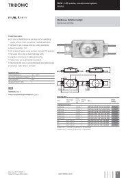
HI 35–150 W<br />
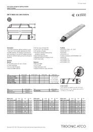
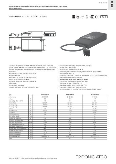
Digital electronic ballasts with lamp connection cable for remote mounted applications<br />
Metal halide lamps<br />
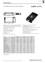
<strong>powerCONTROL</strong> <strong>PCI</strong> <strong>0035</strong> / <strong>PCI</strong> <strong>0070</strong> / <strong>PCI</strong> <strong>0150</strong><br />
RoHS<br />
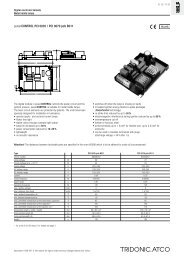
500<br />
L<br />
4,5<br />
d H<br />
B<br />
D<br />
The digital components in <strong>powerCONTROL</strong> control the power circuit and<br />
ignition. <strong>powerCONTROL</strong> is suitable for metal halide lamps. The basic circuit<br />
elements are patented. The ballasts were especially designed for mounted<br />
applications.<br />
• operate quartz- and ceramic burner lamps<br />
• flicker free light<br />
• stable colour through constant light output<br />
• lamp life increased up to 50 %<br />
• power consumption reduced by 10–20 %<br />
• lightweight<br />
• no acoustic resonance<br />
• switches off when the lamp is missing or faulty<br />
• increased ignition energy thanks to pulse packages<br />
(PulseControl technology)<br />
• re-strike time reduced by up to 50 %<br />
• electromagnetic interference during ignition reduced by up to 95 %<br />
• overtemperature cut off<br />
• screw terminals up to 1.5 mm 2 for flexible wire, up to 2.5 mm 2 for solid wire<br />
• mains-side through-wiring possible<br />
• halogen-free lamp cable with ST18 socket<br />
• can be used in movable luminaires with plugs<br />
(discharge voltage < 34 V after 1 s)<br />
• one-piece housing in black polyamide IP20<br />
• integrated terminal cover and cable clamp<br />
• no tools required for installing the terminal cover and cable clamps<br />
Type <strong>PCI</strong> <strong>0035</strong> B521 <strong>PCI</strong> <strong>0070</strong> B521 <strong>PCI</strong> <strong>0150</strong> B521<br />
article number 86458184 86458185 86458186<br />
wattage W 39 72 147<br />
total wattage at ta = 25 °C W 44 79 159<br />
mains voltage V 220–240 220–240 220–240<br />
AC voltage range V 198–254 198–254 198–254<br />
DC voltage range V 153–320 153–320 153–320<br />
current A 0.20 0.35 0.70<br />
mains frequency Hz 0/50/60 0/50/60 0/50/60<br />
power factor l 0.97 0.97 0.97<br />
operating frequency Hz 145 145 145<br />
max. ignition voltage kVp 5 5 5<br />
length of the lamp cable m 0.5 0.5 0.5<br />
connection type (lamp cable) ST ST ST<br />
max. cable length to lamp m/pF 3/240 3/240 3/240<br />
max. ambient temperature ta °C 50 50 45<br />
min. ambient temperature ta °C -25 -25 -25<br />
permissible housing temperature tc °C 65 75 75<br />
diameter of ceiling opening mm > 85 > 85 > 86<br />
fixing centres length (D) mm 127.6 127.6 187.6<br />
fixing centres width (d) mm 68.6 68.6 68.6<br />
length x width x height mm 150 x 79.5 x 34 150 x 79.5 x 34 210 x 79.5 x 35<br />
weight g 290 300 420<br />
Data sheet 05/08-475-5 We reserve the right to make technical changes without prior notice.
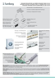
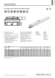
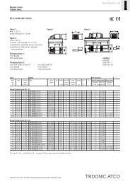
Digital electronic ballasts with lamp connection cable for remote mounted applications<br />
Metal halide lamps<br />
Installation instructions<br />
Wiring type and cross section<br />
Stranded wire with end ferrule with a cross section<br />
up to 1.5 mm 2 or solid wire up to 2.5 mm 2 may be<br />
used for wiring.<br />
max. ∅ = 9,7 mm 18<br />
min. ∅ = 6,3 mm 24<br />
Lamp cable connector<br />
Black ST-18 socket<br />
30<br />
24 6<br />
6<br />
0,5 – 2,5<br />
Radio interference<br />
• Do not cross mains and lamp cables.<br />
• Do not lay mains cables together with lamp<br />
cables (ideally they should be 5–10 cm apart).<br />
• Do not lead mains cables too closely along the<br />
electronic ballast.<br />
• Twist lamp cables.<br />
• Increase the distance between lamp cables<br />
and earthed metal surfaces.<br />
• Keep the mains cable short.<br />
• Parallel runs (x) of mains and lamp cables must<br />
be kept as short as possible.<br />
Important advise<br />
When a lamp is changed (at the end of its life),<br />
if a lamp is missing or after overtemperature<br />
shutdown the mains voltage of the ECG must be<br />
disconnected.<br />
Warning – starting voltage up to max. 5 kV!<br />
Not suitable for use with lamps with<br />
integral ignitors.<br />
Safety switch off<br />
End of life of the lamps<br />
At the end of their useful life, lamps often cycle<br />
on/off. The <strong>PCI</strong> ballast recognises this condition<br />
and switches off the lamp, after three complete<br />
on/off cycles and whilst the supply has been<br />
unswitched. Complete lamp switch off enables<br />
easy identification of a defective lamp in the<br />
application. After a change of the faulty lamp and<br />
an interruption of the mains supply (mains reset)<br />
the ballast will strike the lamp. When there is no<br />
lamp in circuit or a defective lamp is connected to<br />
the ballast, the ballast will switch off after apr. 25<br />
minutes (3.5 minutes of ignition time).<br />
Overtemperature shutdown<br />
The units shut down at Dt approx. +10 °C<br />
compared with tc/ta. A mains reset must be<br />
carried out so that the units switch on again.<br />
Overload strength<br />
320 VAC / 1 h<br />
Note on wiring<br />
The length of the lamp wires is limited by the<br />
value of cable capacitance. The maximum of<br />
240 pF would enable connection of approximately<br />
3 metres of lamp wire.<br />
In class 1 luminaires it is necessary to earth the<br />
ballast and the luminaire.<br />
Terminals<br />
Screw type M3<br />
Torque 0.5 Nm<br />
Packing quantities<br />
single pack<br />
box of 12<br />
24 boxes/pallet<br />
288 pieces/pallet<br />
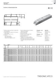
Fixing conditions<br />
Dry, acidfree, oilfree, fatfree. The maximum<br />
ambient temperature should not be exceeded.<br />
Is not suitable for fixing in corner.<br />
Leuchte<br />
Luminaire<br />
>100 mm<br />
>20 mm<br />
>50 mm<br />
If several ballasts are installed in masts, boxes,<br />
etc., measures must be taken to avoid overheating<br />
of individual components.<br />
Circuit diagram <strong>PCI</strong> class 1 applications<br />
Standards<br />
EN 55015 (radio interference)<br />
EN 61000-3-2 (mains harmonics)<br />
EN 61347-2-12<br />
EN 61547 (interference immunity)<br />
CE mark<br />
EMV-VDE mark<br />
ENEC mark<br />
Harmonic distortion in the mains supply<br />
Ballast<br />
Type THD 3 5 7 9 11<br />
<strong>PCI</strong> <strong>0035</strong> 7.2 3.9 3.8 2.4 3.0 1.7<br />
<strong>PCI</strong> <strong>0070</strong> 6.6 3.7 3.3 2.2 2.6 1.7<br />
<strong>PCI</strong> <strong>0150</strong> 7.5 3.9 4.4 1.7 2.0 0.7<br />
Ballast lumen factor<br />
EN 60929 8.1<br />
AC/DC-BLF<br />
Type U = 198–254 V, 25 °C<br />
<strong>PCI</strong> <strong>0035</strong> 1.00<br />
<strong>PCI</strong> <strong>0070</strong> 1.00<br />
<strong>PCI</strong> <strong>0150</strong> 1.00<br />
Loading of automatic circuit breakers<br />
Automatic circuit<br />
breaker type C10 C13 C16 C20 B10 B13 B16 B20<br />
Installation ∅ 1.5 mm 2 1.5 mm 2 1.5 mm 2 2.5 mm 2 1.5 mm 2 1.5 mm 2 1.5 mm 2 2.5 mm 2<br />
<strong>PCI</strong> <strong>0035</strong> 30 40 50 60 15 20 25 30<br />
<strong>PCI</strong> <strong>0070</strong> 14 25 36 42 8 14 18 18<br />
<strong>PCI</strong> <strong>0150</strong> 7 14 20 20 4 6 7 7<br />
Data sheet 05/08-475-5 We reserve the right to make technical changes without prior notice.