- Page 1:
Algorithms Copyright c○2006 S. Da
- Page 4 and 5:
4 Paths in graphs 109 4.1 Distances
- Page 7 and 8:
List of boxes Bases and logs . . .
- Page 9 and 10:
Preface This book evolved over the
- Page 11 and 12:
Chapter 0 Prologue Look around you.
- Page 13 and 14:
The first question is moot here, as
- Page 15 and 16:
for addition, which works on one di
- Page 17 and 18:
4. Likewise, any polynomial dominat
- Page 19:
and in general ( Fn ) = F n+1 ( ) n
- Page 22 and 23:
Bases and logs Naturally, there is
- Page 24 and 25:
Figure 1.1 Multiplication à la Fra
- Page 26 and 27:
Figure 1.3 Addition modulo 8. 6 0 0
- Page 28 and 29:
Figure 1.4 Modular exponentiation.
- Page 30 and 31:
Figure 1.6 A simple extension of Eu
- Page 32 and 33:
We say x is the multiplicative inve
- Page 34 and 35:
Figure 1.7 An algorithm for testing
- Page 36 and 37:
Figure 1.8 An algorithm for testing
- Page 38 and 39:
Randomized algorithms: a virtual ch
- Page 40 and 41:
Alice’s encryption function is th
- Page 42 and 43:
Figure 1.9 RSA. Bob chooses his pub
- Page 44 and 45:
There is nothing inherently wrong w
- Page 46 and 47:
Exercises 1.1. Show that in any bas
- Page 48 and 49:
the depth of the circuit or the lon
- Page 50 and 51:
(c) Give an example of positive int
- Page 52 and 53:
x = x L x R = 2 n/2 x L + x R y = y
- Page 54 and 55:
Figure 2.2 Divide-and-conquer integ
- Page 56 and 57:
Binary search The ultimate divide-a
- Page 59 and 60:
An n log n lower bound for sorting
- Page 61 and 62:
The three sublists S L , S v , and
- Page 63 and 64:
to be the best running time possibl
- Page 66 and 67:
qp t AB CD EF GH IJ KL MN OP QR Why
- Page 68 and 69:
The equivalence of the two polynomi
- Page 70 and 71:
Figure 2.6 The complex roots of uni
- Page 72 and 73:
A matrix reformulation To get a cle
- Page 74 and 75:
The orthogonality property can be s
- Page 76 and 77:
FFT n (input: a 0 , . . . , a n−1
- Page 78 and 79:
The slow spread of a fast algorithm
- Page 80 and 81:
(e) T (n) = 8T (n/2) + n 3 (f) T (n
- Page 82 and 83:
2.21. Mean and median. One of the m
- Page 84 and 85:
(c) In fact, squaring matrices is n
- Page 87 and 88:
Chapter 3 Decompositions of graphs
- Page 89 and 90:
Therefore, each edge appears in exa
- Page 91 and 92:
Figure 3.3. 1 The previsit and post
- Page 93 and 94:
Figure 3.6 (a) A 12-node graph. (b)
- Page 95 and 96:
Tree edges are actually part of the
- Page 97 and 98:
the same thing. Since a dag is line
- Page 99 and 100:
Figure 3.10 The reverse of the grap
- Page 101 and 102:
Exercises 3.1. Perform a depth-firs
- Page 103 and 104:
(a) Model this as a graph problem:
- Page 105 and 106:
For instance, in the graph below (w
- Page 107 and 108:
3.30. On page 97, we defined the bi
- Page 109 and 110:
Chapter 4 Paths in graphs 4.1 Dista
- Page 111 and 112:
Figure 4.4 The result of breadth-fi
- Page 113 and 114:
Figure 4.6 Breaking edges into unit
- Page 115 and 116:
into account. This viewpoint gives
- Page 117 and 118:
§¦ ¥¤ £¢ ©¨ #"
- Page 119 and 120:
Which heap is best? The running tim
- Page 121 and 122:
Figure 4.11 (a) A binary heap with
- Page 123 and 124:
Figure 4.13 The Bellman-Ford algori
- Page 125 and 126:
Figure 4.15 A single-source shortes
- Page 127 and 128:
Input: Undirected graph G = (V, E)
- Page 129 and 130:
4.16. Section 4.5.2 describes a way
- Page 131 and 132:
Let r ∗ be the maximum ratio achi
- Page 133 and 134:
Chapter 5 Greedy algorithms A game
- Page 135 and 136:
Trees A tree is an undirected graph
- Page 137 and 138:
Figure 5.3 The cut property at work
- Page 139 and 140:
eturn x As can be expected, makeset
- Page 141 and 142:
Figure 5.7 The effect of path compr
- Page 143 and 144:
A randomized algorithm for minimum
- Page 145 and 146:
Figure 5.9 Top: Prim’s minimum sp
- Page 147 and 148:
Figure 5.10 A prefix-free encoding.
- Page 149 and 150:
149
- Page 151 and 152:
5.3 Horn formulas In order to displ
- Page 153 and 154:
Figure 5.11 (a) Eleven towns. (b) T
- Page 155 and 156:
Exercises 5.1. Consider the followi
- Page 157 and 158:
(a) Code: {0, 10, 11} (b) Code: {0,
- Page 159 and 160:
Input: Undirected graph G = (V, E);
- Page 161 and 162:
Chapter 6 Dynamic programming In th
- Page 163 and 164:
Figure 6.2 The dag of increasing su
- Page 165 and 166:
Programming? The origin of the term
- Page 167 and 168:
Figure 6.4 (a) The table of subprob
- Page 169 and 170:
Common subproblems Finding the righ
- Page 171 and 172:
6.4 Knapsack During a robbery, a bu
- Page 173 and 174:
Memoization In dynamic programming,
- Page 175 and 176:
Figure 6.7 (a) ((A × B) × C) × D
- Page 177 and 178:
ecause it leads right back to the O
- Page 179 and 180:
d ij . We must pick the best such i
- Page 181 and 182:
Figure 6.11 I(u) is the size of the
- Page 183 and 184:
6.8. Given two strings x = x 1 x 2
- Page 185 and 186:
Figure 6.12 Two binary search trees
- Page 187 and 188:
6.26. Sequence alignment. When a ne
- Page 189 and 190:
Chapter 7 Linear programming and re
- Page 191 and 192:
It is a general rule of linear prog
- Page 193 and 194:
the feasible region. The point of f
- Page 195 and 196:
Figure 7.3 A communications network
- Page 197 and 198:
Reductions Sometimes a computationa
- Page 199 and 200:
Matrix-vector notation A linear fun
- Page 201 and 202:
Figure 7.5 An illustration of the m
- Page 203 and 204:
L e R s t e ′ We claim that size(
- Page 205 and 206:
Figure 7.6 Continued Current Flow R
- Page 207 and 208:
from the algorithm, which in such c
- Page 209 and 210:
Figure 7.10 A generic primal LP in
- Page 211 and 212:
Now suppose the two of them play th
- Page 213 and 214:
In LP form, this is min w −3y 1 +
- Page 215 and 216:
7.6.2 The algorithm On each iterati
- Page 217 and 218:
Figure 7.13 Simplex in action. Init
- Page 219 and 220:
close to one another? Unboundedness
- Page 221 and 222:
Gaussian elimination Under our alge
- Page 223 and 224:
output AND NOT OR AND OR NOT true f
- Page 225 and 226:
Exercises 7.1. Consider the followi
- Page 227 and 228:
7.12. For the linear program max x
- Page 229 and 230:
• f (i) is a valid flow from s i
- Page 231 and 232:
7.28. A linear program for shortest
- Page 233 and 234:
Chapter 8 NP-complete problems 8.1
- Page 235 and 236:
Satisfiability SATISFIABILITY, or S
- Page 237 and 238:
cost as the budget. Fine, but how d
- Page 239 and 240:
Figure 8.3 What is the smallest cut
- Page 241 and 242:
Figure 8.4 A more elaborate matchma
- Page 243 and 244:
8.2 NP-complete problems Hard probl
- Page 245 and 246:
I. These two translation procedures
- Page 247 and 248:
Figure 8.7 Reductions between searc
- Page 249 and 250:
Figure 8.8 The graph corresponding
- Page 251 and 252:
Figure 8.9 S is a vertex cover if a
- Page 253 and 254:
2n − m pets will be left unmatche
- Page 255 and 256: Figure 8.10 Rudrata cycle with pair
- Page 257 and 258: est of the graph as shown in Figure
- Page 259 and 260: RUDRATA CYCLE−→TSP Given a grap
- Page 261 and 262: Now that we know CIRCUIT SAT reduce
- Page 263 and 264: Exercises 8.1. Optimization versus
- Page 265 and 266: Input: An undirected graph G = (V,
- Page 267 and 268: • (w i , w i ′ ) for all i = 1,
- Page 269 and 270: Chapter 9 Coping with NP-completene
- Page 271 and 272: anching. We can expand either of th
- Page 273 and 274: follow the same pattern. As before,
- Page 275 and 276: 9.2 Approximation algorithms In an
- Page 277 and 278: 2. It can be used to build a vertex
- Page 279 and 280: 9.2.3 TSP The triangle inequality p
- Page 281 and 282: Let’s consider the O(nV ) algorit
- Page 283 and 284: iterations will be needed: whether
- Page 285 and 286: Figure 9.8 Local search. Figure 9.7
- Page 287 and 288: What can be done about such subopti
- Page 289 and 290: Figure 9.10 The search space for a
- Page 291 and 292: Exercises 9.1. In the backtracking
- Page 293 and 294: start with any S ⊆ V while there
- Page 295 and 296: Chapter 10 Quantum algorithms This
- Page 297 and 298: Figure 10.2 Measurement of a superp
- Page 299 and 300: Figure 10.3 A quantum algorithm tak
- Page 301 and 302: ¡ £¢ ¥¤ §¦ ©¨ #" %
- Page 303 and 304: The Fourier transform of a periodic
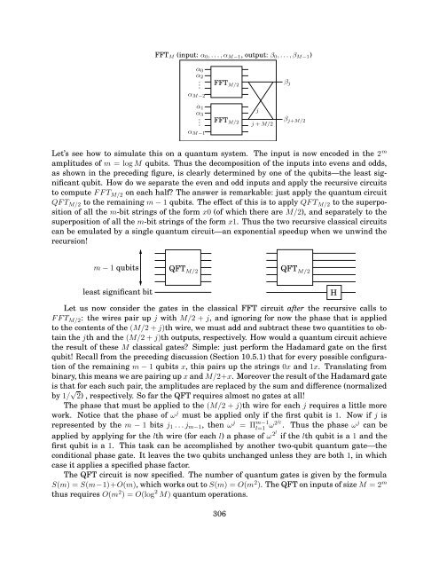
- Page 305: Yet another basic gate, the control
- Page 309 and 310: Figure 10.6 Quantum factoring. 0 QF
- Page 311 and 312: Exercises 10.1. ∣ ψ 〉 = 1 √2
- Page 313 and 314: Historical notes and further readin
- Page 315 and 316: Index O(·), 13 Ω(·), 14 Θ(·),
- Page 317 and 318: interior-point method, 217 interpol