
You also want an ePaper? Increase the reach of your titles
YUMPU automatically turns print PDFs into web optimized ePapers that Google loves.
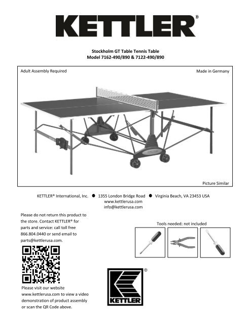
Stockholm GT Table Tennis Table<br />
Model 7162-490/890 & 7122-490/890<br />
Adult <strong>Assembly</strong> Required<br />
Made in Germany<br />
Picture Similar<br />
KETTLER® International, Inc. 1355 London Bridge Road Virginia Beach, VA 23453 <strong>USA</strong><br />
www.kettlerusa.com<br />
info@kettlerusa.com<br />
Please do not return this product to<br />
the store. Contact KETTLER® for<br />
parts and service: call toll free<br />
866.804.0440 or send email to<br />
parts@kettlerusa.com.<br />
Tools needed; not included<br />
Please visit our website<br />
www.kettlerusa.com to view a video<br />
demonstration of product assembly<br />
or scan the QR Code above.
Before <strong>Assembly</strong><br />
Before assembling or using the table tennis table, please read the following instructions carefully. They contain important information for<br />
use and maintenance of the equipment as well as for your personal safety. Keep these instructions in a safe place for maintenance<br />
purposes or for ordering spare parts.<br />
All KETTLER ® products are designed in accordance with the latest safety regulations and undergo a constant process of quality<br />
control during manufacturing. The knowledge gained in this process is used to constantly improve and develop our products. In<br />
order to offer our customers the very best in product quality, we reserve the right to make technical changes at any time. In spite<br />
of this, should you have any cause for complaint, please contact KETTLER ® .<br />
Note on Safety<br />
The table tennis table should be used only for its<br />
intended purpose, i.e. for playing with suitable table<br />
tennis racquets and balls.<br />
All other uses are prohibited and may be dangerous.<br />
The manufacturer cannot be held liable for damage<br />
or injury caused by improper use of the table.<br />
Damage or worn components may endanger your<br />
safety or shorten the lifespan of the table tennis<br />
table. Replace worn or damaged components<br />
immediately and remove the table from use until<br />
this has been done. Use only spare parts<br />
manufactured by KETTLER ® .<br />
The table tennis table complies with all safety<br />
regulations. Incorrect repairs, alterations to the<br />
design (removal of original parts, addition of other<br />
components etc.) may endanger the safety of the<br />
user.<br />
Instruct other persons (in particular children) using<br />
the table in its correct use, and draw their attention<br />
to any potential source of danger, especially when<br />
setting up or dismantling the table.<br />
Caution: During assembly, keep all items out of<br />
children’s reach (choking hazard – contains small<br />
parts).<br />
When setting up or dismantling the table, stay clear of<br />
its folding radius.<br />
When folded up, the table tennis table presents a<br />
large surface to the wind. For this reason, ensure that<br />
it is stored in a sheltered position.<br />
The table tennis table may be pushed only in the<br />
transport position otherwise there is a risk of injury.<br />
The unit complies with the standard<br />
EN 4468-1:2004.<br />
Regularly check all screws, bolts, etc. to ensure they<br />
are in good condition.<br />
Warning: Children should not attempt to fold/unfold<br />
table. May result in injury<br />
Handling the Equipment<br />
2<br />
Do not use the table tennis table until it has been<br />
fully and correctly assembled and checked.<br />
Ensure that indoor table tennis tables are not<br />
exposed to dampness or rain. Keep them well away<br />
from direct sources of heat. Should the surface<br />
become warped, lay the table on a level surface for a<br />
few days.<br />
Set the table up on a level surface.<br />
Do not cover it with a tarp, which can result in<br />
condensation forming. We recommend the<br />
weatherproof KETTLER® cover, part number 7032-<br />
900. Cover should only be used when table is in<br />
folded position.<br />
For practicing without a partner, the table halves can<br />
be folded up individually.<br />
Do not use corrosive or abrasive materials to clean the<br />
equipment. Ensure that such materials are not<br />
allowed to pollute the environment. In most cases, a<br />
slightly dampened cloth is sufficient.<br />
Waste Disposal: KETTLER® products are recyclable. At<br />
the end of its useful life, please dispose of correctly<br />
and safely complying with your local facilities and<br />
guidelines.<br />
Store table in folded position when not in use.
Before <strong>Assembly</strong> (continued)<br />
General <strong>Assembly</strong> Instructions<br />
The equipment must be assembled with care by two<br />
adults.<br />
Separate all the parts including the hardware.<br />
Compare quantities with the package contents<br />
section and that all items are undamaged. If there<br />
are any problems, please contact KETTLER®.<br />
Before assembling the equipment, study the<br />
drawings and photos carefully then assemble in the<br />
order shown.<br />
Please note that there is always a danger of injury<br />
when working with tools or doing manual work.<br />
Therefore, please be careful during assembly.<br />
Ensure that your working area is free of possible<br />
sources of danger, for example don’t leave any tools<br />
lying around. Always dispose of packaging material<br />
in such a way that it may not cause any danger.<br />
There is always a risk of suffocation if children play<br />
with plastic bags!<br />
The fastening items required for each assembly step<br />
are shown at the beginning of the step. Use the<br />
fastening items exactly as instructed.<br />
Bolt all the parts together loosely at first, and check<br />
that they have been assembled correctly. Then use<br />
spanner for final tightening. Then check that all<br />
screw connections have been tightened firmly.<br />
For technical reasons, we reserve the right to carry<br />
out preliminary assembly work (e.g. addition of<br />
tubing plugs).<br />
Please keep original packaging, so that it may be<br />
used for transport at a later date, if necessary.<br />
Goods may only be returned after prior arrangement<br />
and in packaging that is safe for transportation (in<br />
the original box if possible). It is important to<br />
provide a detailed defect description/damage<br />
report.<br />
Package Contents<br />
Number Included - 2<br />
Number Incl – 4 locking Number Incl – 4 non locking Number Included - 2<br />
Number Included - 1<br />
Number Included - 2<br />
Number Included - 2<br />
Number Included - 2<br />
Number Included - 3<br />
Number Included - 2<br />
Number Included - 2<br />
3
Package Contents (continued)<br />
2<br />
2<br />
Number Included - 2<br />
Number Included – 2 of each<br />
Number Included - 6<br />
Number Included - 2<br />
Number Included - 2<br />
Number Included - 2<br />
Tool included<br />
Not shown at<br />
actual size<br />
Items below are shown at actual size<br />
Number Included - 2<br />
Number Included - 4<br />
Number Included – 4<br />
m8x125<br />
Number Included – 4<br />
m8x110<br />
Number Included – 4<br />
m6x100<br />
Number Included – 6<br />
m8x60<br />
Number Included – 6<br />
3.9x13<br />
4<br />
Number Included – 4<br />
m6x49<br />
Number Included – 2<br />
m6x58
Package Contents (continued)<br />
Items below are shown at actual size<br />
Number Incl – 8<br />
m8<br />
Number Incl – 6<br />
m6<br />
Number Incl – 4<br />
m6x3mm<br />
End view and side view shown<br />
Number Incl – 4<br />
m6x5mm<br />
Number Incl – 10<br />
dia 25x8<br />
Number Incl – 24<br />
dia 16x8<br />
Number Incl – 8<br />
dia 12x6<br />
Number Incl – 4<br />
dia 12x5<br />
Number Incl – 4<br />
Number Incl – 4<br />
m6<br />
Number Incl – 2<br />
End view and side view shown<br />
Number Incl – 4<br />
m12x6x15<br />
Number Incl – 4<br />
Number Incl – 4<br />
m12x6x3<br />
Number Incl – 2<br />
Number Incl – 4<br />
m5 locking<br />
Number Included – 4<br />
m6x45<br />
Number Included – 4<br />
m5x65<br />
5
<strong>Assembly</strong><br />
Begin the assembly of your table by carefully removing<br />
the plastic wrap and all of the loose contents. Separate<br />
the two table tops by removing the four plastic corner<br />
protectors and the plastic side strips.<br />
Step 1<br />
2 Required 2 Required<br />
Align footlock with stemtube.<br />
Insert drift pin. There are two footlocks and<br />
stemtubes. Assemble both as shown.<br />
2 Required<br />
A<br />
B<br />
C<br />
6
<strong>Assembly</strong><br />
Step 2<br />
Install stemtubes to wheelbases<br />
as shown.<br />
Begin by installing locking stemtube<br />
to wheelbase (A-H)<br />
Repeat for non-locking stemtube<br />
as shown in I.<br />
4 Required<br />
dia 25x8<br />
8 Required<br />
dia 16x8<br />
4 Required<br />
m8x125<br />
4 Required<br />
4 Required<br />
m8<br />
A<br />
16x8<br />
B<br />
25x8<br />
C<br />
16x8<br />
D E F<br />
m8<br />
G<br />
H<br />
I<br />
7
<strong>Assembly</strong><br />
Step 3<br />
Install non-locking wheels.<br />
Do not over torque; wheels should roll smoothly.<br />
Install non-locking wheels on both wheelbase assemblies.<br />
2 Required<br />
m8<br />
2 Required<br />
m8x110<br />
8 Required<br />
dia 16x8<br />
A B C<br />
D<br />
E<br />
8
<strong>Assembly</strong><br />
Step 4<br />
Install locking wheels.<br />
The grooves of the wheels should face inward.<br />
Do not over torque; wheels should roll smoothly.<br />
Install locking wheels on both wheelbase assemblies.<br />
2 Required<br />
m8<br />
8 Required<br />
dia 16x8<br />
2 Required<br />
m8x110<br />
A<br />
B<br />
C<br />
D<br />
E<br />
9
<strong>Assembly</strong><br />
Step 5<br />
Assemble net posts as shown.<br />
4 Required<br />
m6x3mm<br />
4 Required<br />
m6x45<br />
A<br />
B<br />
C<br />
D<br />
E<br />
F<br />
G<br />
H<br />
I<br />
J<br />
10
<strong>Assembly</strong><br />
Step 6<br />
Install H-pads to alignment strut (A-F).<br />
Insert nut into strut (G-J).<br />
Secure strut to wheelbase (K-U).<br />
Repeat for opposite side.<br />
4 Required<br />
m5 locking<br />
4 Required<br />
m6<br />
4 Required<br />
4 Required<br />
dia 12x5<br />
4 Required<br />
m5x65<br />
A<br />
B<br />
C<br />
D E F<br />
m5<br />
locking<br />
G<br />
H<br />
m5<br />
locking<br />
I<br />
J<br />
K<br />
L<br />
11
<strong>Assembly</strong><br />
Step 6 (continued)<br />
12x5<br />
m5x65 12x5<br />
m5x65<br />
M<br />
N<br />
O<br />
P<br />
Q<br />
m6<br />
R<br />
m6<br />
S<br />
T<br />
U<br />
12
<strong>Assembly</strong><br />
Step 7<br />
Lock wheels.<br />
A<br />
B<br />
Step 8<br />
Bolt Crossbar to Wheelbases as shown.<br />
Upon completing Step 8, assembly should match F.<br />
2 Required<br />
dia 25x8<br />
2 Required<br />
m8x60<br />
A B C<br />
D<br />
E<br />
F<br />
13
<strong>Assembly</strong><br />
Step 9<br />
Jbar<br />
Important: Have two people complete Steps 9-13. With assistance, lift one table top<br />
onto the wheelbase; the legs will be facing outward. Have one person support the top<br />
while it is resting on the base while the other person completes assembly.<br />
Assemble crossbar to Jbars and support leg in the order shown. Note: a Jbar with safety<br />
lever should be assembled on the right side) and a Jbar without lever on the left side.<br />
The support leg is always assembled closest to the wheelbase. You may need to lower<br />
table slightly to line up the bolt holes. Do not fully tighten the bolts until both ends are<br />
assembled.<br />
Support<br />
Leg<br />
2 Required<br />
m8x60<br />
2 Required<br />
dia 25x8<br />
Jbar<br />
A<br />
B<br />
C<br />
Support<br />
Leg<br />
D<br />
E<br />
F<br />
G<br />
14
<strong>Assembly</strong><br />
Step 10<br />
Install plug into crossbar as shown.<br />
End view and side view shown<br />
2 Required<br />
m6x5mm<br />
A<br />
B<br />
C<br />
15
<strong>Assembly</strong><br />
Step 11<br />
Raise safety lever up straight. Bolt the safety lever to leg.<br />
1 Required<br />
m6x58<br />
2 Required<br />
dia 12x6<br />
1 Required<br />
m6<br />
A<br />
B<br />
C<br />
D<br />
E<br />
F<br />
G<br />
H<br />
I<br />
16
<strong>Assembly</strong><br />
Step 12<br />
Bolt the Jbars to leg.<br />
2 Required<br />
m12x6x3<br />
2 Required<br />
m6x100<br />
End view and side view shown<br />
2 Required<br />
m12x6x15<br />
A B C<br />
D<br />
E<br />
F<br />
G<br />
17
<strong>Assembly</strong><br />
Step 13<br />
Bolt locking struts to support leg. Repeat for left side of top as shown in H.<br />
2 Required<br />
m6x49<br />
2 Required<br />
dia 12x6<br />
2 Required<br />
m6<br />
A<br />
B<br />
C<br />
D E F<br />
Carry out steps 9-13<br />
again for the other side.<br />
G<br />
H<br />
18
<strong>Assembly</strong><br />
Step 14<br />
Install handgrips as shown.<br />
A<br />
B<br />
Open Table Top to Complete <strong>Assembly</strong><br />
To properly open table into playing position: lock wheels. Push the thumb latch down on the locking strut.<br />
Squeeze the strut on the right side and lower table into playing position. Support the table as you lower it; never<br />
allow it to drop down.<br />
A<br />
J<br />
B<br />
C<br />
D<br />
E<br />
19
<strong>Assembly</strong><br />
Step 15<br />
6 Required<br />
3.9x13<br />
Screw sideshroud into place. Repeat installation of the<br />
second shroud on opposite side of wheelbase assembly.<br />
Net <strong>Assembly</strong><br />
A B C<br />
Slide Jpin through net (A, B). Place Jpin in designated slots (C). Tie string to tension tab (D).<br />
Place string in slots over Jpin and net post. Adjust net tension by adjusting tension tab (E).<br />
Screw Adjuster into underside of net post (F, G).<br />
3 screws<br />
A<br />
B<br />
C<br />
D<br />
E<br />
F<br />
G<br />
20
<strong>Assembly</strong><br />
Remove Film<br />
Remove protective plastic film from table<br />
surface.<br />
Folding Table<br />
To properly fold the table, lock wheels, unlock the net post, press the safety lever up and lift top. Once the top is<br />
halfway up you can release lever and continue to fold the top.<br />
A<br />
B<br />
C<br />
D<br />
Racquet and Ball Holder <strong>Assembly</strong><br />
A B C<br />
21
Limited Warranty<br />
THERE ARE NO WARRANTIES, EXPRESSED OR IMPLIED, MADE BY EITHER THE DISTRIBUTOR OR THE<br />
MANUFACTURER ON KETTLER® PRODUCTS, EXCEPT THE MANUFACTURER’S LIMITED WARRANTY<br />
AGAINST DEFECTS IN MATERIAL SET OUT BELOW:<br />
This KETTLER® Limited Warranty applies to products sold through the KETTLER® Authorized Dealer Network to the<br />
original retail purchaser and authenticated by proof of purchase from a retailer located in the United States. Any<br />
shipments made under this warranty will be shipped to the United States only. Any shipment outside of the United<br />
States will be at the sole cost of the customer. This KETTLER® Limited Warranty is a manufacturer’s warranty and is<br />
not changed or modified by additional warranties extended by individual retailers at the point of sale. Manufacturer<br />
warrants this product to be free from defects in material at the time of the product’s tender of delivery for a period of 3<br />
years for residential use. This Limited Warranty is not transferable and does not cover normal wear and tear (including,<br />
but not limited to, damage and wear to tires, power shocks, drive belts and other non-durable parts). The liability of the<br />
manufacturer under this Limited Warranty shall not include any liability for direct, indirect, or consequential damages<br />
resulting from the defect. This Limited Warranty is void if the product is damaged by accident, unreasonable use,<br />
improper service, failure to follow instructions provided, modification from its original state, or other causes determined<br />
not arising out of defects in material.<br />
This warranty gives you specific legal rights. Should this product become defective due to material within the warranty<br />
period, contact KETTLER® Parts & Service Dept. by phone at 866.804.0440, fax at 757.563.9273, or email at<br />
parts@kettlerusa.com.<br />
THIS LIMITED WARRANTY IS EXPRESSLY IN LIEU OF ANY OTHER WARRANTIES, EXPRESSED OR IMPLIED,<br />
INCLUDING ANY IMPLIED WARRANTY OF MERCHANTABILITY OR FITNESS FOR A PARTICULAR PURPOSE,<br />
AND OF ANY OTHER OBLIGATIONS OR LIABILITY ON THE PART OF THE MANUFACTURER. KETTLER®<br />
NEITHER ASSUMES NOR AUTHORIZES ANY OTHER PERSON TO ASSUME FOR IT ANY OTHER LIABILITY IN<br />
CONNECTION WITH SUCH PRODUCTS.<br />
22
Limited Warranty<br />
Ordering Spare Parts<br />
When ordering spare parts, always state the full model number, spare part number, the quantity required and the serial number.<br />
Example order: Model 7136-500/ spare part number 70130761/ qty 1/ serial number …<br />
Important: Spare part prices do not include fastening materials; if fastening material (bolts, nuts, washers, etc.) is required, this should be clearly<br />
stated on the order by adding the words “with fastening material”.<br />
Contact: KETTLER® International Inc., 1355 London Bridge Road, Virginia Beach, VA 23453 <strong>USA</strong><br />
Online: www.kettlerusa.com E-mail: info@kettlerusa.com For parts/service: call 866-804-0440 or email parts@kettlerusa.com<br />
Serial Number<br />
23
Spare Parts<br />
For 7122-XXX<br />
24
Spare Parts<br />
Number<br />
Spare Part Number<br />
for 7122-XXX<br />
Indoor<br />
Spare Part Number<br />
for 7162-XXX<br />
Outdoor<br />
Number<br />
Description<br />
Required<br />
1 Top (-490) 2 94130000 94130003<br />
1 Top (-890) 2 94130117 94130058<br />
2 Leg 2 94111114 94111122<br />
3 Footcap 4 10100062 10100062<br />
4 Clamp (indoor only) 4 10128024<br />
4 Clamp (outdoor only) 8 10128024<br />
5 Support Leg 2 94110732 94110742<br />
6 Wheelbase 2 94111121 94111121<br />
7 Endcap 6 10100009 10100009<br />
8 Wheel (locking) 4 70130761 70130761<br />
9 Stemtube (non-locking) 2 70130812 70130812<br />
10 Clamp (indoor only) 4 94110192<br />
11 Locking strut with thumb latch 2 94110959 94110959<br />
12 Locking strut without thumb latch 2 94110960 94110960<br />
13 Safety Lever 2 94111120 94111120<br />
14 Crossbar (round) 3 94110712 94110712<br />
15 Jbar 2 94110891 94110891<br />
16 Side shroud 2 70130987 70130987<br />
17 Netpost 2 94111388 94111388<br />
18 Net 1 94180128 94180128<br />
19 Shoulder Bolt m6x49 4 10201205 10201205<br />
20 Shoulder Bolt m6x58 2 10201210 10201210<br />
21 Crossbar 2 94111116 94111116<br />
22 Plug 4 70130832 70130832<br />
23 Hardware Bag 1 94180151 94180151<br />
24 Jbar with Safety Lever hole 2 94111119 94111119<br />
25 Alignment Strut 2 70130601 70130601<br />
26 Bushing 8 10116011 10116011<br />
28 Spacer Sleeve 6 70130525 70130525<br />
29 Handgrip 2 70130532 70130532<br />
30 Shoulder Bolt m6x30 2 10201208 10201208<br />
31 Hpad 1 94180145<br />
32 Stemtube (locking) 2 70130815 70130815<br />
33 Tension tab 2 10128002 10128002<br />
34 Foot lock 2 70130816 70130816<br />
35 Wheel (non-locking) 4 70130762 70130762<br />
36 Ball and racquet holder 1 70130562 70130562<br />
37 Clamp 2 70130568 70130568<br />
25
©2013 KETTLER® All rights reserved. No part of this<br />
manual may be reproduced, stored in a retrieval system,<br />
or transmitted in any form, or by any means, such as<br />
electronic, mechanical, photocopying or otherwise,<br />
without the prior written permission of KETTLER®.<br />
KETTLER ® International Inc.,<br />
1355 London Bridge Road,<br />
Virginia Beach, VA 23453 <strong>USA</strong><br />
www.kettlerusa.com • E-mail: info@kettlerusa.com<br />
For parts/service: call 866-804-0440 or e-mail<br />
parts@kettlerusa.com<br />
26<br />
Docu 07.27.13