RL-VH4G - Topcon
RL-VH4G - Topcon
RL-VH4G - Topcon

Create successful ePaper yourself
Turn your PDF publications into a flip-book with our unique Google optimized e-Paper software.
INSTRUCTION MANUAL<br />
ROTATING LASER<br />
<strong>RL</strong>-<strong>VH4G</strong><br />
31339 90051<br />
TEP
Declaration of Confomity<br />
R&TTE Directive 1995/5/EC<br />
WE:<br />
TOPCON @CORPORATION<br />
75-1 Hasunuma-cho Itabashi-ku Tokyo Japan<br />
declare on our own responsibility, that the product;<br />
Kind of Product: Rotating Laser<br />
Type designation: <strong>RL</strong>-<strong>VH4G</strong><br />
is in compliance with the following norm(s) or documents;<br />
Radio :EN 300 220-3 V1.1.1<br />
EMC :EN 301 489-3 V1.4.1<br />
safety :EN 60950-1
Foreword<br />
Thank you for purchasing the <strong>Topcon</strong> <strong>RL</strong>-<strong>VH4G</strong> Rotating Laser.<br />
It is one the world’s most advanced lasers.<br />
To quickly and effectively use the <strong>RL</strong>-<strong>VH4G</strong>, please read these brief instructions carefully,<br />
and keep them in a convenient location for future reference.<br />
Handling Precautions<br />
Before starting work or operation, be sure to check that the system is functioning properly.<br />
1. Vibration and Impact Protection<br />
When transporting the instrument, provide protection to minimize risk of severe vibration<br />
or impact. Severe vibration or impacts may affect beam accuracy.<br />
2. Laser Scanning Interference<br />
Particular reflective surfaces such as mirrors and some glass surfaces, can cause beam<br />
reflection that in very rare circumstances can interfere with the laser scanning function. If<br />
this should happen, simply change the location of the laser or cover the reflective surface.<br />
3. Checking battery power.<br />
Before operating, check remaining battery life.<br />
4. Storing the instrument for long period<br />
When storing the instrument for long period, remove the batteries.<br />
5. Rotating Head<br />
When sunlight, etc. enters the laser emitting window, laser beam output may temporarily<br />
decrease. In such a case, prevent sunlight, etc. from entering by using a parasol or other<br />
means.<br />
1
Safety Information<br />
In order to encourage the safe use of products, to prevent damage to properties, and to<br />
prevent any danger to the operator and to others, important warnings are placed on the<br />
products and inserted in the instruction manuals.<br />
We suggest that everyone understand the meaning of the following displays and icons<br />
before reading the “Safety Cautions” and text.<br />
Display<br />
WARNING<br />
CAUTION<br />
Meaning<br />
Ignoring or disregard of this display may lead to death or serious<br />
injury.<br />
Ignoring or disregard of this display may lead to personal injury or<br />
physical damage to the instrument.<br />
Injury refers to hurt, burn, electric shock, etc.<br />
Physical damage refers to damage to equipment and structure or furnishings.<br />
2
Safety Cautions<br />
WARNING<br />
• There is a risk of fire, electric shock or physical harm if you attempt to disassemble<br />
or repair the instrument yourself.<br />
This is to be carried out by TOPCON or an authorized dealer, only!<br />
• Laser beam can be dangerous, and can cause eye injury if used incorrectly.<br />
Never attempt to repair the instrument yourself.<br />
• Cause eye injury or blindness.<br />
Do not stare into beam.<br />
• Risk of fire or electric shock.<br />
Do not use a wet battery.<br />
• May ignite explosively.<br />
Never use an instrument near flammable gas or liquid matter, and do not use in a coal<br />
mine.<br />
• Battery can cause explosion or injury.<br />
Do not dispose in fire or heat.<br />
• The short circuit of a battery can cause a fire.<br />
Do not short circuit battery when storing it.<br />
3
CAUTION<br />
Use of controls or adjustment or performance of procedures other than those specified<br />
herein may result in hazardous radiation exposure.<br />
Let the laser beam reach the aimed object or the target without anybody else in the laser<br />
beam path. When operating in an open area, avoid radiating laser beam at eye level. It<br />
is quite possible for the beam to enter into one's eyes, and it is possible to lose visual<br />
sight temporarily, and lose one's caution and awareness of other dangers - avoid glaring<br />
beam.<br />
Do not allow skin or clothing to come into contact with acid from the batteries, if this does<br />
occur then wash off with copious amounts of water and seek medical advice.<br />
Risk of injury by dropping the instrument or case.<br />
Do not use a carrying case with damaged belts, grips or latches.<br />
It could be dangerous if the instrument falls over, please check that you fix the instrument<br />
to the wallmount or tripod.<br />
Risk of injury by dropping a tripod and an instrument.<br />
Always check that the screws of tripod are tightened.<br />
Please note that the tips of tripod can be hazardous, be aware of this when setting up<br />
or carrying the tripod.<br />
4
User<br />
Wear the required protectors (safety shoes, helmet, etc.) when operating.<br />
Exceptions from Responsibility<br />
1) The user of this product is expected to follow all operating instructions and make periodic checks of the<br />
product’s performance.<br />
2) The manufacturer, or its representatives, assumes no responsibility for results of a faulty or intentional<br />
usage or misuse including any direct, indirect, consequential damage, and loss of profits.<br />
3) The manufacturer, or its representatives, assumes no responsibility for consequential damage, and<br />
loss of profits by any disaster, (an earthquake, a fire, an accident, storms, floods, an act of a third party<br />
and/or a usage other than under normal conditions.)<br />
4) The manufacturer, or its representatives, assumes no responsibility for any damage, or loss of profits<br />
due to a change of data, loss of data, an interruption of business etc., caused by using the product or<br />
an unusable product.<br />
5) The manufacturer, or its representatives, assumes no responsibility for any damage, or loss of profits<br />
caused by usage other than those usages explained in the user manual.<br />
6) The manufacturer, or its representatives, assumes no responsibility for damage caused by wrong<br />
movement, or action due to connecting with other products.<br />
5
Laser Safety<br />
This product projects a visible laser beam during operation. This product is manufactured<br />
and sold in accordance with “Performance Standards for Light-Emitting Products” (<br />
FDA/BRH 21 CFR 1040) or “Radiation Safety of Laser Products, Equipment Classification,<br />
Requirements and User’s Guide” (IEC Publication 60825-1) provided on the safety standards<br />
for laser beam.<br />
As per the said standard, this product is classified as “Class 3R (IIIa) Laser Products”.<br />
This is a simple product to operate and does not require training from a laser safety officer.<br />
In case of any failure, do not disassemble the instrument. Contact TOPCON or your<br />
TOPCON dealer.<br />
Labels<br />
Beam aperture<br />
Beam aperture<br />
<strong>RL</strong>-<strong>VH4G</strong> standard model<br />
AVOID EXPOSURE<br />
LASER LIGHT IS EMITTED<br />
FROM THIS APERTURE<br />
6
Contents<br />
Foreword ............................................. 1<br />
Handling Precautions ........................ 1<br />
Safety Information ............................. 2<br />
Safety Cautions ................................ 3<br />
User .................................................. 5<br />
Exceptions from Responsibility ......... 5<br />
Laser Safety ...................................... 6<br />
Contents ........................................... 7<br />
Standard System Components ......... 8<br />
Nomenclature and Functions ............ 9<br />
Preparation for Use ............................ 11<br />
Battery Installation ............................ 11<br />
Instrument Set-up Procedure ............ 11<br />
Horizontal Rotation ........................... 11<br />
Vertical Rotation ................................ 12<br />
Battery Warning Lamp ...................... 12<br />
Auto-leveling Lamp ........................... 12<br />
Turning Auto-Leveling off .................. 12<br />
Operation ............................................. 13<br />
Scanning Mode ................................. 13<br />
Continuous Scan .............................. 14<br />
Laser Sensor Mode .......................... 15<br />
Laser Pointing Mode (stop) ............... 15<br />
Changing Rotation Speed ................. 15<br />
How to Remove/Install<br />
Head Protector ...................16<br />
Height Alert Function .........................19<br />
Setting Slopes ...................................20<br />
How to Set Slopes .............................21<br />
Cancelling Slope Settings .................21<br />
Line Control<br />
(manual vertical beam alignment).....22<br />
RC-30 Remote Control ........................24<br />
Description of RC-30 Functions .........25<br />
How to Set Remote Control<br />
Communication Channel.................26<br />
Maintaining Power Sources ...............27<br />
Replacing Dry Batteries ....................27<br />
Checking and Adjusting .....................28<br />
Horizontal Calibration ........................29<br />
Horizontal Rotation Cone Error..........33<br />
Vertical Calibration ............................34<br />
Standard / Optional Accessories .......38<br />
Storage Precautions ...........................41<br />
How to Store ........................................42<br />
Specifications ......................................44<br />
Error Code ...........................................46<br />
7
Standard System Components<br />
1 <strong>RL</strong>-<strong>VH4G</strong> Instrument............................................................................. 1pc.<br />
2 Remote Controller RC-30 *1) ................................................................. 1pc.<br />
3 Magnetic Target .................................................................................... 1pc.<br />
4 Battery unit *2) ....................................................................................... 1set<br />
5 AA-size dry batteries ........................................................................... 3pcs.<br />
6 Carrying case ....................................................................................... 1pc.<br />
7 Calibration decals.................................................................................. 1set<br />
8 Instruction manual................................................................................. 1vol.<br />
• Please make sure that all of the above items are in the box when you unpack.<br />
• Additional Magnetic Scanning Targets may be included in some markets.<br />
• Standard System Components will differ depend on the markets.<br />
Optional Accessories(P38) may be included in some markets.<br />
*1) Remote Controller RC-30 may not be included as attachment in some systems.<br />
*2) The following are battery configurations. Included battery configurations vary by package.<br />
Rechargeable battery type:<br />
(with Built-in Run/Charge system)<br />
Rechargeable battery (BT-63Q)......1pc.<br />
Holder (DB-49C) .............................1pc.<br />
AC/DC converter.............................1pc.<br />
Dry battery type:<br />
Holder (DB-58)................................1pc.<br />
D- cell............................................ 4pcs.<br />
8
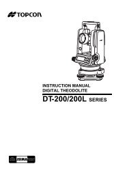
Nomenclature and Functions<br />
<strong>RL</strong>-<strong>VH4G</strong><br />
Rotary head<br />
Laser emitting window<br />
Beam aperture<br />
Head protector<br />
Magnetic Scanning Target<br />
Lock button<br />
Handle<br />
Control panel<br />
Index<br />
Magnet<br />
Datum line<br />
Index<br />
Reflectors<br />
Leveling screw<br />
Lines may appear on the reflector strips.<br />
They are part of normal manufacturing<br />
process and do not effect performance.<br />
Battery holder<br />
Battery compartment lock<br />
9
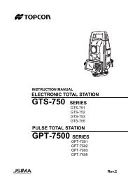
Control Panel<br />
X/Y axis selection key Manual mode lamp<br />
Select X or Y axis for ON: Manual leveling mode<br />
manual beam sloping. OFF: Auto-leveling mode<br />
10<br />
Low battery alert<br />
Alignment<br />
control<br />
X/Y axis lamp<br />
Level<br />
For vertical<br />
operation<br />
Auto/manual leveling control<br />
ON/OFF of Auto-leveling. To turn off<br />
the auto-leveling, press this key twice.<br />
To turn on the auto-leveling again,<br />
Leveling lamp<br />
Flashing: Laser is leveling<br />
On: Auto-leveling is completed<br />
(<strong>RL</strong>-<strong>VH4G</strong> remote control model has<br />
standby mode)<br />
Speed control<br />
With 'Laser Pointing<br />
Mode'<br />
selected, the rotation<br />
speed of the<br />
head can be<br />
changed.<br />
Power switch<br />
Mode switch control<br />
Laser mode is switched<br />
alternately as follows.<br />
Scan mode<br />
Head rotates slowly,<br />
searching for Magnetic<br />
Scanning Target. When<br />
target is placed in beam<br />
path, laser rapidly scans<br />
back and forth on target.<br />
press this key once.<br />
The laser output is not stable for several minutes when the power is on or the mode of laser is changed.<br />
After the beam is stabilized (display does not show WAIT), the mode can be changed.<br />
Laser sensor mode<br />
Laser sensor mode<br />
Head rotates at 300 rpm.<br />
Use this setting when using<br />
an optional electronic laser<br />
sensor such as the <strong>Topcon</strong><br />
LS-70.<br />
Laser pointing mode<br />
Head stops rotating and the<br />
beam can be positioned by<br />
manually turning the head.
Preparation for Use<br />
Battery Installation<br />
For battery placement or replacement instructions, see Maintaining Power Sources section,<br />
page 27.<br />
Instrument Set-up Procedure<br />
Horizontal Rotation<br />
1 Set the instrument on any smooth surface that is<br />
within ±5° of true level. The <strong>RL</strong>-<strong>VH4G</strong> auto-level<br />
system will not function if the unit is placed more<br />
that 5° out of level. For best operation, it is recommended<br />
that it be mounted to a tripod or the<br />
<strong>Topcon</strong> Wall Mount Model 1C .<br />
Slope can be set in both axes, X and Y. See "Setting<br />
Slope" section, page 20.<br />
Horizontal<br />
Leveling range<br />
11
Vertical Rotation<br />
1 Place the instrument on its back as shown in the illustration.<br />
2 Turn the leveling screw (s) underneath the instrument until the<br />
bubble in the level vial on the operational panel is centered.<br />
Battery Warning Lamp<br />
Flashing : The power is low<br />
ON Solid: Dead batteries<br />
Replace the batteries with new ones.<br />
Auto-leveling Lamp<br />
Flashing : Auto-leveling is in process. When automatic leveling is almost complete, the<br />
flashing rate will be slow. The head will not rotate and the laser beam will not<br />
emit during the auto-leveling process.<br />
ON Solid :Auto-leveling is complete.<br />
The rotary head is active and emits the laser beam.<br />
Turning Auto-leveling Off<br />
To turn OFF the auto-leveling function (manual mode), press the Auto/Manual control pad<br />
twice in quick succession. The manual mode indicator light will illuminate. The instrument<br />
can be positioned in any direction, the laser beam remains on and the head will rotate.<br />
IMPORTANT: In manual mode, the laser beam will not shut off if disturbed! To return to Autoleveling<br />
mode, press Auto/Manual control pad once.<br />
12
Operation<br />
Scanning Mode<br />
In scan mode, the laser rotates slowly, "searching" for the Magnetic Scanning Target. When<br />
the target is properly placed in the beam path, the laser beam will scan rapidly back and forth<br />
on the target and "track" the target as it is moved in its path.<br />
1 To change to scanning mode when operating, press the Mode Control Pad (see page 10).<br />
2 To initiate target scanning, place the Magnetic Scanning Target in the beam path with the<br />
reflective strips facing toward the laser.<br />
Vertical rotation<br />
Horizontal rotation<br />
Set scanning mode<br />
Face the target toward the instrument to start scanning.<br />
3 To end target scanning and resume searching beam, remove target from beam path.<br />
13
Continuous scan<br />
(Scan line length can be "Drawn" and held for "Hands-free" operation)<br />
Place target in beam path and hold for a moment. The scanning beam will hesitate, then<br />
start again.<br />
When the target is now removed the beam will continue to scan automatically.<br />
To change the length of the scanning line, move the target left or right after the initial scan<br />
hesitation and the scanning line length will increase until the target is removed.<br />
Scanning hesitates<br />
and starts again.<br />
Move the target left or right while<br />
scanning, the scanning line will<br />
lengthen. The "drawn" line will<br />
continue to scan without target<br />
for hands-free scan operation.<br />
To cancel the "Drawn" scan simply:<br />
Place the target into the scanning laser beam path again for more than two seconds.<br />
14
Laser Sensor Mode<br />
For long range or outdoor applications, the instrument can be used with an optional electronic<br />
laser sensor. The <strong>Topcon</strong> LS-70G model is recommended. Press the Mode Control<br />
Pad to select Laser sensor mode. The beam rotates at 300 rpm in this setting.<br />
• This mode can also be set with the Remote Controller RC-30.<br />
• Level sensors other than the LS-70G cannot be used.<br />
Laser Pointing Mode (stop)<br />
This mode stops rotation and allows the laser beam to be pointed<br />
by manually rotating the head. Press the mode control pad to select<br />
Laser pointing mode. Beam rotation stops in this mode.<br />
Laser pointing<br />
• The laser beam cannot be moved with the Remote<br />
Controller RC-30.<br />
Changing rotation speed<br />
(only available in Laser pointing mode)<br />
After selecting Laser pointing mode, press either Speed Control<br />
pad to change rotation speed. The right pad increases the rotation<br />
speed. The left pad reduces the rotation speed.<br />
• This mode can be used with the Remote Controller RC-30.<br />
15
How to Remove/Install Head Protector<br />
When the head protector post blocks the laser beam and interferes with operation,<br />
remove the head protector from the instrument.<br />
How to Remove<br />
1 Press the lock button to release the lock.<br />
Post<br />
Lock but-<br />
2 Set the angle of the head protector to approximately 45°.<br />
16
3 Pull the head protector in the direction of the arrow.<br />
Note<br />
• When the head protector is installed, do not hold by upper section of the head<br />
protector when transporting. Doing so may cause head protector to come off,<br />
with instrument falling off and may be damaged.<br />
17
How to Install<br />
1 Insert the head protector pin into the groove of the instrument until you feel it click.<br />
Pin, Groove<br />
2 Bring down the head protector until you hear a clicking sound.<br />
3 Check that the head protector is securely locked.<br />
18
Height Alert function<br />
When auto-leveling and height alert function are active, this function prevents the instrument<br />
from operating if it is disturbed (after the laser beam emits for one minute). This<br />
helps insures accurate control. If the height or inclination of the instrument changes, the<br />
height of instrument should be verified and re-established if necessary.<br />
1 To activate the Height Alert function, depress and<br />
hold the left Alignment control pad (see page 10) on<br />
the control panel while turning on the instrument by<br />
pressing the Power control pad. The three LEDs<br />
(Leveling, Manual, Battery) will flash at the same time<br />
for three seconds.<br />
Battery LED<br />
Leveling LED<br />
Manual LED<br />
2 When this function is active and the unit is disturbed,<br />
three visible LEDs will rapidly flash.<br />
3 To re-activate auto-leveling and check the beam height, turn the unit off, then on again by<br />
pressing the Power control pad twice. After auto-leveling is complete, check the beam<br />
height to confirm it has not changed.<br />
4 The Height Alert function is now inactive. To re-activate, turn unit off and repeat step 1.<br />
19
Setting Slopes<br />
The laser beam can be manually sloped in either the X or Y axis (single slope) or both axes<br />
(compound slope).<br />
With the inclination of the instrument as the standard, laser beam can be sloped within<br />
the range of ±5° up or down.<br />
• The standard for the inclination is the inclination of the instrument, not that of the<br />
rotating head immediately after the auto-leveling.<br />
• This mode can be used with the Remote Controller RC-30.<br />
X axis<br />
Y axis<br />
Inclination of the<br />
instrument<br />
Horizontal<br />
Compound slope<br />
Single Axis<br />
Dual Axes<br />
20
How to set slopes<br />
1 Turn the instrument on by pressing the Power control pad. Auto-leveling will start.<br />
2 Press the X/Y Axis Selection control pad once (see page 10). The X axis lamp will flash.<br />
To change to Y axis, press the X/Y pad once again. Pressing the X/Y pad toggles<br />
between X and Y axis selection.<br />
3 Select the axis for which you would like to set the slope.<br />
4 Select Laser pointing mode to stop beam rotation and manually<br />
align the beam over the direction of the selected axis<br />
(see illustration on previous page.)<br />
5 To move the laser beam up or down, press and hold the right<br />
or left Alignment Control pad. The Manual mode lamp will<br />
illuminate. The flashing lamp for the selected axis will<br />
change to solid after several seconds indicating that the<br />
slope has been entered in the direction of the selected axis.<br />
6 After setting the slope for one axis, press the X/Y axis selection<br />
key to select the second axis. Repeat procedures 4 and<br />
5 to set the slope for the second axis.<br />
Cancelling slope settings<br />
Press the Manual Mode pad. The instrument returns to autoleveling<br />
mode.<br />
Sample; Laser pointing mode<br />
Move the beam up or down by<br />
pressing the right or left alignment<br />
keys<br />
21
Line Control (manual vertical beam alignment)<br />
1 Position the instrument for vertical operation as<br />
instructed on page 12.<br />
2 Press the Power Control pad to turn unit on.<br />
When auto-leveling is complete, the laser beam<br />
will be emitted.<br />
3 Select the Laser Pointing operating mode and<br />
manually rotate the rotating head to align the triangular<br />
mark t with the center of the mountain<br />
mark on the rotating head.<br />
4 Move the instrument to align Point A with the<br />
center of the laser.<br />
5 Rotate the head so the beam is pointing toward<br />
point B. Press either one of the Alignment Control<br />
pads to move the beam right or left until it is<br />
precisely aligned to point B.<br />
22
6 Select the operating mode using the Mode Control pad best suited for your application.<br />
• This mode can be used with the Remote Controller RC-30.<br />
• While an alignment control pad is pressed the auto-leveling beam shut-off will not<br />
operate.<br />
23
RC-30 Remote Control<br />
RC-30 Remote Control (for remote compatible units only, see page 10)<br />
Transmission lamp<br />
Battery warning lamp<br />
for RC-30<br />
Stop beam control<br />
(Not operable)<br />
Laser Power Switch (Standby mode)<br />
Pressing this switch for more than three seconds<br />
puts laser in standby mode,<br />
allowing the user to conserve battery power.<br />
If laser remains in standby mode for 2 hours, laser<br />
will turn off automatically.<br />
Mode switch control<br />
Speed control<br />
Alignment control<br />
X/Y axis lamp<br />
Manual focus control<br />
(Not operable)<br />
Slope mode /<br />
X/Y axis selection<br />
Press this key for more than three seconds to set<br />
slope mode or select X or Y axis.<br />
24
Description of RC-30 functions<br />
Laser power switch<br />
(Standby mode)<br />
Transmission lamp<br />
Battery warning<br />
lamp for RC-30<br />
Speed control<br />
Alignment control<br />
X/Y axis lamp<br />
Mode switch<br />
control<br />
X/Y axis selection<br />
Stop beam control<br />
Manual focus<br />
control<br />
Pressing for more than three seconds turns laser standby mode on or off.<br />
Laser turns off if standby mode continues for two hours.<br />
(This mode cannot be used when the main power of the rotating laser is OFF.)<br />
This lamp will indicates a signal is being transmitted by the RC-30.<br />
It should illuminate any time a control pad is pressed.<br />
Battery warning for RC-30.<br />
Replace the batteries with new ones.<br />
The rotation speed of the rotary head can be changed.<br />
Moves beam up or down (horizontal rotation).<br />
Moves beam right or left (vertical rotation).<br />
(Valid when axis is selected with the X/Y axis selection key.)<br />
Indicates axis selected during beam sloping operation.<br />
Laser mode is switched alternately as follows.<br />
Scan mode / Laser sensor mode / Laser pointing mode.<br />
Sets slope mode by pressing for more than three seconds.<br />
Lightly pressing this key for short time will switchover the X and Y axis.<br />
Select X or Y axis for manual grading.<br />
To cancel the slope mode press this key for more than three seconds.<br />
(Press the alignment key when in the slope mode, only then will the rotating laser<br />
switch to the slope mode.)<br />
(Not operable)<br />
(Not operable)<br />
25
U<br />
T<br />
S<br />
R<br />
OX<br />
P<br />
V<br />
W<br />
U<br />
X<br />
T<br />
O<br />
S<br />
P<br />
Q<br />
R<br />
How to set remote control communication channel<br />
The same channel must be set on the <strong>RL</strong>-<strong>VH4G</strong> and the RC-30 remote controller.<br />
<strong>RL</strong>-<strong>VH4G</strong><br />
1 Remove the battery cover by turning the<br />
battery compartment lock to “OPEN”.<br />
2 Turn the channel switch to set a channel<br />
by using a small straight screwdriver<br />
(see illustration for switch location).<br />
3 Replace the battery cover and turn the<br />
knob to “Lock”.<br />
Channel<br />
switch<br />
X Y<br />
VW<br />
Q<br />
<strong>RL</strong>-<strong>VH4G</strong><br />
RC-30<br />
1 Remove the rubber cover from the channel<br />
switch on the back of the RC-30.<br />
2 Turn the channel switch to the same<br />
channel position set on the <strong>RL</strong>-<strong>VH4G</strong>.<br />
3 Replace the rubber cover.<br />
Channel<br />
switch<br />
RC-30<br />
26
Maintaining Power Sources<br />
Replacing dry batteries<br />
1 Remove the battery cover by turning the battery compartment<br />
lock to “OPEN”.<br />
2 Remove the old batteries and replace with four (4)<br />
new “D” cell alkaline batteries making sure each is<br />
placed in the proper direction as indicated.<br />
3 Replace the battery cover and turn the knob to “Lock”.<br />
Note<br />
• Replace all 4 batteries with new ones.<br />
• Do not mix old batteries and new ones.<br />
27
X/Y<br />
X/Y<br />
Checking and Adjusting<br />
There are three areas of performance the user should check periodically.<br />
Horizontal Calibration<br />
Horizontal Rotation Cone<br />
Vertical Calibration<br />
The Horizontal Calibration and Vertical Calibration can be easily checked and, in most<br />
cases, adjustments can be made by the user. Horizontal Rotation Cone can be checked by<br />
the user, but if an error is found, adjustments must be made by a <strong>Topcon</strong> service facility.<br />
Attaching the calibration decals<br />
Before calibration, attach the calibration decals to the instrument as shown below. The calibration<br />
decal shows the calibration function of certain control pads on the control panel.<br />
Calibration Decals<br />
Y<br />
V<br />
X<br />
2 X<br />
3<br />
Y<br />
V<br />
1 START<br />
4 ENTER<br />
ERROR<br />
CALIBRATION<br />
1 START-While pressing ,press<br />
2 XCAL-ON,YCAL-press ON<br />
VCAL-ON<br />
3 LASER BEAM CORRECTION<br />
- or<br />
4 ENTER-press<br />
28
Horizontal Calibration<br />
(1)Checking Calibration<br />
30m (98feet)<br />
Instrument as seen from above<br />
Target<br />
Wall<br />
Panel side<br />
1 Set up a tripod 30m(98ft) from a wall. Mount the instrument<br />
on the tripod, facing the X1 side toward the wall.<br />
2 Turn the unit on and allow auto-leveling to complete.<br />
3 Place a piece of paper on the wall. Detect the laser position<br />
on the wall with target and mark it. Turn the instrument<br />
off.<br />
4 Loosen the tripod screw, rotate the instrument 180<br />
degrees.<br />
Note • When rotating the instrument, make sure the heights of the instruments are aligned.<br />
• When the laser beam is difficult to see, it can be checked in the Laser sensor<br />
mode or the Laser pointing mode.<br />
29
5 Turn the unit on again and allow auto-leveling to<br />
complete.<br />
6 Make a new mark (Mb) where the laser beam<br />
strikes the paper.<br />
7 Measure the distance between the first mark (Ma)<br />
and the second mark (Mb). No calibration is necessary<br />
if distance is within 6mm (1/4 of an inch).<br />
8 Repeat procedure for the Y axis.<br />
If less than 6mm(.23 inches)<br />
No calibration Necessary<br />
X1 laser beam<br />
X2 laser beam<br />
30m (98feet)<br />
30
(2) Adjusting Calibration<br />
If the distance between either set of marks is more than 6mm (1/4 of an inch) but less than<br />
25mm (1 inch), turn the unit off by pressing the [START] pad once and use the following<br />
procedure to calibrate the laser. Confirm that unit has shut off before beginning the procedure.<br />
(In steps 2 and 3, use of optional RC-30 remote control can be helpful. See page 33.)<br />
1 While pressing the [ENTER] key, press the [START] key. This activates the X axis calibration<br />
mode. Confirm that the [X] LED is lit.<br />
3<br />
1<br />
START<br />
Center<br />
position<br />
Laser beam<br />
up or down<br />
2<br />
X<br />
X/Y<br />
Y<br />
V<br />
4 ENTER<br />
ERROR<br />
2 By pressing the right or left Alignment Control pad, move the X2 (Mb) laser beam up or<br />
down until its centered between marks Ma and Mb.<br />
• This operation can be performed with the Remote Controller RC-30.<br />
Note • When using the RC-30, select the X axis with the X/Y axis selection key and<br />
move the laser beam up or down with the alignment key.<br />
31
3 When the beam is precisely centered, press the [ENTER] key. The [X] LED will flash.<br />
The [X] LED will flash.<br />
When the flashing stops, the X axis calibration adjustment is made and power is turned<br />
off.<br />
4 For Y axis calibration, turn the unit as instructed in step 1 then press the X/Y Axis Selection<br />
pad.<br />
Confirm that the [Y] LED is lit, then repeat steps 2 to 4 for the Y axis.<br />
Repeat the checking procedure to confirm proper calibration has been made.<br />
• If the calibration is greater than the adjustment allows, the error LED will start<br />
Note flashing. (See “Error Code” on P46)<br />
If this occurs, contact your <strong>Topcon</strong> dealer.<br />
32<br />
• This operation can be performed with the Remote Controller RC-30.<br />
When using the RC-30, press the [ENTER] key on the RC-30 unit.<br />
(The [ENTER] key for the RC-30: The same mark as the [ENTER] key for the instrument.)<br />
• This operation can be performed with the Remote Controller RC-30.<br />
When using the RC-30, select the Y axis using the X/Y axis selection key and<br />
move the laser beam up and down with the Alignment control key.<br />
• When the laser beam is difficult to see, it can be adjusted in the Laser sensor<br />
mode or the Laser pointing mode.
Horizontal Rotation Cone Error<br />
Perform the following check after completing "Horizontal Calibration" on the previous page.<br />
Minimum about 30m/98ft<br />
Cone error<br />
Wall<br />
A<br />
Datum position Wall<br />
B<br />
Wall<br />
A<br />
Wall<br />
B<br />
1 Set up the laser centered between two walls approximately 30m (98 ft) apart. Orient the<br />
instrument so one axis, either X or Y, is facing the walls.<br />
2 Locate and mark the position of the rotating laser beam on both walls using the target.<br />
3 Turn off the instrument and move the instrument closer to wall A (1m to 2m /3 ft to 6 ft).<br />
Do not change the axis orientation of the instrument. Turn the instrument on.<br />
4 Again locate and mark the position of the rotating laser beam on both walls.<br />
5 Measure the distance between the first and second marks on each wall.<br />
6 If the difference between each set of marks is less than 3mm (1/8 of an inch), no error<br />
exists.<br />
Note • If the error is grater than 3mm (1/8 of an inch), contact your <strong>Topcon</strong> dealer.<br />
33
Vertical Calibration<br />
Perform the following check after completing "Horizontal Calibration" on the previous page.<br />
(1)Checking<br />
1 Set up the instrument half way between<br />
two walls a minimum of 30m (98 ft) apart.<br />
(The instrument can be facing either<br />
direction X or Y. No tripod is used.)<br />
2 Turn the power switch on.<br />
3 Place a piece of paper on each wall (A<br />
and B).<br />
34<br />
Mark the horizontal laser positions (Ma and Mb) on each wall using target.<br />
about 30 m (98ft)<br />
4 Turn the power switch off. Position the<br />
instrument for vertical operation (see<br />
instruction on page 12) with the rotary<br />
head directly facing wall A (see illustration).<br />
Make sure the unit is level by<br />
checking the level vial. Use the leveling<br />
screw to adjust if necessary.<br />
5 Turn the power switch on. (Laser beam<br />
should be in scanning mode.)<br />
6 Mark where the split beam emitted from<br />
the top of the rotary head strikes wall A<br />
(Ha). Measure the distance (dHa)<br />
between marks Ma and Ha.<br />
Wall<br />
A<br />
Wall<br />
A<br />
about 1m<br />
about 15 m<br />
(49ft)<br />
about 15 m<br />
(49ft)<br />
Foot<br />
Wall<br />
B<br />
Wall<br />
B
7 Without moving the position of the front foot, pivot the instrument so the rotary head is<br />
now facing wall B.<br />
8 Mark where the split beam emitted from<br />
the top of the rotary head strikes wall B<br />
(Hb). Measure the distance (dHb)<br />
between marks Mb and Hb.<br />
9 Compare the two measurements dHa and<br />
dHb. If the difference between the two<br />
measurements is less than 3mm (1/8 of<br />
an inch), no adjustment is necessary. Otherwise,<br />
adjust as follows.<br />
about 1m<br />
about 30 m (98ft)<br />
35
(2)Adjusting Calibration<br />
Turn the unit off by pressing the [START] pad once. Confirm that unit has shut off before<br />
beginning the following procedure.(In step 2 and 3, optional RC-30 remote control is helpful.)<br />
1 Without moving the unit, press the [ENTER] and [START] keys simultaneously.<br />
2 Press either the right or left key on the Alignment Control pad to move the laser beam up<br />
or down on wall B until the measurement for the distance dHb is the same as the measurement<br />
dHa on wall A.<br />
• This operation can be performed with the Remote Controller RC-30.<br />
When using the RC-30, select the Y axis using the X/Y axis selection key and<br />
move the laser beam up and down with the Alignment control key.<br />
3<br />
1<br />
START<br />
Laser beam<br />
up or down<br />
2<br />
X<br />
X/Y<br />
Y<br />
V<br />
4 ENTER<br />
ERROR<br />
36
3 When the beam is positioned so the two measurements are the same, press the [ENTER]<br />
key. The [V] LED will flash.<br />
When the flashing stops, the vertical calibration adjustment is made and power is turned<br />
off.<br />
Note<br />
• This operation can be performed with the remote controller RC-30.<br />
When using the RC-30, press the [ENTER] key on the RC-30 unit.<br />
(The [ENTER] key for the RC-30: The same mark as the [ENTER] key for the<br />
instrument.)<br />
• If the calibration is greater than the adjustment allows, the error LED will<br />
start flashing. If this occurs, contact your <strong>Topcon</strong> dealer.<br />
Repeat the checking procedure to confirm proper calibration has been made.<br />
37
Standard / Optional Accessories<br />
LS-70G Laser Sensor<br />
Beam receiving window<br />
Display<br />
The indicators are located on front and back<br />
sides of the instrument.<br />
On-grade Index<br />
On-grade precision switch<br />
Two on-grade precision options are available,<br />
normal precision and high precision. By pressing<br />
this switch, the precision options are<br />
switched alternately. Active precision setting<br />
is shown on the display.<br />
(Normal precision is the default setting when<br />
power is turned on.)<br />
Audio indicator switch<br />
(Quite/Loud/OFF)<br />
On-grade Index<br />
Power switch<br />
Audio speaker<br />
Auto-cut off function(LS-70G)<br />
The power will be turned off automatically if no laser beam is detected within<br />
approximately 30 minutes. (To turn the sensor on again, press the power switch.)<br />
The rotating laser safety lock system display and rotating laser battery level display<br />
are not available with the LS-70G.<br />
Level sensors other than the LS-70G cannot be used.<br />
38
Laser sensor holder model 6<br />
Wall Mount 1C<br />
154<br />
153<br />
152<br />
151<br />
150<br />
149<br />
148<br />
Clamp knob<br />
Laser Mounting<br />
screw<br />
Clamp lever<br />
147<br />
146<br />
HOLDER-6<br />
139 131<br />
138<br />
137<br />
136<br />
135<br />
134<br />
133<br />
132<br />
131<br />
Laser sensor<br />
holder model 6<br />
Elevation<br />
clamp knob<br />
Laser sensor<br />
39
Battery holder DB-49C<br />
Rechargeable battery pack BT-63Q<br />
AC/DC converter<br />
For Charging<br />
1 Plug the AC/DC converter into the DB-49C battery<br />
holder.<br />
2 Insert the converter power cord in an outlet.<br />
3 Complete charging by unplugging the converter<br />
connector from the DB-49C battery<br />
holder after approximately 9 hours.<br />
4 Unplug the converter power cord from the outlet.<br />
The LED of DB-49C will indicate charging status;<br />
DB-49C<br />
BT-63Q<br />
DB-49C<br />
Red ON : Charging.<br />
Green ON : Charging completed.<br />
Green flashing : DB-49C is not connected to BT-63Q.<br />
Red flashing : BT-63Q protection feature is working automatically.<br />
<strong>RL</strong>-<strong>VH4G</strong> can be used in this state.<br />
Automatic protection feature; In case of overcharge or high or low temperature state exceeding<br />
charging range, charging will be stopped or changed to protect battery.<br />
• DB-49C can be used with dry batteries instead of BT-63Q.<br />
AC/DC converter<br />
40
Storage Precautions<br />
Always clean the instrument after use.<br />
Use a clean cloth, moistened with a neutral detergent or water. Never use an abrasive<br />
cleaner, ether, thinner benzene, or other solvents.<br />
Always make sure instrument is completely dry before storing. Dry any moisture with a soft,<br />
clean cloth.<br />
41
How to Store<br />
How to Store (1)<br />
LS-70G<br />
Laser sensor<br />
holder model 6<br />
Wall Mount 1C<br />
42
How to Store (2)<br />
AC/DC convertor<br />
BT-63Q<br />
43
Specifications<br />
<strong>RL</strong>-<strong>VH4G</strong><br />
Accuracy<br />
Horizontal : ±20"<br />
Vertical : ±20"<br />
Auto-leveling range : ±5°<br />
Measuring range (Diameter) : 60m(197ft)<br />
Using with LS-70G : 2m(6.5ft)~300m(984ft)<br />
Rotation speeds : Changeable (0 ~ 300rpm)<br />
Scanning width Maximum 180°<br />
Light source : Solid-state laser (Visible laser)<br />
Power supply : 4D-CELL Alkaline dry batteries<br />
Continuous operating time : Approx. 27 hours<br />
at +20°C (+68°F)<br />
Approx. 247 hours (When using the rechargeable internal<br />
power source BT-63Q)<br />
Tripod screw : Flat and dome head type, W 5”/8 × 11threads<br />
Operating temperature : -20°C to +50°C (-4°F to +122°F)<br />
Protection against<br />
: IP54 (Category 2)<br />
water and dust<br />
Dimensions : 182(L) × 167(W) × 240(H) mm [7.2(L) × 6.6(W) × 9.4(H) in]<br />
Weight : 2.6 kg [5.7 lbs] (without dry batteries)<br />
44
Remote controller RC-30<br />
Operating range (Radius)<br />
Power supply<br />
Operating time<br />
Protection against<br />
Dimensions<br />
Weight<br />
:<br />
:<br />
:<br />
:<br />
:<br />
:<br />
Approx. 80m (262ft)<br />
Approx. 40m (131ft) [for export to Taiwan]<br />
(Operating range will vary depending on environmental<br />
conditions.)<br />
Three "AA" alkaline batteries, DC4.5V<br />
Approx. 3 months (depends on the nature of use)<br />
IPX6Å@ (Based on the standard IEC 60529)<br />
157(L)×64(W)×34(H) mm<br />
[6.2(L)×2.5(W)×1.3(H) in]<br />
160 g[0.35 lbs] (without dry batteries)<br />
45
Error Code<br />
Use the table below to determine operation<br />
errors indicated by blinking lamps on<br />
the control panel.<br />
If corrective action listed does not correct<br />
error, please contact your local <strong>Topcon</strong><br />
dealer.<br />
D<br />
C<br />
E<br />
A<br />
B<br />
Lamp Indication Error Code Corrective Action<br />
Lamp A, B and C blink in turn Auto-leveling range error Correct tilt of the instrument until it less than 5 degrees.<br />
Lamp C lights Battery power out error Replace all 4 batteries with new ones at the same<br />
time.<br />
Lamp A, B and C blink simultaneously<br />
Height alert error<br />
Turn power off, rough level the instrument, then turn<br />
power on again. Check height of laser beam as it<br />
may have changed.<br />
Lamp B blinks Calibration error Repeat calibration procedure. If error repeats contact<br />
your local <strong>Topcon</strong> dealer.<br />
Lamp D and E blink simultaneously<br />
Internal error<br />
Turn power off, then on again. If error repeats contact<br />
your local <strong>Topcon</strong> dealer.
©2007 TOPCON CORPORATION<br />
ALL RIGHTS RESERVED
TOPCON POSITIONING SYSTEMS, INC.<br />
7400 National Drive, Livermore, CA 94551, U.S.A.<br />
Phone: 925-245-8300 Fax: 925-245-8599 www.topcon.com<br />
TOPCON CALIFORNIA<br />
3380 Industrial Blvd, Suite 105, West Sacramento, CA 95691, U.S.A.<br />
Phone: 916-374-8575 Fax: 916-374-8329<br />
TOPCON EUROPE POSITIONING B.V.<br />
Essebaan 11, 2908 LJ Capelle a/d IJssel, The Netherlands.<br />
Phone: 010-458-5077 Fax: 010-284-4941 www.topconeurope.com<br />
IRELAND OFFICE<br />
Unit 69 Western Parkway Business Center<br />
Lower Ballymount Road, Dublin 12, Lreland<br />
Phone: 01460-0021 Fax: 01460-0129<br />
TOPCON DEUTSCHLAND G.m.b.H.<br />
Giesserallee 31, 47877 Willich, GERMANY<br />
Phone: 02154-885-100 Fax: 02154-885-111 info@topcon.de<br />
www.topcon.de<br />
TOPCON S.A.R.L.<br />
89, Rue de Paris, 92585 Clichy, Cedex, France.<br />
Phone: 33-1-41069490 Fax: 33-1-47390251 topcon@topcon.fr<br />
TOPCON SCANDINAVIA A. B.<br />
Neongatan 2 S-43151 Mölndal, SWEDEN<br />
Phone: 031-7109200 Fax: 031-7109249<br />
TOPCON (GREAT BRITAIN)LTD.<br />
<strong>Topcon</strong> House Kennet Side, Bone Lane, Newbury, Berkshire RG14 5PX U.K.<br />
Phone: 44-1635-551120 Fax: 44-1635-551170<br />
survey.sales@topcon.co.uk laser.sales@topcon.co.uk<br />
TOPCON SOUTH ASIA PTE. LTD.<br />
Blk 192 Pandan Loop, #07-01 Pantech Industrial Complex, Singapore 128381<br />
Phone: 62780222 Fax: 62733540 www.topcon.com.sg<br />
TOPCON INSTRUMENTS (THAILAND) CO., LTD.<br />
77/162 Sinn Sathorn Tower, 37th Fl.,<br />
Krungdhonburi Rd., Klongtonsai, Klongsarn, Bangkok 10600 Thailand.<br />
Phone: 02-440-1152~7 Fax: 02-440-1158<br />
TOPCON INSTRUMENTS (MALAYSIA) SDN. BHD.<br />
Excella Business Park Block C, Ground & 1st Floor, Jalan Ampang Putra,<br />
Taman Ampang Hilir, 55100 Kuala Lumpur, MALAYSIA<br />
Phone: 03-42701068 Fax: 03-42704508<br />
TOPCON KOREA CORPORATION<br />
2F Yooseoung Bldg., 1595-3, Seocho-Dong, Seocho-gu, Seoul, 137-876, Korea.<br />
Phone: 82-2-2055-0321 Fax: 82-2-2055-0319 www.topcon.co.kr<br />
TOPCON OPTICAL (H.K.) LIMITED<br />
2-4/F Meeco Industrial Bldg., No. 53-55 Au Pui Wan Street, Fo Tan Road,<br />
Shatin, N.T., Hong Kong<br />
Phone: 2690-1328 Fax: 2690-2221 www.topcon.com.hk<br />
TOPCON CORPORATION BEIJING OFFICE<br />
Building A No.9, Kangding Street<br />
Beijing Economic Technological Development Area, Beijing, China 100176<br />
Phone: 10-6780-2799 Fax: 10-6780-2790<br />
TOPCON CORPORATION BEIRUT OFFICE<br />
P. O. BOX 70-1002 Antelias, BEIRUT-LEBANON.<br />
Phone: 961-4-523525/961-4-523526 Fax: 961-4-521119<br />
TOPCON CORPORATION DUBAI OFFICE<br />
C/O Atlas Medical FZCO., P. O. Box 54304, C-25, Dubai Airport Free Zone,UAE<br />
Phone: 971-4-2995900 Fax: 971-4-2995901<br />
TOPCON CORPORATION<br />
75-1 Hasunuma-cho, Itabashi-ku, Tokyo 174-8580, Japan<br />
Phone: 3-3558-2520 Fax: 3-3960-4214 www.topcon.co.jp<br />
3C