- Page 1 and 2: PART NO. 03116SL (Rev. F) Service M
- Page 3 and 4: Table Of Contents Chapter 1 − Saf
- Page 5 and 6: Chapter 1 Safety Safety Table of Co
- Page 7 and 8: Maintenance and Service 1. Before s
- Page 9 and 10: Safety and Instruction Decals Numer
- Page 11 and 12: Chapter 2 Table of Contents Product
- Page 13 and 14: Torque Specifications Recommended f
- Page 15 and 16: Standard Torque for Dry, Zinc Plate
- Page 17 and 18: Maintenance Maintenance procedures
- Page 19 and 20: Table of Contents GENERAL INFORMATI
- Page 21 and 22: Specifications Item Make / Designat
- Page 23 and 24: Kubota Diesel Engine This page is i
- Page 25 and 26: Removal 1. Remove air cleaner compo
- Page 27 and 28: Removal CAUTION 3 The muffler and e
- Page 29 and 30: DANGER Because diesel fuel is highl
- Page 31 and 32: Removal 1. Park machine on a level
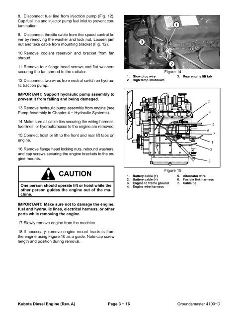
- Page 33: Engine Removal 1. Park machine on a
- Page 37 and 38: Disassembly 1. If engine is in mach
- Page 39 and 40: Chapter 4 Hydraulic System Table of
- Page 41 and 42: General Information Hydraulic Hoses
- Page 43 and 44: Towing Traction Unit IMPORTANT: If
- Page 45 and 46: Hydraulic Schematic Groundsmaster 4
- Page 47 and 48: Traction Circuit The traction circu
- Page 49 and 50: Lower Cutting Deck A three section
- Page 51 and 52: Raise Cutting Deck A three section
- Page 53 and 54: Mow Circuit Hydraulic flow for the
- Page 55 and 56: Steering Circuit A three section ge
- Page 57 and 58: Hydraulic Test Fitting Kit - TOR407
- Page 59 and 60: Problem Four wheel drive will not e
- Page 61 and 62: Testing The most effective method f
- Page 63 and 64: Procedure for Traction Circuit Char
- Page 65 and 66: Procedure for Traction Circuit Reli
- Page 67 and 68: Procedure for Cutting Deck Circuit
- Page 69 and 70: Procedure for Cutting Deck Gear Pum
- Page 71 and 72: Procedure for Cutting Deck Manifold
- Page 73 and 74: Procedure for Cutting Deck Motor Ca
- Page 75 and 76: Procedure for Steering Circuit Reli
- Page 77 and 78: Procedure for Lift/Lower Circuit Re
- Page 79 and 80: Procedure for Steering and Lift/Low
- Page 81 and 82: Procedure for Counterbalance Pressu
- Page 83 and 84: Procedure for Rear Traction Circuit
- Page 85 and 86:
Procedure for Traction Circuit Redu
- Page 87 and 88:
Service and Repairs General Precaut
- Page 89 and 90:
Charge Hydraulic System NOTE: When
- Page 91 and 92:
Removal (Fig 43) 1. Park machine on
- Page 93 and 94:
3. Remove pump from vise, hold pump
- Page 95 and 96:
Hydraulic System This page is inten
- Page 97 and 98:
Removal (Fig. 45) 1. Park machine o
- Page 99 and 100:
Disassembly (Fig. 46) 1. Position t
- Page 101 and 102:
8. Place exterior retaining ring (3
- Page 103 and 104:
6. Install wiper seal on input shaf
- Page 105 and 106:
Removal NOTE: The ports on the mani
- Page 107 and 108:
IMPORTANT: Use care when handling t
- Page 109 and 110:
Removal NOTE: The ports on the mani
- Page 111 and 112:
Hydraulic System This page is inten
- Page 113 and 114:
Hydraulic Control Manifold Service:
- Page 115 and 116:
Hydraulic Control Manifold Service:
- Page 117 and 118:
Removal 1. Park machine on a level
- Page 119 and 120:
Removal 1. Park machine on a level
- Page 121 and 122:
4. Remove motor from vise and remov
- Page 123 and 124:
Cutting Deck Motor Removal 1. Park
- Page 125 and 126:
IMPORTANT: Mark the relative positi
- Page 127 and 128:
Hydraulic System This page is inten
- Page 129 and 130:
Removal 1. Park machine on a level
- Page 131 and 132:
Disassembly (Fig. 74) 1. Plug all p
- Page 133 and 134:
Removal 1. Park machine on a level
- Page 135 and 136:
CAUTION The centering springs are u
- Page 137 and 138:
Removal (Fig. 78) 1. Park machine o
- Page 139 and 140:
Disassembly (Fig. 79) 1. Remove oil
- Page 141 and 142:
Removal (Fig. 80) 1. Park machine o
- Page 143 and 144:
Disassembly (Fig. 81) 1. Remove oil
- Page 145 and 146:
Removal (Fig. 83) 1. Park machine o
- Page 147 and 148:
Disassembly (Fig. 84) 1. Remove oil
- Page 149 and 150:
Removal 1. Park machine on a level
- Page 151 and 152:
Chapter 5 Electrical System Table o
- Page 153 and 154:
Special Tools Order special tools f
- Page 155 and 156:
Problem Engine cranks, but does not
- Page 157 and 158:
Electrical System Quick Checks Batt
- Page 159 and 160:
Cutting Deck Raise and Lower Switch
- Page 161 and 162:
Fuses The fuse blocks are located u
- Page 163 and 164:
PTO Switch The PTO switch is attach
- Page 165 and 166:
Seat Switch The seat switch is norm
- Page 167 and 168:
Start, Engine Shutdown, Seat, PTO,
- Page 169 and 170:
Engine Run Solenoid The engine run
- Page 171 and 172:
Fuel Gauge The fuel gauge can be te
- Page 173 and 174:
Glow Controller The glow controller
- Page 175 and 176:
High Temperature Shutdown Switch Th
- Page 177 and 178:
Traction Neutral Switch The tractio
- Page 179 and 180:
Wing Deck Position Switches The win
- Page 181 and 182:
Service and Repairs NOTE: For more
- Page 183 and 184:
Battery Service The battery is the
- Page 185 and 186:
Charging To minimize possible damag
- Page 187 and 188:
Chapter 6 Axles, Planetaries, and B
- Page 189 and 190:
Adjustments See Operator’s Manual
- Page 191 and 192:
CAUTION When changing attachments,
- Page 193 and 194:
This page is intentionally blank. A
- Page 195 and 196:
Planetary Wheel Drive Removal (Fig.
- Page 197 and 198:
Planetary Wheel Drive Disassembly (
- Page 199 and 200:
8. Remove cap screw and flange nut
- Page 201 and 202:
Bevel Gear Case and Axle Case The f
- Page 203 and 204:
Installation 1. Coat new shaft seal
- Page 205 and 206:
9. Remove the bevel gear case/axle
- Page 207 and 208:
Axle Shafts The following procedure
- Page 209 and 210:
6. Set the bearing preload by secur
- Page 211 and 212:
Inspection 1. Measure the different
- Page 213 and 214:
Pinion Gear to Ring Gear Engagement
- Page 215 and 216:
Chapter 7 Chassis Table of Contents
- Page 217 and 218:
Disassembly 1. Park machine on a le
- Page 219 and 220:
CAUTION When raising machine, use c
- Page 221 and 222:
Removal 1. Park machine on a level
- Page 223 and 224:
Chapter 8 Cutting Deck Table of Con
- Page 225 and 226:
Troubleshooting There are a number
- Page 227 and 228:
This page is intentionally blank. C
- Page 229 and 230:
Removal (Fig. 1) 1. Position machin
- Page 231 and 232:
This page is intentionally blank. C
- Page 233 and 234:
6. Support wing deck to prevent it
- Page 235 and 236:
Wing Deck Latch Disassembly (Fig. 1
- Page 237 and 238:
Installation (Fig. 12) 1. Position
- Page 239 and 240:
3. Using an arbor press, push the b
- Page 241 and 242:
Deck Rollers and Skids 10 9 7 6 5 8
- Page 243 and 244:
Chapter 9 Electrical Diagrams Table
- Page 245 and 246:
Groundsmaster 4100−D Electrical S
- Page 247 and 248:
Groundsmaster 4100−D Crank Circui
- Page 249 and 250:
NOTE: The drawing on this page show
- Page 251 and 252:
Groundsmaster 4100−D Main Wire Ha
- Page 253 and 254:
(D4) (D2) (D6) Groundsmaster 4100
- Page 255 and 256:
(D8) (D7) (D5) Groundsmaster 4100
- Page 257:
Groundsmaster 4100−D Cutting Deck