

caution - Toro
caution - Toro
caution - Toro

Create successful ePaper yourself
Turn your PDF publications into a flip-book with our unique Google optimized e-Paper software.
Procedure for Cutting Deck Gear Pump Flow Test<br />
NOTE: Over a period of time, the gears and wear plates<br />
in the gear pump can wear. A worn pump will by--pass<br />
oil and make the pump less efficient. Eventually, enough<br />
oil loss will occur to cause the cutting deck motors to stall<br />
under heavy cutting conditions. Continued operation<br />
with a worn, inefficient pump can generate excessive<br />
heat and cause damage to the seals and other components<br />
in the hydraulic system.<br />
1. Make sure hydraulic oil is at normal operating temperature<br />
by operating the machine for approximately 10<br />
minutes. Make sure the hydraulic tank is full.<br />
2. Park machine on a level surface with the cutting<br />
decks lowered and off. Make sure engine is off and the<br />
parking brake is engaged.<br />
CAUTION<br />
IMPORTANT: Do not fully restrict oil flow through<br />
tester. In this test, the flow tester is positioned before<br />
the relief valve. Pump damage can occur if the<br />
oil flow is fully restricted.<br />
8. Watch pressure gauge carefully while slowly closing<br />
the flow control valve until 2000 PSI is obtained. Verify<br />
with a phototac that the engine speed is 2400 RPM.<br />
9. For a normal pump, gear pump flow should be<br />
approximately 14 GPM. Shut off engine. Record test results.<br />
10.If measured flow is less than 12 GPM or if a pressure<br />
of 2000 PSI cannot be obtained, check for restriction in<br />
the pump intake line. If line is not restricted, remove gear<br />
pump and repair or replace as necessary.<br />
11.Disconnect flow tester from hydraulic hose and manifold<br />
port. Reconnect hose to the manifold.<br />
12.Repeat test for second pump section if required.<br />
Prevent personal injury and/or damage to equipment.<br />
Read all WARNINGS, CAUTIONS, and Pre<strong>caution</strong>s<br />
for Hydraulic Testing at the beginning<br />
of this section.<br />
RIGHT<br />
FRONT<br />
TO OIL COOLER<br />
Hydraulic<br />
System<br />
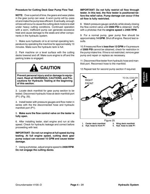
3. Locate deck manifold for gear pump section to be<br />
tested. Disconnect hydraulic hose at deck manifold port<br />
(P1) (Fig. 25).<br />
4. Install tester with pressure gauges and flow meter in<br />
series with the the disconnected hose and hydraulic<br />
manifold port (P1).<br />
1<br />
2<br />
4<br />
3<br />
5. Make sure the flow control valve on the tester is<br />
fully open.<br />
6. After installing tester, start engine and run at idle<br />
speed. Check for hydraulic leakage and correct before<br />
proceeding with test.<br />
1. Center deck manifold<br />
2. Hyd. hose to front P1<br />
Figure 25<br />
3. Wing deck manifold<br />
4. Hyd. hose to side P1<br />
IMPORTANT: Do not run engine at full speed during<br />
testing. At full engine speed, cutting deck gear<br />
pump output can exceed 15 GPM and cause tester<br />
damage.<br />
7. Using a phototac, adjust engine speed to 2400 RPM.<br />
Do not engage the cutting decks.<br />
Groundsmaster 4100--D<br />
Page 4 - 31<br />
Hydraulic System


