Electric Dropbolt Installation Instruction (Fail-Security Series)
Electric Dropbolt Installation Instruction (Fail-Security Series)
Electric Dropbolt Installation Instruction (Fail-Security Series)

Create successful ePaper yourself
Turn your PDF publications into a flip-book with our unique Google optimized e-Paper software.
Frame<br />
<strong>Electric</strong> <strong>Dropbolt</strong> <strong>Installation</strong> <strong>Instruction</strong><br />
(<strong>Fail</strong>-<strong>Security</strong> <strong>Series</strong>)<br />
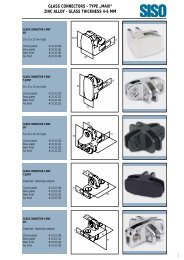
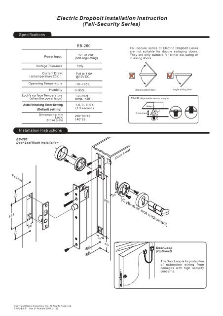
Specifications<br />
EB-260<br />
12~28 VDC<br />
(self-regulating)<br />
<strong>Fail</strong>-Secure series of <strong>Electric</strong> <strong>Dropbolt</strong> Locks<br />
are not suitable for double swinging doors.<br />
They are only suitable for either out-swing or<br />
in-swing doors.<br />
± 10%<br />
Pull in: 1.0A<br />
@12V DC<br />
-10~+45℃<br />
0~95%<br />
≦current<br />
temp. +20℃<br />
1.5,3,6,9s<br />
(1.5 second)<br />
double action door<br />
EB-260 Adjustable sensor magnet<br />
Reed<br />
single acting door<br />
260*30*48<br />
140*25<br />
5mmmaxi<br />
45<br />
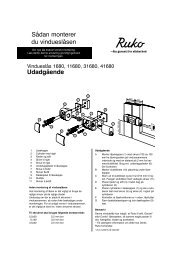
<strong>Installation</strong> <strong>Instruction</strong>s<br />
EB-260<br />
Door Leaf flush installation<br />
Door Leaf<br />
40<br />
35<br />
261<br />
(Cylinder not included)<br />
141<br />
40<br />
26<br />
31<br />
4<br />
5<br />
40<br />
Door Loop<br />
(Optional)<br />
The Door Loop is for protection<br />
of extension wiring from<br />
damages with high security<br />
concerns.<br />
Copyright Gianni Industries, Inc. All Rights Reserved.<br />
P-MU-EB-F Ver. D Publish:2007.01.25
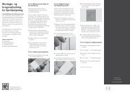
<strong>Installation</strong> <strong>Instruction</strong>s<br />
5<br />
4<br />
Door Leaf<br />
35<br />
4<br />
5<br />
Mortise cutout in door<br />
leaf for face plate .<br />
Position screws for fasten Fixing<br />
Lugs.<br />
Drill and cut as template<br />
indicated.<br />
Connect power cable to<br />
electric dropbolt.<br />
Caution:<br />
Make sure that the "+" and "-" wire are<br />
connected correctly. <strong>Fail</strong>ure to observe<br />
polarity will result in a short circuit and is not<br />
coveredbyproductswarrant.<br />
Blue<br />
Blue<br />
Black<br />
Red<br />
-<br />
+<br />
Control Device<br />
N.O. contact or Access Relay<br />
-<br />
+<br />
Power<br />
supply<br />
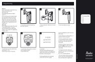
Auto Relocking Timer Setting<br />
Insert electric dropbolt into<br />
position, attach to Fixing<br />
Lugs and base.<br />
Fixing cover.<br />
Use 45X45mm tighten the<br />
cylinder<br />
1.5s 3s 6s 9s<br />
General <strong>Installation</strong> <strong>Instruction</strong>s:<br />
<br />
<br />
<br />
Ensure you have the following:<br />
*<strong>Electric</strong> <strong>Dropbolt</strong><br />
*Strike plate<br />
All rebate strips and/or frame stops be fitted before starting.<br />
Check with a suitable meter that the regulated power supply or controller being used can provide 1.2 A@12V DC (voltage<br />
tolerance ± 10%) and that the voltage can be maintained during operation under all circumstances.<br />
Warning: The connection of an incorrect voltage may result in damage not covered by the product warranty.<br />
<br />
<br />
<br />
The selection of appropriate power supply cable is very important to ensure lock receives sufficient power to operate.<br />
This product has been designed for use in weather protected areas and under normal circumstances does not require any<br />
maintenance. DO NOT OIL OR LUBRICATE.<br />
This product must be used in conjunction with a quality floor spring or door closer to ensure positive realignment on closing.<br />
Distance in feet from power source to farthest locking device<br />
Minimum<br />
Wire Gauge<br />
for12VDC<br />
Minimum<br />
Wire Gauge<br />
for24VDC<br />
Copyright Gianni Industries, Inc. All Rights Reserved.<br />
P-MU-EB-F Ver. D Publish:2007.01.25