Device for Measuring Sliding Friction on Highloft Nonwovens
Device for Measuring Sliding Friction on Highloft Nonwovens
Device for Measuring Sliding Friction on Highloft Nonwovens

Create successful ePaper yourself
Turn your PDF publications into a flip-book with our unique Google optimized e-Paper software.
are all variati<strong>on</strong>s of Da Vinci's sled method. However,<br />
when measuring the fricti<strong>on</strong> of high loft n<strong>on</strong>woven<br />
fabric batts using these methods, large scale<br />
de<str<strong>on</strong>g>for</str<strong>on</strong>g>mati<strong>on</strong> of the fabric occurs and the apparent<br />
fricti<strong>on</strong> changes with the number of batts or the<br />
thickness of the batts, even though the material, the<br />
pressure and the normal load are unchanged. This<br />
implies that the measured fricti<strong>on</strong> includes<br />
comp<strong>on</strong>ents due to the de<str<strong>on</strong>g>for</str<strong>on</strong>g>mati<strong>on</strong> of the substrate<br />
as well as the sliding fricti<strong>on</strong>. The result is an<br />
incorrect value <str<strong>on</strong>g>for</str<strong>on</strong>g> the fricti<strong>on</strong>.<br />
To address the issue of sliding and de<str<strong>on</strong>g>for</str<strong>on</strong>g>mati<strong>on</strong> in the<br />
critical area of automobile tires, special test devices<br />
have been built, including highly instrumented<br />
automobiles with professi<strong>on</strong>al drivers. The sliding<br />
fricti<strong>on</strong> and tire de<str<strong>on</strong>g>for</str<strong>on</strong>g>mati<strong>on</strong> are separated by<br />
modeling. 10 In another example, when some<strong>on</strong>e is<br />
sitting in an upholstered seat and tries to get up, they<br />
both slide across the seat and de<str<strong>on</strong>g>for</str<strong>on</strong>g>m the cushi<strong>on</strong>s.<br />
Thus the energy required to get out of the seat<br />
includes both fricti<strong>on</strong> and cushi<strong>on</strong> de<str<strong>on</strong>g>for</str<strong>on</strong>g>mati<strong>on</strong>.<br />
However, the engineering soluti<strong>on</strong> to manipulate the<br />
required energy <str<strong>on</strong>g>for</str<strong>on</strong>g> each comp<strong>on</strong>ent is different and<br />
it would be useful to clearly separate these factors so<br />
that the seat or tire could be designed rati<strong>on</strong>ally <str<strong>on</strong>g>for</str<strong>on</strong>g><br />
each c<strong>on</strong>tributi<strong>on</strong> to the energy.<br />
This manuscript describes a new fricti<strong>on</strong> measuring<br />
instrument designed to directly separate the <str<strong>on</strong>g>for</str<strong>on</strong>g>ce<br />
required to de<str<strong>on</strong>g>for</str<strong>on</strong>g>m the substrate from the <str<strong>on</strong>g>for</str<strong>on</strong>g>ce<br />
required to overcome fricti<strong>on</strong>. The c<strong>on</strong>cept that led to<br />
our design is the same as that used to eliminate the<br />
effects of stray electrical fields or edge effects in<br />
measuring high impedances in dielectric<br />
measurements or bulk c<strong>on</strong>ductivity in polymers. In<br />
these measurements, an additi<strong>on</strong>al electrode<br />
surrounds the test electrode, thus screening edge<br />
effects. This approach is mimicked in the new,<br />
guarded fricti<strong>on</strong> sled, where an outer sled de<str<strong>on</strong>g>for</str<strong>on</strong>g>ms the<br />
substrate and acts as a c<strong>on</strong>venti<strong>on</strong>al sled, while an<br />
inner sled – which is the guarded sled – measures<br />
<strong>on</strong>ly the sliding fricti<strong>on</strong> <strong>on</strong> the already de<str<strong>on</strong>g>for</str<strong>on</strong>g>med<br />
substrate.<br />
DESCRIPTION OF FRICTOMETER<br />
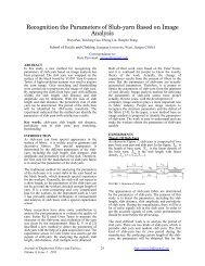
Figure 1 shows a picture of the guarded fricti<strong>on</strong><br />
meter. It is made from a single piece of steel,<br />
measuring 12 cm x 15 cm x 2.5 cm. The outer,<br />
c<strong>on</strong>venti<strong>on</strong>al sled, S, is pulled by a tensi<strong>on</strong> load<br />
transducer (Omegadyne LCFD-50, Sunbury, OH), F c ,<br />
via cord C. A semicircular secti<strong>on</strong> is cut out of the<br />
center of this sled to <str<strong>on</strong>g>for</str<strong>on</strong>g>m the guarded sled, G, which<br />
is pulled by a compressi<strong>on</strong> load transducer<br />
(Omegadyne LC8100-250-25), F g , via a screw that<br />
passes through F g , through a washer, and through a<br />
slot, which allows G to move vertically relative to S.<br />
Appropriate spacing between S and G is maintained<br />
by an additi<strong>on</strong>al washer. Both S and G are made from<br />
the same material and are the same thickness so that<br />
the pressure is the same under both sleds. Additi<strong>on</strong>al<br />
weights can be added to alter the loads and the<br />
pressures. The shape of the inner sled can be chosen<br />
as appropriate <str<strong>on</strong>g>for</str<strong>on</strong>g> the desired test c<strong>on</strong>diti<strong>on</strong>s. In our<br />
instrument, it is semicircular to avoid snagging <strong>on</strong> a<br />
fibrous substrate. The fr<strong>on</strong>t edges of both sleds are<br />
rounded slightly to avoid digging into soft substrates.<br />
A motor (1 rpm, Merkle Korff Industries, Des Plaines,<br />
IL) attached to a 10:1 reducti<strong>on</strong> gearbox (Gam Gear,<br />
Chicago, IL) pulls the compound sled via a cord at a<br />
rate of 5.30 mm/min. The load transducers are read<br />
using an A/D card (CIO-DAS801 from Omega<br />
Engineering, Inc., Stam<str<strong>on</strong>g>for</str<strong>on</strong>g>d, CT) and the data are<br />
collected using LabView (Nati<strong>on</strong>al Instruments,<br />
Austin, TX).<br />
FIGURE 1. The compound sled that <str<strong>on</strong>g>for</str<strong>on</strong>g>ms the guarded fricti<strong>on</strong><br />
meter is shown. The c<strong>on</strong>venti<strong>on</strong>al sled, S, is pulled by cord, C, and<br />
tensi<strong>on</strong> load transducer, T 2 , which measures the <str<strong>on</strong>g>for</str<strong>on</strong>g>ce, F c , required<br />
to pull the compound sled. S, in turn, pulls the guarded sled, G, via<br />
compressi<strong>on</strong> load transducer, T 1 , which measures the <str<strong>on</strong>g>for</str<strong>on</strong>g>ce, F g ,<br />
required to pull <strong>on</strong>ly the guarded sled. The guarded sled floats<br />
freely within the c<strong>on</strong>venti<strong>on</strong>al sled, restrained <strong>on</strong>ly by T 1 .<br />
TEST PROCEDURES<br />
During a test, the sample is placed <strong>on</strong> an aluminum<br />
block and the back edge is clamped in place. The<br />
compound sled is placed <strong>on</strong> a flat surface and the<br />
unloaded readings, R unloaded , <str<strong>on</strong>g>for</str<strong>on</strong>g> the transducers are<br />
read. Next, the load cells are calibrated by<br />
suspending the compound sled via the towing cord<br />
and reading the load cells again to obtain the loaded<br />
reading, R loaded . The calibrati<strong>on</strong> factor is simply:<br />
2