PT Max⢠Belt Trainer Installation, Operation, & Maintenance - Flexco
PT Max⢠Belt Trainer Installation, Operation, & Maintenance - Flexco
PT Max⢠Belt Trainer Installation, Operation, & Maintenance - Flexco

You also want an ePaper? Increase the reach of your titles
YUMPU automatically turns print PDFs into web optimized ePapers that Google loves.
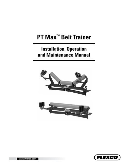
<strong>PT</strong> Max <strong>Belt</strong> <strong>Trainer</strong><br />
<strong>Installation</strong>, <strong>Operation</strong><br />
and <strong>Maintenance</strong> Manual<br />
www.flexco.com<br />
1
<strong>PT</strong> Max <strong>Belt</strong> <strong>Trainer</strong><br />
Serial Number:______________________________________________________________<br />
Purchase Date:_______________________________________________________________<br />
Purchased From:_____________________________________________________________<br />
<strong>Installation</strong> Date:_____________________________________________________________<br />
Serial number information can be found on the Serial Number Label<br />
included in the Information Packet found in the cleaner carton.<br />
This information will be helpful for any future inquiries or questions<br />
about belt cleaner replacement parts, specifications or troubleshooting.<br />
2 <strong>PT</strong> Max <strong>Belt</strong> <strong>Trainer</strong>
Table of Contents<br />
Section 1 - Important Information....................................................................................................4<br />
1.1 General Introduction............................................................................................................................4<br />
1.2 User Benefits..........................................................................................................................................4<br />
1.3 Proper <strong>Belt</strong> <strong>Trainer</strong> Selection...............................................................................................................5<br />
Section 2 - Safety Considerations and Precautions...........................................................................6<br />
2.1 Stationary Conveyors............................................................................................................................6<br />
2.2 Operating Conveyors............................................................................................................................6<br />
Section 3 - Pre-<strong>Installation</strong> Checks and Options...............................................................................7<br />
3.1 Checklist.................................................................................................................................................7<br />
3.2 Optional <strong>Installation</strong> Accessories........................................................................................................7<br />
Section 4 - <strong>Installation</strong> Instructions...................................................................................................8<br />
Section 5 - Pre-<strong>Operation</strong> Checklist and Testing.............................................................................12<br />
5.1 Pre-Op Checklist.................................................................................................................................12<br />
5.2 Test Run the Conveyor.......................................................................................................................12<br />
Section 6 - <strong>Maintenance</strong>...................................................................................................................13<br />
6.1 New <strong>Installation</strong> Inspection...............................................................................................................13<br />
6.2 Routine Visual Inspection..................................................................................................................13<br />
6.3 Routine Physical Inspection..............................................................................................................13<br />
6.4 Roller Replacement Instructions.......................................................................................................14<br />
6.5 Sensor Roller Replacement Instructions..........................................................................................15<br />
6.6 <strong>Maintenance</strong> Log.................................................................................................................................16<br />
6.7 <strong>Maintenance</strong> Checklist.......................................................................................................................17<br />
Section 7 - Troubleshooting.............................................................................................................18<br />
Section 8 - Specs and CAD Drawings...............................................................................................19<br />
8.1 CAD Drawing - <strong>PT</strong> Max Top Side....................................................................................................19<br />
8.2 CAD Drawing - <strong>PT</strong> Max Top Side HD.............................................................................................20<br />
8.3 CAD Drawing - <strong>PT</strong> Max Return.......................................................................................................21<br />
8.4 CAD Drawing - <strong>PT</strong> Max Return HD...............................................................................................22<br />
8.5 <strong>PT</strong> Max Top Side Data Sheet.............................................................................................................23<br />
8.6 <strong>PT</strong> Max Return Side Data Sheet........................................................................................................24<br />
8.7 <strong>PT</strong> Max V-Return Side Data Sheet...................................................................................................25<br />
8.8 <strong>PT</strong> Max Roller Side Data Sheet.........................................................................................................26<br />
Section 9 - Replacement Parts..........................................................................................................27<br />
9.1 Replacement Parts List.......................................................................................................................27<br />
Section 10 - Other <strong>Flexco</strong> Conveyor Products.................................................................................28<br />
3
Section 1 - Important Information<br />
1.1 General Introduction<br />
We at <strong>Flexco</strong> are very pleased that you have selected a <strong>PT</strong> Max <strong>Belt</strong> <strong>Trainer</strong> for your conveyor system.<br />
This manual will help you to understand the installation, operation and maintenance of this product and<br />
assist you in making it work up to its maximum efficiency over its lifetime of service.<br />
It is essential for safe and efficient operation that the information and guidelines presented be properly<br />
understood and implemented. This manual will provide safety precautions, installation instructions,<br />
maintenance procedures and troubleshooting tips. In addition, please follow all standard, approved safety<br />
guidelines when working on your conveyor.<br />
If, however, you have any questions or problems that are not covered, please visit our web site or contact our<br />
Customer Service Department:<br />
Web site: <strong>Flexco</strong>.com<br />
Customer Service: USA: 1-800-541-8028<br />
Australia: 61-2-9680-3322 • China: 86-21-33528388<br />
England: 44-1274-600-942 • Germany: 49-7428-9406-0<br />
India: 91-44-4354-2091 • Mexico: 52-55-5674-5326<br />
Singapore: 65-6281-7278 • South Africa: 27-11-608-4180<br />
Please read this manual thoroughly and pass it on to any others who will be directly responsible for<br />
installation, operation and maintenance of this impact bed. While we have tried to make the installation and<br />
service tasks as easy and simple as possible, this product does however require correct installation and<br />
regular inspection and maintenance to maintain top working condition.<br />
1.2 User Benefits<br />
<strong>Belt</strong> mistracking is a common problem that produces various problems, ranging from belt and structure<br />
damage to product spillage and safety issues. By utilizing the <strong>PT</strong> Max, it is possible to correct a belt that is<br />
mistracking and causing these problems. Multiple units may be required depending on the length of the<br />
mistracking belt.<br />
4 <strong>PT</strong> Max <strong>Belt</strong> <strong>Trainer</strong>
Section 1 - Important Information<br />
1.3 Proper <strong>Belt</strong> <strong>Trainer</strong> Selection<br />
<strong>Belt</strong> Positioner <br />
Selection Guidelines<br />
MODEL<br />
<strong>Belt</strong> Positioner <br />
<strong>PT</strong> Smart <br />
<strong>PT</strong> Smart Underground<br />
<strong>PT</strong> Max Top Side<br />
HD <strong>PT</strong> Max Top Side<br />
<strong>PT</strong> Max Return Side<br />
HD <strong>PT</strong> Max Return Side<br />
APPLICATION RANGE<br />
Return side only, 800 PIW max tension on<br />
Small, Medium and Large; 1200 PIW max<br />
tension on Extra Large.<br />
Also works on reversing belts.<br />
Medium-duty belts up to 1600 PIW max<br />
tension. <strong>Belt</strong> width + 3" idler. <strong>Belt</strong> thickness<br />
1" maximum.<br />
Medium-duty belts up to 1600 PIW max<br />
tension. <strong>Belt</strong> width + 9" idler. <strong>Belt</strong> thickness<br />
1" maximum. Fits underground structure.<br />
Heavy-duty belts up to 3000 PIW max<br />
(generally over 3/4" (19mm) thick)<br />
<strong>Belt</strong> width 24" - 60" (600 - 1500mm)<br />
Heavy-duty belts up to 6000 PIW max<br />
tension. <strong>Belt</strong> width 48" - 84" (1200 - 2100mm)<br />
Heavy-duty, higher tension belts up to 3000<br />
PIW max. (generally up to 1" (25mm) thick)<br />
Heavy-duty belts up to 6000 PIW max<br />
tension. <strong>Belt</strong> width 48" - 84" (1200 - 2100mm)<br />
<strong>PT</strong> Smart <br />
Standard<br />
<strong>PT</strong> Smart <br />
Underground<br />
Structure<br />
<strong>PT</strong> Max <br />
Top Side<br />
<strong>PT</strong> Max <br />
Return Side<br />
CONVEYOR CRITERIA<br />
BELT<br />
POSITIONER <br />
<strong>PT</strong><br />
SMART <br />
<strong>PT</strong> SMART <br />
UNDERGROUND<br />
<strong>PT</strong> MAX <br />
TOP SIDE<br />
HD <strong>PT</strong><br />
MAX <br />
TOP SIDE<br />
<strong>PT</strong> MAX <br />
RETURN<br />
SIDE<br />
Top side mistracking NO NO NO YES YES NO NO<br />
Return side mistracking YES YES YES NO NO YES YES<br />
HD <strong>PT</strong><br />
MAX <br />
RETURN<br />
SIDE<br />
<strong>Belt</strong> mistracking to one side EXCELLENT EXCELLENT EXCELLENT EXCELLENT EXCELLENT EXCELLENT EXCELLENT<br />
<strong>Belt</strong> mistracking to both sides POOR EXCELLENT EXCELLENT EXCELLENT EXCELLENT EXCELLENT EXCELLENT<br />
Inconsistent tracking problem GOOD EXCELLENT EXCELLENT EXCELLENT EXCELLENT EXCELLENT EXCELLENT<br />
<strong>Belt</strong> is cupped (heavy) GOOD GOOD GOOD EXCELLENT EXCELLENT GOOD GOOD<br />
<strong>Belt</strong> has low running tension POOR EXCELLENT EXCELLENT GOOD GOOD GOOD GOOD<br />
<strong>Belt</strong> has medium running tension GOOD EXCELLENT EXCELLENT EXCELLENT EXCELLENT EXCELLENT EXCELLENT<br />
<strong>Belt</strong> has high running tension GOOD GOOD GOOD EXCELLENT EXCELLENT EXCELLENT EXCELLENT<br />
Approx. "upstream" effect* 50' (15 M) 20' (6 M) 20' (6 M) 20' (6 M) 20' (6 M) 20' (6 M) 20' (6 M)<br />
Approx. "downstream" effect* 50' (15 M)<br />
120' - 150'<br />
(36 - 45 M)<br />
120' - 150'<br />
(36 - 45 M)<br />
150' - 200'<br />
(45 - 61 M)<br />
150' - 200'<br />
(45 - 61 M)<br />
150' - 200'<br />
(45 - 61 M)<br />
150' - 200'<br />
(45 - 61 M)<br />
*Typical results; actual results may vary<br />
5
Section 2 - Safety Considerations and Precautions<br />
Before installing and operating the <strong>PT</strong> Max <strong>Belt</strong> <strong>Trainer</strong>, it is important to review and understand the following safety<br />
information.<br />
There are setup, maintenance and operational activities involving both stationary and operating conveyors. Each case<br />
has a safety protocol.<br />
2.1 Stationary Conveyors<br />
The following activities are performed on stationary conveyors:<br />
• <strong>Installation</strong> • Impact bar replacement • Repairs<br />
• Skirt rubber adjustments • Cleaning<br />
!<br />
danger<br />
It is imperative that OSHA/MSHA Lockout/Tagout<br />
(LOTO) regulations, 9 CFR 1910.147, be followed before<br />
undertaking the preceding activities. Failure to use LOTO<br />
exposes workers to uncontrolled behavior of the impact<br />
bed caused by movement of the conveyor belt. Severe<br />
injury or death can result.<br />
Before working:<br />
• Lockout/Tagout the conveyor power source<br />
• Disengage any takeups<br />
• Clear the conveyor belt or clamp securely<br />
in place<br />
!<br />
WARNING<br />
Use Personal Protective Equipment (PPE):<br />
• Safety eyewear<br />
• Hardhats<br />
• Safety footwear<br />
Close quarters and heavy components create a<br />
worksite that compromises a worker’s eyes, feet<br />
and skull.<br />
PPE must be worn to control the foreseeable<br />
hazards associated with conveyor belt<br />
components. Serious injuries can be avoided.<br />
2.2 Operating Conveyors<br />
There are two routine tasks that must be performed while the conveyor is running:<br />
• Inspection of the sealing performance<br />
• Dynamic troubleshooting<br />
!<br />
danger<br />
Every belt conveyor is an in-running nip hazard.<br />
Never touch or prod an operating impact bed.<br />
Conveyor hazards cause instantaneous amputation<br />
and entrapment.<br />
!<br />
WARNING<br />
Never adjust anything on an operating impact bed.<br />
Unforseeable materials falling into the chute can<br />
cause violent movements of the impact bed structure.<br />
Flailing hardware can cause serious injury or death.<br />
!<br />
WARNING<br />
Conveyor chutes contain projectile hazards. Stay as far<br />
from the trainer as practical and use safety eyewear<br />
and headgear. Missiles can inflict serious injury.<br />
6 <strong>PT</strong> Max <strong>Belt</strong> <strong>Trainer</strong>
Section 3 - Pre-installation Checks and Options<br />
3.1 Checklist<br />
• Check the model and size of the belt trainer. Is it the right one for your beltline?<br />
• Check the <strong>PT</strong> Max to be sure all the parts are included in the shipment.<br />
• Find the Information Packet in the shipment.<br />
• Review the “Tools Needed” section on the front of the installation instructions.<br />
• Prepare the conveyor site:<br />
- Identify the point(s) of mistracking, expecting 150' - 200' (45-61M) of<br />
downstream influence.<br />
- Position the unit 20' after the start of the mistracking.<br />
- Identify the existing idler set where <strong>PT</strong> Max will be installed<br />
- Remove old tracking devices.<br />
3.2 Optional <strong>Installation</strong> Accessories<br />
Optional tools can make the installation of the <strong>PT</strong> Max <strong>Belt</strong> <strong>Trainer</strong> easier and faster.<br />
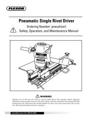
Flex-Lifter Conveyor <strong>Belt</strong> Lifter<br />
Ordering<br />
Description<br />
Number<br />
Item<br />
Code<br />
Medium Flex-Lifter 36" - 60" (900 - 1500 mm) FL-M 76469<br />
Large Flex-Lifter 48" - 72" (1200 - 1800 mm) FL-L 76470<br />
XL Flex-Lifter 72" - 96" (1800-2400 mm) FL-XL 76983<br />
Flex-Lifter Conveyor <strong>Belt</strong> Lifter<br />
The <strong>Flexco</strong> Flex-Lifter makes the job of lifting the<br />
conveyor belt easy and safe. Using two Flex-Lifters,<br />
the belt can be quickly lifted out of the way to install<br />
the <strong>PT</strong> Smart. The Flex-Lifter has the highest safe<br />
lift rating available at 4000 lbs. (1810 kg) for Medium<br />
and Large, and 6000 lbs. (2750kg) for XL. And it’s<br />
versatile. It can also be used to lift topside or return<br />
side belt for splicing, roller replacement or other<br />
maintenance jobs. Available in three sizes: Medium<br />
for belt widths 36" - 60" (900 - 1500mm), Large for<br />
belt widths 48" - 72" (1200 - 1800mm), and XL for<br />
belt widths 72" - 96" (1800 - 2400mm).<br />
7
Section 4 - <strong>Installation</strong> Instructions - <strong>PT</strong> Max<br />
Sensor Rollers<br />
Swivel Mount<br />
Adjusting Arm<br />
Lock Bolt<br />
Adjusting Arm<br />
Top Frame<br />
Sensor Roller Arm<br />
Site-Supplied Roller<br />
<strong>PT</strong> Max Top Side<br />
Adjusting Arm<br />
Lock Nuts<br />
Sensor Roller<br />
Retaining Bolts<br />
Swivel Mount<br />
Retaining Washer<br />
and Pin<br />
<strong>Belt</strong> Direction Label<br />
Side Track<br />
Lock Bolt<br />
Bottom Frame<br />
Mounting<br />
Bracket<br />
Sensor Rollers<br />
Center Roller<br />
<strong>PT</strong> Max Return Side<br />
Tension<br />
Spacer<br />
Site-Supplied Roller<br />
Mounting<br />
Spacer<br />
Swivel<br />
Mount<br />
Sensor Roller<br />
Retaining Bolts<br />
Adjusting Arm<br />
Lock Bolt<br />
Top Frame<br />
Bottom Frame<br />
Center<br />
Roller<br />
Swivel Mount Retaining<br />
Washer and Pin<br />
Side Track<br />
Lock Bolt<br />
Tension<br />
Spacer<br />
Mounting<br />
Bracket<br />
Physically lock out and tag the conveyor at the power source before you<br />
begin cleaner installation.<br />
Before You Begin:<br />
• These instructions are designed to be used when installing either the Top<br />
Side or the Return Side models.<br />
• A serial number plate is located on the top frame of the unit. This serial<br />
number identifies the specifications of this custom-built unit. Please use<br />
this number in any correspondence.<br />
• The <strong>PT</strong> Max has been purposely designed with a much heavier<br />
construction than conventional tracking devices. It is, in most cases,<br />
TOO HEAVY to manage manually. Please use the necessary mechanical<br />
lifting equipment (crane, come-alongs, etc.) for safe installation.<br />
• After the roller(s) (troughing or return) have been installed in the trainer,<br />
secure the roller(s) per the instructions to prevent them from falling out<br />
while the unit is being lifted into position on the conveyor.<br />
• The trainer should not be positioned closer than 20 feet (6M) from the<br />
tail pulley, take-up pulleys, or head pulley<br />
• Follow all safety precautions when using a cutting torch.<br />
Tools Needed:<br />
• Tape Measure<br />
• 3/4" Wrench<br />
• Medium or Large Adjustable<br />
Wrench<br />
• (2) Pipe Wrenches<br />
• Power Drill (1/4" Drill Bit Is<br />
Supplied)<br />
• Cutting Torch<br />
• (2) Come-Alongs (3/4 Ton<br />
Minimum)<br />
• Any necessary equipment<br />
for moving and lifting heavy<br />
components<br />
8 <strong>PT</strong> Max <strong>Belt</strong> <strong>Trainer</strong>
Section 4 - <strong>Installation</strong> Instructions<br />
Conveyor Site Preparation<br />
1. Lift the belt where the trainer will be installed. At the site where the<br />
trainer will be installed, lift the belt 2" (50mm) off the troughing idler<br />
set or the return roller that will be replaced. CAUTION: Some lifting<br />
equipment or tools may be required depending upon the weight of<br />
the belt.<br />
2. Remove the existing idler. Unbolt the troughing idler set or return<br />
roller and mounting brackets and lift it out of the conveyor. Set the<br />
unit nearby so the rollers can be used in the new trainer to be installed.<br />
3. Verify clearance for the lower sections of the <strong>PT</strong> Max where it is to<br />
be located on the conveyor (Fig. 1). Remove any obstructions such as<br />
structure supports or separation pans.<br />
<strong>PT</strong> Max Top Side<br />
Clearance needed<br />
for installation<br />
<strong>PT</strong> Max Return Side<br />
Clearance<br />
needed for<br />
installation<br />
Fig. 1<br />
<strong>PT</strong> Max Preparation And <strong>Installation</strong> On The Conveyor<br />
Shipping Position<br />
ADJUSTING<br />
ARM NUT<br />
LOCK<br />
WASHER<br />
Fig. 2<br />
Remove sensor rollers<br />
1. Remove the sensor rollers from the unit (Fig. 2). Remove the adjusting<br />
arm nuts and lock washers, pull the dual rollers out of the unit, and set<br />
aside for installation after the unit is installed on the conveyor.<br />
2. Install the troughing rollers or return roller (Fig. 3). Use the rollers<br />
from the set removed during site preparation or from on-site inventory.<br />
Important: The <strong>PT</strong> Max has been expressly designed to use the same<br />
rollers that are currently in use on the conveyor. For maximum results<br />
the rollers must match the type in use.<br />
Correct<br />
Incorrect<br />
(not fully<br />
seated in<br />
retainer)<br />
Plastic Ties<br />
Fig. 3<br />
Fig. 4<br />
3. Secure the roller(s) in the unit. Use the plastic ties supplied to insure the<br />
rollers do not become dislodged when the unit is moved or lifted (Fig. 4).<br />
Failure to secure the roller(s) may result in serious injury if a roller falls out.<br />
4. Move the unit into position on the conveyor. Locate the trainer on the<br />
conveyor where the idler was removed. Check that the belt direction labels<br />
are pointing in the direction of belt travel (Fig. 5).<br />
BELT<br />
DIRECTION<br />
LABEL<br />
Fig. 5<br />
9
Section 4 - <strong>Installation</strong> Instructions<br />
5. Secure to the conveyor structure.<br />
Square the unit with the structure.<br />
Insert the tension spacer (Fig.<br />
6). Mounting spacers are also<br />
required on Return Side trainers<br />
(Fig. 7). Secure the unit to the<br />
structure with mounting bolts,<br />
lock washers and nuts and tighten.<br />
6. Lower the belt onto the trainer.<br />
Secure with mounting<br />
bolts, lock washers<br />
& nuts<br />
TENSION<br />
SPACER<br />
Fig. 6 Top Side Fig. 7<br />
Secure with mounting<br />
bolts, lock washers<br />
& nuts<br />
MOUNTING<br />
SPACER<br />
TENSION<br />
SPACER<br />
Return Side<br />
SENSOR ROLLERS<br />
SENSOR<br />
ROLLER<br />
ARM<br />
Adjustment To The <strong>Belt</strong><br />
1. Insert sensor rollers into the unit. Reinsert the sensor roller assemblies into<br />
the sensor roller arms in the working (outward) position (Fig. 8). Reassemble<br />
the lock washers and nuts finger tight, allowing the sensor rollers to hang down.<br />
LOCK<br />
WASHER<br />
Fig. 8<br />
NUT<br />
2. Remove the side track lock bolt (Fig. 9).<br />
This bolt keeps the unit from pivoting during<br />
installation. It must now be removed to allow<br />
the unit to pivot and tilt for belt training.<br />
3. Check for clearance as the unit moves. Pivot the unit in both directions to<br />
ensure there are no obstructions to movement. Note: It may be difficult to<br />
manually move the heavy-duty or super-duty models due to the weight of the belt.<br />
4. Adjust unit to the belt. NOTE: Final adjustments of the trainer to the beltline<br />
depend on where the belt is currently running on the structure. If the belt<br />
is running centered on the structure see Option 1, if it is not centered on the<br />
structure use the adjustment steps in Option 2.<br />
Option 1 (<strong>Belt</strong> centered on structure): Position the sensor rollers to the belt<br />
edges. Rotate the sensor rollers into the upright position and adjust to ¾" (19mm)<br />
from the belt edges by using the adjusting arm nuts (Fig. 10).<br />
Option 2 (<strong>Belt</strong> not centered on structure): Pivot the unit forward on the side<br />
the belt is running off (Fig. 11). Rotate the sensor rollers into the upright position<br />
and adjust the adjusting arms so the sensor rollers on the side running off are just<br />
touching the belt edge and the opposite side sensor rollers have a 1-1/2" (38mm)<br />
clearance gap (Fig. 12).<br />
Fig. 9<br />
ADJUSTING<br />
ARM LOCK<br />
NUTS<br />
<strong>Belt</strong><br />
Fig. 10<br />
SIDE TRACK LOCK<br />
BOLT<br />
3/4"<br />
(19mm)<br />
Pivot unit<br />
forward on side<br />
running off<br />
<strong>Belt</strong> Direction<br />
Contact<br />
<strong>Belt</strong> Direction<br />
Fig. 11<br />
1-1/2"<br />
(38mm)<br />
Fig. 12<br />
10 <strong>PT</strong> Max <strong>Belt</strong> <strong>Trainer</strong>
Section 4 - <strong>Installation</strong> Instructions<br />
A<br />
A<br />
"A" dims<br />
equal within ½"<br />
(13mm)<br />
ADJUSTING<br />
ARM<br />
RETAINING<br />
WASHER<br />
SWIVEL<br />
MOUNT<br />
Rotate 180°<br />
RETAINING PIN<br />
Fig. 13 Fig. 14<br />
Fig. 15<br />
Insert shims (washers) in<br />
front or rear as needed<br />
5. Check the belt’s running location on the face of the sensor rollers. For maximum results, the belt’s line of travel<br />
must be centered on the face of the sensor rollers within ½" (13mm) (Fig. 13).<br />
If the belt is not centered:<br />
Option A. Lower the sensor rollers to center on the belt, or for more clearance if needed (this will lower the<br />
sensor rollers 1" (25mm)). Remove the swivel mount retaining pin and retaining washer and slide the swivel<br />
mount out of the adjusting arm. Rotate the adjusting arm 180° and reinsert the swivel mount, retaining washers<br />
and retaining pin (Fig. 14).<br />
Option B. Shim the unit to lower or raise the sensor rollers in relation to the belt. Insert shims (washers or other<br />
material--not supplied) under either the front or rear mounting bolt on both sides of the unit (Fig. 15).<br />
6. Run the conveyor to verify the training results. If adjustment is needed, adjust one set of sensor rollers in and<br />
the opposite side out an equal amount.<br />
ADJUSTING ARM<br />
LOCK BOLT<br />
7. Lock the adjusting arms in place (Fig. 16). Once the training path has been<br />
set and confirmed, loosen the adjusting arm lock bolt jam nut and tighten the<br />
adjusting arm lock bolt. Re-tighten the adjusting arm lock bolt jam nut. Repeat<br />
on opposite side.<br />
ADJUSTING ARM LOCK<br />
BOLT JAM NUT<br />
Fig. 16<br />
11
Section 5 - Pre-<strong>Operation</strong> Checklist and Testing<br />
5.1 Pre-Op Checklist<br />
• Recheck that all fasteners are tight<br />
• Apply all supplied labels<br />
• Be sure that all installation materials and tools have been removed from the belt and conveyor area<br />
5.2 Test Run the Conveyor<br />
• Run the conveyor for at least 15 minutes and confirm the belt is tracking properly.<br />
• If belt is still mistracking too far to one side, bring that sensor roller in toward the center. Make<br />
adjustments of 1/4"(6mm) at a time (Fig. 1). Do not pinch the belt between the rollers - rollers<br />
overall should be 1-1/2" (38mm) wider than the belt (Fig. 2).<br />
Mistracking side<br />
Top View<br />
<strong>Belt</strong><br />
(Roller)<br />
Move Sensor Roller<br />
1/4" (6mm) increments<br />
Fig. 1<br />
<strong>Belt</strong> Direction<br />
Move opposite Sensor<br />
Roller 1-1/2" (38mm)<br />
away from belt<br />
OR<br />
3/4" (19mm)<br />
each side<br />
(both sensor rollers<br />
touching the belt)<br />
1-1/2" (38mm)<br />
Fig. 2<br />
Incorrect<br />
Correct<br />
Correct<br />
12 <strong>PT</strong> Max <strong>Belt</strong> <strong>Trainer</strong>
Section 6 - <strong>Maintenance</strong><br />
<strong>Flexco</strong> belt trainers are designed to operate with minimum maintenance. However, to maintain superior<br />
performance some service is required. When the trainer is installed a regular maintenance program should be set<br />
up. This program will ensure that the trainer operates at optimal efficiency, and problems can be identified and<br />
fixed before any damage is done to the belt, the trainer, other conveyor components, or structure.<br />
All safety procedures for inspection of equipment (stationary or operating) must be observed. The <strong>PT</strong> Max is in<br />
direct contact with the moving belt. Only visual observations can be made while the belt is running. Service tasks<br />
can be done only with the conveyor stopped and by observing the correct lockout/tagout procedures.<br />
6.1 New <strong>Installation</strong> Inspection<br />
After the <strong>PT</strong> Max has run for 15 minutes a visual inspection should be made to ensure the trainer is<br />
performing properly. Make adjustments as needed.<br />
6.2 Routine Visual Inspection (every 2-4 weeks)<br />
A visual inspection of the <strong>PT</strong> Max can determine:<br />
• If the belt is tracking as required<br />
• If the trainer is moving freely<br />
• If the main frame is free of material and rolling properly<br />
• If there is damage to the main frame or other components<br />
• If the sensor rollers are turning freely and without damage<br />
If any of the above conditions exist, a determination should be made on when the conveyor can be<br />
stopped for trainer maintenance.<br />
6.3 Routine Physical Inspection (every 6-8 weeks)<br />
When the conveyor is not in operation and properly locked and tagged out, a physical inspection of the<br />
trainer to perform the following tasks:<br />
• Clean material buildup off the trainer and components.<br />
• Closely inspect both sensor rollers for free movement and wear. Replace if needed.<br />
• Closely inspect main roller for free movement and wear. Replace if needed.<br />
• Pivot unit to ensure full and easy movement.<br />
• Closely inspect complete unit for damage.<br />
• Inspect all fasteners for tightness and wear. Tighten or replace if needed.<br />
• When maintenance tasks are completed, test run the conveyor to ensure the trainer is<br />
performing properly.<br />
13
Section 6 - <strong>Maintenance</strong><br />
6.4 Roller Replacement Instructions<br />
<strong>PT</strong> Max Top Side<br />
Site-Supplied Roller<br />
<strong>PT</strong> Max Return Side<br />
Site-Supplied Roller<br />
Physically lock out and tag the conveyor at the power source before you<br />
begin cleaner installation.<br />
CAUTION: Components may be heavy. Use safety-approved lifting procedures.<br />
1. Remove tension from belt. Use a Flex-Lifter or other<br />
appropriate lifting equipment to lift the belt approx.<br />
3" (75mm) off the trainer.<br />
2. Remove roller(s) per manufacturers specifications<br />
(site supplied).<br />
3. Install new roller(s) per manufacturers specifications<br />
(site-supplied). Confirm roller turns smoothly.<br />
4. Lower the belt. Ensure belt completely contacts<br />
roller(s). Shim the unit to raise or lower in relation to<br />
the belt if there is not good contact (Fig. 1). Tighten<br />
all bolts.<br />
5. Go to page 10 “Adjustment to the <strong>Belt</strong>.”<br />
Fig. 1<br />
<strong>Belt</strong><br />
Roller<br />
INCORRECT - raise roller<br />
<strong>Belt</strong><br />
Roller<br />
CORRECT<br />
14 <strong>PT</strong> Max <strong>Belt</strong> <strong>Trainer</strong>
Section 6 - <strong>Maintenance</strong><br />
6.5 Sensor Roller Replacement Instructions<br />
Dual Rollers<br />
<strong>PT</strong> Max Top Side<br />
Dual Rollers<br />
<strong>PT</strong> Max Return Side<br />
Dual Rollers<br />
Dual Rollers<br />
Physically lock out and tag the conveyor at the power source before you<br />
begin cleaner installation.<br />
1. Loosen “A” bolts, turn “B” nut to the end of the rod then turn “C” nut to move sensor rollers away from<br />
the belt (Fig. 1).<br />
2. Loosen set screws at base of sensor rollers and remove from adjuster arm (Fig. 2).<br />
3. Install new sensor rollers, retighten set screws.<br />
4. Go to page 10 “Adjustment to the <strong>Belt</strong>.”<br />
Sensor Roller<br />
Loosen Set Screws<br />
“C” Nut<br />
“B” Nut<br />
Fig. 1<br />
“A” Bolts<br />
Fig. 2<br />
15
Section 6 - <strong>Maintenance</strong><br />
6.6 <strong>Maintenance</strong> Log<br />
Conveyor Name/No.<br />
Date: Work done by: Service Quote #<br />
Activity:<br />
Date: Work done by: Service Quote #<br />
Activity:<br />
Date: Work done by: Service Quote #<br />
Activity:<br />
Date: Work done by: Service Quote #<br />
Activity:<br />
Date: Work done by: Service Quote #<br />
Activity:<br />
Date: Work done by: Service Quote #<br />
Activity:<br />
Date: Work done by: Service Quote #<br />
Activity:<br />
16 <strong>PT</strong> Max <strong>Belt</strong> <strong>Trainer</strong>
Section 6 - <strong>Maintenance</strong><br />
6.7 <strong>Belt</strong> <strong>Trainer</strong> <strong>Maintenance</strong> Checklist<br />
<strong>PT</strong> Max:<br />
Serial Number:<br />
<strong>Belt</strong>line Information:<br />
<strong>Belt</strong>line Number:<br />
<strong>Belt</strong> Condition:<br />
<strong>Belt</strong> Width: 24" 30" 36" 42" 48" 54" 60" 72" 84"<br />
<strong>Belt</strong> Speed<br />
<strong>Belt</strong> Thickness<br />
Idler Rollers Life:<br />
Date rollers installed: Date rollers inspected: Estimated roller life:<br />
Roller condition:<br />
Sensor Rollers Life (Right Side):<br />
Date rollers installed: Date rollers inspected: Estimated roller life:<br />
Roller condition:<br />
Sensor Rollers Life (Left Side):<br />
Date rollers installed: Date rollers inspected: Estimated roller life:<br />
Roller condition:<br />
<strong>PT</strong> Max Frame Condition:<br />
Good Bent Rusted<br />
Overall <strong>PT</strong> Max Performance:<br />
Appearance:<br />
Location:<br />
<strong>Maintenance</strong>:<br />
Performance:<br />
(Rate the following 1 - 5; 1=very poor, 5=very good)<br />
Comments:<br />
Comments:<br />
Comments:<br />
Comments:<br />
Other Comments:<br />
17
Section 7 - Troubleshooting<br />
Problem Possible Cause Possible Solutions<br />
Little to no effect on trouble area<br />
of belt<br />
Unit installed in wrong location<br />
Incorrect tension on unit<br />
Unit mis-adjusted<br />
Buildup on main roller<br />
Relocate unit 20' (6M) after start of problem area of belt<br />
Increase height of unit to provide 1/2" - 1" (13-25mm) lift<br />
on belt<br />
Adjust sensor roller to provide more activation of unit<br />
Clean unit<br />
<strong>Belt</strong> not correcting enough Unit mis-adjusted Adjust sensor roll to provide more activation of unit<br />
<strong>Belt</strong> moving over too much Unit mis-adjusted Adjust sensor roll to provide less activation of unit<br />
<strong>Belt</strong> is jumping sensor roll<br />
<strong>Belt</strong> contacting both side sensors<br />
Unit located too low in structure<br />
Unit mis-adjusted<br />
Unit does not pivot Buildup of material Clean unit<br />
Increase height of unit to provide 1/2" - 1" (13-25mm) lift<br />
on belt<br />
Adjust sensors to provide the 1" (25mm) clearance so both<br />
sensors do not touch belt<br />
Main roller not turning<br />
Buildup on main roller<br />
Main roller bearing bad<br />
Clean unit<br />
Replace main roller<br />
18 <strong>PT</strong> Max <strong>Belt</strong> <strong>Trainer</strong>
Section 8 - Specs and CAD Drawings<br />
8.1 CAD Drawing - <strong>PT</strong> Max Top Side<br />
19
Section 8 - Specs and CAD Drawings<br />
8.2 CAD Drawing - <strong>PT</strong> Max Top Side HD<br />
20 <strong>PT</strong> Max <strong>Belt</strong> <strong>Trainer</strong>
Section 8 - Specs and CAD Drawings<br />
8.3 CAD Drawing - <strong>PT</strong> Max Return<br />
21
Section 8 - Specs and CAD Drawings<br />
8.4 CAD Drawing - <strong>PT</strong> Max Return HD<br />
22 <strong>PT</strong> Max <strong>Belt</strong> <strong>Trainer</strong>
Section 8 - Specs and CAD Drawings<br />
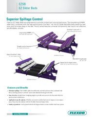
8.5 <strong>PT</strong> Max Top Side Data Sheet<br />
<strong>PT</strong> Max Top Side Data Sheet<br />
V<br />
Distance between<br />
troughing sets<br />
Q<br />
± 1/8"<br />
J<br />
± 1/4"<br />
Instructions:<br />
1. Check troughing set type<br />
and indicate troughing<br />
angle in Box 1.<br />
2. Circle the conveyor<br />
structure type and add<br />
dimensions in Box 2.<br />
3. Fill in specs in Box 3.<br />
4. Fax to (616) 459-4976<br />
attn: Ryan Holowaty<br />
P<br />
± 1/4"<br />
Inner dimension of structure<br />
Show structure details (Box 2)<br />
1. 2.<br />
Troughing<br />
set type<br />
Examples of Structure Cross Sections<br />
Inline Roller<br />
Offset Roller<br />
o<br />
Troughing<br />
Angle<br />
Under Skirting<br />
X1074 Revised 3-12<br />
Questions? Contact Ryan Holowaty at (616) 242-1724<br />
or email rholowaty@flexco.com<br />
3.<br />
Ø<br />
M<br />
N<br />
Mounting Plate<br />
± 1/4"<br />
K<br />
± 1/2"<br />
L<br />
<strong>Belt</strong> Separation<br />
(Top belt to bottom belt)<br />
Conveyor Structure<br />
Dimensions<br />
J<br />
K<br />
L<br />
M<br />
N<br />
P<br />
Q<br />
V<br />
23
Section 8 - Specs and CAD Drawings<br />
8.6 <strong>PT</strong> Max Return Side Data Sheet<br />
<strong>PT</strong> Max Return Side Data Sheet<br />
Show structure details (Box 1)<br />
M<br />
Ø<br />
N<br />
Mounting<br />
Plate<br />
V<br />
Distance between<br />
return rollers<br />
P<br />
Inner dimension of structure<br />
R<br />
Bottom of structure<br />
to top of roller<br />
±1/8”<br />
Instructions:<br />
1. Circle the conveyor<br />
structure type and add<br />
dimensions in Box 1.<br />
2. Fill in specs in Box 2.<br />
3. Fax to (616) 459-4976<br />
attn: Ryan Holowaty<br />
±1/8”<br />
Q<br />
Ground Level<br />
±1/2”<br />
S<br />
If greater than 30”,<br />
just fill in dimension<br />
as 30”<br />
1. Examples of Structure Cross Sections<br />
2.<br />
Conveyor structure<br />
dimensions<br />
X1073 Revised 3-12<br />
Questions? Contact Ryan Holowaty at (616) 242-1724<br />
or email rholowaty@flexco.com<br />
24 <strong>PT</strong> Max <strong>Belt</strong> <strong>Trainer</strong>
Section 8 - Specs and CAD Drawings<br />
8.7 <strong>PT</strong> Max V-Return Side Data Sheet<br />
<strong>PT</strong> Max V-Return Side Data Sheet<br />
Show structure details (Box 2)<br />
M Ø<br />
Instructions:<br />
1. Check return idler type<br />
in Box 1.<br />
2. Circle the conveyor<br />
structure type and add<br />
dimensions in Box 2.<br />
3. Fill in specs in Box 3.<br />
4. Fax to (616) 459-4976<br />
attn: Ryan Holowaty<br />
T<br />
P<br />
Inner dimension of structure<br />
Q<br />
±1/8”<br />
Ground Level<br />
N<br />
U<br />
Mounting Plate<br />
R<br />
±1/2”<br />
S<br />
V<br />
Distance between<br />
return rollers<br />
Bottom of structure<br />
to top of roller<br />
±1/8”<br />
If greater than 30”,<br />
just fill in dimension<br />
as 30”<br />
1. 2. Examples of Structure Cross Sections<br />
3.<br />
Return idler<br />
type:<br />
Conveyor structure<br />
dimensions<br />
V-Return<br />
° Trough Angle<br />
X1155 Revised 3-12<br />
Questions? Contact Ryan Holowaty at (616) 242-1724<br />
or email rholowaty@flexco.com<br />
25
Section 8 - Specs and CAD Drawings<br />
8.8 <strong>PT</strong> Max Roller Side Data Sheet<br />
Instructions:<br />
1. Circle idler cap type in Box 1.<br />
2. Fill in specs in Box 2.<br />
3. Fill in conveyor information in Box 3.<br />
4. Fax to (616) 459-4976 attn: Ryan Holowaty<br />
<strong>PT</strong> Max Roller Data Sheet<br />
±1/32"<br />
±1/32"<br />
G* C<br />
1. Idler Cap Type<br />
Ø ±1/32"<br />
B<br />
A<br />
Diameter<br />
F*<br />
F F<br />
G<br />
G<br />
F<br />
±1/16"<br />
D<br />
±1/8"<br />
E<br />
Width across flats<br />
+0<br />
-1/32<br />
*See Idler Cap details for<br />
specific measurements<br />
needed for F & G<br />
F F<br />
G<br />
F<br />
G<br />
Questions? Contact Ryan Holowaty at (616) 242-1724<br />
or email rholowaty@flexco.com<br />
2. Roller Dimensions 3.<br />
Roller dimensions are easily measured from a<br />
spare roller not installed in the conveyor system.<br />
A<br />
B<br />
C<br />
D<br />
E<br />
F<br />
G<br />
Conveyor Information<br />
Conveyor Name<br />
CEMA Rating (if known)<br />
<strong>Belt</strong> Thickness<br />
<strong>Belt</strong> Width<br />
Troughing Angle<br />
Return Roller Angle<br />
Material Carried<br />
Number of Rolls in Troughing Set<br />
Equal/Unequal Trough Rolls<br />
(if unequal, do this sheet for each size)<br />
Roller Brand<br />
X1075 Revised 3-12<br />
26 <strong>PT</strong> Max <strong>Belt</strong> <strong>Trainer</strong>
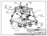
Section 9 - Replacement Parts<br />
9.1 Replacement Parts List<br />
4<br />
1<br />
7a<br />
7<br />
6<br />
2<br />
3 3a<br />
5<br />
9<br />
8<br />
8a<br />
Replacement Parts<br />
Ref<br />
Description<br />
<strong>Belt</strong> Width<br />
in. mm<br />
Ordering<br />
Number<br />
Item<br />
Code<br />
1 Sensor Roller* (3" solid roller) (1 ea.) 30-84 750-2100 MSR 74914<br />
2 Swivel Mount Kit* 30-84 750-2100 PMSMK 74916<br />
3 Adjusting Arm Kit* 30-60 750-1500 MAK 74918<br />
3a HD Adjusting Arm Kit* 54-84 1350-2100 MAKHD 74919<br />
4 Outer Roller Kit*<br />
(incl. 2 rollers, roller thimbles and bolts, nuts and washers)<br />
30-84 750-2100 MORK 74921<br />
5 Center Roller Kit*<br />
(incl. 2 rollers, 2 washers, and 2 cotter pins)<br />
30-84 750-2100 MCRK 74923<br />
6 Center Bearing* 30-84 750-2100 MCB 74925<br />
7 Center Shaft Spacer Kit (incl. 2 spacers) 30-60 750-1500 MCSK 74927<br />
7a HD Center Shaft Spacer Kit (incl. 2 spacers) 54-84 1350-2100 MCSKHD 74928<br />
8 Center Shaft 30-60 750-1500 MCS 74930<br />
8a HD Center Shaft 54-84 1350-2100 MCSHD 74931<br />
9 Frame Arm Set Screw Kit<br />
(incl. 2 set screws and 2 jam nuts)<br />
30-120 750-3000 MFASK 75531<br />
- Center Bearing Kit (incl. 1 ea. items 5, 6, 7, 8) 30-60 750-1500 MCBK 76025<br />
- HD Center Bearing Kit (incl. 1 ea. items 5, 6, 7a, 8a) 54-84 1350-2100 MCBKHD 76026<br />
*Hardware included<br />
Lead time: 1 working day<br />
27
Section 10 - Other <strong>Flexco</strong> Conveyor Products<br />
<strong>Flexco</strong> provides many conveyor products that help your conveyors to run more efficiently and safely. These components<br />
solve typical conveyor problems and improve productivity. Here is a quick overview on just a few of them:<br />
EZP1 Precleaner<br />
Flex-Lok Skirt Clamps<br />
• Patented ConShear blade renews its cleaning edge as it wears<br />
• Visual Tension Check for optimal blade tensioning and<br />
simple retensioning<br />
• Quick and easy one-pin blade replacement<br />
• Material Path Option for optimal cleaning and reduced<br />
maintenance<br />
• Eliminates transfer zone spillage<br />
• Interlocking design for easy installation and oneperson<br />
maintenance<br />
• Unique wedge pin holds rubber securely in place<br />
and is easy to adjust<br />
• Available in various models and in stainless steel<br />
MMP Precleaner<br />
<strong>PT</strong> Smart <strong>Belt</strong> <strong>Trainer</strong><br />
• Extra cleaning power for tough applications<br />
• 10" TuffShear blade provides increased blade-to-belt tension<br />
• A 3-piece telescoping pole is lighter to lift and easier to install<br />
• Dual Quick-Mount Tensioners ensure optimal tension<br />
throughout the life of the blade<br />
• Patented “pivot & tilt” design for superior training action<br />
• Pivot point guaranteed not to freeze or seize up<br />
• Available for return side belts<br />
MHS Secondary Cleaner with Service<br />
Advantage Cartridge<br />
<strong>Belt</strong> Plows<br />
• An easy slide-out cartridge for service<br />
• Cartridge design to speed up blade-change maintenance<br />
• Patented PowerFlex Cushions for superior cleaning<br />
performance<br />
• Compatible with <strong>Flexco</strong> mechanical splices<br />
• A belt cleaner for the tail pulley<br />
• Exclusive blade design quickly spirals debris off the belt<br />
• Economical and easy to service<br />
• Available in vee or diagonal models<br />
28 <strong>PT</strong> Max <strong>Belt</strong> <strong>Trainer</strong>
30 <strong>PT</strong> Max <strong>Belt</strong> <strong>Trainer</strong>
The <strong>Flexco</strong> Vision<br />
To become the leader in maximising<br />
belt conveyor productivity for our customers worldwide<br />
through superior service and innovation.<br />
1995 Oak Industrial Drive NE • Grand Rapids, MI 49505 U.S.A.<br />
Tel: (616)-459-3196 • Fax: (616)-459-4976 • E-mail: info@flexco.com • Web: www.flexco.com<br />
Australia: 61-2-9680-3322 • China: 86-21-33528388 • England: 44-1274-600-942 • Germany: 49-7428-9406-0<br />
India: 91-44-4354-2091 • Mexico: 52 -55- 5674-5326 • Singapore: 65-6281-7278 • South Africa: 27-11-608-4180<br />
32 ©2012 Flexible Steel Lacing <strong>PT</strong> Max Company. <strong>Belt</strong> 4/12. <strong>Trainer</strong> X2406