Kroma Telecom, Manual for BM5414 and BM5420
Kroma Telecom, Manual for BM5414 and BM5420
Kroma Telecom, Manual for BM5414 and BM5420

Create successful ePaper yourself
Turn your PDF publications into a flip-book with our unique Google optimized e-Paper software.
Professional Monitors 14” & 20”<br />
<strong>BM5414</strong>/<strong>BM5420</strong><br />
User <strong>Manual</strong><br />
<strong>BM5414</strong>/20D11<br />
Edición 01<br />
June 2002<br />
KROMA T E L E C O M<br />
Pol. Ind. Alcobendas - C/ La Granja, 80<br />
28108 Madrid - Spain<br />
Tel. (34-91) 661 45 14<br />
Fax. (34-91) 661 58 75<br />
e-mail: sales@kromatelecom.com<br />
www.kromatelecom.com
KROMA TELECOM<br />
PROFESSIONAL MONITORS <strong>BM5414</strong>/20<br />
SAFETY INFORMATION<br />
WARNING: This product includes critical<br />
mechanical <strong>and</strong> electrical parts which are<br />
essential <strong>for</strong> X-Radiation safety.<br />
For continued safety replace critical components<br />
indicated in the service schematic only with exact<br />
replacement parts given in the parts list of<br />
service <strong>Manual</strong>.<br />
Operating high voltage <strong>for</strong> this product is 16 Kv.<br />
At minimum brightness. Refer to service manual<br />
<strong>for</strong> measurement procedures <strong>and</strong> proper service<br />
adjustments.<br />
WARNING: Electric shock or fire hazard can be<br />
caused if critical components are replaced by non<br />
con<strong>for</strong>m components. Refer to parts list of service<br />
manual.<br />
CAUTION: High vacuum tube is dangerous to<br />
h<strong>and</strong>le refer replacement to qualified personnel.<br />
Replace with a tube of the same type <strong>for</strong> continued<br />
safety.<br />
<strong>BM5414</strong>/20<br />
1
KROMA TELECOM<br />
PROFESSIONAL MONITORS <strong>BM5414</strong>/20<br />
INDEX<br />
1. INTRODUCTION.................................................................................................................................1<br />
1.1. APLICATIONS ..................................................................................................................................1<br />
1.1.1. FEATURES..............................................................................................................................1<br />
1.1.2. PICTURE TUBE......................................................................................................................1<br />
1.1.3. COLOUR STABILITY..............................................................................................................1<br />
1.1.4. FLEXIBILITY ..........................................................................................................................1<br />
1.1.5. AUTO SETUP SYSTEM ..........................................................................................................2<br />
1.1.6. REMOTE CONTROL .............................................................................................................2<br />
1.1.7. MENU......................................................................................................................................2<br />
1.1.8. NORMAL SIZE, UNDERSCAN AND 16:9..............................................................................2<br />
1.1.9. MEMORIES.............................................................................................................................2<br />
1.2. TECHNICAL SPECIFICATIONS ..............................................................................................3<br />
1.2.1. SCAN & SYNC.........................................................................................................................3<br />
1.2.2. PICTURE DISPLAY ................................................................................................................3<br />
1.2.3. CRT..........................................................................................................................................3<br />
1.2.4. DECODER PAL / NTSC PERFORMANCE ............................................................................3<br />
1.2.5. LUMINANCE ..........................................................................................................................4<br />
1.2.6. CHROMINANCE.....................................................................................................................4<br />
1.2.7. GENERAL ...............................................................................................................................4<br />
1.3. INSTALLATION ..........................................................................................................................5<br />
1.3.1. Incoming Inspection ................................................................................................................5<br />
1.3.2. Safety In<strong>for</strong>mation ...................................................................................................................5<br />
1.3.3. Connection to the Main ...........................................................................................................5<br />
1.3.4. Location...................................................................................................................................6<br />
1.3.5. Tally Lamp...............................................................................................................................6<br />
1.3.6. Ground Terminals ...................................................................................................................7<br />
1.3.7. Remote Control Connectors (RS-485 Interface)......................................................................7<br />
2. INPUTS SELECTION .........................................................................................................................8<br />
2.1. CCVS KEY.....................................................................................................................................8<br />
2.2. CDV KEY.......................................................................................................................................8<br />
2.3. CAV KEY.......................................................................................................................................8<br />
2.4. AUX KEY.......................................................................................................................................8<br />
3. AUXILIARY FUNCTIONS .................................................................................................................9<br />
3.1. SYNC KEY.....................................................................................................................................9<br />
3.2. SIZE KEY ......................................................................................................................................9<br />
3.3. 16:9 KEY ........................................................................................................................................9<br />
3.4. DEL KEY .......................................................................................................................................9<br />
3.5. BLUE KEY...................................................................................................................................10<br />
3.6. MONO KEY.................................................................................................................................10<br />
3.7. AFC KEY .....................................................................................................................................10<br />
3.8. DEG KEY.....................................................................................................................................10<br />
3.9. ESC KEY......................................................................................................................................10<br />
3.10. STS (STATUS) KEY ......................................................................................................................11<br />
3.11. CHN KEY.....................................................................................................................................11<br />
3.12. VOL / MUTE KEY ......................................................................................................................11<br />
4. COMMAND KEYS FUNCTION.......................................................................................................11<br />
4.1. BLK KEY (BLACK LEVEL / BRIGHT).........................................................................................11<br />
4.2. CNT (CONTRAST).....................................................................................................................12<br />
4.3. SATURATION/COLOUR..........................................................................................................12<br />
4.4. HUE/TINT (ONLY IN NTSC) ......................................................................................................12<br />
4.5. APT (APERTURE)......................................................................................................................12<br />
4.6. CAL KEY .....................................................................................................................................12<br />
5. INDICATORS .....................................................................................................................................13<br />
<strong>BM5414</strong>/20<br />
2
KROMA TELECOM<br />
PROFESSIONAL MONITORS <strong>BM5414</strong>/20<br />
5.1. UNCAL LED................................................................................................................................13<br />
6. MENU OPERATION..........................................................................................................................13<br />
6.1. STATUS MENU ..........................................................................................................................13<br />
6.2. MEMORY RECALL MENU......................................................................................................14<br />
6.3. SET UP MENU ............................................................................................................................14<br />
6.3.1. OPTION: AUTO SET UP......................................................................................................15<br />
6.3.2. OPTION : CRT/REF..............................................................................................................16<br />
6.3.3. OPTION: LEARN PROBE OPTION .....................................................................................16<br />
6.4. OPTION: MANUAL SET UP....................................................................................................17<br />
6.4.1. OPTION: MENU GRAY SCALES .........................................................................................17<br />
6.4.2. OPTION: MENU CALIBRATION VALUES..........................................................................18<br />
6.5. OPTION: CHANGE PASSWORD MENU ...............................................................................20<br />
6.6. OPTION: TECH. MENU............................................................................................................21<br />
6.7. OPTION: SAFE AREA MENU ....................................................................................................21<br />
6.7.1. Option: DISABLE..................................................................................................................22<br />
6.7.2. Option: TOP MARGIN..........................................................................................................22<br />
6.7.3. Option: LEFT MARGIN ........................................................................................................23<br />
6.7.4. Option: COLOR ....................................................................................................................23<br />
6.7.5. Option: VIEW S.A..................................................................................................................23<br />
6.7.6. Option: RESET S.A................................................................................................................23<br />
6.7.7. Option: LEFT ........................................................................................................................23<br />
6.7.8. Option: RIGHT......................................................................................................................24<br />
6.7.9. Option: TOP..........................................................................................................................24<br />
6.7.10. Option: BOTTOM..................................................................................................................24<br />
6.8. MEMORY STORE MENU.........................................................................................................25<br />
6.9. OPTION: PROG.FUNCTION......................................................................................................25<br />
6.9.1. Option: SYNC KEY................................................................................................................26<br />
6.9.2. Option: CHN KEY .................................................................................................................26<br />
6.9.3. Option: MUTE SYM ..............................................................................................................27<br />
6.9.4. Option: SYNC ........................................................................................................................27<br />
6.9.5. Option: MODE ......................................................................................................................27<br />
6.9.6. Option: GRID ........................................................................................................................27<br />
6.9.7. Option: GUN OFF SELECTION...........................................................................................27<br />
6.10. OPTION: EMBEDDED AUDIO...................................................................................................28<br />
6.11. OPTION: REMOTE MENU .........................................................................................................28<br />
6.11.1. Option: REM ID ....................................................................................................................29<br />
6.11.2. Option: REMOTE MODE .....................................................................................................29<br />
6.12. OPTION: CONFIG VALUES.......................................................................................................29<br />
<strong>BM5414</strong>/20<br />
3
KROMA TELECOM<br />
PROFESSIONAL MONITORS <strong>BM5414</strong>/20<br />
1. INTRODUCTION<br />
1.1. Aplications<br />
The KROMA monitors described have been designed to use in Broadcast studios <strong>for</strong><br />
signal evaluation requiring accurate picture reproduction. Also it can be used in<br />
production <strong>and</strong> post-production.<br />
They incorporate microprocessor based control in all its operations, providing<br />
automatic color set-up, thus eliminating the operator´s subjetive factor.<br />
1.1.1. FEATURES<br />
<strong>BM5414</strong> /<strong>BM5420</strong> 14” or 20”<br />
Basic version CCVS: 2 inputs PAL <strong>and</strong> NTSC<br />
Options:<br />
Decoders:<br />
- Analog Component RGB / YPrPb<br />
- Serial digial video: 2 inputs at 10 Bits resolution according to (ITU-R<br />
BT601).<br />
1.1.2. PICTURE TUBE<br />
High resolution, in line guns an shadow mask tube, with 0.28mm dot pitch <strong>for</strong> 14”<br />
<strong>and</strong> 0.4mm <strong>for</strong> 20”. EBU or P22 phosphor <strong>for</strong> 14” <strong>and</strong> EBU or C phosphor <strong>for</strong><br />
20”.<br />
1.1.3. COLOUR STABILITY<br />
Beam current feedback,which allows to correct colour temperature drift caused<br />
by CRT variation <strong>and</strong> environmental conditions.<br />
1.1.4. FLEXIBILITY<br />
Modular configuration. It is provided with an analog <strong>and</strong> digital bus, allowing the<br />
exchange of signals between the options installed, making it a system of open<br />
architecture <strong>for</strong> future options.<br />
<strong>BM5414</strong>/20<br />
1
KROMA TELECOM<br />
PROFESSIONAL MONITORS <strong>BM5414</strong>/20<br />
1.1.5. AUTO SETUP SYSTEM<br />
By use of the KROMA set AK5400X50, composed by a DG5400 test signal<br />
generator <strong>and</strong> a optical probe model SR5400. The generator is able to provide up<br />
to 34 patterns designed <strong>for</strong> monitors alignment.<br />
With this combination, automatic grey scale adjustment can by carried out ,as<br />
well as being able to adjust automatically the chrominance signal´s amplitude<br />
<strong>and</strong> phase.<br />
This set also allows transfering automatically the parameter setting of this setup<br />
to other monitors.<br />
1.1.6. REMOTE CONTROL<br />
The RS-485 bus included in the BM54XX KROMA monitors Is able to control <strong>for</strong><br />
up to 128 monitors. These can be in group controlled, individually controlled or all<br />
of them can be controlled at the same time.<br />
1.1.7. MENU<br />
This help the operation, displaying the operating parameters <strong>and</strong> the comm<strong>and</strong>s<br />
to access at several functions.<br />
The adjustmen operations to be done by the specialized personnel are protected<br />
by means of numerical code.<br />
1.1.8. NORMAL SIZE, UNDERSCAN AND 16:9<br />
The monitors are provided with facilities <strong>for</strong> normal picture size or undersc<strong>and</strong><br />
(95% reduced size) <strong>and</strong> aspect ratio 4:3 <strong>and</strong> 16:9 selectable from the front panel<br />
by size key.<br />
1.1.9. MEMORIES<br />
These monitors have 5 memories:<br />
• All memories accessible through numerical code (only to store datas)<br />
• Four memories <strong>for</strong> general use.<br />
• One memorie <strong>for</strong> the system or factory.<br />
<strong>BM5414</strong>/20<br />
2
KROMA TELECOM<br />
PROFESSIONAL MONITORS <strong>BM5414</strong>/20<br />
1.2. TECHNICAL SPECIFICATIONS<br />
1.2.1. SCAN & SYNC<br />
Systems 625/50/2:1 15.625 Hz<br />
525/60/2:1 15.734 Hz<br />
Horizontal oscilator lock-in range:<br />
H sync time constant:<br />
Fast: 0.5 mS<br />
Slow: 2.5 mS<br />
± 750 Hz<br />
1.2.2. PICTURE DISPLAY<br />
Aspect Ratio: 4:3 <strong>and</strong> 16:9<br />
- Lineality error: ≤ 2 % of the picture height.<br />
- Geometry error: ≤ 1 % ídem.<br />
- Convergence error:<br />
TUBO ZONE 1 CENTER<br />
14” 0.4 mm 0.15 mm<br />
20” 0.6 mm 0.20 mm<br />
ZONE 1 IS WITHIN A CIRCLE CENTRED ON THE SCREEN WHOSE DIAMETER IS EQUAL TO PICTURE HEIGHT.<br />
1.2.3. CRT<br />
• 14” 0.28 mm pitch Phosphor: EBU <strong>and</strong> P22<br />
• 20” 0.40 mm pitch Phosphor: EBU <strong>and</strong> C<br />
• Resolution 14”: > 900 TV lines in the centre<br />
• Resolution 20”: > 900 TV lines in the centre<br />
• Colour Temperature: 6500º K ± 200º K (IN ALL MEMORIES)<br />
• Black level: Set to 0.5 Nit (10 % APL WINDOW SIGNAL)<br />
• White level: Set to 90 Nits ( 100% APL WINDOW SIGNAL)<br />
• Beam current limiting: 180 Nit (FLAT FIELD SIGNAL)<br />
1.2.4. DECODER PAL / NTSC PERFORMANCE<br />
• Inputs A, B & C<br />
♦ Level : 1 V pp +3/-6 dB<br />
♦ Impedance : 75 Ω ± 1% or loop-through (selectable)<br />
♦ Return Losses: 35 dB @ 5 Mhz.<br />
♦ Isolation between A, B <strong>and</strong> C inputs: > 60 dB @ 10 Mhz.<br />
♦ Mismatch between A <strong>and</strong> B: < 1% y < 1º @ 4.43 Mhz<br />
• External sync input<br />
<strong>BM5414</strong>/20<br />
3
KROMA TELECOM<br />
PROFESSIONAL MONITORS <strong>BM5414</strong>/20<br />
♦ Level : 4 V PP +6 dB / -28 dB<br />
♦ Impedance : 75 Ω ± 1% or loop-through (selectable)<br />
♦ Return Losses: > 35 dB @ 5 Mhz<br />
• Auxiliary signal Input (Front panel) 1<br />
♦ Format : CCVS similar to A <strong>and</strong> B<br />
♦ Impedance : 75 Ω ± 1%<br />
♦ Return Losses: > 25 dB @ 5 Mhz<br />
1.2.5. LUMINANCE<br />
• Frecuency response:<br />
Without notch filter: 100 Khz - 10 Mhz ± 1 dB<br />
Notch filter suppresion < - 30 dB @ 4.43 Mhz<br />
• K factor<br />
(APERTURE 0 dB) WITHOUT FILTER WITH<br />
FILTER<br />
• Non lineality: < 1%<br />
K pb < 0.5 % < 1%<br />
K 2T < 0.3 % < 1.2%<br />
• Noise : (100 Khz - 5 Mhz) < 60 dB<br />
1.2.6. CHROMINANCE<br />
• Passb<strong>and</strong> : 1.3 Mhz EQUIBAND<br />
• Saturation Control: ± 6 dB<br />
• Subcarrier oscilator lock-in range: 300 Hz<br />
• Luminance-chrominance delay: < 50 nS<br />
1.2.7. GENERAL<br />
• Environmental Characteristics:<br />
♦ Warm-up : 20 minutes to meet specifications.<br />
♦ Temperature range:<br />
From 15 to 40 ºC (TO MEET SPECIFICATIONS)<br />
From 0 to 45 ºC (OPERATING ONLY)<br />
♦ Relative humidity: 0 to 90 % non condensing @ 40 ºC<br />
♦ Altitude : ≤ 3000 m.<br />
♦ X-ray emission: < 0.1 mR/Hr < 0.1 mR/hr @ 5 cm. monitor outside surface<br />
Supply<br />
1 During the auto set-up it controls the channels RGB in parallel.<br />
<strong>BM5414</strong>/20<br />
4
KROMA TELECOM<br />
PROFESSIONAL MONITORS <strong>BM5414</strong>/20<br />
♦ Voltage : 110 / 220 V AC ± 20%<br />
♦ Power consumption <strong>BM5414</strong>: 85 W<br />
♦ Power consumption <strong>BM5420</strong>: 105 W<br />
• Dimensions<br />
Height Width Depth<br />
Model 14” 256 mm. (6 UR.) 417 mm. 470 mm.<br />
Model 20” 444 mm. (10UR.) 449 mm. 482 mm.<br />
• Weight <strong>BM5414</strong>: 19.2 Kg<br />
• Weight <strong>BM5420</strong>: 36 Kg<br />
1.3. INSTALLATION<br />
1.3.1. Incoming Inspection<br />
After having removed the equipment from its original packing material, check <strong>for</strong><br />
visible signs of damage which may have occurred during shipment. Report any<br />
shortage or damage to the freight carrier <strong>and</strong> KROMA or its representative<br />
inmediately.<br />
Check that you have received the following accessories with the monitor:<br />
• AC power cord, <strong>and</strong><br />
• User´s <strong>Manual</strong>.<br />
If the equipment has to be reshipped to a long distance, it is recommended to use<br />
the original packing material in order to avoid damages during transport.<br />
1.3.2. Safety In<strong>for</strong>mation<br />
For electric shock protection, it is necessary to connect the chassis to a<br />
protective ground; to this purpose, the earth ground terminal of the plug is<br />
directly connected to the metal part of the monitor (green-yellow wire). Insert the<br />
power plug in a mating outlet with an earth ground contact.<br />
Due to the presence of high voltages inside the equipment, the same can only<br />
be open, adjusted or repaired by QUALIFIED PERSONNEL.<br />
1.3.3. Connection to the Main<br />
Be<strong>for</strong>e connecting the monitor to the mains, check that the mains voltage<br />
corresponds to that indicated in the voltage selector located in the rear panel,<br />
next to the mains connector.<br />
If the mains voltage presetting is not the appropriate, carry out the change by<br />
removing the fuseholder <strong>and</strong> turning it until the desired value is shown in the<br />
window.<br />
<strong>BM5414</strong>/20<br />
5
KROMA TELECOM<br />
PROFESSIONAL MONITORS <strong>BM5414</strong>/20<br />
Fuses should be changed in accordance with the mains voltage presetting<br />
used, as per the following table:<br />
1.3.4. Location<br />
POWER<br />
FUSE<br />
220 V 3.15 A Slow<br />
110 V 4 A Slow<br />
Due to the CRT´s sensitivity to magnetic fields, avoid installing the monitor near<br />
this type of disturbance sources such as: Loudspeakers, electric motors,<br />
trans<strong>for</strong>mers, etc.<br />
The monitor has a degaussing device incorporated which operates<br />
automatically when the equipment is switched on. It can also be activated<br />
manually from the front panel controls.<br />
If the monitor is changed of location, some colour impurities may occur due to<br />
the variation of the earth magnetic field. This problem disappears by activating<br />
the degaussing circuit with the DEG key.<br />
During the time this operation last avoid placing near the monitor items which<br />
have magnetic in<strong>for</strong>mation such as: tapes, cassettes, cards, etc.<br />
1.3.5. Tally Lamp<br />
This lamp, located on the monitor´s front panel, can be activated with voltages<br />
within the range + 24V - + 48 V. or by closing of the contacts 1 <strong>and</strong> 3 of the<br />
connector located in the rear panel. (see figure)<br />
<strong>BM5414</strong>/20<br />
6
KROMA TELECOM<br />
PROFESSIONAL MONITORS <strong>BM5414</strong>/20<br />
1.3.6. Ground Terminals<br />
There are two ground terminals: protective ground <strong>and</strong> electrical earth or<br />
ground from the power supply. They are normally connected by means of a<br />
metal jumper, but they can be isolated one another by eliminating jumper, in<br />
case it is necessary to avoid hum pickups due to the installation.<br />
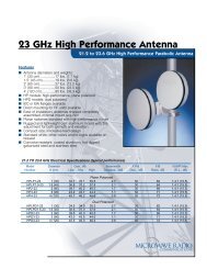
1.3.7. Remote Control Connectors (RS-485 Interface)<br />
They are located at the rear of the video unit. The connectors, in loop through<br />
configuration, are prepared <strong>for</strong> connection of the KROMA RK-5400 remote<br />
control. These connectors are also useful <strong>for</strong> to update the futures software<br />
versions.<br />
Configuration:<br />
Terminal 1 - S/C<br />
“ 2 - DATA + (RS485)<br />
“ 3 - RX (RS232)<br />
“ 4 - GND<br />
“ 5 - S/C<br />
“ 6 - TX (RS 232)<br />
“ 7 - DATA - (RS 485)<br />
“ 8 - GND<br />
REM<br />
Figure 1<br />
<strong>BM5414</strong>/20<br />
7
KROMA TELECOM<br />
PROFESSIONAL MONITORS <strong>BM5414</strong>/20<br />
2. INPUTS SELECTION<br />
2.1. CCVS KEY<br />
Key <strong>for</strong> the selection of one of the available composite inputs A , B y C.<br />
CCVS<br />
(C input is possible if the SYNC key is in the OFF mode).<br />
The first time that is pressed appears the current <strong>and</strong> in the second time<br />
will switch the input at following. The number of states will be of 2 or 3,<br />
relying on the state of the SYNC key. When this key has been pressed<br />
will appear the message:<br />
CCVS X<br />
that it will disappear lapsed a few seconds, or by mean of the ESC key.<br />
2.2. CDV KEY<br />
Key <strong>for</strong> selection of the signals applied to the vídeo digital inputs S1 <strong>and</strong><br />
CDV<br />
S2. Upon pressing this key it will appear the message: S1 or S2, it will<br />
disappear automatically a few seconds after the key-press, or when you<br />
press the ESC key.<br />
2.3. CAV KEY<br />
Similar operation to the previous cases, but <strong>for</strong> selection of inputs in<br />
CAV<br />
analog components: RGB or YPrPb.<br />
Upon pressing this key it will appear the message:<br />
RGB or YPrPb<br />
that will disappear automatically a few seconds after the key-press, or when you press<br />
the ESC key.<br />
2.4. AUX KEY<br />
Similar operation to the CCVS Key, in this case, this is the key <strong>for</strong> the<br />
AUX<br />
selection of the video signals AUX RGB <strong>and</strong> AUX DEC. When the<br />
selection is AUX RGB the signal applied to the BNC connector, in the<br />
front panel of monitor drives simultaneously to the three guns (R G B) of<br />
picture tube there<strong>for</strong>e we will see a blanck <strong>and</strong> white image.<br />
Upon pressing this key it will appear the message: AUX RGB or AUX CCVS<br />
that will disappear automatically a few seconds after the key-press, or when you press<br />
the ESC key.<br />
<strong>BM5414</strong>/20<br />
8
KROMA TELECOM<br />
PROFESSIONAL MONITORS <strong>BM5414</strong>/20<br />
3. AUXILIARY FUNCTIONS<br />
3.1. SYNC KEY<br />
Key <strong>for</strong> the selection of internal or external sync. However this function<br />
SYNC<br />
can be enabled by programming this option in sub-menu. In this case the<br />
input CCVSC will be selected with the CCVS key, as a third composite<br />
video input.<br />
After pressing this key, will appear the following messages:<br />
SYNC: INT or SYNC: EXT<br />
or<br />
SYNC-KEY OFF<br />
The message disappears automatically from the screen 4 seconds after the last keypress<br />
or when you press ESC.<br />
3.2. SIZE KEY<br />
Key to select between overscan, normal size <strong>and</strong> underscan reduced<br />
SIZE<br />
size at 95%:<br />
This selection is possible, as much being programmed the monitor<br />
with an aspect ratio 4:3 or 16:9. After to press this key, will appear<br />
the following messages:<br />
SIZE: NORM 4:3 or SIZE: U/S 4:3<br />
or<br />
SIZE: NORM 16:9 or SIZE: U/S 16:9<br />
The message disappears automatically from the screen 4 seconds<br />
after the last key-press or when you press ESC.<br />
3.3. 16:9 KEY<br />
This key allows to select the aspect ratio 4:3 or 16:9.When this key has<br />
16:9<br />
been pressed, it will appear the message:<br />
SIZE: 16: 9 SIZE: 4: 3<br />
3.4. DEL KEY<br />
Key <strong>for</strong> selection of the horizontal delay, vertical delay or both<br />
DEL<br />
("PULSE CROSS")<br />
It allows to control the presentation of sync pulses in the screen,<br />
switching between:<br />
NORMAL → H DEL → V DEL → H + V DEL<br />
In model A12<br />
<strong>BM5414</strong>/20<br />
9
KROMA TELECOM<br />
PROFESSIONAL MONITORS <strong>BM5414</strong>/20<br />
3.5. BLUE KEY<br />
It operates under BLUE ONLY function ,when the selected video input is<br />
BLUE<br />
3.6. MONO KEY<br />
composite (CCVS). By means of this function the video signal<br />
corresponding to the blue color will be applied to the three guns of the<br />
picture tube.<br />
The associated message to this key will be:<br />
BLUE ONLY ON or BLUE ONLY OFF<br />
MONO<br />
This key has 3 different states, that could switch in cyclic mode::<br />
COLOUR: MONO, AUTO or FBW<br />
Mono: In this position it is suspended the chrominance signal <strong>and</strong> presents/displays<br />
the filtered luminance.<br />
Auto: In this case, the monitor presents color images, if the signal has "BURST"<br />
FBW: Position “Full B<strong>and</strong> Width”. The monitor will present only the luminance without<br />
filter with all the complete b<strong>and</strong>.<br />
3.7. AFC KEY<br />
This key switches in cyclic mode between fast or slow time constant in<br />
the capture of synchronism H.<br />
AFC<br />
When this key has been pressed, will appear the message:<br />
AFC: FAST<br />
or AFC: SLOW<br />
3.8. DEG KEY<br />
Key to manually degauss the CRT of the monitor.<br />
DEG<br />
Indirect action by means of relay microprocessor controlled<br />
- Time of activation: 4 seconds.<br />
Minimal time <strong>for</strong> the next activation after the degaussing > 5 min.<br />
After to press this key, will appear the following messages: DEGAUSSING<br />
3.9. ESC KEY<br />
ESC<br />
This key will allow us to return to previous menu <strong>and</strong> interrupt<br />
procedures. When you return from the previous menu or shown some of<br />
the controls (BLK, CNT,...), if any parameter has been modified,it will<br />
save in static mode in the working memory.<br />
<strong>BM5414</strong>/20<br />
10
KROMA TELECOM<br />
PROFESSIONAL MONITORS <strong>BM5414</strong>/20<br />
3.10. STS (Status) KEY<br />
This key allows the programming of the internal parameters of the<br />
STS<br />
monitor through menus. In the Status menu. This key operates in<br />
recurrent mode. When pressed, are displayed the configuration<br />
parameters or return to the main menu.<br />
3.11. CHN KEY<br />
CHN<br />
It allows to change the associated audio channels to the SDI inputs,<br />
when the monitor incorporates this option with desembedded audio<br />
extractor.<br />
Pressing repeatedly it selects the 4 channels: CHN 1-2 or CHN 3-4<br />
3.12. VOL / MUTE KEY<br />
VOL<br />
MUTE<br />
When the monitor has included the Digital option with audio, once this<br />
key is pressed the audio signal is inhibited, indicating this situation by<br />
means of a symbol located on the screen bottom left h<strong>and</strong> size. The<br />
presentation of this symbol, can be deactivated in the PROG. FUNCTION<br />
menu.<br />
4. COMMAND KEYS FUNCTION<br />
4.1. BLK KEY (BLacK Level / Bright)<br />
BLK<br />
By pressing of this key from the normal mode, a message appears in<br />
the screen, indicating the current value of the black level, (Brightness)<br />
<strong>and</strong> if the value has been calibrated or not.<br />
BLACK LEVEL 00 CAL or BLACK LEVEL +10 UNCAL<br />
starting from this instant are entered in the modification mode of this value by means<br />
of the ORE 2 , increasing in the clockwise <strong>and</strong> decrease in counterclockwise.<br />
The maximum value of BLK is of +20 <strong>and</strong> the minimum is of -20.<br />
If being in this mode of work, the CAL key is pressed , the value of the black level is<br />
updated regarding the calibration value (see Appendix A), also is possible to reach<br />
the calibration value by pressing of the ORE.<br />
The exit from this mode of control of Level of Black (Brightness), to mode normal<br />
(without messages in screen) it is per<strong>for</strong>med: automatically, after 4 seconds with no<br />
press any key or manually by means of the ESC key.<br />
<strong>BM5414</strong>/20<br />
11
KROMA TELECOM<br />
PROFESSIONAL MONITORS <strong>BM5414</strong>/20<br />
4.2. CNT (CONTRAST)<br />
CNT<br />
Similar behavior to the described above, <strong>for</strong> BLCK but concerning to<br />
the gain of the final video amplifier (Contrast).<br />
The messages that could appear are:<br />
CONTRAST 00 CAL or CONTRAST -12 UNCAL<br />
4.3. SATURATION/COLOUR<br />
SAT<br />
SAT<br />
Similar behavior to the described above, <strong>for</strong> CNT but<br />
concerning to the gain of the decoder´s chrominance amplifier.<br />
This key acts on two parameters. If the input signal active is NTSC,<br />
the system internally will select the saturation of NTSC. For any another<br />
system will adjust the same parameter.<br />
SATURATION 00 CAL or SATURATION +8 UNCAL<br />
4.4. HUE/TINT (Only in NTSC)<br />
HUE<br />
Similar behavior to the described above, <strong>for</strong> CNT but concerning to<br />
the chrominance phase regarding to the burst in the decoder. Because is<br />
a parameter of the NTSC system will only be permitted their modification<br />
when the active signal corresponds to this system.<br />
The messages that could appear are:<br />
HUE 00 CAL or HUE -3 UNCAL<br />
NO AVAILABLE (if the connected signal is not NTSC)<br />
4.5. APT (APERTURE)<br />
It allows to control the transitory response of the luminance channel of<br />
APT<br />
the decoder in order to enhance, if it proceed, the "fine"details of the<br />
image, or attenuate the possible noise in this b<strong>and</strong> (2.8 Mhz/ NTSC- 4<br />
Mhz/ PAL approximately).<br />
4.6. CAL KEY<br />
Two operating modes:<br />
1. When CAL is pressed, being in one of the modes: BLCK, CNTR,<br />
CAL APT, HUE or SAT,the behavior is the described already.<br />
2. The monitor utilizes different menus on those that there is diverse<br />
active options.. with the ORE select the option <strong>and</strong> with the CAL key<br />
executes the selected option.<br />
3. In Calibración of values in set-up manual..<br />
<strong>BM5414</strong>/20<br />
12
KROMA TELECOM<br />
PROFESSIONAL MONITORS <strong>BM5414</strong>/20<br />
5. INDICATORS<br />
5.1. UNCAL LED<br />
This LED is keep activated (Red LED lit) if any of the variables:BLK, CNTR, APT,<br />
HUE or SAT, has a different value of the calibratión.<br />
In order to proceed to the calibratión of this variable, see previous paragraph, <strong>and</strong><br />
the behavior of the CAL key with the modes BLCK , CNTR, APT, HUE or SAT.<br />
6. MENU OPERATION<br />
The STS key shows the menu of STATUS through the which gives up pass to all the<br />
sub-menus, which they allow to configure all the parameters <strong>and</strong> functions from the<br />
monitor.<br />
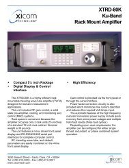
6.1. STATUS MENU<br />
When the STS key is pressed from the normal manner of operation, the following<br />
menu will appear:<br />
STATUS MENU<br />
MEM RECALL MEM STORE<br />
SET UP PROG FUNCTION<br />
PASSWORD EMBEDDED AUDIO<br />
TECH. MENU REMOTE<br />
SAFE AREA<br />
Use Wheel <strong>and</strong> CAL<br />
Figure 2<br />
The selection of the different options is carried out by means of the C.O.A.<br />
(Optical Rotary Encoder), <strong>and</strong> in order to activate the function we will press CAL.<br />
<strong>BM5414</strong>/20<br />
13
KROMA TELECOM<br />
PROFESSIONAL MONITORS <strong>BM5414</strong>/20<br />
6.2. MEMORY RECALL MENU<br />
It allows to load in the working memory. the content of whatever of the existent<br />
memories in the monitor (USER 0, USER 1, USER 2 , USER 3 or SYSTEM).<br />
MEMORY RECALL MENU<br />
USER 0 USER 2<br />
USER 1 USER 3<br />
SYSTEM<br />
Figure 3<br />
In order to select the memory that is wanted to recover one must ,press CAL in<br />
order to transfer the content as active value.<br />
6.3. SET UP MENU<br />
From this menu it could be modified <strong>and</strong> adjust the parameters of the GRAY<br />
SCALE (LL/ HL <strong>and</strong> intermediate values) <strong>and</strong> the CALIBRATION values of BLCK,<br />
CNTR, SAT, HUE, VOL <strong>and</strong> APT.<br />
When selecting this menu will appear the following sub-menu:<br />
SET UP MENU<br />
AUTO SET UP CRT/REF:<br />
MANUAL SET UP LEARN PROBE<br />
Figure 4<br />
<strong>BM5414</strong>/20<br />
14
KROMA TELECOM<br />
PROFESSIONAL MONITORS <strong>BM5414</strong>/20<br />
6.3.1. OPTION: AUTO SET UP<br />
It can be carried out, by means of the set Generator/ Analizer KROMA DG5400<br />
<strong>and</strong> probe AK4400X50 especially designed <strong>for</strong> this use.<br />
When CAL key is pressed, will appear a flashing message in the lower line,<br />
requesting the technical password. If the password is correct, the system will<br />
permit pass to one of the auxiliary inputs, (AUX RGB or AUX CCVS). In the same<br />
menu, will appear the message "SELECT INPUT: AUX CCVS however; you<br />
could select any of the available inputs by pressing the keys associated to the<br />
inputs (AUX, CCVS, CDV).<br />
SET UP MENU<br />
AUTO SET UP CRT/REF :<br />
MANUAL SET UP LEARN PROBE<br />
SELECT INPUT: AUX CCVS<br />
Figure 5<br />
In order to obtain an accurate adjustment, the monitor carries out a different<br />
adjustment <strong>for</strong> the digital inputs. For this purpose select one of the digital inputs<br />
(S1 or S2) <strong>and</strong> the system will carry out an independent adjustment of any<br />
another input. In this mode, when you change a digital input, the system will<br />
program the values of HLs <strong>and</strong> the LLs, corresponding to the digital adjustment.<br />
Consequently, will note a better response of the monitor.<br />
Independently of the type of input selected, this should coincide with the DG54xx.<br />
Once selected the inputs signal <strong>and</strong> the phosphor reference, press the key CAL<br />
in order to start the adjustment. If during any step you doubt of any parameter,<br />
you could stop the process by pressing ESC.<br />
Next appears the message: "PUT PROBE & PRESS CAL", put on the<br />
optical probe on the center of the screen <strong>and</strong> fix it to the center of the window<br />
that it will appear after a short time. Starting from this moment <strong>and</strong> during the<br />
adjustment time, don´t move the probe <strong>and</strong> not disconnect the A.S.U connector.<br />
because it will block the system owing initiate again the monitor. However, their<br />
parameters won't be affected.<br />
The adjustment is finished when appears the message: "Ok AUTO SET UP<br />
SUCCESSFULLY."<br />
<strong>BM5414</strong>/20<br />
15
KROMA TELECOM<br />
PROFESSIONAL MONITORS <strong>BM5414</strong>/20<br />
Once completed with success the adjustment, also there will be exist autocalibrated<br />
in the working memory. If you desire to keep the adjustment you could<br />
use one of the four memories (See MEMORY STORE MENU).<br />
The adjustment procedure in<strong>for</strong>ms about several events that don´t allow carry<br />
out it correctly. The messages are the following:<br />
· "CANNOT CONNECT":<br />
· "UNCOHERENT DATES":<br />
· "Not CONVERGED": it could be originated <strong>for</strong> diverse causes, the most<br />
common is the input level of the signal. Check the termination switch (HP/75 Ω).<br />
The conclusions reached are:<br />
• White D 6500 ± 200 ºK or another optional (see SEL CRT/REF)<br />
• 0.5 NIT <strong>for</strong> window signal with 10% APL<br />
• 90 NITS <strong>for</strong> window signal with 100% APL<br />
6.3.2. OPTION : CRT/REF<br />
With this option you will select a group of parameters as reference <strong>for</strong> an Auto<br />
Set Up, or to specify the group that will be modified when you select the option<br />
LEARN PROBE.<br />
With the CAL key, you will select in cyclical mode ,one of the 4 groups of<br />
parameters. Three of these are identified with the model of a C.R.T. <strong>and</strong> one of<br />
them has been reserved <strong>for</strong> the user.<br />
6.3.3. OPTION: LEARN PROBE OPTION<br />
With this option you will store some characteristics of colorimetry in the meter in<br />
order to adjust other monitors in the same conditions. For example, if the<br />
conditions of brightness of your study modify the subjective perception of the<br />
color of the monitor, or you prefer a tendency toward a determined color, then,<br />
you modify manually the characteristics of a monitor in order to take it as<br />
reference. Next, you utilize one of the four groups of parameters with the option<br />
CRT/ REF, with preference, the group of user (USER) <strong>and</strong> select the option<br />
LEARN PROBE with the key CAL.<br />
The operation of this option is similar to AUTO SET UP. You will have connected<br />
a DG5400 generator with specific patterns, in order to make the learning.<br />
Likewise ,it will request you a technical password <strong>and</strong> will also to put the<br />
measuring probe on the screen <strong>and</strong> press the CAL key in order to start the<br />
process or ESC in order to stop it. Due to the risk of data loss the operation, this<br />
should only be carried out <strong>for</strong> technical personnel. This operation is longer than<br />
the AUTO SET UP <strong>and</strong> it is essential don't move the probe during the process.<br />
<strong>BM5414</strong>/20<br />
16
KROMA TELECOM<br />
PROFESSIONAL MONITORS <strong>BM5414</strong>/20<br />
6.4. OPTION: MANUAL SET UP<br />
When you select this option MANUAL SET UP from the SET UP menu, you<br />
would be able to adjust all the values of parameters of monitor ,as much the<br />
current values as the calibration values. ie: CNT, BLK, SAT, VOL, APT <strong>and</strong> HUE;<br />
as well as the parameters LL´S <strong>and</strong> HL´S or grey scale, <strong>and</strong> the geometry.<br />
Once selected this option will request the technical password with four digits<br />
code:<br />
If correct, we will enter in the following menu:<br />
SET UP MENU<br />
Gray Scales<br />
Calibration Values<br />
Geometry Setup<br />
Cal wiht active data<br />
Figure 6<br />
6.4.1. OPTION: MENU GRAY SCALES<br />
By selecting this option,you may carry out a manually adjustment, of the<br />
current biasing levels, of the cathode of the CRT (LLs) <strong>and</strong> the gain of the<br />
RGB video amplifier, (HLs).<br />
The new menu will be the following:<br />
GRAY SCALES MENU<br />
LL R LL G LL B HL R HL G HL B - - -<br />
Figure 7<br />
<strong>BM5414</strong>/20<br />
17
KROMA TELECOM<br />
PROFESSIONAL MONITORS <strong>BM5414</strong>/20<br />
Once selected one of the options the symbols (_ _ _) located in the right<br />
h<strong>and</strong> of the lower part of the screen going to indicate the value of the state<br />
of the variable. If the CAL key is pressed again then will be stored the last<br />
current value, the dashed lines appear again <strong>and</strong> one may select another<br />
variable.<br />
By the other h<strong>and</strong>, if ESC key is also pressed, will store the modified value<br />
of the variable but it will return to the previous menu.<br />
6.4.2. OPTION: MENU CALIBRATION VALUES<br />
In this menu we could modify the associate parameters to the primary<br />
controls of the monitor.<br />
The menu from wich one we could modify the parameters is the following:<br />
GRAY SCALES MENU<br />
BLCK SAT CNTR HUE VOL APT - - -<br />
Figure 8<br />
The operation is the same as in the previous case, the dashed lines, of the<br />
right h<strong>and</strong> in lower part of screen, when pressing CAL, they will give the<br />
values of the variable. However, there are parameters with some<br />
particularities that are kept in mind:<br />
1. The Saturation (SAT): The monitor detects if you are viewing a NTSC<br />
system signal, in whose case will modify the associate parameter to this<br />
system. In any other case always modifies the other parameter. But anyway<br />
both parameters represent the saturation.<br />
2. The Volume (VOL): Although functions exist associated to the VOL key,<br />
the system of control won't give you access to this variable, except <strong>for</strong> the<br />
monitor carries incorporate the audio option.<br />
3. The Hue Option: It will only has access, if the active input signal is<br />
NTSC.<br />
4. The Aperture (APT): it will only give access to modify their value if the<br />
monitor incorporates the option.<br />
<strong>BM5414</strong>/20<br />
18
KROMA TELECOM<br />
PROFESSIONAL MONITORS <strong>BM5414</strong>/20<br />
5. Option: GEOMETRY SET UP<br />
By means of this menu could be modified the parameters in relation to the<br />
<strong>for</strong>mat of the picture, <strong>and</strong> another with more technical content. The menu<br />
through the one will be able to carry out the change is the following:<br />
GEOMETRY SET UP<br />
HEIGHT N 4:3 WIDTH N 4:3<br />
HEIGHT U/S 4:3 WIDTH U/S 4:3<br />
HEIGHT N 16:9 WIDTH N 16:9<br />
HEIGHT U/S 16:9 WIDTH U/S 16:9<br />
V. LINEARITY CORNER<br />
V- S ADJ H-COMPENSATION<br />
E-W PARAB<br />
H-PHASE<br />
V-SHIFT<br />
H-SHIFT<br />
V-COMPENSATION BEAM LIMIT<br />
TRAPEZIUM<br />
Figure 9<br />
In order to modify a parameter, this will be selected, with aid of the ORE, <strong>and</strong><br />
we pressing CAL key,then will appear in the lower line of the menu: the<br />
name <strong>and</strong> the value of the parameter, at the moment it is updated in the<br />
monitor. In the same way that in the previous menu, the operation of both<br />
keys CAL <strong>and</strong> ESC are the same.<br />
This option, provides access to the adjustment of all the variables involved<br />
with the geometry alignment of the monitor.<br />
Option: CAL WITH ACTIVE DATA<br />
With this option you will convert all the current values of the parameters, in<br />
calibration values,this option is very appropriate after carrying out an<br />
adjustment <strong>and</strong> be<strong>for</strong>e of saving the data in one of the user memories.<br />
During the process of calibration will appear in the 2 nd line of the menu,<br />
MANUAL SET UP MENU the message: "UPDATING."<br />
<strong>BM5414</strong>/20<br />
19
KROMA TELECOM<br />
PROFESSIONAL MONITORS <strong>BM5414</strong>/20<br />
6.5. OPTION: CHANGE PASSWORD MENU<br />
This new option allows us to change the access password <strong>for</strong> the several menus.<br />
Selecting “PASWORDS”, it will get the following menu:<br />
SET UP MENU<br />
USER 0<br />
USER 1<br />
USER 2<br />
USER 3U<br />
SYSTEM<br />
Figure 20<br />
Once the “USER” is selected, the menu that allows to change the technical key<br />
is:<br />
CHANGE PASSWORD MENU<br />
USER 0<br />
OLD PASSWORD : - - - -<br />
NEW PASSWORD : - - - -<br />
CONFIRM PASSWORD: - - - -<br />
Press CAL Key To Change It<br />
Figure 31<br />
When this option is selected the system presents/displays a “password<br />
menu”. where the key/code can be chosen to change individualized <strong>for</strong> each<br />
user, (By defect all the monitors leave factory with the key/code: 1111) next,<br />
it requests the new key/code of access <strong>and</strong> a confirmation of this one.<br />
In order to indicate in that phase of the process is, the four dashed lines<br />
(----) of the numerical clave code, the password will be flashing. Also, in<br />
proportion to we introduce the characters the scripts they are substituted <strong>for</strong><br />
asterisks (****).<br />
They are considered <strong>for</strong>bidden all those password that conatin the “0”.<br />
If it has been made correctly, the monitor will show the text "OK," in the last line,<br />
if not, it will show "ERROR" <strong>and</strong> it will return to the main menu.<br />
<strong>BM5414</strong>/20<br />
20
KROMA TELECOM<br />
PROFESSIONAL MONITORS <strong>BM5414</strong>/20<br />
6.6. OPTION: TECH. MENU<br />
This menu consist of options reserved to KROMA´s technicians, updatings <strong>and</strong><br />
specific operations.<br />
t<br />
TECHNICAL MENU<br />
Only Auhorized Users<br />
PASSWORD<br />
Press CAL to introduce it<br />
Figure 12<br />
6.7. Option: SAFE AREA MENU<br />
We underst<strong>and</strong> <strong>for</strong> “Safe Area” a closed frame that defines an area. The menu<br />
where you will find options in order to configure the "safe area" it is the following:<br />
SAFE AREA MENU<br />
DISABLED COLOR<br />
TOP MARGIN LEFT<br />
LEFT MARGIN RIGHT<br />
VIEW S. AREA TOP<br />
RESET S. ÁREA BOTTOM<br />
⎯⎯<br />
Figure 13<br />
Next they are detailed each one of the options of the menu.<br />
<strong>BM5414</strong>/20<br />
21
KROMA TELECOM<br />
PROFESSIONAL MONITORS <strong>BM5414</strong>/20<br />
6.7.1. Option: DISABLE<br />
In alternated mode, you could activate or disable the "Safe Area" by pressing the<br />
CAL key.<br />
There are several conditions so that don't appear the "Safe Area":<br />
1. Message "NO SYNC" active.<br />
2. Identification number of monitor activated<br />
3. Any message on the screen.<br />
4. Be modifying menus.<br />
5. Incorrect programming. Use the RESET S.A. option in order to begin the<br />
“Safe Area”.<br />
When they are activated so much the "Grid" as the "Safe Area", it will have<br />
priority the "Safe Area."<br />
6.7.2. Option: TOP MARGIN<br />
The option TOP MARGIN determines the distance between the superior margin<br />
of the image <strong>and</strong> the superior border of the frame (option: TOP). This parameter<br />
permits a more precise adjustment of the frame.<br />
With aid of the ORE select TOP MARGIN <strong>and</strong> after press CAL key, it will appear<br />
the "Safe Area" with the last established conditions. Move the ORE clockwise<br />
<strong>and</strong> couterclocwise in order to adjust the frame in the desired position. Once<br />
determined their position pulses ESC in order to validate <strong>and</strong> store returning to<br />
the SAFE AREA MENU.<br />
TOP MARGIN<br />
Figure 14<br />
<strong>BM5414</strong>/20<br />
22
KROMA TELECOM<br />
PROFESSIONAL MONITORS <strong>BM5414</strong>/20<br />
6.7.3. Option: LEFT MARGIN<br />
In the same way as the previous option, it allows to modify a parameter of fine<br />
adjustment of the "Safe Area." In this case, it is the distance between the left limit<br />
of the image <strong>and</strong> the frame.<br />
LEFT MARGIN<br />
Figure 15<br />
The procedure of adjustment is identical to the one be<strong>for</strong>e:<br />
6.7.4. Option: COLOR<br />
It is possible to modify the color of the "Safe Area" <strong>for</strong> matching the image to the<br />
background. Pressing the CAL key, we could choose one of the 8 colours.<br />
Associate to the option COLOR, on the right h<strong>and</strong> there is a window in order to<br />
see the chosen color.<br />
6.7.5. Option: VIEW S.A.<br />
It allows to make a preliminary viewing of the "Safe Area" during some seconds.<br />
Later on, go back to the menu: SAFE AREA MENU.<br />
6.7.6. Option: RESET S.A.<br />
If there is any problem with the <strong>for</strong>m of the "Safe Area" or you want to start of<br />
some well-known conditions, then you select the option <strong>and</strong> press CAL, so, you<br />
will see the "Safe Area" during some seconds <strong>and</strong> you will memorize the initial<br />
conditions. You starting from this instant could modify the parameters in order to<br />
adapt the "Safe Area" to your convenience.<br />
6.7.7. Option: LEFT<br />
By selecting this option <strong>and</strong> pressing the CAL key appears the "Safe Area," with<br />
aid of the ORE you could move to the left <strong>and</strong> to the right, the left side of the<br />
frame. When you had selected its position, press the ESC key in order to store,<br />
<strong>and</strong> return to the menu: SAFE AREA MENU.<br />
<strong>BM5414</strong>/20<br />
23
KROMA TELECOM<br />
PROFESSIONAL MONITORS <strong>BM5414</strong>/20<br />
6.7.8. Option: RIGHT<br />
With this option you could move the right side of the frame, toward left <strong>and</strong> right<br />
side.<br />
The procedure of adjustment is identical to the LEFT option.<br />
6.7.9. Option: TOP<br />
With this option you could to move the upper side of the frame towards up or<br />
down side.<br />
The procedure of adjustment is identical to the LEFT option.<br />
6.7.10. Option: BOTTOM<br />
With this option you could move the lower side of the frame towards up or down.<br />
The adjustment procedure is identical to the LEFT option.<br />
The adjustment <strong>for</strong> these last four options is showed in the following figure:<br />
⇔<br />
LEFT<br />
⇔ ⇔<br />
TOP<br />
BOTTOM<br />
RIGHT<br />
⇔<br />
Figure 16<br />
<strong>BM5414</strong>/20<br />
24
KROMA TELECOM<br />
PROFESSIONAL MONITORS <strong>BM5414</strong>/20<br />
6.8. MEMORY STORE MENU<br />
It allows to store in the working memory, with the content of any of of the existent<br />
memories in the monitor (USER 0, USER 1, USER 2, USER 3 <strong>and</strong> SYSTEM).<br />
MEMORY STORE MENU<br />
USER 0 U S E R 2<br />
USER 1 U S E R 3<br />
SYSTEM ALL<br />
Figura 17<br />
We selec the memory, the one we want to store, <strong>and</strong> we press CAL. In all the<br />
memory the technical key is asked <strong>for</strong> <strong>and</strong> while it stores the values appear message<br />
STORING in a "Flashing" way.<br />
The mode ALL will allow to store all the data in all the user memories, at one time.<br />
6.9. Option: PROG.FUNCTION<br />
In this menu some of the actions of the monitor can be configurated. The menu<br />
configuration will have the following aspect:<br />
CONFIGURATION MENU<br />
SINC KEY :<br />
CHN KEY : EMB, AUD, MENU<br />
MUTE SYM : NO ACTIVE<br />
SYNC : BLACK BURST<br />
MODE : MONITOR<br />
GRID : OFF<br />
GUN OFF SELECTION<br />
Figure 48<br />
<strong>BM5414</strong>/20<br />
25
KROMA TELECOM<br />
PROFESSIONAL MONITORS <strong>BM5414</strong>/20<br />
6.9.1. Option: SYNC KEY<br />
It allows to program the SYNC key in order to switch between internal <strong>and</strong><br />
external sync or disable it. Thereby, the INPUT <strong>and</strong> CCVS keys, could be switch<br />
to CCVSC input, making possible that the external sync input becomes an<br />
composite video input.<br />
6.9.2. Option: CHN KEY<br />
By means of this option the audio channels are configurated, when the monitor is<br />
equipped with the digital inputs module with embedded audio. By selecting the<br />
CHN KEY option it is acceded to the following menu:<br />
CHANNEL KEY CONFIGURATION MENU<br />
ACCESS EMBEDDED AUDIO MENU<br />
AUDIO OUTPUT SELECTION<br />
ANALOG AUDIO OUTPUT<br />
AES-EBU AUDIO OUTPUT<br />
Figure 59<br />
ACCESS EMBEDDED AUDIO MENU<br />
Making this selection, it is transferred to the CHN key the AES-EBU or Analog<br />
channels control by means of the optical encoder <strong>and</strong> CAL Key.<br />
AUDIO OUTPUT SELECTION<br />
With this selection CHN key changes simultaneously the ANALOG <strong>and</strong> AES EBU<br />
output channels, chosen the EMBEDDED AUDIO menu.<br />
ANALOG AUDIO OUTPUT<br />
As in the previous case, the CHN key changes in this case only the channels<br />
with ANALOG output.<br />
AES-EBU AUDIO OUTPUT<br />
Fixing this selection only the channels with AES-EBU output, pressing CHN can<br />
change.<br />
<strong>BM5414</strong>/20<br />
26
KROMA TELECOM<br />
PROFESSIONAL MONITORS <strong>BM5414</strong>/20<br />
6.9.3. Option: MUTE SYM<br />
When we select this option, the CAL key allows to activate <strong>and</strong> to disactivate the<br />
mute symbol displayed on the screen when pressing VOL/MUTE.<br />
6.9.4. Option: SYNC<br />
This option allows to select the level of external synchro. It can decide by a Black<br />
burst signal or on a st<strong>and</strong>ardized synchro signal of V pp.<br />
6.9.5. Option: MODE<br />
By means of this option the operation way can be chosen:<br />
MONITOR: Operation according to the specifications defined at the<br />
beginning of the manual.<br />
TV: In this way some of their specifications are modified adapting to the own<br />
TV receiver characteristics. In this case the chrominance signal edges are<br />
heightened <strong>and</strong> the luminance b<strong>and</strong>width is reduced to 5 MHz.<br />
6.9.6. Option: GRID<br />
This option allows to generate a chess of white squares on the picture. Their<br />
functionality is an approach in order to hide partially pictures with a reserved<br />
content .<br />
Once selected this option with the ORE, pressing CAL key, the window will be<br />
activated changing to blue color. From this point, <strong>and</strong> using again the new optical<br />
encoder, it can be chosen the three sizes of the square (2, 4, 8). Finally the<br />
function is activated with the CAL Key.<br />
As difference from other options this can not been configured as static, <strong>for</strong> this<br />
reason have to activate it every time when you switch on the monitor or after it<br />
has been deactivated by means of ESC.<br />
6.9.7. Option: GUN OFF SELECTION<br />
This option can eliminate each one of the guns from the image tube. Then, it will<br />
show following menu:<br />
GUN OFF MENU<br />
:REED : ON GREEN: ON BLUE : ON<br />
Figure 20<br />
<strong>BM5414</strong>/20<br />
27
KROMA TELECOM<br />
PROFESSIONAL MONITORS <strong>BM5414</strong>/20<br />
With the ORE the gun is selected <strong>and</strong> pressing CAL key the corresponding gun<br />
will be disactivated. Never can be suppressed more than two guns<br />
simultaneously.<br />
6.10. Option: EMBEDDED AUDIO<br />
In this menu we obtain data/in<strong>for</strong>mation relative to the audio that is inserted in the<br />
signal, in this graph we can see the number of channels occupied by group <strong>and</strong> if<br />
these are stereo or mono according to the color (Reed - stereo & Green - mono).<br />
EMBEDDED AUDIO MENU<br />
GROUP 1 2 3 4<br />
CH1 ¦ ?<br />
CH2 ¦ ?<br />
CH3 ?<br />
CH4 ?<br />
AES-EBU : OFF ANALOG: 1? 3-4<br />
Figure 21<br />
The AES-EBU & ANALOG output in the lower part, it can be selected with the slider<br />
moving the ORE. Pressing "CAL" Key we will be able to select the group <strong>and</strong> the<br />
wished channel.<br />
6.11. Option: REMOTE MENU<br />
In this menu appears two options, one of them is common to all the versions after to<br />
1.9 <strong>and</strong> the other is associated to particular software versions. The menu that goes to<br />
the control related to the remote control is the following one:<br />
REMOTE MENU<br />
REM ID 001<br />
Press CAL to change ID<br />
Figure 22<br />
<strong>BM5414</strong>/20<br />
28
KROMA TELECOM<br />
PROFESSIONAL MONITORS <strong>BM5414</strong>/20<br />
6.11.1. Option: REM ID<br />
It allows to assign to each monitor an identification number that it will be<br />
recognized <strong>for</strong> the remote control, when it is activated.<br />
By pressing the CAL key in this option, it will appear three dashed lines <strong>and</strong> the<br />
identification number of the monitor, the system wait until you introduce the three<br />
last numbers of the new identification. If you want to stop the operation, you will<br />
press the ESC key.<br />
Once carried out this operation the monitor is identified with this number, <strong>for</strong> all<br />
the remote control functions. When the remote control is activated, the monitor<br />
keeps the keyboard functions, but it has preference the remote control. (See<br />
remote control RK5400 in<strong>for</strong>mation).<br />
6.11.2. Option: REMOTE MODE<br />
This option is associated to specific "software" version. When the monitor is<br />
selected, it is converted in a remote control. If the monitor is not prepared in<br />
order to behave as remote, when you press the CAL key on this option, it won't<br />
have effect.<br />
Because of the explanation of this option it is associated to a "software" version,<br />
it will be included in a separated appendix.<br />
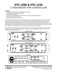
6.12. Option: CONFIG VALUES<br />
This option presents/displays on the screen the calibration parameters values.<br />
The appearance of this menu is the following one:<br />
CONFIG VALUES<br />
SYNC: INT AFC : SLOW VER : 1.9<br />
SIZE: 4:3 DEC: PAL ID: 001<br />
ACTUAL CAL ACTUAL CAL<br />
CNTR: 035 035 BCLK: 030 030<br />
SAT : 045 045 HUE : 021 021<br />
APT : --- --- VOL : --- ---<br />
HLR : 031 031 LLR : 003 003<br />
HLG : 040 040 LLG : 007 007<br />
HLB : 020 020 LLB : 004 004<br />
Figure 23<br />
This graphic in<strong>for</strong>ms to the user about the parameters values of the monitor,<br />
along with other in<strong>for</strong>mative datas.<br />
In order to have access to this menu the STS Key must be pressed twice<br />
consecutively.<br />
<strong>BM5414</strong>/20<br />
29