Powersafe VM (Warnings - Enersys - EMEA
Powersafe VM (Warnings - Enersys - EMEA
Powersafe VM (Warnings - Enersys - EMEA

You also want an ePaper? Increase the reach of your titles
YUMPU automatically turns print PDFs into web optimized ePapers that Google loves.
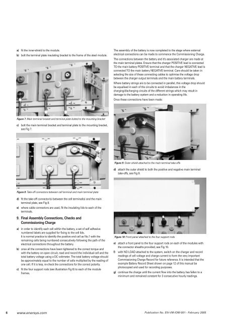
a) fit the inner-shield to the module.<br />
b) bolt the terminal plate insulating bracket to the frame of the steel module.<br />
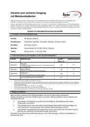
Figure 7: Main terminal bracket and terminal plate bolted to the mounting bracket<br />
c) bolt the main terminal bracket and terminal plate to the mounting bracket,<br />
see Fig 7.<br />
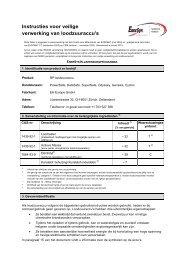
Figure 8: Take-off connectors between cell terminal and main terminal plate<br />
d) fit the take-off connector(s) between the cell terminal(s) and the main<br />
terminal plate, see Fig 8.<br />
e) where cable connectors are used, fit the insulating lids to each of the<br />
terminals.<br />
9. Final Assembly Connections, Checks and<br />
Commissioning Charge<br />
a) in order to identify each cell within the battery, a set of self adhesive<br />
numbered labels are supplied for fixing to the cell lids.<br />
It is normal practice to identify the positive end cell as No.1 with the<br />
remaining cells being numbered consecutively following the path of the<br />
electrical connections throughout the battery.<br />
b) once all the connections have been tightened to the correct torque and<br />
with the battery on open circuit, read and record the individual cell and the<br />
total battery voltage using a DC voltmeter. The total battery voltage should<br />
be approximately equal to the number of cells multiplied by the reading of<br />
one cell. If it is less, re-check the connections for the correct polarity.<br />
c) fit the four support rods (see illustration Fig 6) to each of the module<br />
frames.<br />
The assembly of the battery is now completed to the stage where external<br />
electrical connections can be made to commence the Commissioning Charge.<br />
The connections between the battery and it’s associated charger are made at<br />
the main terminal plates. Ensure that the charger POSITIVE lead is connected<br />
TO the main battery POSITIVE terminal and that the charger NEGATIVE lead is<br />
connected TO the main battery NEGATIVE terminal. Care should be taken in<br />
selecting the size of these connecting cables to optimise the voltage drop<br />
between the charger output terminals and the main battery terminals.<br />
Where battery strings are to be connected in parallel, this voltage drop should<br />
be equalised in each of the circuits to avoid imbalances in the<br />
charging/discharging circuits of the different strings which may result in<br />
damage to the battery system and a reduction in operating life.<br />
Once these connections have been made:<br />
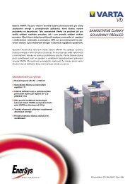
Figure 9: Outer shield attached to the main terminal take-offs<br />
d) attach the outer shield to both the positive and negative main terminal<br />
take-offs, see Fig 9.<br />
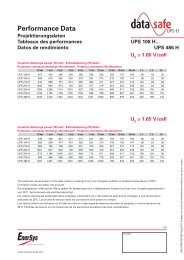
Figure 10: Front panel attached to the four support rods<br />
e) attach a front panel to the four support rods on each of the modules with<br />
the connector sheaths provided, see Fig 10.<br />
f) with NO LOAD attached to the system, switch on the charger and record<br />
readings of cell voltage and charge current to form the very important<br />
Commissioning Charge Record for future reference. It is intended that the<br />
example Battery Record Sheet shown on page 12 of this manual be<br />
photocopied and used for recording purposes.<br />
g) continue the charge until the current flow into the battery has fallen to a<br />
minimum and remained constant for 3 consecutive hourly readings.<br />
6 www.enersys.com<br />
Publication No. EN-<strong>VM</strong>-IOM-001 - February 2005