FP-4224 Flat Panel Television Stand ASSEMBLY INSTRUCTIONS
FP-4224 Flat Panel Television Stand ASSEMBLY INSTRUCTIONS
FP-4224 Flat Panel Television Stand ASSEMBLY INSTRUCTIONS

Create successful ePaper yourself
Turn your PDF publications into a flip-book with our unique Google optimized e-Paper software.
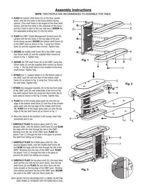
Assembly Instructions<br />
NOTE: TWO PEOPLE ARE RECOMMENDED TO ASSEMBLE THIS TABLE.<br />
A. PLACE the bottom shelf frame (C) on the floor upside<br />
down, with the five holes in the frame bottom facing<br />
upward. (This shelf frame is the largest of the three shelf<br />
frames, and has five holes in the underside of the frame<br />
and four holes in each of the rear side bars.) SCREW the<br />
five adjustable leveling feet (1) into the frame.<br />
B. PLACE the CMS ® (Cable Management System) post (D)<br />
upright with the two holes in the top edge of the post<br />
frame facing upward. SECURE the bottom shelf frame (C)<br />
to the CMS ® post as shown in Fig. 1 using four 55mm<br />
bolts (2) and the supplied Allen wrench. Tighten fully.<br />
C. SECURE the middle shelf frame (B) to the CMS ® using<br />
four 55mm bolts (2) and the supplied Allen wrench as<br />
shown in Fig. 1. Tighten fully.<br />
D. SECURE the TOP shelf frame (A) to the CMS ® using four<br />
55mm bolts (2) and the supplied Allen wrench as shown<br />
in Fig. 1. The top shelf frame is the smallest of the three<br />
shelf frames. Tighten fully.<br />
Fig. 1<br />
E. ATTACH two "L" support plates (I) to the bottom sides of<br />
the CMS ® post (D) and rear bars of the bottom shelf<br />
frame (C) as shown in Fig. 2 using four 12mm bolts (5)<br />
for each plate. Tighten fully.<br />
Fig. 2<br />
F. ATTACH two triangular brackets (H) to the top front sides<br />
of the CMS ® post (D) and undersides of the arms of the<br />
top shelf support frame (A) using four 8mm bolts (8) for<br />
each plate as shown in the Fig. 2 insets. Tighten fully.<br />
G. PLACE five of the smaller glass pads (4) onto the top<br />
edge of the bottom shelf frame (C) and five of the smaller<br />
glass pads onto the top edge of the middle shelf frame<br />
(B). PLACE five of the larger glass pads (3) onto the top<br />
edge of the top shelf frame (A) as shown in Fig. 1.<br />
H. Move the stand to the location it will occupy when fully<br />
assembled and in use.<br />
I. CAREFULLY PLACE the bottom glass shelf (F), (the<br />
deepest shelf), onto the bottom shelf frame (C) and SLIDE<br />
the edge with the hole through the slot in the CMS ® .<br />
Working from the rear of the CMS ® post, PLACE the<br />
plastic T-pin (7) through the hole in the glass to prevent<br />
the shelf from falling out of place.<br />
J. CAREFULLY PLACE the middle glass shelf (E), (the<br />
second deepest shelf), onto the middle shelf frame (B)<br />
and SLIDE the edge with the hole through the slot in the<br />
CMS ® . Working from the rear of the CMS ® post, PLACE<br />
the plastic T-pin (7) through the hole in the glass to<br />
prevent the shelf from falling out of place.<br />
K. CAREFULLY PLACE the top glass shelf (G), (the least deep<br />
shelf and the one with the two silver discs), onto the top<br />
shelf frame (A) and PLACE the two silver discs into the<br />
holes located on the top edge of the CMS ® post. Working<br />
from behind and below the top of the CMS ® post, SECURE<br />
the shelf to the CMS ® with two 35mm bolts (6).<br />
Fig. 3<br />
NOTE: ADJUST THE FIVE ADJUSTABLE FEET (1) UNDER THE BOTTOM<br />
SHELF FRAME (C) TO ENSURE THAT THE FURNITURE IS LEVEL.