MSC 79/23/Add.2 ANNEX 34 RESOLUTION MSC.192(79) (adopted ...
MSC 79/23/Add.2 ANNEX 34 RESOLUTION MSC.192(79) (adopted ...
MSC 79/23/Add.2 ANNEX 34 RESOLUTION MSC.192(79) (adopted ...

You also want an ePaper? Increase the reach of your titles
YUMPU automatically turns print PDFs into web optimized ePapers that Google loves.
<strong>MSC</strong> <strong>79</strong>/<strong>23</strong>/<strong>Add.2</strong><br />
<strong>ANNEX</strong> <strong>34</strong><br />
Page 6<br />
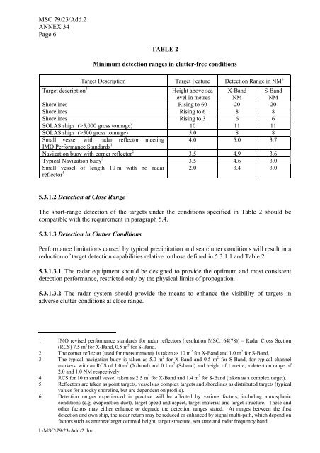
TABLE 2<br />
Minimum detection ranges in clutter-free conditions<br />
4.0 5.0 3.7<br />
Target Description Target Feature Detection Range in NM 6<br />
Target description 5<br />
Height above sea<br />
level in metres<br />
X-Band<br />
NM<br />
S-Band<br />
NM<br />
Shorelines Rising to 60 20 20<br />
Shorelines Rising to 6 8 8<br />
Shorelines Rising to 3 6 6<br />
SOLAS ships (>5,000 gross tonnage) 10 11 11<br />
SOLAS ships (>500 gross tonnage) 5.0 8 8<br />
Small vessel with radar reflector meeting<br />
IMO Performance Standards 1<br />
Navigation buoy with corner reflector 2 3.5 4.9 3.6<br />
Typical Navigation buoy 3 3.5 4.6 3.0<br />
Small vessel of length 10 m with no radar<br />
reflector 4 2.0 3.4 3.0<br />
5.3.1.2 Detection at Close Range<br />
The short-range detection of the targets under the conditions specified in Table 2 should be<br />
compatible with the requirement in paragraph 5.4.<br />
5.3.1.3 Detection in Clutter Conditions<br />
Performance limitations caused by typical precipitation and sea clutter conditions will result in a<br />
reduction of target detection capabilities relative to those defined in 5.3.1.1 and Table 2.<br />
5.3.1.3.1 The radar equipment should be designed to provide the optimum and most consistent<br />
detection performance, restricted only by the physical limits of propagation.<br />
5.3.1.3.2 The radar system should provide the means to enhance the visibility of targets in<br />
adverse clutter conditions at close range.<br />
1 IMO revised performance standards for radar reflectors (resolution <strong>MSC</strong>.164(78)) – Radar Cross Section<br />
(RCS) 7.5 m 2 for X-Band, 0.5 m 2 for S-Band.<br />
2 The corner reflector (used for measurement), is taken as 10 m 2 for X-Band and 1.0 m 2 for S-Band.<br />
3 The typical navigation buoy is taken as 5.0 m 2 for X-Band and 0.5 m 2 for S-Band; for typical channel<br />
markers, with an RCS of 1.0 m 2 (X-band) and 0.1 m 2 (S-band) and height of 1 metre, a detection range of<br />
2.0 and 1.0 NM respectively.<br />
4 RCS for 10 m small vessel taken as 2.5 m 2 for X-Band and 1.4 m 2 for S-Band (taken as a complex target).<br />
5 Reflectors are taken as point targets, vessels as complex targets and shorelines as distributed targets (typical<br />
values for a rocky shoreline, but are dependent on profile).<br />
6 Detection ranges experienced in practice will be affected by various factors, including atmospheric<br />
conditions (e.g. evaporation duct), target speed and aspect, target material and target structure. These and<br />
other factors may either enhance or degrade the detection ranges stated. At ranges between the first<br />
detection and own ship, the radar return may be reduced or enhanced by signal multi-path, which depend on<br />
factors such as antenna/target centroid height, target structure, sea state and radar frequency band.<br />
I:\<strong>MSC</strong>\<strong>79</strong>\<strong>23</strong>-Add-2.doc