JBL - The Acoustical Lens (1962).pdf
JBL - The Acoustical Lens (1962).pdf
JBL - The Acoustical Lens (1962).pdf

You also want an ePaper? Increase the reach of your titles
YUMPU automatically turns print PDFs into web optimized ePapers that Google loves.
the<br />
ACOUSTICAL LENS<br />
By GEORGE L. AUGSPURGER<br />
Operation and performance of various types<br />
of devices used professionally and in home<br />
hi-fi speaker systems to disperse and shape<br />
sound energy from horn-type driver units.<br />
PLANE LIGHT WAVES<br />
TRAVELING IN AIR<br />
AS LIGHT<br />
GOES THROUGH<br />
GLASS,<br />
VELOCITY IS<br />
DECREASED,<br />
WAVEFRONTS<br />
ARE CROWOEO<br />
CLOSER<br />
TOGETHER<br />
LIGHT EMERGES<br />
AND RESUMES<br />
NORMAL<br />
VELOCITY<br />
PORTIONS OF<br />
WAVEFRONT<br />
LEAVING CONCAVE<br />
LENS FIRST GET<br />
AHEAO OF REMAINDER.<br />
WAVEFRONT IS BENT<br />
AND LIGHT BEAM<br />
DIVERGES<br />
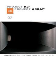
Fig. 1. Light waves passing through flat glass and concave lens.<br />
IN the last few years, more and more attention has been<br />
paid to the desirability of wide high-frequency dispersion<br />
in high-fidelity loudspeakers. This concern with a<br />
loudspeaker's distribution pattern is a good thing, but it is<br />
nothing new to the designers and users of professional equipment.<br />
In elaborate sound-reinforcement systems and theater<br />
sound installations, the problem is much more complicated<br />
than simply trying to avoid beaming of the treble frequencies.<br />
Careful control of loudspeaker directional characteristics is<br />
just as important here as are the optical properties of a spotlight<br />
to the lighting designer.<br />
One of the most sophisticated, least understood, yet certainly<br />
most interesting methods of controlling sound directionality<br />
is the employment of an acoustical lens.<br />
What the <strong>Lens</strong><br />
Does<br />
An acoustical lens is usually used in conjunction with a<br />
horn-type loudspeaker. <strong>The</strong> horn, especially in the high-frequency<br />
range, has numerous assets, but two major disadvantages:<br />
first, a good horn and driver combination tends to be<br />
more expensive than a cone-type loudspeaker and second, it<br />
is extremely directional. <strong>The</strong> first drawback is largely counterbalanced<br />
by the efficiency, dynamic range, and fidelity of the<br />
better units. <strong>The</strong> second can be overcome in a number of<br />
ways—by making the horn a special shape, by making a fanshaped<br />
array of smaller horns, or by adding an acoustical lens.<br />
<strong>The</strong> lens introduces no tonal coloration and can be designed<br />
to give almost any desired directional pattern.<br />
Historical<br />
Background<br />
<strong>The</strong> possibility of making an acoustical lens, analogous in<br />
function and operation to an optical lens, first occurred to two<br />
Bell Telephone Laboratories' engineers who were working on<br />
refraction effects in conjunction with microwave transmission.<br />
W. E. Kock and F. K. Harvey decided to see if certain techniques<br />
applicable to radio microwaves wouldn't also work, as<br />
theory suggested, with sound waves. In their experiments,<br />
they developed various acoustical converging and diverging<br />
lenses, as well as prisms.<br />
<strong>The</strong> findings of Kock and Harvey were reported in the September,<br />
1949 Journal of the ASA under the title "Refracting<br />
Sound Waves." <strong>The</strong> account is highly readable and remains<br />
the basis for present acoustical lens design.<br />
How <strong>Acoustical</strong> <strong>Lens</strong>es Work<br />
SOUNO WAVES<br />
TRAVELING<br />
THROUGH AIR<br />
ARRAY OF SMALL RIGIO ,<br />
OBSTACLES IS "INVISIBLE<br />
TO SOUNO, BUT VELOCITY<br />
IS REOUCEO<br />
SOUNO WAVES EMERGE<br />
FROM OBSTACLES<br />
AND RESUME NORMAL<br />
VELOCITY<br />
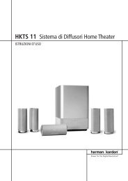
Fig. 2. Sound waves are shown passing through an obstacle array.<br />
Fig. 3. Cross-section drawing of perforated-plate acoustical lens.<br />
<strong>The</strong>re are two basic classes of acoustical lenses: the "obstacle<br />
array" and the "path-length refractor." Both operate<br />
exactly as do optical lenses, by effectively slowing down a<br />
portion of the advancing wavefront as it passes through the<br />
lens.<br />
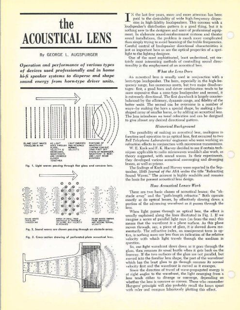
When light passes through an optical lens, the effect is<br />
usually explained along the lines illustrated in Fig. 1. If we<br />
imagine a series of parallel light rays (as from the sun) this<br />
means that the wavefront is a plane surface. As this plane<br />
moves through, say, a piece of glass, it is slowed down momentarily.<br />
<strong>The</strong> refractive index, an omnipresent term in optics,<br />
is nothing more nor less than an indication of the relative<br />
velocity with which light travels through the medium in<br />
question.<br />
So, our -light wavefront slows down as it goes through the<br />
glass, then resumes its usual bustle when it gets back on the<br />
freeway- If the two surfaces of the glass are not parallel, but<br />
curved into the familiar lens shape, the part of the wavefront<br />
which has the least glass to go through resumes its normal<br />
velocity first and the wavefront is curved as it emerges.<br />
Since the direction of travel of wave-propagated energy is<br />
at right angles to the wavefront, the light emerging from a<br />
lens tends either to diverge or converge, depending on<br />
whether the lens is concave or convex. Those who remember<br />
Huygens' principle will also probably recall the hours spent<br />
with ruler and compass laboriously plotting this effect.
To make the lens work with sound waves instead of light<br />
waves requires only that we find a substance which is transparent<br />
to sound, but which reduces the velocity of sound<br />
waves traveling through it.<br />
<strong>The</strong> Obstacle<br />
Array<br />
Harvey and Kock discovered that an array of small obstacles<br />
(small in comparison to any wavelength under consideration<br />
) has the same properties as a transparent homogeneous<br />
medium with a refractive index greater than one. In other<br />
words, sound will pass through such an array as if it wasn't<br />
there except that it comes out the other side just a little later<br />
than if it had traveled the same distance through air.<br />
Fig. 2 shows what happens. <strong>The</strong> wavefront diffracts around<br />
individual particles, but in doing so its velocity is decreased.<br />
<strong>The</strong> obstacles, it was found, could be irregular, spherical, disc<br />
shaped, or parallel strips. Even a series of perforated plates<br />
exhibited the same refractive properties, and this configuration<br />
is obviously the easiest to use in constructing a concave,<br />
diverging lens.<br />
Fig. 3 shows a cross-section of such a perforated-plate lens<br />
built into the mouth of an exponential horn. This basic design<br />
is used, for example, by James B. Lansing Sound, Inc. both in<br />
large theater assemblies and in smaller units for home highfidelity<br />
installations.<br />
Perforated-plate lenses are usually made of circular discs,<br />
and the resulting distribution pattern is symmetrical. <strong>The</strong><br />
assembly shown at (B) in the photo, for example, has a<br />
smooth distribution pattern extending through a solid angle of<br />
about 90 degrees.<br />
Path-Length<br />
Refractors<br />
This configuration is easier to understand than the obstacle<br />
array since one can see why a portion of the wavefront is delayed.<br />
In this case, the delay is achieved by making a portion<br />
of the wavefront travel a greater distance to get from one<br />
side of the lens to the other. <strong>The</strong> enforced detour produces<br />
the same results as if the sound had traveled straight through<br />
at reduced velocity.<br />
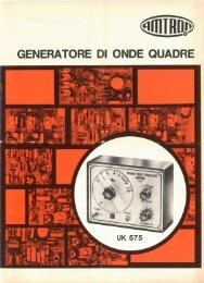
<strong>The</strong> two common varieties of path-length refractors are<br />
shown diagrammatically in Fig. 4. Sound traveling through<br />
the serpentine configuration winds back and forth until it<br />
emerges, while sound going through the slant-plate configuration<br />
travels in a straight line, except that the line is not its<br />
original direction of travel.<br />
In the latter case, common sense tells us that the emerging<br />
wavefront will be heading in a different direction than when<br />
it entered. But' common sense is wrong. Once through the<br />
detour, the sound continues in exactly the same direction as<br />
before! <strong>The</strong> separation between plates, remember, is small<br />
compared to a wavelength and the composite wavefront does<br />
not become tilted. If you are still suspicious, get out the ruler<br />
and compass and try Huygens' construction.<br />
In terms of cross-section view then, a wavefront passing<br />
through either a serpentine or a slant-plate lens emerges<br />
traveling in its original direction, having only been slowed<br />
down momentarily. Where does the lens effect take place?<br />
<strong>The</strong> answer is apparent if we look at a top view, as in Fig.<br />
5. <strong>The</strong> design shown is equally applicable to either slant-plate<br />
or serpentine lenses, and it is easy to see that from this angle<br />
at least, the device has the characteristic of a diverging lens.<br />
Such a path-length refractor can be compared to an astigmatic<br />
optical lens—it disperses sound waves in the horizontal<br />
plane while keeping them concentrated vertically. Such a<br />
distribution pattern is especially valuable in auditoriums and<br />
theaters where sound energy must be concentrated on the<br />
audience, and kept off reflecting surfaces to avoid excessive<br />
reverberation and echo.<br />
Parts (A) and (C) of the photo show two }BL driver-hornlens<br />
assemblies. <strong>The</strong> larger unit incorporates a slant-plate lens,<br />
SOUND WAVES<br />
APPROACHING<br />
PATH LENGTH<br />
REFRACTORS<br />
WAvES'TRAVELING THROUGH<br />
"DETOURS" ARE DELAYED .<br />
COMPAREO TO THOSE<br />
TRAVELING IN FREE AIR<br />
Fig. 4. Serpentine (top) and slant-plate path-length<br />
SOUNO WAVES EMERGING<br />
FROM SLANT PLATES<br />
RESUME ORIGINAL<br />
DIRECTION OF TRAVEL<br />
refractors.<br />
Fig. 5. Top view of slant-plate or serpentine acoustical lens.<br />
High-frequency reproducers using (A) serpentine-type, (Bl perforated-plate,<br />
and (CI slant-plate type acoustical lenses.
while the smaller has a serpentine lens.<br />
Like the perforated-plate lens, pathlength<br />
refractors can be designed to give<br />
almost any desired dispersion, but the<br />
ability to control horizontal and vertical<br />
distribution independently makes them<br />
even more versatile for professional use.<br />
Design<br />
Considerations<br />
Like optical lenses, acoustical lenses<br />
operate effectively only through a definite<br />
band of frequencies. <strong>The</strong> size of the<br />
horn mouth can be correlated with the<br />
characteristics of a particular lens to<br />
keep distribution uniform down to the<br />
cut-off frequency of the driver-horn combination.<br />
At the upper end of the spectrum,<br />
the smooth distribution pattern<br />
afforded by the lens begins to show<br />
irregularities as the spacing between obstacles<br />
or plates approaches a half wavelength.<br />
This means that a lens designed for<br />
use up to 10 kc. should not have the<br />
plates separated more than a half-inch or<br />
so. Horn-lens combinations have been<br />
developed which maintain uniform dispersion<br />
characteristics from 400 to more<br />
than 15,000 cps. This is an effective<br />
bandwidth of about five octaves, obviously<br />
no mean achievement.<br />
One might think that a substantial<br />
portion of the sound energy passing<br />
through a lens, especially an obstacle array,<br />
would be absorbed. As long as the<br />
lens is designed properly, and its elements<br />
are rigid, this is not the case. In a<br />
well-designed lens, less than 1% of the<br />
energy passing through the device is lost.<br />
Of course, in any type of dispersion arrangement,<br />
there is an apparent change<br />
in high-frequency intensity since all the<br />
energy which was formerly concentrated<br />
in a narrow beam is now spread through<br />
a much greater angle.<br />
If one wants to pursue the optical<br />
analogy far enough, focal lengths and<br />
even f numbers can be assigned to acoustical<br />
lenses. <strong>The</strong> unit shown in part (B)<br />
of the photo, for example, is roughly<br />
equivalent to a 150 mm. f/0.5 optical<br />
lens. It will probably be some time before<br />
a comparable unit is available to<br />
camera enthusiasts.<br />
A<br />
Reprinted From Electronics World, December, <strong>1962</strong><br />
Copyright ft 1062 by Ziff-Davis Publishing Company. All rights reserved.<br />
REPRINTED FROM<br />
Electronics World<br />
THE MAGAZINE FOR THE ELECTRONICS PROFESSIONAL<br />
PRINTED IN US A.