Audiomods tonearm kit build
Audiomods tonearm kit build
Audiomods tonearm kit build

Create successful ePaper yourself
Turn your PDF publications into a flip-book with our unique Google optimized e-Paper software.
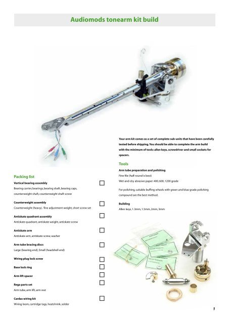
<strong>Audiomods</strong> <strong>tonearm</strong> <strong>kit</strong> <strong>build</strong><br />
Your arm <strong>kit</strong> comes as a set of complete sub-units that have been carefully<br />
tested before shipping. You should be able to complete the arm <strong>build</strong><br />
with the minimum of tools: allen keys, screwdriver and small sockets for<br />
spacers.<br />
Tools<br />
Packing list<br />
Vertical bearing assembly<br />
Bearing carrier, bearings, bearing shaft, bearing caps,<br />
counterweight shaft, counterweight shaft screw<br />
Counterweight assembly<br />
Counterweight (heavy), `fine adjustment weight, short screw set<br />
Antiskate quadrant assembly<br />
Antiskate quadrant, antiskate weight, antiskate screw<br />
Antiskate arm<br />
Antiskate arm, antiskate screw, washer<br />
Arm tube preparation and polishing<br />
Fine file (half-round is best)<br />
Wet-and-dry abrasive paper: 400, 600, 1200 grade<br />
For polishing, suitable buffing wheels with green and blue grade polishing<br />
compound are the best method.<br />
Building<br />
Allen keys, 1.3mm, 1.5mm, 2mm, 3mm<br />
Flat instrument screwdriver<br />
7/32” or 5.5mm socket for bearing nuts<br />
Small sockets or tubes for ues as spacers<br />
Arm tube bracing discs<br />
Large (bearing end), Small (headshell end)<br />
Wiring plug lock screw<br />
Base lock ring<br />
Arm lift spacer<br />
Rega parts set<br />
Arm tube, arm lift, arm rest<br />
Cardas wiring <strong>kit</strong><br />
Wiring loom, cartridge tags, heatshrink, solder<br />
1
<strong>Audiomods</strong> <strong>tonearm</strong> <strong>kit</strong> <strong>build</strong><br />
Modify the arm tube<br />
Preparing the armtube is the most time-consuming part of the <strong>build</strong>.<br />
Polishing the arm tube<br />
There is no sonic advantage in polishing the arm tube. It just looks nice. The<br />
other modifications to the arm tube are what affects the performance. Unless<br />
you have access to some simple power tools, polishing is a long job!<br />
To polish the arm tube:<br />
- First file off any casting marks, particularly around the headshell and the<br />
bearing journal<br />
- If possible, use an old counterweight stub and chuck the arm tube in lathe.,<br />
supporting the headshell end with a suitable rod through the wiring hole, held<br />
in the tailstock (essential). You can then turn the arm tube around to work on<br />
the casting marks and then spin it to smooth the tube.<br />
Without the help of a lathe, it is best to hold the arm tube very lightly in a vice.<br />
Use rubber jaws or wrap the arm tube to protect it.<br />
- Use 320 through 1200 grade papers to smooth off the armtube<br />
- Polish using medium and fine buffing wheels/compounds in a bench grinder<br />
(best) or a power drill. It is possible to use a dremel-type tool, but it will be a<br />
slow job!.<br />
Drilling an arm tube<br />
The hole pattern is important because it is the one that reduces the siffness of<br />
the tube least. The hole pattern has been carefully refined for the most effect<br />
and the holes:<br />
– reduce the arm tube mass without affecting the stiffness, letting it store less<br />
energy.<br />
– allow the arm tube to expand a little when the internal bracing disc are<br />
inserted. These put the whole arm under tension and are very important for<br />
controlling the bass resonse – more than 30dB down over the RB1000 in the<br />
low bass.<br />
– help control standing waves at high frequency by breaking up the path along<br />
the surface.<br />
– Overcome an issue where the primary mode of the air volume inside the arm<br />
is very close to the basic frequency of the arm tube.<br />
See the drilling guide and drilling template included<br />
with your <strong>kit</strong> for detailled instructions.<br />
Cut along here<br />
A<br />
Join A-A<br />
Bearing end<br />
Headshell end<br />
A<br />
AudioMods<br />
5 Tormore Mews, Rectory Road, Deal, Kent CT14 9SX, England<br />
Tel: +44 (0)1304 379698<br />
www.audiomods.co.uk<br />
Drill Template<br />
Starting at the bearing end use these drills:<br />
3.5mm, 3mm, 2.5mm, 2mm<br />
Depending on the exact position of the template around the tube,<br />
six holes of each size should work. Check before you drill and mark<br />
the holes to show where to change drill size<br />
For the small holes: 2mm, 1.5mm, 10-12 of each.<br />
2
<strong>Audiomods</strong> <strong>tonearm</strong> <strong>kit</strong> <strong>build</strong><br />
Arm cross bracing<br />
This is a very effective way of controlling resonances in the arm tube and it is<br />
critical for the low-frequency performance of the arm.<br />
Aluminium discs are fitted into the arm tube approximately 1/3 and 2/3 along.<br />
They need to be of a very precise diameter to fit properly. When we supply<br />
the arm tube, these disks are included. Because arm tube castings vary, it’s not<br />
possible to provide discs of the right size to fit existing arms. The headshell end<br />
will be between 10.25 and 10.83mm and the bearing end 10.35 and 10.875mm.<br />
Press-fit the discs into the arm tube using a<br />
threaded rod and nuts as shown below<br />
Use a 4mm threaded rod and two locked nuts to fit the discs into the tube.<br />
Once the first (smallest disc is in roughly the right place, hold the arm tube in<br />
one hand and tap the end of the fitting rod with a small hammer to firmly fix<br />
the disc in place. Repeat with the second disc. The discs should be fitted quite<br />
firmly so that they are an “interference fit” to strengthen up the whole arm tube.<br />
The discs are supplied separately marked “Small” and “Large”. If you should mix<br />
them up, the large one can be identified by a punched dot.<br />
Essential armtube mods<br />
Whatever other changes you make, these two easy modifications need to be<br />
done. These modifications will already be done if we supply the arm tube.<br />
Earth the armtube<br />
The arm is originally earthed by a strap fixed into the counterweight thread.<br />
This can cause problems even on standard arms.<br />
If you are using our upgrade <strong>kit</strong> then the armtube must be earthed – ceramic<br />
bearings won’t conduct! Drill a 1mm hole in the underside of the armtube<br />
about 20mm from the pivot centre. Check first that it misses the arm lift. Take<br />
a small piece of 1mm copper wire (a bit of coax cable core or 5A mains cable<br />
is ideal). Hold a suitable bit of steel rod etc. horizontally in your vice as an anvil<br />
and slide the armtube over it. Tap the copper wire to lock it into the drilled hole<br />
like a tiny rivet.<br />
Drill a 2mm (not critical) hole near to your copper earth stud. The earth wire<br />
comes out here and solders onto the stud.<br />
Hole for ground wire to exit<br />
Either drill hole for a copper tag to<br />
solder to or drill/tap for an M2 screw<br />
Alternatively, if you have the right tools the best method is to tap and<br />
countersink an M2 thread and use a screw to fix the ground wire.<br />
Elongate the wiring hole<br />
The hole underneath the armtube where the wire exits needs to be made oval<br />
so that the wires can still exit once the bearing carrier is installed.<br />
Elongate the hole by about 5-10mm towards the headshell. A small round file<br />
is ideal for this. The picture shows the two holes under the armtube needed for<br />
the grounding wire.<br />
3
<strong>Audiomods</strong> <strong>tonearm</strong> <strong>kit</strong> <strong>build</strong><br />
Building up the arm<br />
Once you are satisfied with your armtube, it is time to <strong>build</strong> the arm.<br />
Clean out the bearing journal. This should need very little work but there may<br />
be rough edges. 600 grade abrasive paper is normally all that is needed.<br />
If there are any small bumps or pips, smooth them with a fine file. The bearing<br />
carrier is a very precise fit, so it is important that there are no high spots in the<br />
arm tube.<br />
Don’t make the hole any larger!<br />
Install the bearing carrier.<br />
NOTE: treat the end faces of the small diameter of the bearing carrier with great<br />
care. This is the face the bearings seat on and is easily damaged, so don’t press<br />
on them.<br />
You will need a small vice or a clamp wide enough to hold the armtube and the<br />
carrier, together with spacers.<br />
• Remove the steel shaft from the bearing carrier before pressing the carrier<br />
into the arm. The shaft might be quite tight, but it does push out!<br />
• Select two suitable spacers. Small (1/4” drive) sockets are ideal for this. One<br />
should fit over the small diameter of the carrier and rest on the shoulder. An<br />
8mm socket should suit. The other should be large enough to allow the carrier<br />
to pass through but be small enough to rest on the rim of the armtube. Try<br />
13mm size.<br />
There is a small punched mark on the top of the carrier which should align with<br />
the top of the armtube. Rega armtubes have a locating tab on the top of the<br />
bearing journal to help you.<br />
• Using your spacers, gently press the carrier into the arm tube. Stop when it is a<br />
few millimetres in to check that it is aligned properly with the armtube.<br />
The bearing carrier has a very slight taper, so the first millimetre or two should<br />
go in with moderate pressure. If it doesn’t the armtube needs cleaning out.<br />
If you offer the counterweight stub screw up, it should make a straight line<br />
down the tube. At this point, you can twist the carrier a little if needed. Once<br />
you are sure that it’s correctly aligned, press the tube home until it is centred in<br />
the arm.<br />
Quite a lot of pressure is needed to completely install the carrier. This is normal,<br />
it is meant to be an interference fit so that the whole assembly behaves like one<br />
piece when finished.<br />
- Now trial-fit the counterweight stub to check for fit. You may need to press<br />
the carrier very slightly in one direction or the other to centre it. If the carrier<br />
is twisted in the arm tube don’t attempt to turn it! It is possible to simply press<br />
the carrier almost right out, adjust it and press it back again.<br />
When you are happy with the fit of the carrier, fit the steel bearing shaft, the<br />
bearings and the end caps. You need to remove the counterweight stub before<br />
installing the bearing shaft. The tightness of the nuts is not critical, but they can<br />
be quite tight to soidly fix the bearings.<br />
• With the armtube horizontal, the right way up and with the headshell towards<br />
the left, check that you have the bearing carrier the right way round. The easiest<br />
way to make sure is to check with the counterweight stub screw. When the<br />
screw aligns with the armtube, that’s correct.<br />
Fitting the counterweight stub<br />
The counterweight stub bolts onto the thread in the bearing carrier. Armtubes<br />
have varied a little over the years so, to get a perfectly aligned fit, you may need<br />
to shorten the screw a little. The stub can move sideways a little to centre it on<br />
the arm tube.<br />
Use one spacer that fits on the shoulder of the bearing<br />
carrier and a second one that rests on the arm tube but is<br />
large enough to let the carrier fit inside<br />
4
<strong>Audiomods</strong> <strong>tonearm</strong> <strong>kit</strong> <strong>build</strong><br />
Fit the arm lift and arm rest<br />
Before mounting the arm tube it’s best to fit the arm lift and arm rest. A spacing<br />
collar is supplied for the arm lift which fits onto the arm lift and sits underneath<br />
the arm lift plate.<br />
To fit the arm lift: remove the plastic quadrant (1.3mm hex key). Undo the top<br />
cap of the arm lift (careful, there is a small spring inside!). Add the spacer and<br />
fit the arm lift to the plate. To avoid scratching the arm lift plate, it’s best to hold<br />
the arm lift cap still and rotate the body of the arm lift until it’s tight in the right<br />
position.<br />
The bearing caps are not interchangeable so be sure not to mix them up. Mark<br />
the arm yoke and one arm cap with a small piece of tape before removing the<br />
caps.<br />
You can identify the outside/inside edge of the caps because only the outside<br />
is polished.<br />
Mounting the arm tube<br />
Remove the bearing caps<br />
Place the armtube complete with its bearings on the arm yoke<br />
Add the caps and screws, but don’t tighten. The antiskate quadrant locates<br />
under the back left-hand screw.<br />
Gently move the armtube until it is centred across the yoke.<br />
Tighten the caps until finger pressure doesn’t move the armtube in the yoke.<br />
You shouldn’t need to apply more pressure than you can with the short end of<br />
your allen key.<br />
The armtube can be taken off the yoke again when you wire the arm.<br />
NOTE: Whilst you can fit/remove the vertical bearings (the ones in the arm<br />
yoke) the horizontal bearings in the base are set up before leaving us. Don’t<br />
move the screws in the bearing carrier or the three grub screws in the ring<br />
holding the top plate as these are part of the bearing adjustment.<br />
AudioMods<br />
5 Tormore Mews, Rectory Road, Deal, Kent CT14 9SX, UK<br />
Tel: +44 (0)1304 379698<br />
www.audiomods.co.uk<br />
5
<strong>Audiomods</strong> <strong>tonearm</strong> <strong>kit</strong> <strong>build</strong><br />
Mounting, wiring and setting up the arm<br />
The arm needs to be mounted at the correct distance from the turntable<br />
spindle.<br />
If you already have a turntable with the armboard set up for a Rega arm, the<br />
existing mounting should be correct and the arm will be a simple drop-in<br />
replacement. If you are mounting a Rega-geometry arm for the first time, you<br />
can download a mounting template here:<br />
Five-pin <strong>tonearm</strong> connection - male plug in base<br />
View of pins from base of <strong>tonearm</strong><br />
Arm ground<br />
Right –V<br />
Left –V<br />
Right +V<br />
Right +V<br />
http://www.audiomods.co.uk/mountingTemplate.pdf<br />
Wiring the arm<br />
One-piece looms<br />
If you decide to use a single <strong>tonearm</strong> wire/interconnect loom of the Incognito<br />
type then follow the manufacturer’s instructions and wire the arm from the<br />
base up. You will still need to run a separate ground wire from the arm tube as<br />
described above because the ceramic bearings don’t conduct and isolate the<br />
arm tube.<br />
You can adopt a slightly different technique which makes the wiring easier than<br />
with a Regular arm.: Take off the arm tube and fit guide wires for signal and<br />
ground wires to it. Feed the wires up through the base and install the base plug.<br />
Now solder the wires to your arm tube guide wire and lower the arm onto the<br />
yoke as you pull the wires through. Finish by adding the cartridge tags.<br />
Typical cartridge pin connections<br />
(some are reversed top/botom)<br />
Left –V<br />
(blue)<br />
Left +V<br />
(white)<br />
Right +V<br />
(red)<br />
Right –V<br />
(green)<br />
For the five-pin plug, follow the same procedure as the complete loom.<br />
NOTE: For the very best hum suppression, the wire within the armtube could<br />
be twisted into pos/neg pairs. Bind each end of the twist run to stop it coming<br />
undone. Also twist in the direction that will tighten, not undo, Litz wires! This is<br />
probably well worth doing for very low-output cartridges.<br />
Soldering cartridge tags<br />
The best way to deal with cartridge tags is to mount the tag onto a cocktail<br />
stick held to the bench with blu-tac. Tin the cartridge tag and the wire first, then<br />
heat the tag and apply the wire.<br />
Always check each wire with a multimeter first and remember to put the<br />
heatshrink onto the wire before soldering the tag on.<br />
NOTE: When you test the grounding for continuity you will find that the base,<br />
arm lift plate and arm tube are grounded. The arm yoke will not be grounded.<br />
This is correct.<br />
AudioMods<br />
5 Tormore Mews, Rectory Road, Deal, Kent CT14 9SX, UK<br />
Tel: +44 (0)1304 379698<br />
www.audiomods.co.uk<br />
6
<strong>Audiomods</strong> <strong>tonearm</strong> <strong>kit</strong> <strong>build</strong><br />
Mounting the cartridge<br />
Follow the instructions that came with your cartridge for suitable mounting<br />
screws etc. The headshell takes the standard 12.7mm (1/2 inch) mounting with<br />
screws of M2.5 size. Some cartridges may be sensitive to the tightness of the<br />
mounting screws.<br />
222.25 mounting centres<br />
66/121null points<br />
239.5mm effective length<br />
17.25mm overhang<br />
23° offset<br />
Treat the signal wires carefully, they are easily damaged. Hold the cartridge tag<br />
lightly with tweezers by the coloured insulation. NEVER pull the tag by the wire.<br />
The cartridge tags should slide easily onto the contact pins and make a firm<br />
contact. A few cartridges use pins of smaller diameter than normal and in<br />
that case it might be necessary to squeeze the contacts of the tags<br />
together slightly before fitting them to the cartridge.<br />
If you are replacing an arm with Rega geometry then the mounting<br />
distance should already be correct and you only need to set up<br />
the cartridge.<br />
If you have an old cartridge, use it for a first setup and test. Cartridges are<br />
expensive and very easily damaged!<br />
Pivoted arms don’t hold a cartridge tangentially to the record. By setting up the<br />
arm to a calculated set of measurements we can reduce the geometrical errors<br />
to a minimum to extract the best performance. Accurate setup will make a very<br />
big difference to the results from your turntable.<br />
The measurements we want are:<br />
Arm Mounting (pivot to spindle) distance: 222mm<br />
Stylus to arm pivot point (the “effective length”): 239mm<br />
And the following settings which it is not normally necessary to measure.<br />
They should be right when the setup is complete:<br />
Overhang: 17.25mm When the arm is over the record spindle, this is the<br />
distance from the spindle centre to the stylus tip.<br />
Our setup procedure is based on measurements by BV Pisha and MD<br />
Kessler and will produce very reliable results. Using the two-point setup<br />
gauge compensates for small errors in mounting and effective length<br />
but there are many setup systems available that can offer high-precision<br />
alignment to achieve the ultimate performance.<br />
If you are happy with the technicalities of <strong>tonearm</strong> setup, you may choose<br />
to use different settings. For example, very good results can be had from<br />
Stevenson Geometry.<br />
Spindle<br />
Mount the protractor on the turntable<br />
spindle on top of a scrap record<br />
Set the stylus on each of these two points in turn<br />
and align the cartridge square to the guide lines<br />
AudioMods<br />
www.audiomods.co.uk<br />
5 Tormore Mews, Rectory Road, Deal, Kent CT14 9SX, England<br />
Tel: +44 (0)1304 379698<br />
Cartridge offset angle: 23° The angle of the cartridge in the headshell.<br />
If you can’t achieve the exact mounting distance, don’t despair! There is a good<br />
range of adjustment available in the headshell and it can accommodate a<br />
variation of a couple of mm. If you can get the cartridge properly square at the<br />
two null points, the setup isn’t far wrong!<br />
Cartridge setup<br />
1 Mount the cartridge. It should look nicely square in the headshell and the<br />
stylus tip should be vertically below the front end of the headshell as a starting<br />
point<br />
2 Set a light tracking force to stabilise the arm when the cartridge is resting on<br />
the gauge. Adjust the VTA to an approximate setting.<br />
3 Test the cartridge setup using the 66/221 null template on top of a scrap<br />
record. Rotate the platter so that the stylus can be lowered onto each null<br />
point in turn. (Don’t move the platter with the stylus touching the paper) The<br />
cartridge should be dead square when the stylus is on each null point.<br />
7
<strong>Audiomods</strong> <strong>tonearm</strong> <strong>kit</strong> <strong>build</strong><br />
Cartridge vertical (azimuth) alignment.<br />
The cartridge should be aligned so that the stylus is vertical in the groove<br />
looking from the front. You can check this either by aligning the body against<br />
the gauge supplied or using a small piece of mirror under it.<br />
Cartridge mounting surfaces – especially plastic or wooden ones – sometimes<br />
aren’t perfect and generators and cantilevers aren’t always perfectly aligned<br />
within the cartridge body, so using a mirror to set up to the cantilever, rather<br />
than the cartridge body, is the best method. Adjust the setting with tiny paper<br />
slips under one mounting screw.<br />
VTA adjustment<br />
Though normally referred to as “vertical tracking angle” what we really want<br />
to be correct is the “stylus rake angle”, or when the diamond is vertical in the<br />
groove. To make sure you are setting this correctly, set the tracking force<br />
first, adjust the VTA, then re-check the tracking force. You should make a final<br />
adjustment to the VTA by listening tests, but the best starting point and in<br />
most cases the correct setting, is when the top of the cartridge is parallel to the<br />
record surface.<br />
Non-micrometer arms:<br />
Loosen the VTA lock in the base and slide the arm up/down to get the required<br />
height. Gently tighten the screw.<br />
If you find that you are playing the arm raised by more than 5-6mm it would<br />
be best to add a spacer beneath the base. We can supply spacers to match the<br />
base of both arm types or custom mounting plates to match your turntable.<br />
There should be plenty of vertical adjustment to get the cartridge aligned.<br />
Depending on your cartridge, it should be set up correctly when either the<br />
front face is vertical or the underside of the headshell is parallel to a scrap<br />
record. Both tone and stereo imaging are affected by the VTA setting. Record<br />
thicknesses vary and the cutting angle changed from label to label, lathe to<br />
weight. The mass you want to achieve is determined by the compliance of<br />
your cartridge. There are a number of online calculators that will give you the<br />
right figure if you input your cartridge compliance and the desired resonant<br />
frequency (usually about 10Hz). A resonant frequency of between 9 and 12Hz<br />
should work in almost all applications.<br />
The bare <strong>Audiomods</strong> arm will have an effectve mass of between 9 and 11<br />
grams, depending on which counterweight you are using and its position<br />
on the stub. The effective mass goes up as the counterweight moves back. A<br />
difference of 1-2g in the total effective mass will have very little effect on the<br />
resonant frequency.<br />
A good indicator of when extra mass is needed is the bass performance. If bass<br />
seems light, you may need to add one of the optional headshell shims.<br />
With most cartridges you will achieve a correct effective mass without any<br />
adjustment because cartridge bodies tend to be heavier as the compliance<br />
goes down, so a high-compliance Grado at 6g and a medium-compliance<br />
Ortofon with a 10g body can both be fitted without any adjustment.<br />
Headshell shims<br />
A set of headshell shims is is an option with the Classic arm to add mass when<br />
using cartridges of low compliance. These fit between cartridge and headshell.<br />
To make a small adjustment for cartridges such as the Lyra Argo, add one of<br />
the aluminium shims. Moving coil cartridges with a light body like the ZYX, or<br />
ones where the maker’s advice is for a medium to high mass arm, eg Benz, will<br />
benefit from the thinner Adjust copper the vta shim. so that For the more underside extreme of the examples headshell (standardbodied<br />
Denon 103, Shelter etc) the heavy shim may work best. You should not<br />
rests flat on the cylinder<br />
need the shims for moving magnet cartridges.<br />
17mm<br />
lathe, so it may never be perfect. You can do a final fine adjustment by ear.<br />
Tracking weight (VTF)<br />
Use stylus scales to set the tracking weight. Digital scales (jeweller’s scales) are<br />
the best choice. You should always aim to measure the VTF with the stylus at<br />
the same height as when it is playing a record. The safest starting point is to set<br />
VTF at the manufacturer’s highest setting. Records are many times more likely<br />
to be damaged by too low rather than too high a force. For critical setups, the<br />
VTF can be reduced by 5-10% in very warm conditions.<br />
To move the counterweight, loosen the inset nylon lock screw with a small, flat<br />
blade screwdriver. Roughly set the tracking force with the main weight, lightly<br />
tighten the lock screw, then adjust to the final setting by rotating the small fine<br />
adjustment weight.<br />
Mass loading<br />
You should match the effective mass of the arm to the cartridge that you are<br />
using. This is calculated as bare arm effective mass + cartridge and fixing screw<br />
Use a scrap record to get the<br />
correct setting<br />
Setting the arm height - micrometer arms<br />
A vta setting gauge is supplied with theoptional micrometer arms to<br />
help with the initial setup.<br />
The white plastic cylinder is 17mm high, a common measurement for many<br />
cartridges so, before you mount a cartridge, place vta cylinder on top of a<br />
scrap record and adjust the arm vta so that the underside of the headshell<br />
rests flat on the top of the cylinder. Make a note of the micrometer setting<br />
and it will give you accurate alignment with the headshell parallel for a<br />
cartridge 17mm high.<br />
If you are using a cartridge of different height or using headshell shims, add<br />
or take off the difference on the micrometer, it is 0.5mm per complete turn.<br />
Once the cartridge is mounted, you can do the final adjustment by ear, but<br />
you will have a reference setting to come back to.<br />
8
<strong>Audiomods</strong> <strong>tonearm</strong> <strong>kit</strong> <strong>build</strong><br />
Twist clockwise to<br />
increase force<br />
Twist anticlockwise<br />
to decrease force<br />
Fit to outer hole for<br />
high force range<br />
Fit to inner hole for<br />
low force range<br />
Setting antiskate<br />
Set the thread to run in the<br />
groove in the quadrant<br />
The amount of antiskating force we need to apply<br />
is affected by many things: groove friction, tracking<br />
error, groove modulation, stylus profile etc.<br />
So we have a force constantly varying as the record is<br />
played that we must counteract without knowing its exact value. Setting up<br />
on a blank disc is not accurate because it doesn’t reflect the real drag value of<br />
the cartridge in the groove or an average value of the dynamic drag. Setting<br />
up with a test record is better but here it’s important to set up at a number<br />
of points across the record. Avoid the highly modulated grooves of test<br />
records, these will return an antiskate value far higher than most music. Careful<br />
Arm Centre point<br />
listening with known records is the best test. Listen carefully at outer and inner<br />
grooves, around the null points and halfway between them. Distortion from<br />
bias setup can be identified because it appears on one channel: right channel,<br />
underbiased, left channel, overbiased. A slight mismatch might be heard by the<br />
stereo image moving to left (under) or right (over).<br />
Our quadrant antiskate does help you to optimise the force across the record,<br />
weighting it at the outer and/or inner grooves. The setting arrived at will be<br />
influenced by your cartridge and the kind of music you play.<br />
Depending upon the stylus profile, simple acoustic music will probably be<br />
more neutrally biased, whilst orchestral or opera that tends towards crescendo<br />
on the inner grooves might need a bias weighted towards the record’s centre.<br />
A high-compliance cartridge might need a bias slightly weighted towards the<br />
outer grooves. Only listening will tell.<br />
Turn the antiskate arm to a<br />
position where the thread sits in<br />
the groove of the quadrant.<br />
Adjust the height of the weight<br />
by sliding the lead disc up or<br />
down the thread.<br />
Centre point<br />
Setting up the antiskate weight<br />
The weight and quadrant are supplied separately together with the quadrant<br />
mounting screw. Add the quadrant and hook the thread through the eye of the<br />
antiskate arm. Turn the antiskate arm so that the thread sits in the groove of the<br />
quadrant. If the antiskate weight appears too high or low the position can be<br />
adjusted by sliding the little lead disk inside it up or down the thread.<br />
There are two mounting holes for the antiskate quadrant which allows a choice<br />
of ranges of force. As a general rule, choose the outer one for low-compliance<br />
cartridges and the inner one for high compliance ones.<br />
The best starting point for fine-tuning the antiskate is to set the<br />
quadrant centred on the centre point of the arm tube. To increase<br />
the force, rotate it clockwise, rotate anticlockwise to decrease it.<br />
AudioMods<br />
5 Tormore Mews, Rectory Road, Deal, Kent CT14 9SX, England<br />
Tel: +44 (0)1304 379698<br />
www.audiomods.co.uk<br />
9
<strong>Audiomods</strong> <strong>tonearm</strong> <strong>kit</strong> <strong>build</strong><br />
Matching the counterweight to your arm<br />
NOTE:<br />
Undo the three screws to dismantle the weight<br />
Depending on the cartridge(s) you are using, your counterweight may<br />
have been delivered with one or more of the lead infill discs already<br />
removed and supplied separately, along with alternative long and short<br />
screws.<br />
Follow these instructions in reverse to add extra disks if necessary.<br />
The <strong>kit</strong> is supplied with the heavy version of the counterweight, which has<br />
four lead fill disks and should balance cartridges of 8g or more. It is normally<br />
shipped with two disks fitted and two supplied separately, together with<br />
extra long and short screws. For extra heavy or light cartridges you can add or<br />
remove one or more of the discs to match up your arm.<br />
Changing the cartridge mass<br />
• Remove the counterweight from the arm.<br />
• Undo the three screws holding the counterweight together.<br />
• If you lightly tap the weight on your work surface one of the end plates should<br />
separate from the lead fill discs.<br />
Each disc has a punch mark on it to show the alignment for re-assembly.<br />
To remove a disc use a very sharp, fine blade like a scalpel or an instrument<br />
screwdriverto separate a disk. Do this from the centre or from the screw holes<br />
to avoid marking the outside of the discs.<br />
The two plates and<br />
the lead must be<br />
re-assembled with<br />
exactly the same<br />
alignment<br />
Re-assemble the counterweight, making sure that the lead disks are in the same<br />
position as before. Only fit the screws very loosly so that all the parts can move<br />
a little. Don’t tighten them.For one disc, use the shortest screw, 2-3 medium<br />
screws, all 4, the long screws. Slide the counterweight over the stub and tighten<br />
the screws. If the weight doesn’t line up properly then the disc is rotated or<br />
flipped out of its original position.<br />
Keep the spare discs carefully and they can be added again if needed.<br />
Locking screw hole<br />
The lead disc is marked to show<br />
the position. Replace it with the<br />
mark aligned with the locking<br />
screw.<br />
AudioMods<br />
5 Tormore Mews, Rectory Road, Deal, Kent CT14 9SX, UK<br />
Tel: +44 (0)1304 379698<br />
www.audiomods.co.uk<br />
10
<strong>Audiomods</strong> <strong>tonearm</strong> <strong>kit</strong> <strong>build</strong><br />
Dimensions<br />
Counterweight shaft<br />
12mm dia x 32mm<br />
Counterweight 35mm dia<br />
nominal vta extension 2mm<br />
Base 31 dia x 13mm<br />
Fine adjustment<br />
weight spindle<br />
24mm<br />
Minimum armboard thickness 6mm<br />
Lock nut 32mm dia x 6mm<br />
41mm<br />
Outer base threaded M23x1<br />
Minimum clearance for wiring 15mm<br />
ITEM Arm dimensions - reference only<br />
Arm mounting template<br />
MATERIAL<br />
FINISH<br />
TOLERANCES See parts drawings<br />
SCALE 1:1<br />
Jeff Spall<br />
5 Tormore Mews, Rectory Road, Deal, Kent CT14 9SX<br />
jeff@audiomods.co.uk<br />
Effective length<br />
239.5mm<br />
Armboard to headshell<br />
45mm<br />
Mounting hole<br />
Clearance size for 23mm<br />
Tolerance 23.25 - 24.5mm<br />
(23.1mm in metal arm boards)<br />
Centres 222.25mm<br />
V1.2 30/12/2013<br />
Spindle hole 7.25mm<br />
Tolerance 221 - 223mm<br />
11
23mm dia<br />
<strong>Audiomods</strong> <strong>tonearm</strong> <strong>kit</strong> <strong>build</strong><br />
Micrometer arm dimensions<br />
Effective length<br />
239.5mm<br />
Armboard to headshell<br />
47mm<br />
ITEM S4 Micrometer arm dimensions - reference only<br />
MATERIAL<br />
FINISH<br />
TOLERANCES See parts drawings<br />
SCALE 1:1<br />
Jeff Spall<br />
5 Tormore Mews, Rectory Road, Deal, Kent CT14 9SX<br />
jeff@audiomods.co.uk<br />
V2.3 30/12/2013<br />
45mm from centre of<br />
mounting hole<br />
Micrometer 68mm<br />
to arm board<br />
Base 31 dia x 11mm<br />
Base plate 6mm deep<br />
Minimum armboard thickness 6mm<br />
Outer base threaded M23x1<br />
Minimum clearance for wiring 15mm<br />
39mm<br />
13mm dia<br />
Lock nut 32mm dia x 6mm<br />
12
<strong>Audiomods</strong> <strong>tonearm</strong> <strong>kit</strong> <strong>build</strong><br />
Warranty and servicing<br />
Your <strong>Audiomods</strong> arm <strong>kit</strong> is supported for the life of the product. If repair or<br />
service is needed, return it to the address below.<br />
Because we have no control over the finishing and wiring of an arm <strong>kit</strong>, the<br />
warranty is not transferrable.<br />
Returns outside the EC<br />
If you are returning an arm for service from outside the EC you must ensure<br />
that the documentation is correct for an inbound customs clearance. Please<br />
contact us before sending as we cannot takeresponsibility for customs duty or<br />
clearance charges.<br />
Support and advice<br />
jeff@audiomods.co.uk<br />
or call +44 (0)1304 379698<br />
January 2014<br />
AudioMods<br />
5 Tormore Mews, Rectory Road, Deal, Kent CT14 9SX, UK<br />
Tel: +44 (0)1304 379698<br />
www.audiomods.co.uk<br />
13